Embed Size (px)
Citation preview
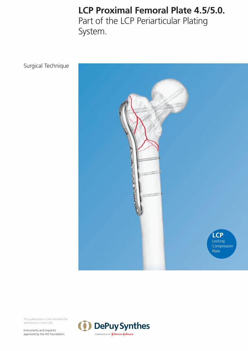
LCP Proximal Femoral Plate 4.5/5.0. Part of the LCP Periarticular Plating System.
Surgical Technique
This publication is not intended for distribution in the USA.
Instruments and implants approved by the AO Foundation.

LCP Proximal Femoral Plate 4.5/5.0 Surgical Technique DePuy Synthes 1
Table of Contents
Image intensifier control
This description alone does not provide sufficient background for direct use of DePuy Synthes products. Instruction by a surgeon experienced in handling these products is highly recommended.
Processing, Reprocessing, Care and MaintenanceFor general guidelines, function control and dismantling of multi-part instruments, as well as processing guidelines for implants, please contact your local sales representative or refer to:http://emea.depuysynthes.com/hcp/reprocessing-care-maintenanceFor general information about reprocessing, care and maintenance of Synthes reusable devices, instrument trays and cases, as well as processing of Synthes non-sterile implants, please consult the Important Information leaflet (SE_023827) or refer to: http://emea.depuysynthes.com/hcp/reprocessing-care-maintenance
Introduction Features and Benefits 2
AO Principles 4
Indications 6
Surgical Technique Implantation 7
Implant Removal 19
General Notes 20
Product Information Plates 21
Screws 22
Drill and Wire Guides 24
Sets 26
MRI Information 28
2 DePuy Synthes LCP Proximal Femoral Plate 4.5/5.0 Surgical Technique
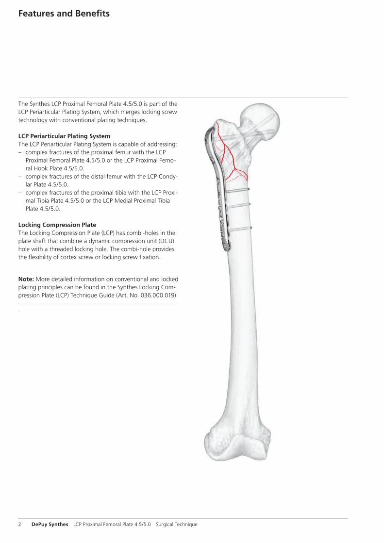
The Synthes LCP Proximal Femoral Plate 4.5/5.0 is part of the LCP Periarticular Plating System, which merges locking screw technology with conventional plating techniques.
LCP Periarticular Plating SystemThe LCP Periarticular Plating System is capable of addressing: – complex fractures of the proximal femur with the LCP
Proximal Femoral Plate 4.5/5.0 or the LCP Proximal Femo-ral Hook Plate 4.5/5.0.
– complex fractures of the distal femur with the LCP Condy-lar Plate 4.5/5.0.
– complex fractures of the proximal tibia with the LCP Proxi-mal Tibia Plate 4.5/5.0 or the LCP Medial Proximal Tibia Plate 4.5/5.0.
Locking Compression PlateThe Locking Compression Plate (LCP) has combi-holes in the plate shaft that combine a dynamic compression unit (DCU) hole with a threaded locking hole. The combi-hole provides the flexibility of cortex screw or locking screw fixation.
Note: More detailed information on conventional and locked plating principles can be found in the Synthes Locking Com-pression Plate (LCP) Technique Guide (Art. No. 036.000.019)
.
Features and Benefits
LCP Proximal Femoral Plate 4.5/5.0 Surgical Technique DePuy Synthes 3
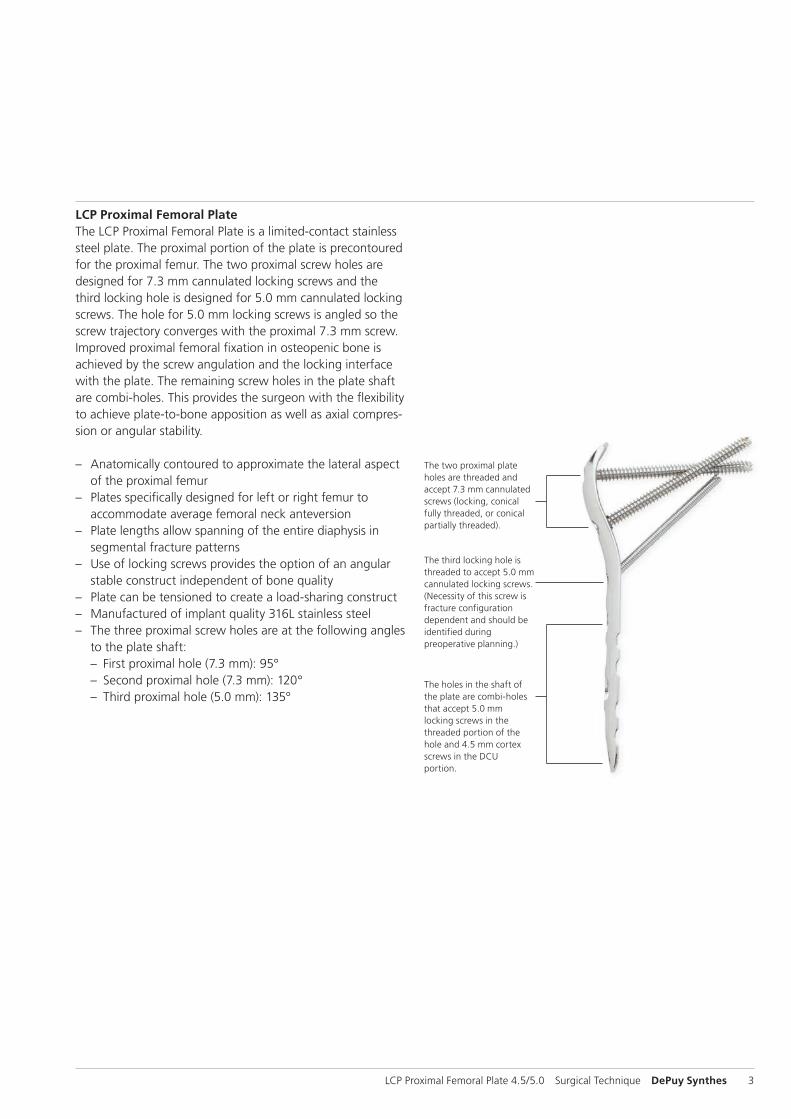
The two proximal plate holes are threaded and accept 7.3 mm cannulated screws (locking, conical fully threaded, or conical partially threaded).
The third locking hole is threaded to accept 5.0 mm cannulated locking screws. (Necessity of this screw is fracture configuration dependent and should be identified during preoperative planning.)
The holes in the shaft of the plate are combi-holes that accept 5.0 mm locking screws in the threaded portion of the hole and 4.5 mm cortex screws in the DCU portion.
LCP Proximal Femoral PlateThe LCP Proximal Femoral Plate is a limited-contact stainless steel plate. The proximal portion of the plate is precontoured for the proximal femur. The two proximal screw holes are designed for 7.3 mm cannulated locking screws and the third locking hole is designed for 5.0 mm cannulated locking screws. The hole for 5.0 mm locking screws is angled so the screw trajectory converges with the proximal 7.3 mm screw. Improved proximal femoral fixation in osteopenic bone is achieved by the screw angulation and the locking interface with the plate. The remaining screw holes in the plate shaft are combi-holes. This provides the surgeon with the flexibility to achieve plate-to-bone apposition as well as axial compres-sion or angular stability.
– Anatomically contoured to approximate the lateral aspect of the proximal femur
– Plates specifically designed for left or right femur to accommodate average femoral neck anteversion
– Plate lengths allow spanning of the entire diaphysis in segmental fracture patterns
– Use of locking screws provides the option of an angular stable construct independent of bone quality
– Plate can be tensioned to create a load-sharing construct – Manufactured of implant quality 316L stainless steel – The three proximal screw holes are at the following angles
to the plate shaft: – First proximal hole (7.3 mm): 95° – Second proximal hole (7.3 mm): 120° – Third proximal hole (5.0 mm): 135°

4 DePuy Synthes LCP Proximal Femoral Plate 4.5/5.0 Surgical Technique
1 M.E. Müller, M. Allgöwer, R. Schneider, and H. Willenegger. AO Manual of Internal Fixation, 3rd Edition. Berlin: Springer-Verlag. 1991.
AO Principles
In 1958, the AO formulated four basic principles1 which have become the guidelines for internal fixation. Those principles as applied to the LCP Proximal Femoral Plate 4.5/5.0 are:
Anatomic reductionAnatomic plate profile assists reduction of metaphysis to diaphysis and facilitates restoration of the neck-shaft angle by proper screw placement.
Stable fixationThe combination of conventional and locking plate fixation offers optimum fixation irrespective of bone density.
Preservation of blood supplyA limited-contact design reduces plate-to-bone contact and helps to preserve the periosteal blood supply.
LCP Proximal Femoral Plate 4.5/5.0 Surgical Technique DePuy Synthes 5
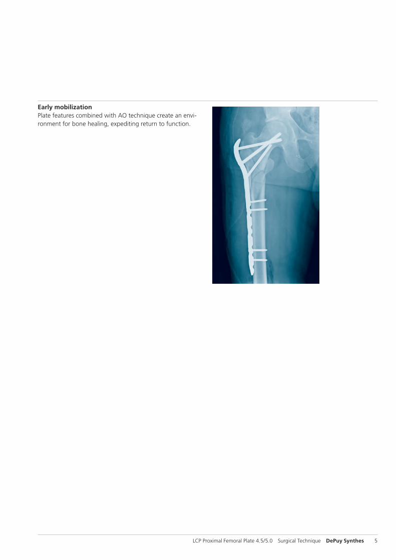
Early mobilizationPlate features combined with AO technique create an envi-ronment for bone healing, expediting return to function.
6 DePuy Synthes LCP Proximal Femoral Plate 4.5/5.0 Surgical Technique
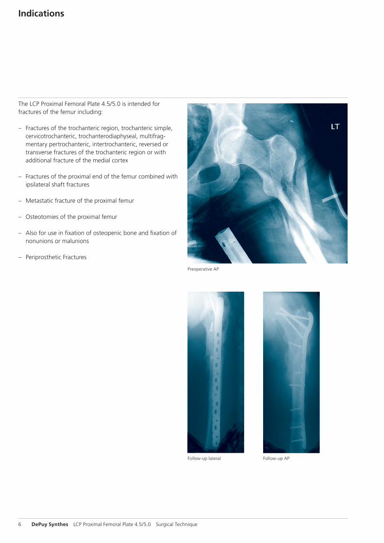
Follow-up lateral Follow-up AP
Preoperative AP
Indications
The LCP Proximal Femoral Plate 4.5/5.0 is intended for fractures of the femur including:
– Fractures of the trochanteric region, trochanteric simple, cervicotrochanteric, trochanterodiaphyseal, multifrag-mentary pertrochanteric, intertrochanteric, reversed or transverse fractures of the trochanteric region or with additional fracture of the medial cortex
– Fractures of the proximal end of the femur combined with ipsilateral shaft fractures
– Metastatic fracture of the proximal femur
– Osteotomies of the proximal femur
– Also for use in fixation of osteopenic bone and fixation of nonunions or malunions
– Periprosthetic Fractures

LCP Proximal Femoral Plate 4.5/5.0 Surgical Technique DePuy Synthes 7
Implantation
1Preparation
Required sets
LCP Proximal Femoral Plate Set 4.5/5.0 (stainless steel)
Periarticular LCP Plating System Instrument Set
Cannulated Locking and Cannulated Conical Screw B 5.0 and 7.3 mm Set
LCP Large Fragment Instrument Set
LCP Large Fragment Screw Set
Complete the preoperative radiographic assessment and pre-pare the preoperative plan. AP and lateral radiographs of the entire femur are necessary for complete evaluation. Traction radiographs and views of the contralateral femur are useful adjuncts in the planning process.
When considering use of the LCP Proximal Femoral Plate, identify proper placement of the three proximal screws.
Use the x-ray templates to aid in planning the procedure. Determine plate length and approximate screw lengths and instruments to be used. Position the patient supine on a radiolucent operating table, or a fracture extension table for lower energy fracture settings. Fluoroscopic visualization of the femur in both AP and lateral views must be verified prior to patient draping.
2Reduce fracture
Reduce the fracture using a fracture table, clamps, Schanz screws, or other conventional reduction techniques. Alterna-tively, provisional indirect fracture reduction may be facili-tated by attaching the LCP Proximal Femoral Plate to the proximal segment with appropriately oriented screws, and then to the diaphysis with plate holding forceps.
X-ray templates for LCP Proximal Femoral Plates 4.5/5.0 (Art. No. 034.000.476 for left femur, Art. No. 034.000.478 for right femur)
8 DePuy Synthes LCP Proximal Femoral Plate 4.5/5.0 Surgical Technique
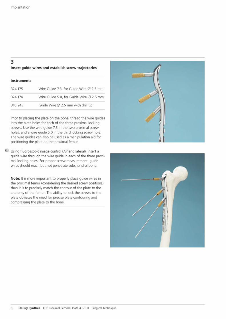
3Insert guide wires and establish screw trajectories
Instruments
324.175 Wire Guide 7.3, for Guide Wire B 2.5 mm
324.174 Wire Guide 5.0, for Guide Wire B 2.5 mm
310.243 Guide Wire B 2.5 mm with drill tip
Prior to placing the plate on the bone, thread the wire guides into the plate holes for each of the three proximal locking screws. Use the wire guide 7.3 in the two proximal screw holes, and a wire guide 5.0 in the third locking screw hole. The wire guides can also be used as a manipulation aid for positioning the plate on the proximal femur.
Using fluoroscopic image control (AP and lateral), insert a guide wire through the wire guide in each of the three proxi-mal locking holes. For proper screw measurement, guide wires should reach but not penetrate subchondral bone.
Note: It is more important to properly place guide wires in the proximal femur (considering the desired screw positions) than it is to precisely match the contour of the plate to the anatomy of the femur. The ability to lock the screws to the plate obviates the need for precise plate contouring and compressing the plate to the bone.
Implantation
A
B
B
95°
50°
LCP Proximal Femoral Plate 4.5/5.0 Surgical Technique DePuy Synthes 9
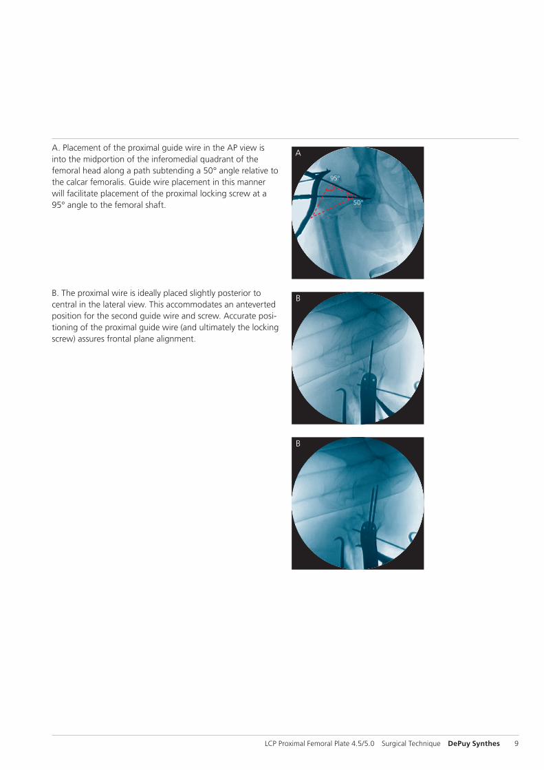
A. Placement of the proximal guide wire in the AP view is into the midportion of the inferomedial quadrant of the femoral head along a path subtending a 50° angle relative to the calcar femoralis. Guide wire placement in this manner will facilitate placement of the proximal locking screw at a 95° angle to the femoral shaft.
B. The proximal wire is ideally placed slightly posterior to central in the lateral view. This accommodates an anteverted position for the second guide wire and screw. Accurate posi-tioning of the proximal guide wire (and ultimately the locking screw) assures frontal plane alignment.
10 DePuy Synthes LCP Proximal Femoral Plate 4.5/5.0 Surgical Technique
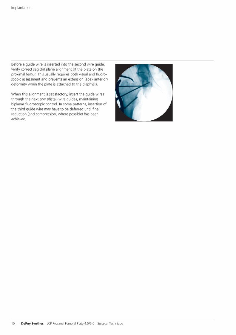
Before a guide wire is inserted into the second wire guide, verify correct sagittal plane alignment of the plate on the proximal femur. This usually requires both visual and fluoro-scopic assessment and prevents an extension (apex anterior) deformity when the plate is attached to the diaphysis.
When this alignment is satisfactory, insert the guide wires through the next two (distal) wire guides, maintaining bi planar fluoroscopic control. In some patterns, insertion of the third guide wire may have to be deferred until final reduction (and compression, where possible) has been achieved.
Implantation
LCP Proximal Femoral Plate 4.5/5.0 Surgical Technique DePuy Synthes 11
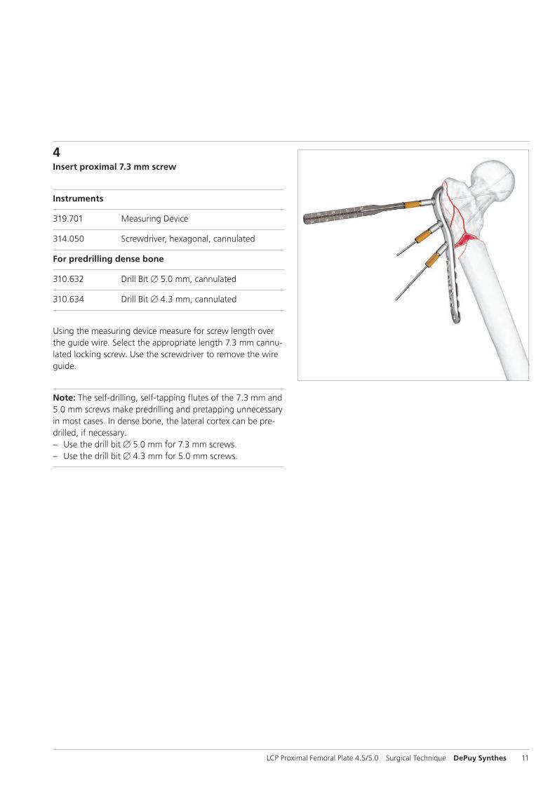
4Insert proximal 7.3 mm screw
Instruments
319.701 Measuring Device
314.050 Screwdriver, hexagonal, cannulated
For predrilling dense bone
310.632 Drill Bit B 5.0 mm, cannulated
310.634 Drill Bit B 4.3 mm, cannulated
Using the measuring device measure for screw length over the guide wire. Select the appropriate length 7.3 mm cannu-lated locking screw. Use the screwdriver to remove the wire guide.
Note: The self-drilling, self-tapping flutes of the 7.3 mm and 5.0 mm screws make predrilling and pretapping unnecessary in most cases. In dense bone, the lateral cortex can be pre-drilled, if necessary. – Use the drill bit B 5.0 mm for 7.3 mm screws. – Use the drill bit B 4.3 mm for 5.0 mm screws.
12 DePuy Synthes LCP Proximal Femoral Plate 4.5/5.0 Surgical Technique
Implantation
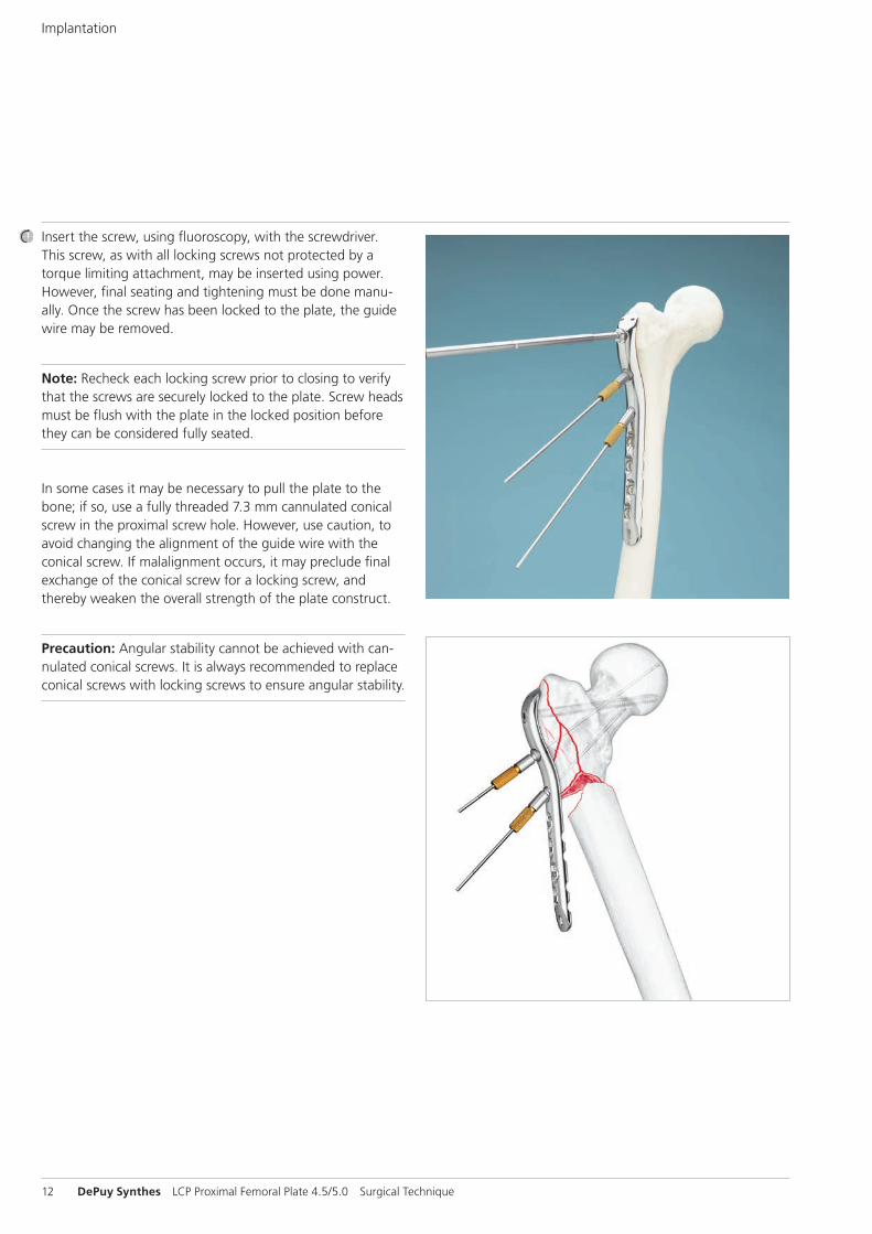
Insert the screw, using fluoroscopy, with the screwdriver. This screw, as with all locking screws not protected by a torque limiting attachment, may be inserted using power. However, final seating and tightening must be done manu-ally. Once the screw has been locked to the plate, the guide wire may be removed.
Note: Recheck each locking screw prior to closing to verify that the screws are securely locked to the plate. Screw heads must be flush with the plate in the locked position before they can be considered fully seated.
In some cases it may be necessary to pull the plate to the bone; if so, use a fully threaded 7.3 mm cannulated conical screw in the proximal screw hole. However, use caution, to avoid changing the alignment of the guide wire with the conical screw. If malalignment occurs, it may preclude final exchange of the conical screw for a locking screw, and thereby weaken the overall strength of the plate construct.
Precaution: Angular stability cannot be achieved with can-nulated conical screws. It is always recommended to replace conical screws with locking screws to ensure angular stability.
LCP Proximal Femoral Plate 4.5/5.0 Surgical Technique DePuy Synthes 13
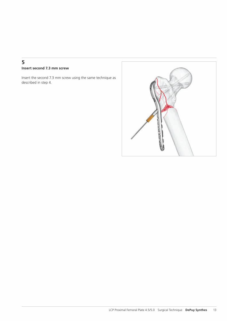
5Insert second 7.3 mm screw
Insert the second 7.3 mm screw using the same technique as described in step 4.
14 DePuy Synthes LCP Proximal Femoral Plate 4.5/5.0 Surgical Technique
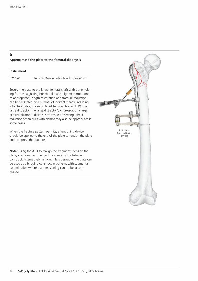
6Approximate the plate to the femoral diaphysis
Instrument
321.120 Tension Device, articulated, span 20 mm
Secure the plate to the lateral femoral shaft with bone hold-ing forceps, adjusting horizontal plane alignment (rotation) as appropriate. Length restoration and fracture reduction can be facilitated by a number of indirect means, including a fracture table, the Articulated Tension Device (ATD), the large distractor, the large distractor/compressor, or a large external fixator. Judicious, soft tissue preserving, direct reduction techniques with clamps may also be appropriate in some cases.
When the fracture pattern permits, a tensioning device should be applied to the end of the plate to tension the plate and compress the fracture.
Note: Using the ATD to realign the fragments, tension the plate, and compress the fracture creates a load-sharing construct. Alternatively, although less desirable, the plate can be used as a bridging construct in patterns with segmental comminution where plate tensioning cannot be accom-plished.
ArticulatedTension Device
321.120
Implantation
LCP Proximal Femoral Plate 4.5/5.0 Surgical Technique DePuy Synthes 15
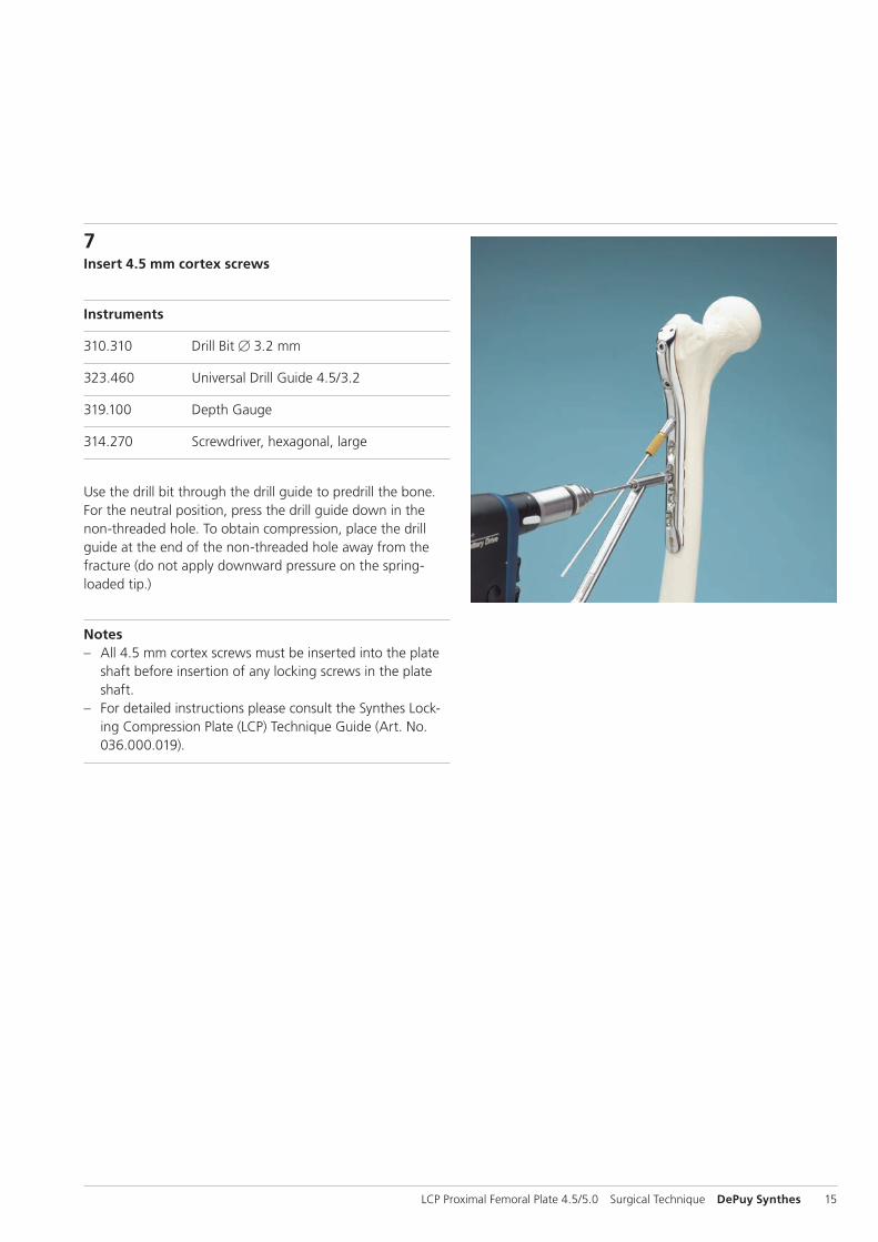
7Insert 4.5 mm cortex screws
Instruments
310.310 Drill Bit B 3.2 mm
323.460 Universal Drill Guide 4.5/3.2
319.100 Depth Gauge
314.270 Screwdriver, hexagonal, large
Use the drill bit through the drill guide to predrill the bone. For the neutral position, press the drill guide down in the non-threaded hole. To obtain compression, place the drill guide at the end of the non-threaded hole away from the fracture (do not apply downward pressure on the spring-loaded tip.)
Notes – All 4.5 mm cortex screws must be inserted into the plate
shaft before insertion of any locking screws in the plate shaft.
– For detailed instructions please consult the Synthes Lock-ing Compression Plate (LCP) Technique Guide (Art. No. 036.000.019).
16 DePuy Synthes LCP Proximal Femoral Plate 4.5/5.0 Surgical Technique
Implantation
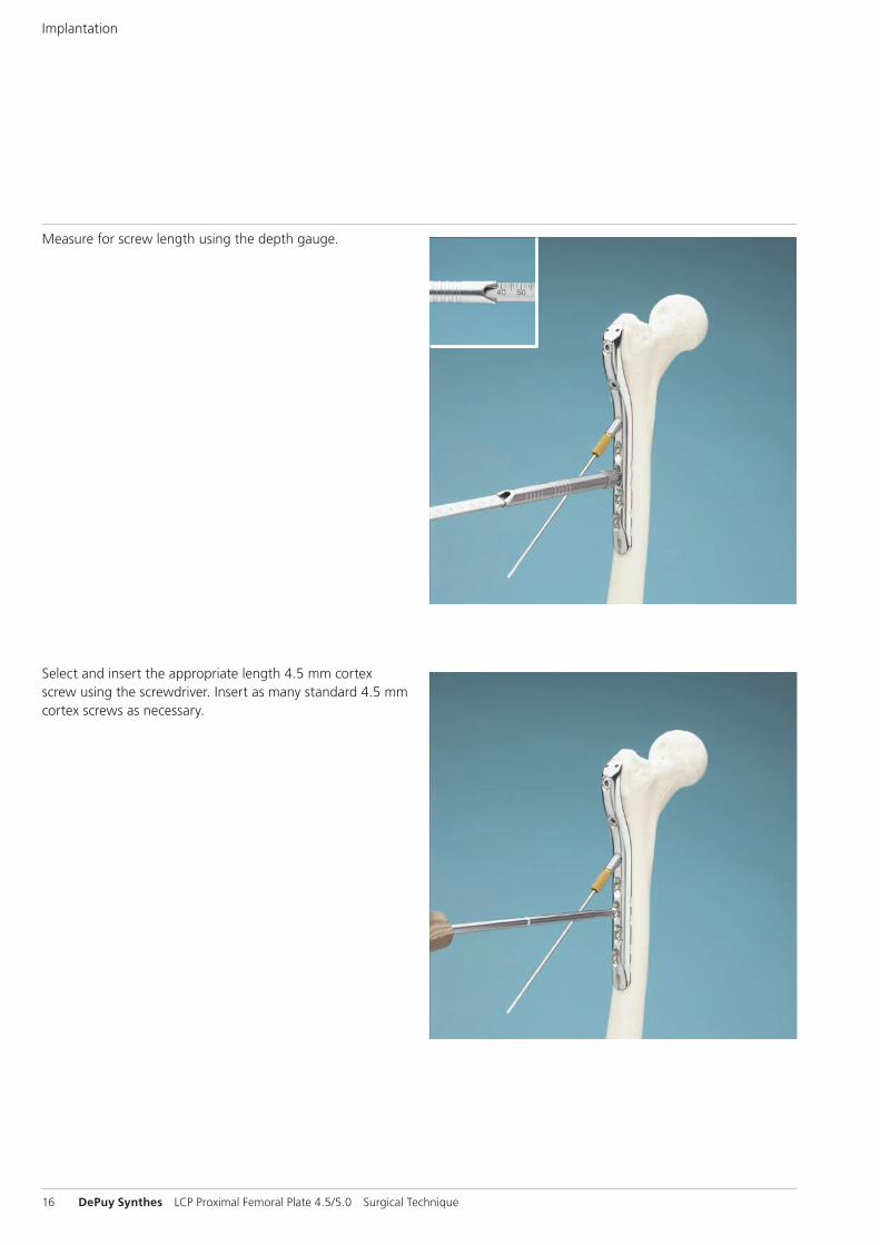
Select and insert the appropriate length 4.5 mm cortex screw using the screwdriver. Insert as many standard 4.5 mm cortex screws as necessary.
Measure for screw length using the depth gauge.
LCP Proximal Femoral Plate 4.5/5.0 Surgical Technique DePuy Synthes 17
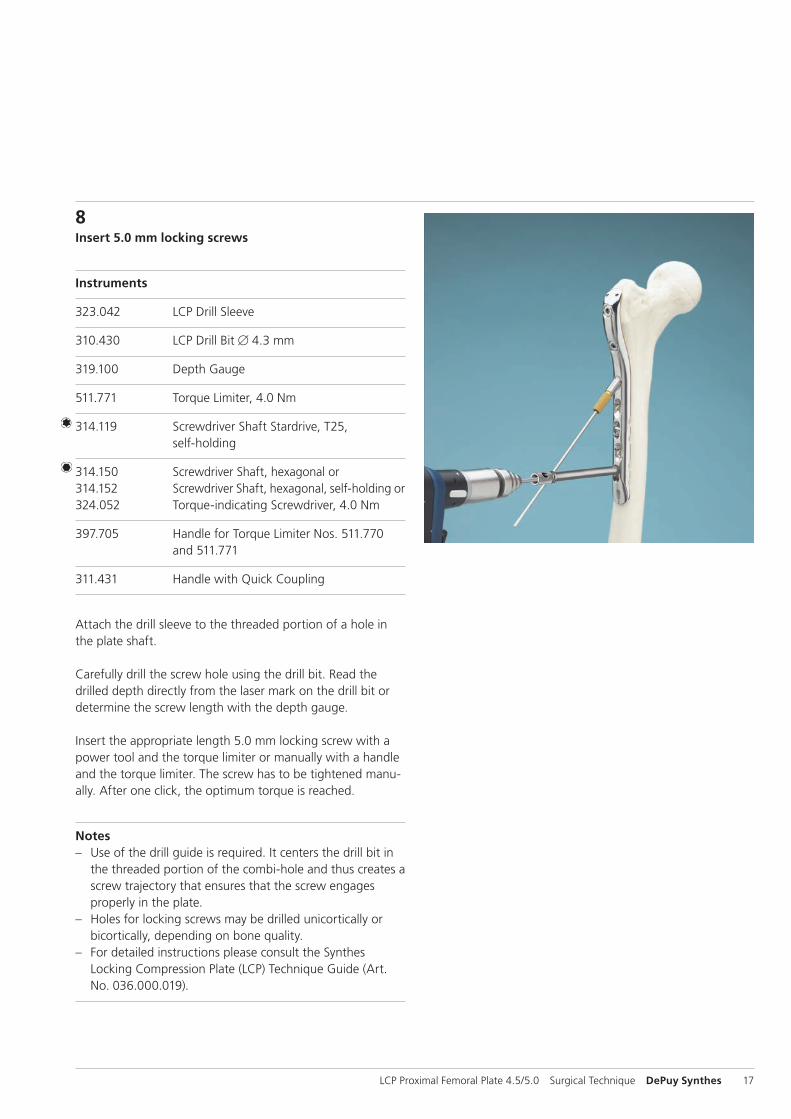
8Insert 5.0 mm locking screws
Instruments
323.042 LCP Drill Sleeve
310.430 LCP Drill Bit B 4.3 mm
319.100 Depth Gauge
511.771 Torque Limiter, 4.0 Nm
314.119 Screwdriver Shaft Stardrive, T25, self-holding
314.150 Screwdriver Shaft, hexagonal or314.152 Screwdriver Shaft, hexagonal, self-holding or324.052 Torque-indicating Screwdriver, 4.0 Nm
397.705 Handle for Torque Limiter Nos. 511.770 and 511.771
311.431 Handle with Quick Coupling
Attach the drill sleeve to the threaded portion of a hole in the plate shaft.
Carefully drill the screw hole using the drill bit. Read the drilled depth directly from the laser mark on the drill bit or determine the screw length with the depth gauge.
Insert the appropriate length 5.0 mm locking screw with a power tool and the torque limiter or manually with a handle and the torque limiter. The screw has to be tightened manu-ally. After one click, the optimum torque is reached.
Notes – Use of the drill guide is required. It centers the drill bit in
the threaded portion of the combi-hole and thus creates a screw trajectory that ensures that the screw engages properly in the plate.
– Holes for locking screws may be drilled unicortically or bicortically, depending on bone quality.
– For detailed instructions please consult the Synthes Locking Compression Plate (LCP) Technique Guide (Art. No. 036.000.019).
18 DePuy Synthes LCP Proximal Femoral Plate 4.5/5.0 Surgical Technique
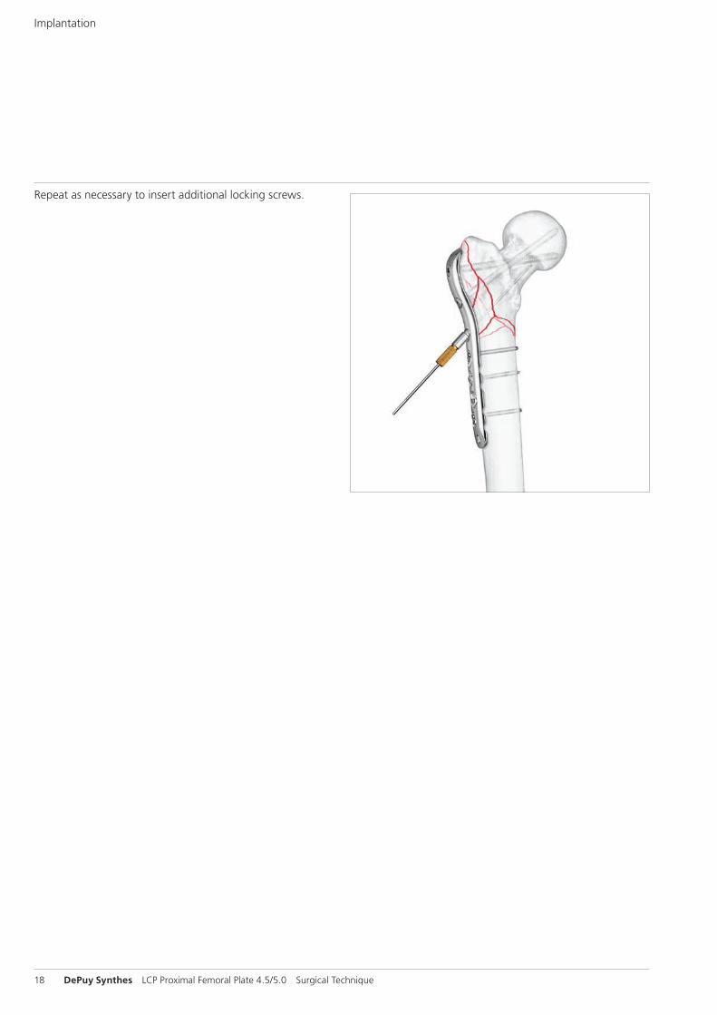
Repeat as necessary to insert additional locking screws.
Implantation

LCP Proximal Femoral Plate 4.5/5.0 Surgical Technique DePuy Synthes 19
9Insert oblique 5.0 mm cannulated locking screw
Instruments
319.701 Measuring Device
314.050 Screwdriver, hexagonal, cannulated
Using the wire guide and guide wire previously inserted at this hole location, measure for the screw length with the measuring device. The correct length measurement will place the screw at the tip of the guide wire.
Screw length considerations: The angled 5.0 mm cannulated locking screw in the plate shaft is intended to converge with the 95°, 7.3 mm screw to create a buttress which will pro-vide additional stability. This convergence should occur when using a 5.0 mm cannulated locking screw that is 85 mm in length.
Remove the wire guide and insert the appropriate length screw over the guide wire and into the bone using the screwdriver. Locking screws may be inserted using power equipment. However, final seating and tightening must be done manually.
Precautions – The need for this screw is fracture configuration depen-
dent and should be determined during preoperative planning.
– Securely tighten all locking screws again prior to closing.
10Implant RemovalIn case the physician decides to remove the implants, im-plants can be removed by using general surgical instruments. In case of difficult removal circumstances, a Screw Extraction Set is available with corresponding instructions (036.000.917).
20 DePuy Synthes LCP Proximal Femoral Plate 4.5/5.0 Surgical Technique
Cleaning
Instruments
319.461 Cleaning Stylet B 2.5 mm, for Cannulated Instruments
Cleaning the cannulation in each instrument is imperative for proper function. Instruments should be cleared intraopera-tively using the cleaning stylet to prevent accumulation of debris in the cannulation and potential binding of the instru-ments about the guide wire.
Preliminary plate shaft attachmentThe Tension Device B 4.0 mm (324.033) can be used to ap-proximate the plate shaft to the diaphysis and counteract medial diaphyseal displacement.
Reduction and fixation – If an extension table is used, careful traction should be
applied to prevent the gastrocnemius muscle from pulling the distal fragment posteriorly or into hyperflexion. Poste-rior support of the distal fragment can assist reduction.
– Sagittal plane reduction may be facilitated using a Schanz screw as a “joystick” in the anterior cortex of the distal fragment. Insertion of a Schanz screw into the proximal fragment may also be helpful. Should it still be impossible to achieve fracture reduction, extend the incision to im-prove access.
– When using a radiolucent table, towel bumps can be used under the diaphyseal segment to help reduce the fracture in the lateral plane.
– Limb axis can be checked using the C-Arm and a cautery cord from the femoral head to the center of the ankle joint on an AP view. Use the C-Arm at the knee to check that the cord passes 10 mm medially to the center of the knee joint. Adjustment to varus-valgus reduction should be performed before locking screw placement in the malaligned fragment.
– Fractures not treated acutely should be placed in skeletal traction to maintain length until plate fixation can be performed.
General Notes
LCP Proximal Femoral Plate 4.5/5.0 Surgical Technique DePuy Synthes 21
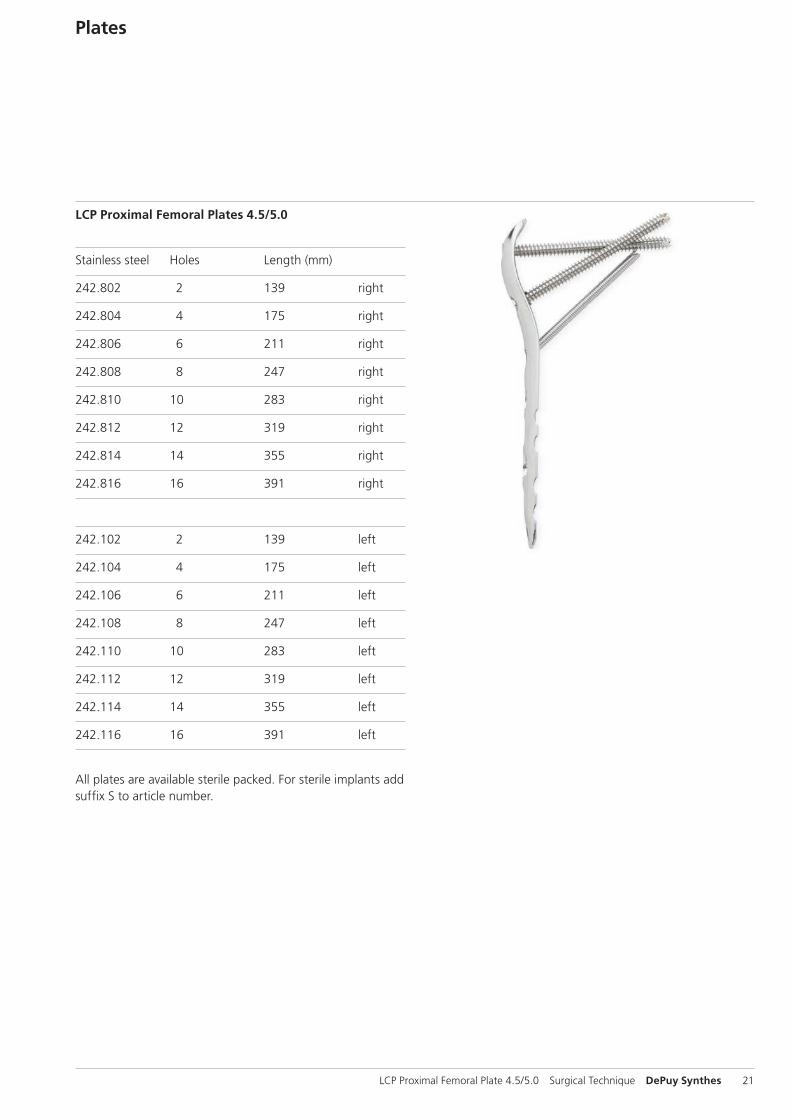
Plates
LCP Proximal Femoral Plates 4.5/5.0
Stainless steel Holes Length (mm)
242.802 2 139 right
242.804 4 175 right
242.806 6 211 right
242.808 8 247 right
242.810 10 283 right
242.812 12 319 right
242.814 14 355 right
242.816 16 391 right
242.102 2 139 left
242.104 4 175 left
242.106 6 211 left
242.108 8 247 left
242.110 10 283 left
242.112 12 319 left
242.114 14 355 left
242.116 16 391 left
All plates are available sterile packed. For sterile implants add suffix S to article number.

22 DePuy Synthes LCP Proximal Femoral Plate 4.5/5.0 Surgical Technique
Cannulated Conical Screw B 7.3 mm (02.207.250–02.207.295) Compresses the plate to the bone – Smooth conical head – Fully threaded shaft – Self-drilling, self-tapping tip
Cannulated Locking Screw B 7.3 mm (02.207.020–02.207.145)Creates a locked, fixed-angle screw-plate construct – Threaded conical head – Fully threaded shaft – Self-drilling, self-tapping tip
Cannulated Conical Screw B 7.3 mm (02.207.450–02.207.545) Compresses the plate to the bone and provides interfragmentary compression – Smooth conical head – Partially threaded shaft – Self-drilling, self-tapping tip
Cannulated Locking Screw B 5.0 mm (02.205.025–02.205.145) Creates a locked, fixed-angle screw-plate construct – Threaded conical head – Fully threaded shaft – Self-drilling, self-tapping tip
Screws
LCP Proximal Femoral Plate 4.5/5.0 Surgical Technique DePuy Synthes 23
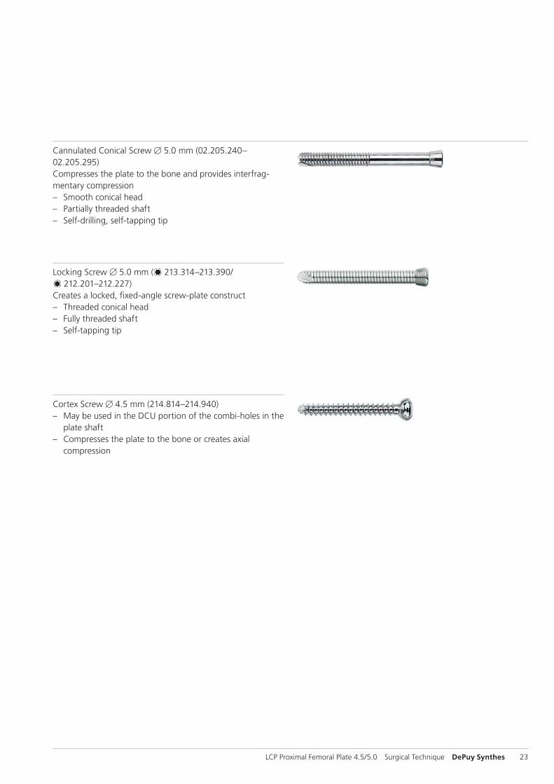
Locking Screw B 5.0 mm ( 213.314–213.390/ 212.201–212.227)
Creates a locked, fixed-angle screw-plate construct – Threaded conical head – Fully threaded shaft – Self-tapping tip
Cannulated Conical Screw B 5.0 mm (02.205.240–02.205.295) Compresses the plate to the bone and provides interfrag-mentary compression – Smooth conical head – Partially threaded shaft – Self-drilling, self-tapping tip
Cortex Screw B 4.5 mm (214.814–214.940) – May be used in the DCU portion of the combi-holes in the
plate shaft – Compresses the plate to the bone or creates axial
compression
24 DePuy Synthes LCP Proximal Femoral Plate 4.5/5.0 Surgical Technique
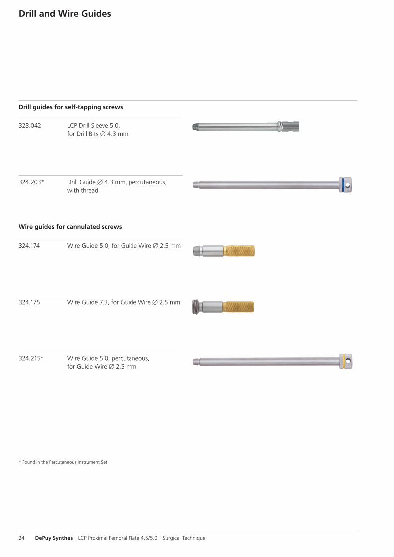
* Found in the Percutaneous Instrument Set
Drill and Wire Guides
324.203* Drill Guide B 4.3 mm, percutaneous, with thread
323.042 LCP Drill Sleeve 5.0, for Drill Bits B 4.3 mm
Drill guides for self-tapping screws
324.174 Wire Guide 5.0, for Guide Wire B 2.5 mm
324.175 Wire Guide 7.3, for Guide Wire B 2.5 mm
324.215* Wire Guide 5.0, percutaneous, for Guide Wire B 2.5 mm
Wire guides for cannulated screws
LCP Proximal Femoral Plate 4.5/5.0 Surgical Technique DePuy Synthes 25
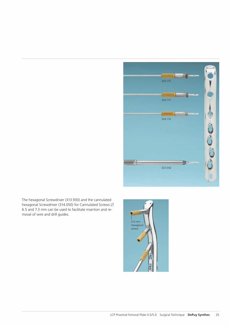
4.0 mm hexagonal recess
The hexagonal Screwdriver (313.930) and the cannulated hexagonal Screwdriver (314.050) for Cannulated Screws B 6.5 and 7.3 mm can be used to facilitate insertion and re-moval of wire and drill guides.
323.042
324.175
324.175
324.174
26 DePuy Synthes LCP Proximal Femoral Plate 4.5/5.0 Surgical Technique
Sets
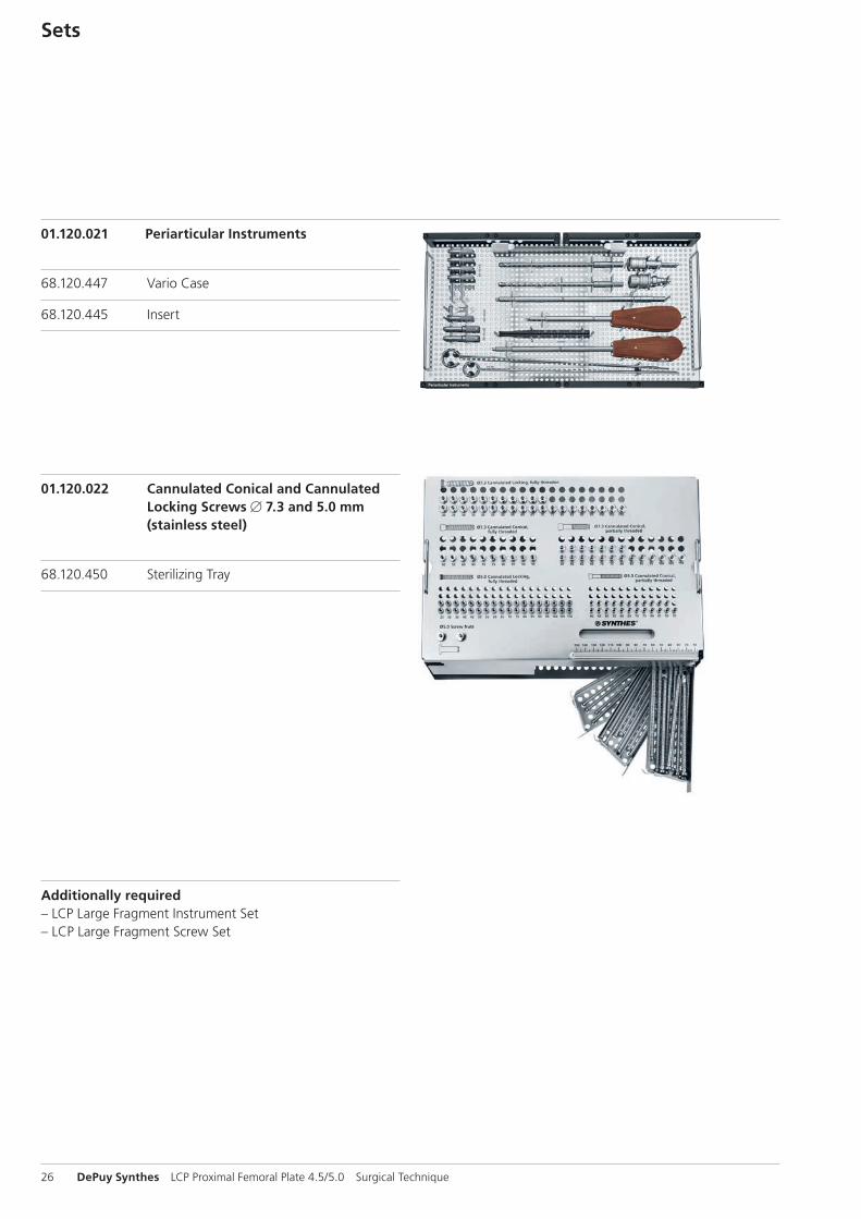
01.120.021 Periarticular Instruments
68.120.447 Vario Case
68.120.445 Insert
01.120.022 Cannulated Conical and Cannulated Locking Screws B 7.3 and 5.0 mm (stainless steel)
68.120.450 Sterilizing Tray
Additionally required– LCP Large Fragment Instrument Set– LCP Large Fragment Screw Set
LCP Proximal Femoral Plate 4.5/5.0 Surgical Technique DePuy Synthes 27
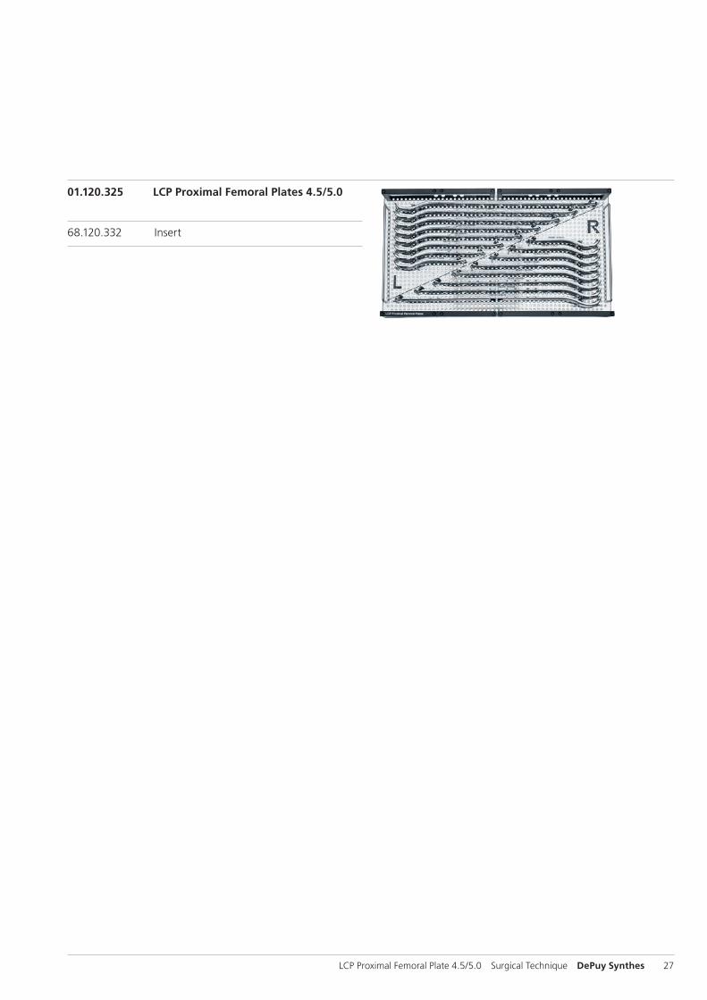
01.120.325 LCP Proximal Femoral Plates 4.5/5.0
68.120.332 Insert
28 DePuy Synthes LCP Proximal Femoral Plate 4.5/5.0 Surgical Technique
MRI Information
Torque, Displacement and Image Artifacts according to ASTM F 2213-06, ASTM F 2052-06e1 and ASTM F2119-07Non-clinical testing of worst case scenario in a 3 T MRI system did not reveal any relevant torque or displacement of the construct for an experimentally measured local spatial gradient of the magnetic field of 3.69 T/m. The largest image artifact extended approximately 169 mm from the construct when scanned using the Gradient Echo (GE). Testing was conducted on a 3 T MRI system.
Radio-Frequency-(RF-)induced heating according to ASTM F2182-11aNon-clinical electromagnetic and thermal testing of worst case scenario lead to peak temperature rise of 9.5 °C with an average temperature rise of 6.6 °C (1.5 T) and a peak temperature rise of 5.9 °C (3 T) under MRI Conditions using RF Coils [whole body averaged specific absorption rate (SAR) of 2 W/kg for 6 minutes (1.5 T) and for 15 minutes (3 T)].
Precautions: The above mentioned test relies on non-clini-cal testing. The actual temperature rise in the patient will depend on a variety of factors beyond the SAR and time of RF application. Thus, it is recommended to pay particular attention to the following points: – It is recommended to thoroughly monitor patients under-
going MR scanning for perceived temperature and/or pain sensations.
– Patients with impaired thermo regulation or temperature sensation should be excluded from MR scanning proce-dures.
– Generally it is recommended to use a MR system with low field strength in the presence of conductive implants. The employed specific absorption rate (SAR) should be reduced as far as possible.
– Using the ventilation system may further contribute to reduce temperature increase in the body.


0123
Synthes GmbHEimattstrasse 34436 OberdorfSwitzerlandTel: +41 61 965 61 11Fax: +41 61 965 66 00www.depuysynthes.com
This publication is not intended for distribution in the USA.
All surgical techniques are available as PDF files at www.depuysynthes.com/ifu ©
DeP
uy S
ynth
es T
raum
a, a
div
isio
n of
Syn
thes
Gm
bH. 2
015.
A
ll rig
hts
rese
rved
. 03
6.0
00.
403
D
SEM
/TR
M/0
714/
0121
(2)
11/1
5