Embed Size (px)
Citation preview

LCP Superior Anterior Clavicle Plate.The anatomically precontoured fixationsystem with angular stability for clavicleshaft and lateral clavicle.
Technique Guide


Synthes 1
Table of Contents
Introduction
Surgical Technique
Product Information
Synthes Biomaterials Overview 32
LCP Superior Anterior Clavicle Plate 2
AO Principles 4
Indications 5
Preparation 6
Implantation: Open Approach 8
Implantation: Minimally Invasive Approach 12
Screw Insertion 16
Implant Removal 24
Plates 25
Screws 27
Instruments 28
Sets 30
Image intensifier control
WarningThis description alone does not provide sufficient background for direct use ofthe instrument set. Instruction by a surgeon experienced in handling theseinstruments is highly recommended.
Reprocessing, Care and Maintenance of Synthes InstrumentsFor general guidelines, function control and dismantling of multi-part instruments,please refer to: www.synthes.com/reprocessing

2 Synthes LCP Superior Anterior Clavicle Plate Technique Guide
LCP Superior Anterior Clavicle Platewith lateral extension – Fractures of the lateral clavicle– Malunions of the lateral clavicle– Non-unions of the lateral clavicle– Available in longer versions for
lateral fractures with associated shaft fractures
LCP Superior Anterior Clavicle Platewithout lateral extension – Fractures of the clavicle shaft– Malunions of the clavicle shaft– Non-unions of the clavicle shaft
LCP Superior Anterior Clavicle Plate.The anatomically precontoured fixationsystem with angular stability for lateralclavicle and clavicle shaft.
Indications
Also available: LCP Clavicle Hook Plate – Acromioclavicular joint dislocation– Fractures of the lateral clavicle
Lateral holes2.7 mm locking or 2.4 mm cortex screws
Shaft holes3.5 mm locking or 3.5 mmcortex screws
Small diverging screws inlateral end ensure good screwpurchase and increased pull outstrength
Undercuts reduceimpairment of bloodsupply
Recon plate segmentsallow any necessary platecontouring
Offset screws minimize the risk of bonesplitting
A rounded profile, and screw heads that are seated flush in the plate, prevent conflicts between the plate and surrounding soft tissue

0 %
100 %
200 %
LCP Locking Compression Plate Angular stable fixation of fragmentsregardless of bone quality
Minimised risk of primary and second-ary loss of reduction, even underhigh dynamic loading
Reduced impairment of periostealblood supply due to the limited platecontact
Good purchase also in osteoporoticbone and in multifragment factures
Tapered plate tipfacilitates percutaneous insertion and prevents softtissue irritation
LCP combi-holeIntraoperative choice between compres-sion and angular stable locking
With standard screws:interfragmental or dynamic-axialcompression
With locking screws: stable plate-screw connection withoutloss of reduction, regardless of platemodelling
Positioning inscriptionsLateral arrow and sign forleft or right
LCP Superior Anterior Clavicle PlateRecon Plate
Strength under compression load
Anatomically pre-shaped, twisted design
Lateral superior placement– Less need to detach muscles
than with anterior placement– Easier plate placement
Medial anterior placement– Reduces risk of damaging surround-
ing structures– Less plate prominence– Easier drilling and screw insertion
under the chin
Synthes 3

4 Synthes LCP Superior Anterior Clavicle Plate Technique Guide
AO Principles
In 1958, the AO formulated four basic principles, which have become the guidelines for internal fixation.1 Those principles as applied to the LCP Superior Anterior ClaviclePlate are:
Anatomic reductionPrecontoured plate assists in reduction of metaphysis to diaphysis and facilitates restoration of articular surface.
Stable fixationLocking screws create a fixed-angle construct providing angular stability.
Preservation of blood supplyTapered end for submuscular plate insertion preserves tissue viability.
Early, active mobilizationEarly mobilization per standard AO technique creates an environment for bone healing, expediting a return to optimal function.
1 Müller ME, Allgöwer M, Schneider R, Willenegger H (1995) Manual of InternalFixation. 3rd, expanded and completely revised ed. 1991. Berlin, Heidelberg, New York: Springer

Synthes 5
Indications
– Fractures of the clavicle shaft– Fractures of the lateral clavicle– Malunions of the clavicle– Non-unions of the clavicle

6 Synthes LCP Superior Anterior Clavicle Plate Technique Guide
Preparation
1Preoperative planning
Complete the preoperative radiographic assessment andprepare the preoperative plan. Use the x-ray templates forLCP Superior Anterior Clavicle Plate (Art. No. 034.000.540for right and left clavicles) to determine the length of theplate and the position of the screws.

Synthes 7
2Postition and prepare patient
Position the patient in a supine position on a radiolucentoperating table. Provide enough room to swing the image intensifier 45° in both directions to view the clavicle in two planes intra-operatively.
Notes – Longer tubes for anesthesia may be required.– Prepare the associated arm so that it can be intra-operati-
vely mobilized. The mobilization of the arm can be used as reduction aid.
8 Synthes LCP Superior Anterior Clavicle Plate Technique Guide
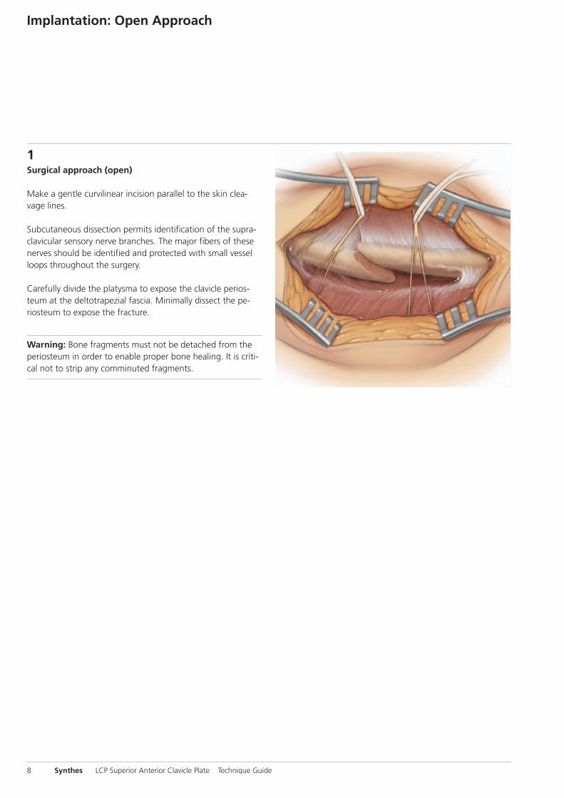
1Surgical approach (open)
Make a gentle curvilinear incision parallel to the skin clea-vage lines.
Subcutaneous dissection permits identification of the supra-clavicular sensory nerve branches. The major fibers of thesenerves should be identified and protected with small vesselloops throughout the surgery.
Carefully divide the platysma to expose the clavicle perios-teum at the deltotrapezial fascia. Minimally dissect the pe-riosteum to expose the fracture.
Warning: Bone fragments must not be detached from theperiosteum in order to enable proper bone healing. It is criti-cal not to strip any comminuted fragments.
Implantation: Open Approach

Synthes 9
2Fracture reduction and temporary fixation
Normal length, axis angulation and rotation should be restored.
After exposing the fracture, the two main fragments are dis-tracted and the length of the clavicle is restored. If the boneends are angled or oblique, reduce with a pointed or serratedreduction forceps.
Any large comminuted fragments should also be reducedand held temporarily with small pointed bone clamps or K-wires. Assess and plan for any temporary fixation so as tonot interfere with the placement of the definitive fixation implants.
K-wires can be placed through the distal end of the plate to assist with temporary maintenance of the reduction andfor plate placement.
Additional options for maintaining the reduction include independent lag screws and lag screws inserted through the plate.
Warning: Bone fragments must not be detached from the periosteum in order to enable proper bone healing. It is critical not to strip any comminuted fragments
Option: The LCP Superior Anterior Clavicle Plate can be used for biological, bridging osteosynthesis. Only the mainfragments are reduced and the actual fracture zone is notengaged with any screw.

3Determine plate length and adapt plate
Optional instruments
329.040/ Bending Iron for Plates 2.4 to 3.5,329.050 length 145 mm
329.291 Bending Pliers for Clavicle Plates, length 227 mm
329.300 Bending Press, length 400 mm
Select a plate length appropriate for the fracture.
Due to varying patient anatomy, plate bending may be ne-cessary. Using the bending irons, bending pliers and/or theplate press, contour the plate as needed. For an optimum fit,the plate can be bent at each notch in the plane of the shaft.
Warning: Avoid bending the plate back and forth, as thiscan weaken the plate.
Tip: To avoid damage to the LCP threads from extensivebending, insert a LCP drill sleeve into the threaded hole forprotection.
Note: This locking plate is precontoured to fit the clavicle. If the plate contour is changed, it is important to check theposition of the screws under image intensification.
Implantation: Open Approach
10 Synthes LCP Superior Anterior Clavicle Plate Technique Guide

Synthes 11
4Position plate and attach temporarily
Position the plate on the reduced bone, and attach it tem-porarily with a 3.5 mm cortex screw or plate holding forceps.
After plate insertion, check alignment on the bone using animage intensifier.

12 Synthes LCP Superior Anterior Clavicle Plate Technique Guide
Implantation: Minimally Invasive Approach
1Surgical approach (minimally invasive)
The operation is performed from medial towards lateral tominimize the risk of harming central vessels.
Make a 2 cm incision parallel to the skin cleavage lines overthe medial end of the clavicle.
Tip: To reduce the chance of post-operative interference be-tween the wound and the plate, use a finger to push theskin cranially over the clavicle and cut the skin on the claviclebone. When removing the finger, the skin will glide back andthe cut will be positioned below the clavicle.
The subcutis is carefully spread and dissected to the cortex ofthe medial clavicle. Ensure that soft tissue is removed fromthe anterior medial and the superior lateral parts of the boneto enable plate placement.

Synthes 13
2Reduce fracture
Normal length, axis angulation and rotation should be re-stored. In some cases, this can be controlled percutaneouslywith one’s fingers or with pointed forceps.
Otherwise, an additional 3 cm incision across the fractureand along the cleavage lines is done. Reduction is accom-plished through distraction and rotation, if required.
Warning: Bone fragments must not be detached from theperiosteum in order to enable proper bone healing. It is criti-cal not to strip any comminuted fragments.
Option: The LCP Superior Anterior Clavicle Plate can be usedfor biological, bridging osteosynthesis. Only the main frag-ments are reduced while the actual fracture zone is not en-gaged with any screws.

Implantation: Minimally Invasive Approach
3Determine plate length and adapt plate
Optional instruments
329.040/ Bending Iron for Plates 2.4 to 3.5,329.050 length 145 mm
329.291 Bending Pliers for Clavicle Plates, length 227 mm
329.300 Bending Press, length 400 mm
Select a plate length appropriate for the fracture. The opti-mal plate length can be determined by x-ray or by placing iton the skin and palpating.
Due to varying patient anatomy, plate bending may be ne-cessary. Using the bending irons, bending pliers and/or theplate press, contour the plate as needed. For an optimum fit,the plate can be bent at each notch in the plane of the shaft.
Warning: Avoid bending the plate back and forth, as thiscan weaken the plate.
Tip: To avoid damage to the LCP threads from extensivebending, insert a LCP drill sleeve into the threaded hole forprotection.
Note: This locking plate is precontoured to fit the clavicle. If the plate contour is changed, it is important to check the position of the screws under image intensification.
14 Synthes LCP Superior Anterior Clavicle Plate Technique Guide

Synthes 15
4Insert and position plate
Instrument
323.027 LCP Drill Sleeve 3.5, for Drill Bits � 2.8 mm
LCP drill sleeves are fixed in the medial part of the plate andused as insertion handles. The plate can be palpated andguided percutaneously from the medial to the lateral frag-ment.
Position the plate on the reduced bone, and pull the bone tothe plate by inserting a 3.5 mm cortex screw in both mainfragments (see chapter “Insert Screw” section 2a).
After plate insertion, check alignment on the bone using animage intensifier.

16 Synthes LCP Superior Anterior Clavicle Plate Technique Guide
Screw Insertion
Determine the combination of screws to be used for fixation.If a combination of locking and cortex screws will be used,cortex screws should be inserted first to pull the bone to theplate.
Note: If the LCP Superior Anterior Clavicle Plate is used forbridging osteosynthesis, a minimum of two locking screwsshould be used in both main fragments. The actual fracturezone is generally not engaged with any screws.
1Verify screw placement
Since the direction of the locking screws depends on thecontour of the plate, final screw position may be verified under image intensification with K-wires before insertion.This becomes especially important when the plate has beenmanually contoured, applied near a joint, or for non-stan-dard anatomy.
Optional: Observe the direction of the drill bit while drillingunder image intensification.

Synthes 17
2Screw Fixation
2aFixation with � 3.5 mm cortex screws
Instruments
310.250 Drill Bit � 2.5 mm, length 110/85 mm, for Quick Coupling
323.360 Universal Drill Guide 3.5
319.010 Depth Gauge for Screws � 2.7 to 4.0 mm,measuring range up to 60 mm
314.030 Screwdriver Shaft, hexagonal, small, � 2.5 mm
311.431 Handle with Quick Coupling
Use the 2.5 mm drill bit with the 3.5 universal drill guide topre-drill the bone through both cortices.

For neutral position For compression
3
1 2
Screw Insertion
Warning: Avoid contact with the subclavian artery andbrachial plexus when drilling through the clavicle.
To set screws in a neutral position, press the drill guide downin the non-threaded hole (1). To obtain compression, placethe drill guide at the end of the non-threaded hole awayfrom the fracture, being sure not to apply downward pres-sure on the spring loaded tip (2).
Determine the required length of the cortex screw using thedepth gauge (3).
18 Synthes LCP Superior Anterior Clavicle Plate Technique Guide

Synthes 19
4Insert the appropriate 3.5 mm cortex screw using the hexagonal screwdriver or the hexagonal shaft (4).

2
12bFixation with � 3.5 mm locking screws
Note: If a locking screw will be used as the first screw, besure that the fracture is reduced and the plate is held securely to the bone. This prevents plate rotation as thescrew is locked to the plate.
Instruments
323.027 LCP Drill Sleeve 3.5, for Drill Bits � 2.8 mm
310.284 LCP Drill Bit � 2.8 mm, length 165 mm
319.010 Depth Gauge for Screws � 2.7 to 4.0 mm,measuring range up to 60 mm
314.030 Screwdriver Shaft, hexagonal, small, � 2.5 mm
or314.116 Screwdriver Shaft Stardrive 3.5 T15
511.770/773 Torque Limiter, 1.5 Nm
397.705/ Handle for Torque Limiter /Handle with311.431 Quick Coupling
Insert the drill sleeve into a 3.5 mm locking hole until fullyseated. Drill through both cortices with the drill bit (1).
Warning: Avoid contact with the subclavian artery andbrachial plexus when drilling through the clavicle.
Remove the drill guide. Use the depth gauge to determinethe screw length (2).
Screw Insertion
20 Synthes LCP Superior Anterior Clavicle Plate Technique Guide

Synthes 21
3Insert the locking screw with the appropriate screwdrivershaft (hexagonal or Stardrive recess) mounted on the 1.5 Nmtorque limiter. Insert the screw manually or by power until aclick is heard. If a power tool is used, reduce speed whentightening the head of the locking screw into the plate (3).
Repeat the above steps for all required shaft holes.

1
2
2cFixation with � 2.7 mm locking screws (only in plateswith lateral extension)
Instruments
323.061 LCP Drill Sleeve 2.7 (head LCP 2.4), with Scale up to 60 mm, for Drill Bits � 2.0 mm
323.062 Drill Bit � 2.0 mm, with double marking,length 140/115 mm, 3-flute, for QuickCoupling
313.304 Screwdriver Shaft Stardrive, T8, cylindrical,with groove
511.776 Torque Limiter, 0.8 Nm, with AO/ASIF Quick Coupling
311.430 Handle with Quick Coupling
Optional instruments
319.005 Depth Gauge for Screws � 2.0 and 2.4 mm, measuring range up to 40 mm
319.010 Depth Gauge for Screws � 2.7 to 4.0 mm,measuring range up to 60 mm
313.301 Holding Sleeve for LCP Screw Stardrive � 2.4/2.7 mm
313.300 Combined Holding Sleeve for CortexScrews Stardrive 2.4/2.7 mm
Insert the drill sleeve into a 2.7 mm locking hole until fullyseated. Use the drill bit to drill to the desired depth (1).
Warning: Avoid contact with the subclavian artery andbrachial plexus when drilling through the clavicle.
Determine the required length of the screw by using thescale on the drill guide and the drill sleeve. If a single mark-ing is visible on the drill bit, the scale from 0–30 mm applies;if a double marking is visible, the scale from 30–60 mm applies (2).
Screw Insertion
22 Synthes LCP Superior Anterior Clavicle Plate Technique Guide

Synthes 23
3
4
If the depth gauge 319.010 is used for 2.7 mm screws, sub-tract 4 mm from the indicated length to obtain the correctscrew length.
Note: The above mentioned methods result in screws that end flush with the opposite cortex. Should bicortical screws be required, insert screws that are 1–2 mm longerthan measured. Screws near a joint should be shorter than measured.
The 2.7 mm locking screw can be inserted manually or withpower. For manual insertion, use a handle with quick cou-pling. Use the StarDrive screwdriver shaft holding sleeve ifnecessary (3).
For powered insertion of the 2.7 mm locking screws, use the screwdriver shaft attached to the 0.8 Nm torque limitingattachment.
Important: always use a TLA when inserting LCP lockingscrews to avoid plate, screw and/or screwdriver damage.
Option: Use 2.4 mm cortex screws.
Repeat the above steps for all lateral holes to be used (4).

Implant Removal
Instruments
314.030 Screwdriver Shaft, hexagonal, small,� 2.5 mm
314.116 Screwdriver Shaft Stardrive 3.5, T15
309.521 Extraction Screw for Screws, 3.5 mm
309.510 Extraction Screw, for Screws � 1.5 mmand 2.0 mm
To remove the implants, unlock all LCP locking screws beforeremoving them completely. The plate may otherwise rotatewhile the last screw is being removed, which may damagethe soft tissue.
If the LCP locking screws cannot be removed with the screwdriver (e.g. the recess of the screw is damaged or the lockingscrew is stuck in the plate), use an extraction screw with left-handed thread. Loosen the screw by turning the handlecounter clockwise.
Important: It is very important to have the correct instru-mentation available to ensure trouble free implant removal.The correct screw drivers (hexagonal or Stardrive) and the extraction screws are of special importance.
24 Synthes LCP Superior Anterior Clavicle Plate Technique Guide

Synthes 25
Plates
LCP Superior Anterior Clavicle Plate 3.5 mm, right
Art. No. Holes
0X.112.026 6
0X.112.028 7
0X.112.030 8
LCP Superior Anterior Clavicle Plate 3.5 mm, left
Art. No. Holes
0X.112.027 6
0X.112.029 7
0X.112.031 8
X=2: stainless steelX=4: titanium
All plates and screws are also available sterile packed. For sterile implants, addsuffix “S” to article number.

Plates
LCP Superior Anterior Clavicle Plate 2.7/3.5 mm with lateral extension, right
Art. No. Holes
0X.112.006 3
0X.112.010 4
0X.112.012 5
0X.112.008 6
0X.112.018* 7
0X.112.020* 8
LCP Superior Anterior Clavicle Plate 2.7/3.5 mm with lateral extension, left
Art. No. Holes
0X.112.007 3
0X.112.011 4
0X.112.013 5
0X.112.009 6
0X.112.019* 7
0X.112.021* 8
X=2: stainless steelX=4: titanium
All plates and screws are also available sterile packed. For sterile implants, addsuffix “S” to article number.
*Optionally available
26 Synthes LCP Superior Anterior Clavicle Plate Technique Guide

Synthes 27
Screws
Lateral
X02.214–230 Locking Screw Stardrive � 2.7 mm(head LCP 2.4), self-tapping,length 14–30 mm
X01.764–780 Cortex Screw Stardrive � 2.4 mm,self-tapping, length 14–30 mm
Shaft
X12.102–111 Locking Screw Stardrive � 3.5 mm, self-tapping, length 12–30 mm
orX13.012–030 Locking Screw � 3.5 mm,
self-tapping, length 12–30 mm
X04.812–830 Cortex Screw � 3.5 mm,self-tapping, length 12–30 mm
X=2: stainless steelX=4: titanium

Instruments
Torque limiters
511.776 Torque Limiter 0.8 Nm, with AO/ASIF QuickCoupling
511.773 Torque Limiter 1.5 Nm, with AO/ASIF QuickCoupling
Bending instruments
329.040/ Bending Iron for Plates 2.4 to 3.5,329.050 length 145 mm
329.291 Bending Pliers for Clavicle Plates, length 227 mm
329.300 Bending Press, length 400 mm
511.770 Torque Limiter 1.5 Nm, for Compact AirDrive and Power Drive
Important: Always use TLA when inserting LCP screws,otherwise plate and/or screws might be damaged.
28 Synthes LCP Superior Anterior Clavicle Plate Technique Guide

Synthes 29
Drilling instruments for LCP locking screws � 2.7 mm
323.061 LCP Drill Sleeve 2.7 (head LCP 2.4), withscale up to 60 mm
323.062 Drill Bit � 2.0 mm, with double markings,length 140/115 mm
Length measurement devices
319.005 Depth Gauge for Screws � 2.0 and 2.4 mm, measuring range up to 40 mm
319.010 Depth Gauge for Screws � 2.7 to 4.0 mm, measuring range up to 60 mm
Sets
Modular small fragment trays
68.122.013 Modular Small Fragment Basic Instrument Tray
68.122.019 Modular Small Fragment BendingInstrument Tray
68.122.014 Modular Small Fragment ReductionInstrument Tray
68.122.015 Modular Small Fragment Screw InsertionTray
68.104.007 Tray for Screw Insertion 2.4/2.7
68.112.013 Tray for LCP Superior Anterior ClaviclePlates, for Vario Case
30 Synthes LCP Superior Anterior Clavicle Plate Technique Guide
Synthes 31
Vario Cases one of the following
182.466 LCP Small Fragment Instrument Set withLCP Locking Screws
or182.467 LCP Small Fragment Instrument Set with
Locking Screws � 3.5 mm (Stainless Steel) in Vario Case
or182.468 LCP Small Fragment Instrument Set with
LCP Locking Screws Stardrive � 3.5 mm(Titanium Alloy) in Vario Case
or182.469 LCP Small Fragment Instrument Set with
LCP Locking Screws Stardrive � 3.5 mm (Stainless Steel) in Vario Case
plus68.104.007 Tray for Screw Insertion 2.4/2.7plus68.112.013 Tray for LCP Superior Anterior Clavicle
Plates, for Vario Case
Combined with LCP Elbow Plate Systemone of the following
186.605 LCP Elbow Plate System (Titanium) withScrews 2.7/3.5 mm, without Plates
or186.600 LCP Elbow Plate System (Stainless Steel)
with Screws 2.7/3.5 mm, without Platesplus68.112.013 Tray for LCP Superior Anterior Clavicle
Plates, for Vario Case

32 Synthes LCP Superior Anterior Clavicle Plate Technique Guide
Norian SRS
*Facilitated through SynthesOsteoinductive power
Synthes Biomaterials Overview
Synthetic and allogenic bone replace-ment materials have the advantage ofuniform quality, unlimited availabilityand absence of potential complicationsat a donor site.
chronOS
Osteoconductive, resorbable, synthetic Enhancing chronOS with biological factors Injectable remodelling
Injectable stability
Furthermore a comprehensive portfolioof allograft products is available in selected countries.
For more detailed information about aspecific product or availability of allo-grafts please contact your local Synthesrepresentative.
Additionally, the application of syntheticand allogenic bone graft substitutes reduces the duration of the surgery.
Synthes offers a wide range of syntheticbiomaterial products in different application forms and with distinct bio-logical properties:
chronOS Perfusion Concept chronOS Inject
DBX*


0123 036.
000.
684
SE_1
9168
1 A
A
3008
0044
©
01/
2009
Syn
thes
, Inc
. or
its a
ffili
ates
A
ll rig
hts
rese
rved
Sy
nthe
s, S
tard
rive
and
Vario
Cas
e ar
e tr
adem
arks
of
Synt
hes,
Inc.
or
its a
ffili
ates
All technique guides are available as PDF files at www.synthes.com/lit
Ö036.000.684öAAbä


![CASE REPORT Open Access LCP external fixation ......on LCP external fixation Infection (%) Nonunion (%) Kloen [4] 2009 4 Infected nonunion 1 clavicle, 3 tibia 3.5 or 4.5 mm LCP 3 temporary,](https://img.pdfslide.net/doc/110x75/5f721fabc5180773994e074d/case-report-open-access-lcp-external-fixation-on-lcp-external-fixation-infection.jpg)