Embed Size (px)
Citation preview

LEAPER-56Universal IC Writer
User's Manual


Chapter 1 Product Description .......................................1-1 Introduction1-2 Safety Information 1-3 Precautions1-4 Operating System, Hardware Requirement1-5 Accessories
Chapter 2 Product Installation ........................................2-1 Hardware Installation2-2 Software Installation2-3 Driver Installation
Chapter 3 IC Insertion ..........................................................3-1 General IC Insert (DIP package) 3-2 Special IC Insert Via Adapter (Special package)
Chapter 4 Software Operating .........................................4-1 Software Main Screen
4-1-1 IC Information Column 4-1-2 Message Column4-1-3 Statics of Programming Result Column4-1-4 Other Operating Buttons
4-2 Device Select/Project4-2-1 Device Select4-2-2 Device Type4-2-3 Device Search4-2-4 Device Operators4-2-5 Device Searching Result4-2-6 Device Selected Record
4-3 File Load4-3-1 Load File Path4-3-2 File Format4-3-3 Source Select4-3-4 Destination Select4-3-5“Fill Unused With”Function
4-4 Edit4-4-1 Display Mode (8 Bits/16 Bits)4-4-2 View/Edit Mode
4-5 Option Setting4-5-1 General System Setting4-5-2 Device Option
1
4
8
9
Universal IC Writer User's Manual
Contents

Universal IC Writer User's Manual
4-6 Save4-6-1 Save File Path4-6-2 Save File Format4-6-3 Main Range Select Saving
4-7 Device Processing Procedure4-7-1 Read4-7-2 Data Confirm4-7-3 Erase4-7-4 Blank Check4-7-5 Program4-7-6 Verify4-7-7 Protect4-7-8 ALL RUN4-7-9 Condition Display
Chapter 5 Simple Operating Practice ..........................e.g.1.Programming the MCU from data of computer, and adding
protection on IC.e.g.2.Reading internal memory data of the IC, and saving it by
Binary Format. e.g.3.Using system's self detecting function to detect hardware
of programmer.
Chapter 6 Troubleshooting ................................................
Contents
18
26

Universal IC Writer User's Manual
1
Chapter 1 Product Description1-1 Introduction
Due to the development of IC has been changed with each passing days. The memory capacity and operating frequency of IC has not been in support of traditional programmers.
In order to shorten the waiting time of programming and let IC can be operated on accurate frequency, we takes ICT technology into the Universal Programmer. This means the bandwidth of test signal increases to over 75MHz. Besides, the phase deviation is only in ±2.2nS.
However it is not enough for users. The most valuable advantage is that we minimize the size to put in the pocket! It is portable and connectable easily by USB cable. Moreover, operating with our unique software can make all the users have the best experience on programming quality and efficiency.
1-2 Safety Information All the operations, maintenance and repair services are required to follow below safety information. We do not take responsibility for unexpected problem by misusing the equipment.1. The programmer must be used standard accessory Y-USB cable, while connecting
to computer. Besides,checking both USB plugs are connected to the computer and confirm the USB power can let product operate normally. If the computer is connected through USB Hub it will need another power adapter. (+5V/1A above)
2. Do not operate the product near flammable gases or fire. High-temperature and humid environment are also prohibited.
3. Do not remove the product's case to operate, adjust or replace internal parts. Avoiding equipment's malfunction and Unnecessary risk.
4. Sockets or adapters are consumables. The life time is depend on the frequency of using from the supplier's product specification. If customer's using time is more than the specification, the sockets will have bad connect. This will result in highly poor burning rate or burning failure.
5. When Using this product as mass production or production for master tape,please take the complete testing for treated samples which is assembled on practical products. All the risks attributed to product using or software operating are undertaken by the user.
※ This manual is for reference and preservation of consumers. Product specifications and manuals will not be notified when modifying.
※ The company or trademarks mentioned in this manual are the property of them.

Universal IC Writer User's Manual
2
1-3 Precautions
1. When you deal with your IC through programmer, the programmer will access it on high frequency signal. For the quality and yield rate of the IC, you must note following:
a.While the IC is in processing action (including read / verify / programming / erase / blank check ... etc) Do not use hands or other items to touch the IC on socket. When inserting IC, please take notice on electrostatic protection treatment for operators.
b.If you need other adapters for kinds of IC-package(for example, TSOP, PLCC, TQFP, QFN .. etc.). Please buy good quality ones, or ask your supplier to purchase that. Do not use inferior quality of the adapters, or welding by yourself. Because of the programmer processing the IC with high-frequency signal. If the external adapters are poor quality. We will be unable to ensure the IC processing quality!
2.When connecting programmer on the computer, please be sure to note the following:
a.Be sure to use the standard accessory with Y-USB cable. And two USB plugs are connected to the computer. Ordinary USB cable can not ensure the quality and stability when programming.
b.The programmer at the beginning of implementing computer software, it will check the power supply by USB hub. If the power supply is not enough, it will pop up a warning message below. You can use the standard Y-USB Cable two plugs connecting
to the computer, or changing to other USB socket. If still no improvement, it may your computer USB power supply be limited.
You can use an external USB Hub and Power Adapter (5V, 1A) to improve it.
On the warning message window, you can press the "Reset" key to re-test. you can also press the "Cancel" button to skip the power detection. However by doing so, the system can not guarantee 100% regular working.

Universal IC Writer User's Manual
3
1-4 Operating System, Hardware Requirement
Operating System: Windows XP / Vista / Windows 7 (32bits / 64bits)
CPU: PC / Pentium IV or aboveMemory: 1 GB RAM or above
Hard disk space: 500 MB or more (main program) Data buffer with 1GB or more (depending on device capacity)
Monitor Resolution: 800 x 600 pixels or aboveInterface: USB 2.0 High Speed
Power Requirements: 2 groups of USB Port providing +5 V power supply
Power Consumption: 4W Dimensions: 130 (L) x 90 (depth) x 20 (high) mm
Note: Height does not include SocketWeight: 290g
Operating temperature: +5 ℃ +45 ℃
1-5 Accessories
Main Unit ......................................................... 1Special Y-USB cable ........................................ 1CD-ROM (to install software and manual) ........ 1

Universal IC Writer User's Manual
4
Chapter 2 Product Installation2-1 Hardware Installation
1. Using standard accessory with Y-USB cable and connecting two USB plugs to the computer. If you use the USB Hub, please connect it to the Power Adapter (5V), and remove other power consumption USB product on the Hub. Such as an external hard drive...and so on.
2. Programmers connected to the computer without installing the driver at the first time, the blue LED on machine will not flash or light.
This is normal. After installing the driver and connecting to the computer, the programmers' LED will flash 2 times then turn off.
Until the software is operated it will be light steadily. The LED will automatically turn off after the software shut down.
2-2 Software Installation1.Please note that: When installing the software on your computer, the operating
system will require "administrator" permission. If you have no permission, It may result in unsuccessful installation.
2.Insert the CD into the computer, and the installation screen will automatically pop up. If there's no installation screen, please install through "My Computer" into the CD-ROM drive and executive AUTORUN.EXE
3.Pressing the "Install" button to start installing after entering installation path and name of start menu. Finally press the "Finish" to finish the installation.
4. Then click the driver's installation files in CD (Or download the latest updates on the internet).And updating IC database.

Universal IC Writer User's Manual
5
2-3 Driver Installation1.Please install the software on your computer. And then connecting the programmer to
computer through the Y-USB cable. Starting driver installation.
2.For the first time when installing the hardware. There will be a message about finding a new device, and then asking install the driver. Please follow the following steps to install.
Check this item

Universal IC Writer User's Manual
6
3.The path is set to "\ Universal IC Writer II \ USBDrv" list
(The above options need to be checked.)
Choose to continue the installation

Universal IC Writer User's Manual
7
4.After installation, you will see the the "Universal IC Writer II”device at the path- "Control Panel \ System \ Hardware \ Device Manager". This means the machine had been set.
Press [Finish] End of the installation

Universal IC Writer User's Manual
8
Chapter 3 IC Insertion3-1 General IC Insert (DIP package)
If the IC such as DIP package, please insert devices align down the programmer's Socket. The first pin would be at the upper left position (IC gap towards the top)
3-2 Special IC Insert Via Adapter (Special package) When the IC is not the DIP package, please use appropriate adapters. If the number of adapter's pins is under 48, please place it down align the Socket. The adapters are usually marked "1" at the corner of pin, so place it towards the upper-left side. When IC is placed on adapters, please follow description on them.

Universal IC Writer User's Manual
9
Chapter 4 Software Operating4-1 Software Main Screen
Below is the default interface when starting the software. If the user starts the program and never selects IC number for the first time. It will automatically enter the "Select Device" screen.
4-1-1 IC Information Column Display Device's brand, serial number and packaging. Programming data source, attentions, check sum and other information are also included.
4-1-2 Message ColumnRecord all results and implementation from the system.And it will show the date and time in front of each line.The button on upper right corner can save or delete the data of this column.
4-1-3 Statics of Programming Result ColumnGathering statistics and displaying the results of programming (only [ALL RUN] result). The right side button-[>> 0] is designed to clear the results.
4-1-4 Other Operating Buttons
The function key IC Information
Message Column
The results of a single programming Programming Results Statistics
Clear all messages Saving
Zeroing

Universal IC Writer User's Manual
1 0
4-2 Device Select/Project4-2-1Device Select
Making Selection of IC serial number for programming. Then pressing the "OK", the driver and database of related IC will be sent to the programmer. Generally it need take 2~3 seconds to implement any action of programming.
Note: The brand name and refer logo from software are the property of the related company.1. Device Search
Entering the full or partial IC serial number, to search the appropriate IC. Users can use the "Space" key as a segmentation, typing 5 set searching key words sequentially. The order of searching key words does not affect the results. The searching operation is decided by Operators.
2. Device OperatorsWhen the searching field entered multiple searching key words, the searching result is in accordance with all words are found (AND) or a set of words (OR).
3. Device TypeIC type (ALL / EEPROM / FLASH / MPU ...). Help users selecting appropriate IC.
4. Device Searching ResultShowing the number of appropriate IC.※3 & 1 will change the searching results of brand and serial number.
Manufacturer
Selection Report
IC Information
Serial Number(packaging)
Brand LOGO1
43
Search
2
Universal IC Writer User's Manual
1 1
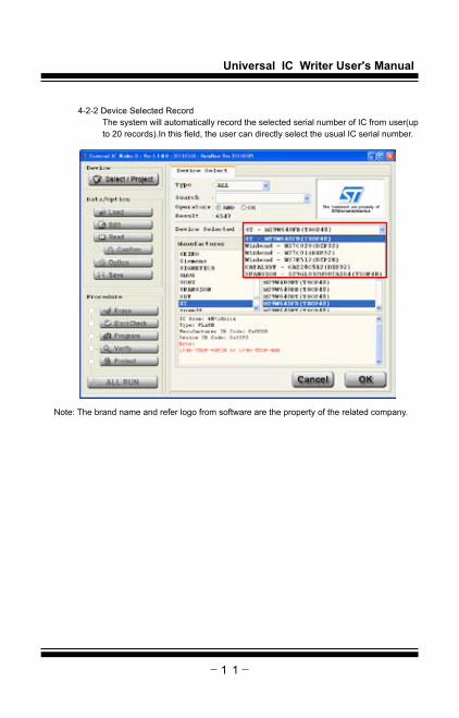
4-2-2 Device Selected RecordThe system will automatically record the selected serial number of IC from user(up to 20 records).In this field, the user can directly select the usual IC serial number.
Note: The brand name and refer logo from software are the property of the related company.

Universal IC Writer User's Manual
1 2
4-3 File LoadLoad the file to the data buffer as the user-specified file and format.
4-3-1 Load File PathThe path of programming, which can select the file downloaded or reselect by pressing "Browse" button.
4-3-2 File FormatSelect the programming format of files. If you are unsure about the file, we recommend using "Auto Detect" function.
4-3-3 Source SelectSet the loading scope of original file. The file data outside the scope is abandoned. Note the "Start Address" can't be larger than the "End Address".
4-3-4 Destination SelectAfter loading files, the data will be placed at the start address of the buffer.
4-3-5 "Fill Unused With" function is used to determine: When the file can not fully cover the IC, the information needed fill in rest space. The unchecked area will reserve last information.
Browse
Searching Records
Automatically adjust to IC's capacity
Fill the value of unset region of the data

Universal IC Writer User's Manual
1 3
4-4 Edit
4-4-1 Display Mode (8 Bits/16 Bits)Switch the data format: Byte (8 Bits) or Word (16 Bits)
4-4-2 View/Edit Mode View mode is just for displaying the data, therefore the state can not be changed. Only pressing the "Edit" can revise the data.To avoid the data in buffer being inadvertently changed, the default mode will be View mode.
View mode, the information can not be modified
8 Bits display mode
Edit Mode
Current address
16 Bits display mode
Data (16 hex mode)
Data (ASCII mode)

Universal IC Writer User's Manual
1 4
4-5 Option SettingThis page is related setting for software and processing IC. The page will change the state immediately when clicking, without pressing any confirm key.
4-5-1 General System Setting
1. Insert Detect:Before every IC processing, the system will check whether the IC is wrong-side, offset, empty inserted,or bad connection. If there's a problem, it will stop implementing follow-up actions. Before customers press Read, Confirm, Erase, Blank Check, Program, Verify, Protect, and ALL RUN keys for checking, the system had implemented this action.If customers didn't check it , the programmer would check whether IC is put in Socket, bad connection of pins, and empty inserted. It will no longer judge and stop follow-up actions. ※ If the item can not be checked , which represents the IC does not support this function.
2. Device ID Check:Checking the pending IC's ID after customers place the IC and before systems processes the IC. If the checking result is not corresponding with the IC data, the system will not implement follow-up actions. ※ If the item can not be checked, which represents the IC does not support the ID recognition function.
3. Confirm Error List :When the item is not checked, pressing "Confirm" will just compare that whether the data is the same as buffer's one.If the result is right, it will show "Pass". Oppositely it will show "Fail".When checking the items, the system will list the the different value between the buffer and IC internal data in the message field. The list behind the option is the error display , up to 999 lines.※When checking the"Confirm Error List", it will not compare the data of device option.
4. Programming area selection:Selecting programming and comparing area of IC. The main memory zone will be enforced programming;however other zones can be checked at customer's own. ※"Read"- All data will be read back to the computer, and placed in the buffer.
5. Message column related settings: Setting the line's number of messages(1000-5000lines).When messages reach setting lines, customers can choose "Auto Clear and Save" or "Auto Clear".
6. Device Insert Detect:The machine will implement related self-tests and show the detailed results in the message column. ※Users can not put any IC or adapter on the sockets of the machine during test.
1 2 3
4
5
6

Universal IC Writer User's Manual
1 5
4-5-2 Device Check
This page is about the related parameters setting of the IC. The type, quantity and form will be changed from different IC.
All of the setting parameters are programed to IC when programming.However the protect-related setting is excluded, such as: Write Protect or Read Protect. The protective setting are all programmed to DUT IC under protect actions.
※If there is no screen displaying, it means that the IC doesn't have related-parameters setting.
Universal IC Writer User's Manual
1 6
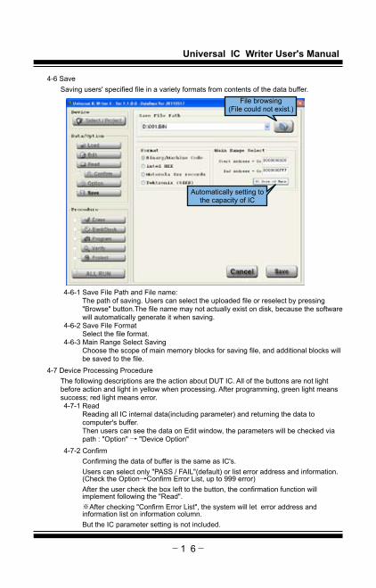
4-6 SaveSaving users' specified file in a variety formats from contents of the data buffer.
4-6-1 Save File Path and File name:The path of saving. Users can select the uploaded file or reselect by pressing "Browse" button.The file name may not actually exist on disk, because the software will automatically generate it when saving.
4-6-2 Save File FormatSelect the file format.
4-6-3 Main Range Select SavingChoose the scope of main memory blocks for saving file, and additional blocks will be saved to the file.
4-7 Device Processing ProcedureThe following descriptions are the action about DUT IC. All of the buttons are not light before action and light in yellow when processing. After programming, green light means success; red light means error.4-7-1 Read
Reading all IC internal data(including parameter) and returning the data to computer's buffer.Then users can see the data on Edit window, the parameters will be checked via path : "Option" → "Device Option"
4-7-2 ConfirmConfirming the data of buffer is the same as IC's. Users can select only "PASS / FAIL"(default) or list error address and information.(Check the Option→Confirm Error List, up to 999 error) After the user check the box left to the button, the confirmation function will implement following the "Read".※After checking "Confirm Error List", the system will let error address and information list on information column.But the IC parameter setting is not included.
File browsing (File could not exist.)
Automatically setting to the capacity of IC

Universal IC Writer User's Manual
1 7
4-7-3 EraseErase all the internal data of DUT IC to default setting(Including protection setting).Unless the user confirms the DUT IC is new or empty, we suggest adding this function when programming.Besides, some ICs' protect function is only for one time. It may cause unable to erase or re-program.※ If the IC is OTP or EPROM type, the erase function is unworkable.※ There are default information in kinds of IC(MPU or NAND FLASH,etc.) Erase function will not erase that possibly. Or the data will be written-back after erasing. It is based on whether the IC permits programmer to implement the function.
4-7-4 Blank CheckCheck the memory and all settings in IC are default.
4-7-5 ProgramProgramming the buffer's data and related settings to DUT IC.
4-7-6 VerifyCheck whether programmed data and related settings in IC is the same as buffer's. 4-7-7 ProtectProtect settings of DUT IC:Due to the difference of DUT IC's type and Option settings.It may cause DUT IC change to protection status(unable to overwrite and read information)※ Whether the DUT IC could prevent overwriting, reading or without any protection is decided by IC itself. If user's IC is without any protective function, the system will close "Protect" procedure.
4-7-8 ALL RUNAutomatically processing below 5 checked procedure after pressing it. If there's any procedure failed, the system will stop. And no longer implementing. The results will be listed in statics.※This process does not contain reading and confirming the IC information
Indicator of the action
Action Normal(No action) Action Pass Fail[Read]
[Confirm]
[Erase]
[BlankCheck]
[Program]
[Verify]
[Protect]
[ALL RUN] Null

Universal IC Writer User's Manual
1 8
Chapter 5 Simple Operating Practicee.g.1.Programming the MCU from data of computer, and adding protection on IC.
1.Click button on the top left to enter "Device Select" page. Then input searching keywords "AT89C51", the "Manufacturer" column will list possible companies. If there are over one manufacturer listing, you can select from that. On the top left side,"Parts Number" column lists the serial number of the IC. You can click what you need and check related messages and precautions. Finally press to finish selecting.。
2. After the system settings are finished. Sometimes it will appear message window according to the characteristics of the IC. Remind you that the selected IC's additional information blocks or parameters settings need be reload or set. When you change the new IC serial number, all the parameters automatically return to default. That is to say, if you want to program the MCU data to another different serial number MCU.(Including same serial number, but different package)You have to check other additional data blocks and reset the device parameters.

Universal IC Writer User's Manual
1 9
3. Click the key on top left to enter the "Load File" page. Then clicking the button on the top right folder , selecting the file you need load. In this example the file format to be loaded is "intel HEX", you can set in "Format" column. You can also select "Auto Detect",let the system automatically determine. After confirming the file contents, file name and format are correct, pressing lower right button to load the file.
4. After loading files completely, users can check the value at "Check Sum".Due to some IC's "Check Sum" calculation is special. You need select the IC and load the file under the state of connecting with programmer.

Universal IC Writer User's Manual
2 0
5.Put the IC on the programmer's socket. The IC's gap is upward. The bottom of the IC aligns with the bottom of the socket. Confirm the IC is placed , then put the socket's stick down. The IC will be steadily fixed.
6.In this example, users need do Protect process to this IC. Because this IC has a variety of protection. Please click left button to enter "Device Option'\'Lock Bit Option" page. Selecting settings according to your needs. After confirming, press bottom right to finish.
If you do not process this procedure, and clicking "procedure" then selecting "Protect". The programmer will not correctly protect your IC. Meanwhile, it will also cause error.

Universal IC Writer User's Manual
2 1
6.Back to the main menu, check the lower left button at "Procedure" column. Then checking other procedures according to your needs.
7.Finally confirming the IC is placed steadily again and checking the serial number.After "Check Sum" procedure is correct, then clicking button. The programmer will process the IC based on your selection. Note: In the process of implementing the IC. Never unplugging USB cable or touching socket components by hands. Switching open socket's stick is also prohibited. Upon completing all the process, the result will be displayed by "PASS/FAIL".If some problems occur in the process, the system will stop. Then error parts will change into red.Supposing the errors are placement or ID checking of the IC, it will display in message column. You can repeat the procedure after solving the problem.

Universal IC Writer User's Manual
2 2
e.g.2.Reading internal memory data of the IC, and saving it by Binary Format. 1. Click the top left button to enter "Device Select" page. Enter
searching word of the IC in "Search" column. Clicking the manufacturers and serial number of the IC. Finally clicking to finish.
2. The example is to read a NOR FLASH in TSOP package. Please use the appropriate adapter. When inserting the adapter, the user need align it with the adapter to the bottom of the Socket. The adapter is usually marked "1" on the corner of the pin. Please place it toward top left side.
And please follow description on the socket to place the IC.
Universal IC Writer User's Manual
2 3
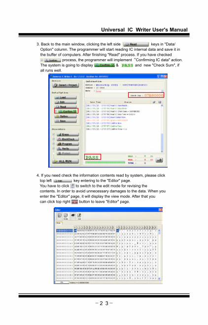
3. Back to the main window, clicking the left side keys in "Data/Option" column. The programmer will start reading IC internal data and save it in the buffer of computers. After finishing "Read" process. If you have checked process, the programmer will implement“Confirming IC data" action. The system is going to display & and new "Check Sum", if all runs well.
4. If you need check the information contents read by system, please click top left key entering to the "Editor" page. You have to click to switch to the edit mode for revising the contents. In order to avoid unnecessary damages to the data. When you enter the "Editor" page, it will display the view mode. After that you can click top right button to leave "Editor" page.

Universal IC Writer User's Manual
2 4
5. Click top left button to enter " Save File" pages. Then clicking top right button. Selecting contents you want to save the file and clicking the file or typing a file name. Completed entering contents and name of the file, pressing the lower right button back to "Save File" page. Selecting file format again; checking all the settings are correct, finally clicking button to save.
e.g.3.Using system's self detecting function to detect hardware of programmer.1. Remove the IC or adapters on the programmer's socket carefully.
Or it may cause wrong checking or damaging your programmer. 2. Please click the left button to enter "General" page. After checking there's
not any IC or devices on the Socket, clicking bottom right button. And then clicking confirm key in reminder window , the system will start to test.
3. After finishing the self-test, there will be a prompt window.Detailed results will be displayed in the message window.

Universal IC Writer User's Manual
2 5
3. You can scroll to check or click button. Let message convert to text file.

Universal IC Writer User's Manual
2 6
Chapter 6 Troubleshooting1 Status Description :
Software and driver can not be settled. The soft can not run or abnormally run.
Troubleshooting : Please use "Administrator" permission to log in and then run the driver's installation or software implementation.
2 Status Description : Unknown reasons cause abnormal operation of the software.
Troubleshooting : Restart the software or reconnect USB cable, then try again.
3 Status Description : Failure detection of the IC and couldn't be programmed. Appears "Insert Detect Empty!"、"Insert Detect Fail!"、"ID Check Fail!" and other error messages.
Troubleshooting :1.Please confirm whether the IC is placed correctly? Are the direction and position right?2.Checking the IC pins are neat and clean? We suggest using new IC for programming, do not use old ones. Avoid shortening the life of the adapter.3.Please confirm whether the adapter is right? socket is old? or overused? The adapters are consumables. Please purchase a new one if it is unable to use.
4 Status Description : Software can not be connected to the machine.(Message column shows "Not Detect Universal IC Writer II!" message)
Troubleshooting :1. Check whether the programmer is used standard Y-USB cable and connected to the computer's two USB port.2. Check whether the driver is installed correctly.3. Check whether the USB Port is USB 2.0 High Speed interface.
5 Status Description : After connecting the machine, the LED is not light.Troubleshooting :1. Check whether the driver is installed correctly.2. Check whether the programmer is used standard Y-USB cable and connected to the computer's two USB port.
6 Status Description : The LED flashes twice then goes out. After computer connects the programmer.
Troubleshooting :1. Check whether the connect software is not open.2. Check whether the driver is installed correctly.3. Check whether the USB Port is USB 2.0 High Speed interface.

Universal IC Writer User's Manual
2 7
7 Status Description : When software appears below warning message: It means the power supplied by USB port is not enough. Click "Cancel" can ignore that, but it may cause following procedure wrong.
Troubleshooting :1. Use standard Y-USB cable and connected to the computer's two USB port.2. Change another USB port.3. Connect the programmer and computer through USB Hub, besides the USB Hub must be powered by external power supplier. (5V/1A above)
8 Status Description : Self-test function (Self-Test) can not pass all the test.
Troubleshooting : Please check whether there is any IC or adapter on programmer's socket. If it still failed, please send the programmer and self-test messages' file back to us.