Embed Size (px)
Citation preview
Lecture 4:Layers & Framing
CSE 123: Computer Networks Stefan Savage
HW 1 out Today, due 4/15 Proj 1 out Today, due 5/1
Some quick comments aboutthe project
● Accounts ◆ Late, but should be set up shortly
● Ethics ◆ Words of warning – don’t copy, don’t cheat
CSE 123 – Lecture 3: Framing 2
3
Lecture 4 Overview
● Layering
● Framing ◆ Stuffing
CSE 123 – Lecture 4: Framing
Problem● Communications is complicated
◆ Modulation and encoding bits ◆ Splitting sequences of bits into packets ◆ Fixing errors ◆ Controlling access to network ◆ Routing ◆ Recovering from lost messages ◆ Etc….
● Really hard to think about all of this and get it right ● Not all applications need all of it ● How to achieve interoperability?
CSE 123 – Lecture 3: Framing 4
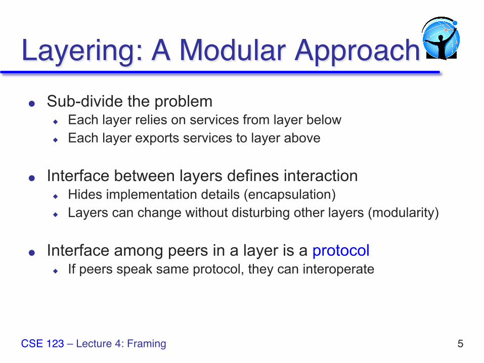
Layering: A Modular Approach● Sub-divide the problem
◆ Each layer relies on services from layer below ◆ Each layer exports services to layer above
● Interface between layers defines interaction ◆ Hides implementation details (encapsulation) ◆ Layers can change without disturbing other layers (modularity)
● Interface among peers in a layer is a protocol ◆ If peers speak same protocol, they can interoperate
5 CSE 123 – Lecture 4: Framing
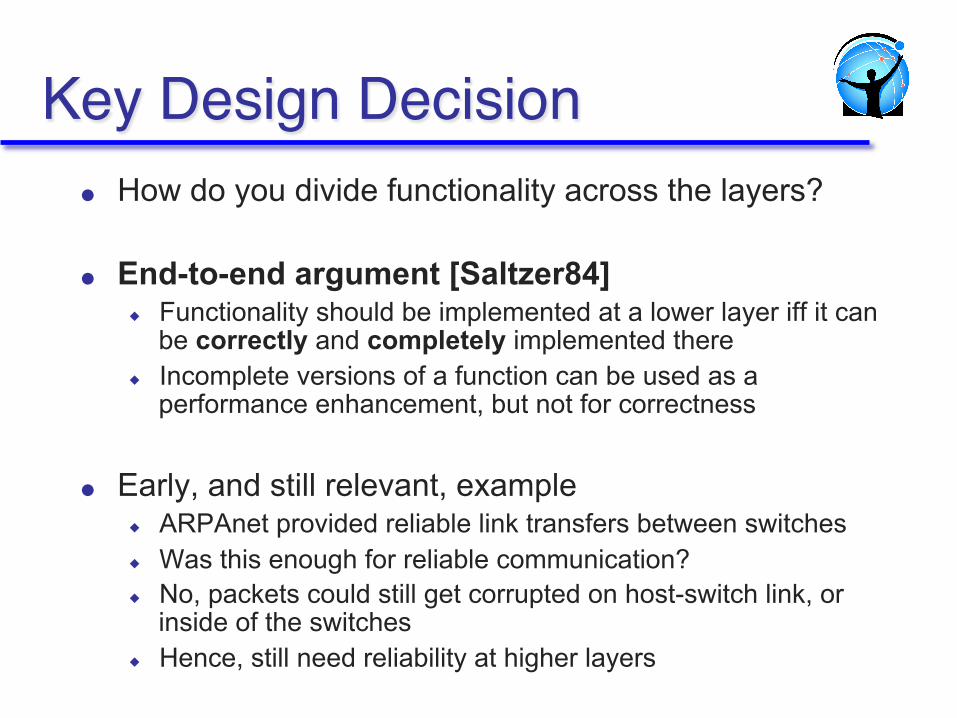
Key Design Decision● How do you divide functionality across the layers?
● End-to-end argument [Saltzer84] ◆ Functionality should be implemented at a lower layer iff it can
be correctly and completely implemented there ◆ Incomplete versions of a function can be used as a
performance enhancement, but not for correctness
● Early, and still relevant, example ◆ ARPAnet provided reliable link transfers between switches ◆ Was this enough for reliable communication? ◆ No, packets could still get corrupted on host-switch link, or
inside of the switches ◆ Hence, still need reliability at higher layers
Protocol Standardization● Communicating hosts speaking the same protocol
◆ Standardization to enable multiple implementations ◆ Or, the same folks have to write all the software
● Internet Engineering Task Force ◆ Based on working groups that focus on specific issues ◆ Produces “Request For Comments” (RFCs)
» Rough consensus and running code » After enough time passes, promoted to Internet Standards
● Other standards bodies exist ◆ ISO, ITU, IEEE, etc.
7 CSE 123 – Lecture 4: Framing
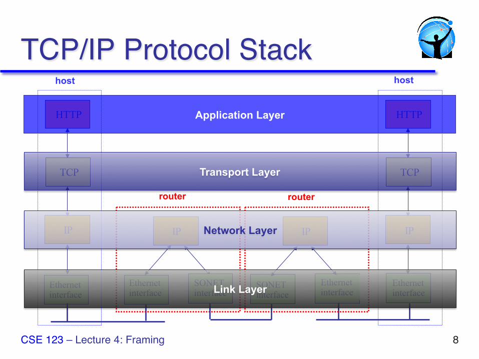
TCP/IP Protocol Stack
HTTP
TCP
IP
Ethernet interface
HTTP
TCP
IP
Ethernet interface
IP IP
Ethernet interface
Ethernet interface
SONET interface
SONET interface
host host
router router
8
Application Layer
Transport Layer
Network Layer
Link Layer
CSE 123 – Lecture 4: Framing
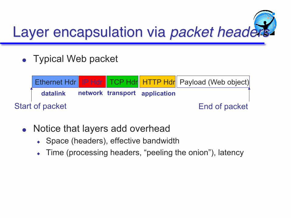
Layer encapsulation via packet headers● Typical Web packet
● Notice that layers add overhead ◆ Space (headers), effective bandwidth ◆ Time (processing headers, “peeling the onion”), latency
IP Hdr Payload (Web object) TCP Hdr HTTP Hdr Ethernet Hdr
Start of packet End of packet
datalink network transport application
Data Link
Physical
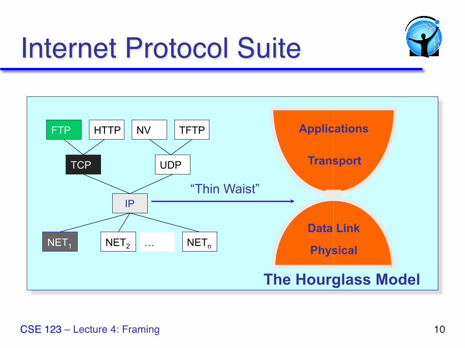
Applications
The Hourglass Model
“Thin Waist”
FTP HTTP TFTP NV
TCP UDP
IP
NET1 NET2 NETn …
10
Transport
Internet Protocol Suite
CSE 123 – Lecture 4: Framing
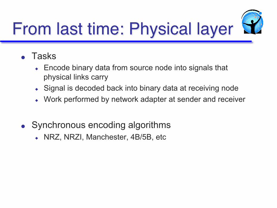
From last time: Physical layer● Tasks
◆ Encode binary data from source node into signals that physical links carry
◆ Signal is decoded back into binary data at receiving node ◆ Work performed by network adapter at sender and receiver
● Synchronous encoding algorithms ◆ NRZ, NRZI, Manchester, 4B/5B, etc
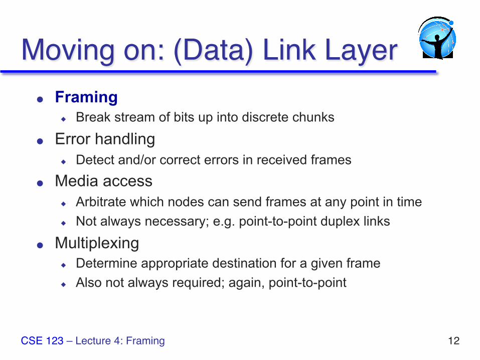
Moving on: (Data) Link Layer● Framing
◆ Break stream of bits up into discrete chunks
● Error handling ◆ Detect and/or correct errors in received frames
● Media access ◆ Arbitrate which nodes can send frames at any point in time ◆ Not always necessary; e.g. point-to-point duplex links
● Multiplexing ◆ Determine appropriate destination for a given frame ◆ Also not always required; again, point-to-point
12 CSE 123 – Lecture 4: Framing
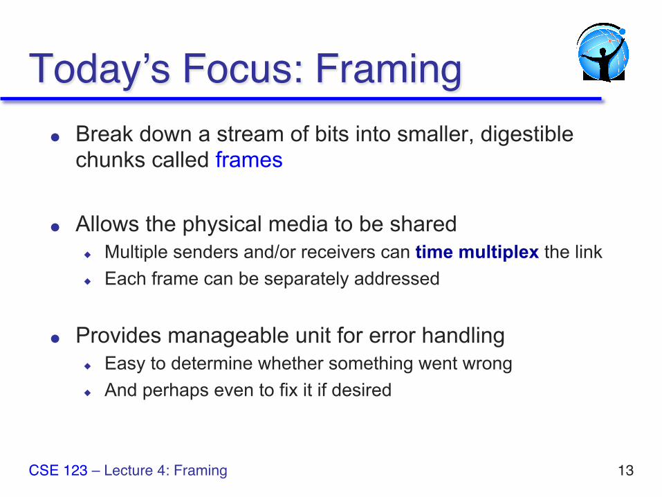
Today’s Focus: Framing● Break down a stream of bits into smaller, digestible
chunks called frames
● Allows the physical media to be shared ◆ Multiple senders and/or receivers can time multiplex the link ◆ Each frame can be separately addressed
● Provides manageable unit for error handling ◆ Easy to determine whether something went wrong ◆ And perhaps even to fix it if desired
CSE 123 – Lecture 4: Framing 13
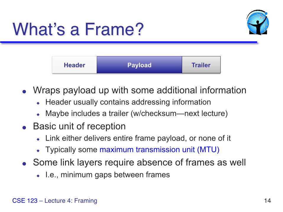
What’s a Frame?
● Wraps payload up with some additional information ◆ Header usually contains addressing information ◆ Maybe includes a trailer (w/checksum—next lecture)
● Basic unit of reception ◆ Link either delivers entire frame payload, or none of it ◆ Typically some maximum transmission unit (MTU)
● Some link layers require absence of frames as well ◆ I.e., minimum gaps between frames
CSE 123 – Lecture 4: Framing 14
Payload Header Trailer
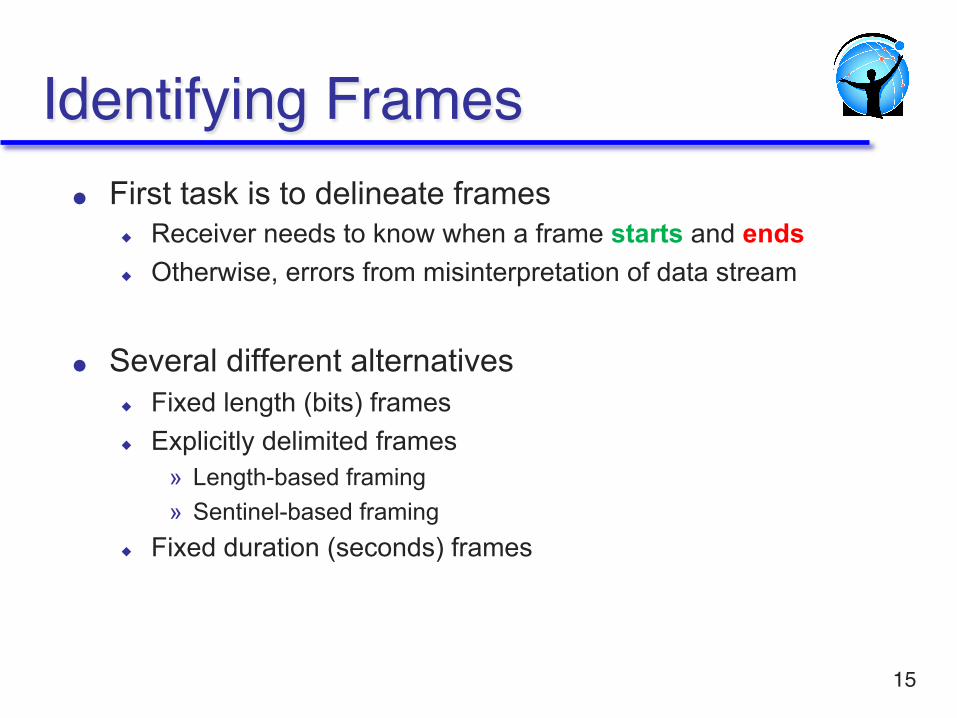
Identifying Frames● First task is to delineate frames
◆ Receiver needs to know when a frame starts and ends ◆ Otherwise, errors from misinterpretation of data stream
● Several different alternatives ◆ Fixed length (bits) frames ◆ Explicitly delimited frames
» Length-based framing » Sentinel-based framing
◆ Fixed duration (seconds) frames
15
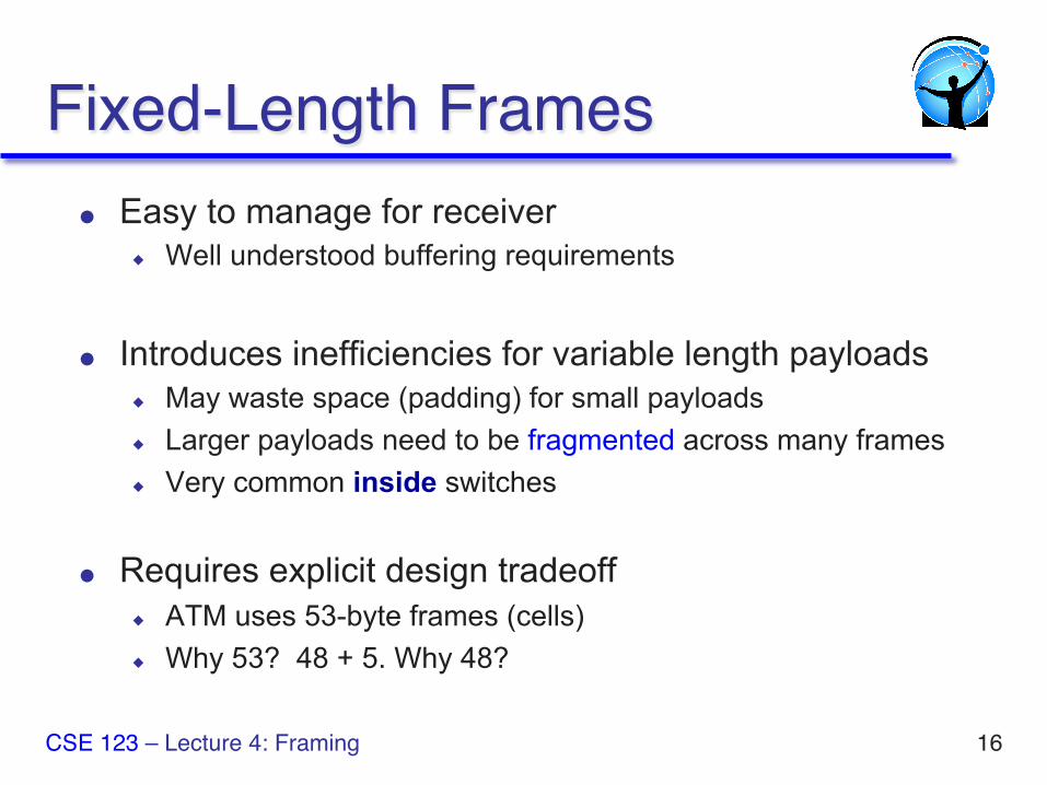
Fixed-Length Frames● Easy to manage for receiver
◆ Well understood buffering requirements
● Introduces inefficiencies for variable length payloads ◆ May waste space (padding) for small payloads ◆ Larger payloads need to be fragmented across many frames ◆ Very common inside switches
● Requires explicit design tradeoff ◆ ATM uses 53-byte frames (cells) ◆ Why 53? 48 + 5. Why 48?
CSE 123 – Lecture 4: Framing 16
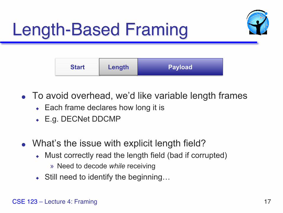
Length-Based Framing
● To avoid overhead, we’d like variable length frames ◆ Each frame declares how long it is ◆ E.g. DECNet DDCMP
● What’s the issue with explicit length field? ◆ Must correctly read the length field (bad if corrupted)
» Need to decode while receiving ◆ Still need to identify the beginning…
CSE 123 – Lecture 4: Framing 17
Payload Start Length
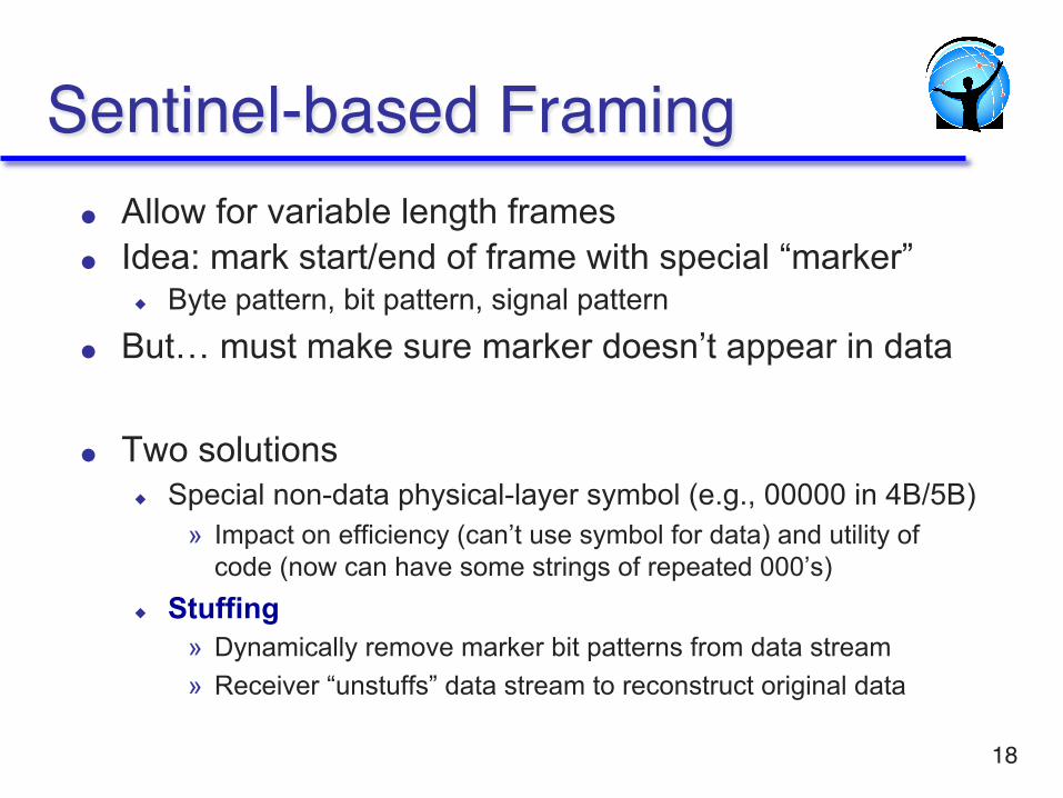
Sentinel-based Framing● Allow for variable length frames ● Idea: mark start/end of frame with special “marker”
◆ Byte pattern, bit pattern, signal pattern ● But… must make sure marker doesn’t appear in data ● Two solutions
◆ Special non-data physical-layer symbol (e.g., 00000 in 4B/5B) » Impact on efficiency (can’t use symbol for data) and utility of
code (now can have some strings of repeated 000’s) ◆ Stuffing
» Dynamically remove marker bit patterns from data stream » Receiver “unstuffs” data stream to reconstruct original data
18
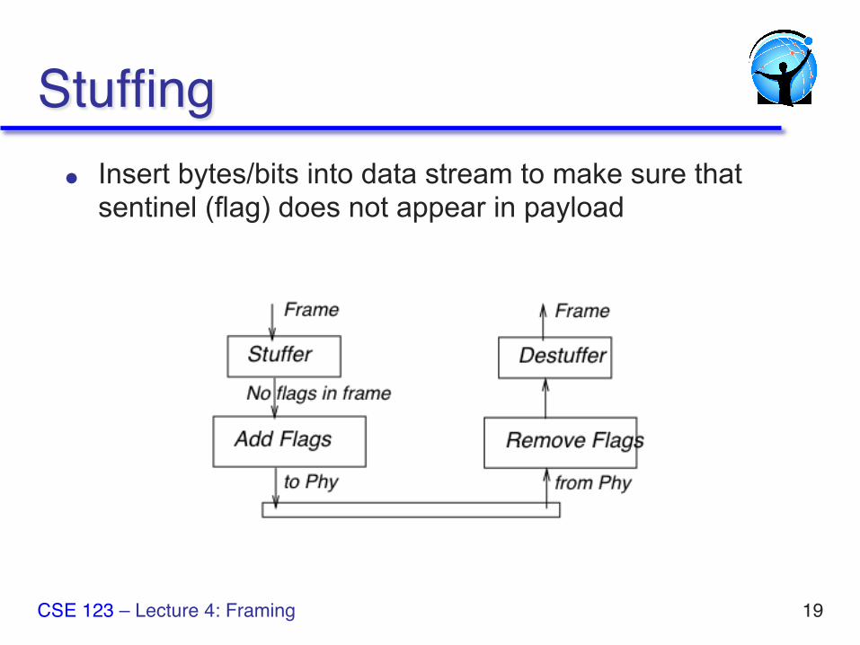
Stuffing● Insert bytes/bits into data stream to make sure that
sentinel (flag) does not appear in payload
CSE 123 – Lecture 4: Framing 19
Bit-level Stuffing
20
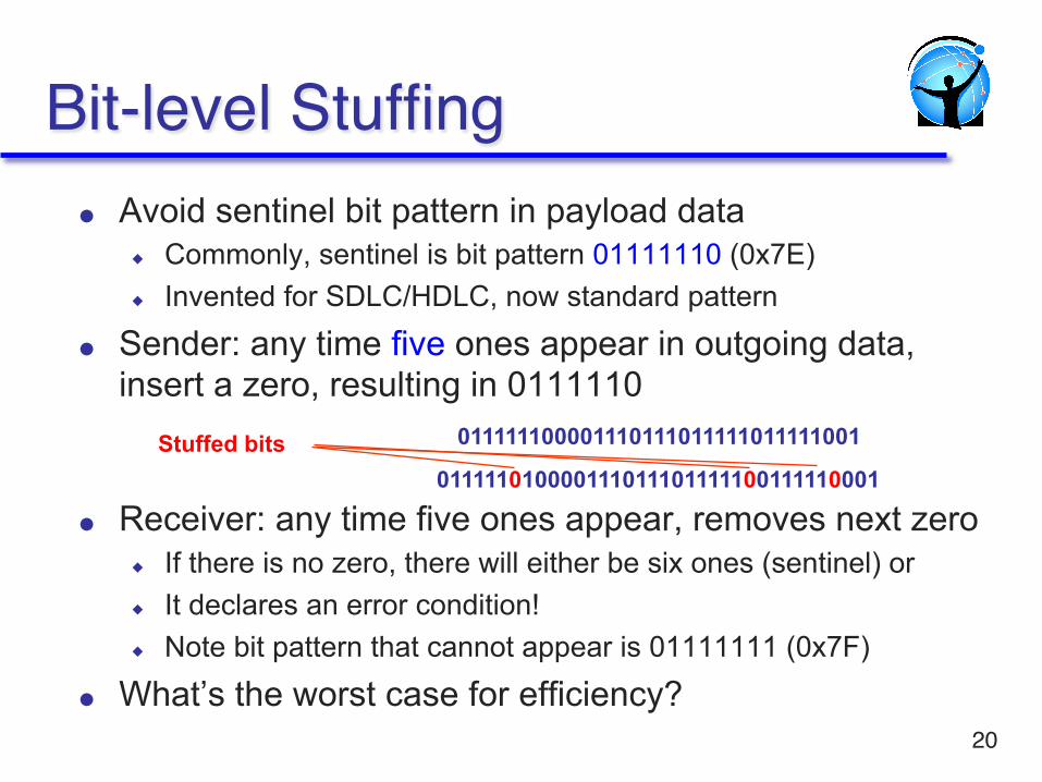
● Avoid sentinel bit pattern in payload data ◆ Commonly, sentinel is bit pattern 01111110 (0x7E) ◆ Invented for SDLC/HDLC, now standard pattern
● Sender: any time five ones appear in outgoing data, insert a zero, resulting in 0111110
● Receiver: any time five ones appear, removes next zero ◆ If there is no zero, there will either be six ones (sentinel) or ◆ It declares an error condition! ◆ Note bit pattern that cannot appear is 01111111 (0x7F)
● What’s the worst case for efficiency?
011111100001110111011111011111001
011111010000111011101111100111110001 Stuffed bits
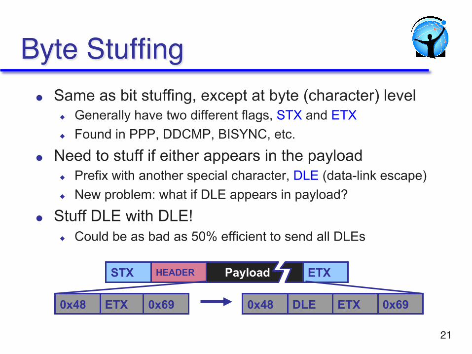
Byte Stuffing● Same as bit stuffing, except at byte (character) level
◆ Generally have two different flags, STX and ETX ◆ Found in PPP, DDCMP, BISYNC, etc.
● Need to stuff if either appears in the payload ◆ Prefix with another special character, DLE (data-link escape) ◆ New problem: what if DLE appears in payload?
● Stuff DLE with DLE! ◆ Could be as bad as 50% efficient to send all DLEs
21
ETX
STX ETX Payload HEADER
0x48 0x69 ETX DLE 0x69 0x48
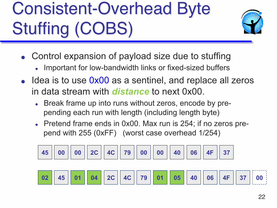
Consistent-Overhead Byte Stuffing (COBS)
22
● Control expansion of payload size due to stuffing ◆ Important for low-bandwidth links or fixed-sized buffers
● Idea is to use 0x00 as a sentinel, and replace all zeros in data stream with distance to next 0x00. ◆ Break frame up into runs without zeros, encode by pre-
pending each run with length (including length byte) ◆ Pretend frame ends in 0x00. Max run is 254; if no zeros pre-
pend with 255 (0xFF) (worst case overhead 1/254)
45 00 00 2C 4C 79 00 00 40 06 4F 37
02 45 01 04 2C 4C 79 01 05 40 06 4F 37 00
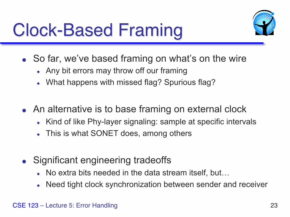
Clock-Based Framing● So far, we’ve based framing on what’s on the wire
◆ Any bit errors may throw off our framing ◆ What happens with missed flag? Spurious flag?
● An alternative is to base framing on external clock ◆ Kind of like Phy-layer signaling: sample at specific intervals ◆ This is what SONET does, among others
● Significant engineering tradeoffs ◆ No extra bits needed in the data stream itself, but… ◆ Need tight clock synchronization between sender and receiver
23 CSE 123 – Lecture 5: Error Handling
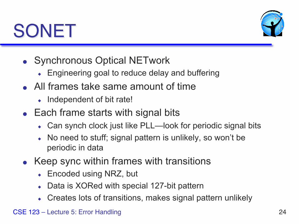
SONET● Synchronous Optical NETwork
◆ Engineering goal to reduce delay and buffering
● All frames take same amount of time ◆ Independent of bit rate!
● Each frame starts with signal bits ◆ Can synch clock just like PLL—look for periodic signal bits ◆ No need to stuff; signal pattern is unlikely, so won’t be
periodic in data
● Keep sync within frames with transitions ◆ Encoded using NRZ, but ◆ Data is XORed with special 127-bit pattern ◆ Creates lots of transitions, makes signal pattern unlikely
24 CSE 123 – Lecture 5: Error Handling
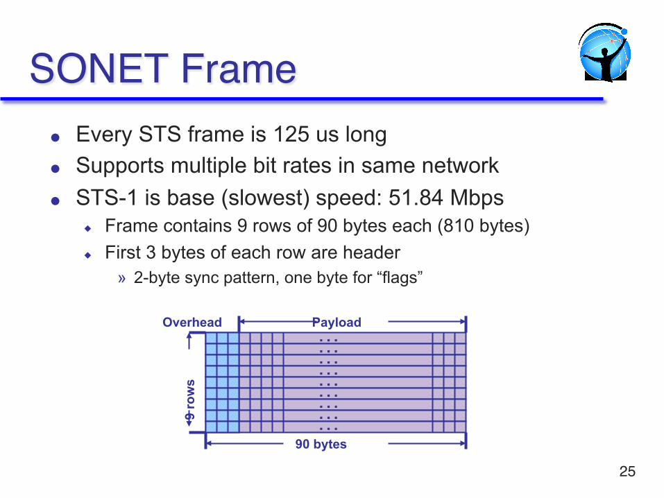
SONET Frame● Every STS frame is 125 us long ● Supports multiple bit rates in same network ● STS-1 is base (slowest) speed: 51.84 Mbps
◆ Frame contains 9 rows of 90 bytes each (810 bytes) ◆ First 3 bytes of each row are header
» 2-byte sync pattern, one byte for “flags”
25
… … … … … … … … …
Overhead Payload
9 ro
ws
90 bytes
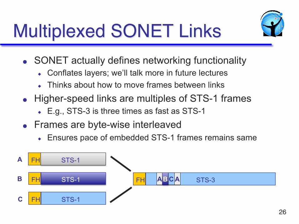
Multiplexed SONET Links● SONET actually defines networking functionality
◆ Conflates layers; we’ll talk more in future lectures ◆ Thinks about how to move frames between links
● Higher-speed links are multiples of STS-1 frames ◆ E.g., STS-3 is three times as fast as STS-1
● Frames are byte-wise interleaved ◆ Ensures pace of embedded STS-1 frames remains same
26
STS-1 FH
STS-1 FH
STS-1 FH
STS-3 FH
A
B
C
A A B C
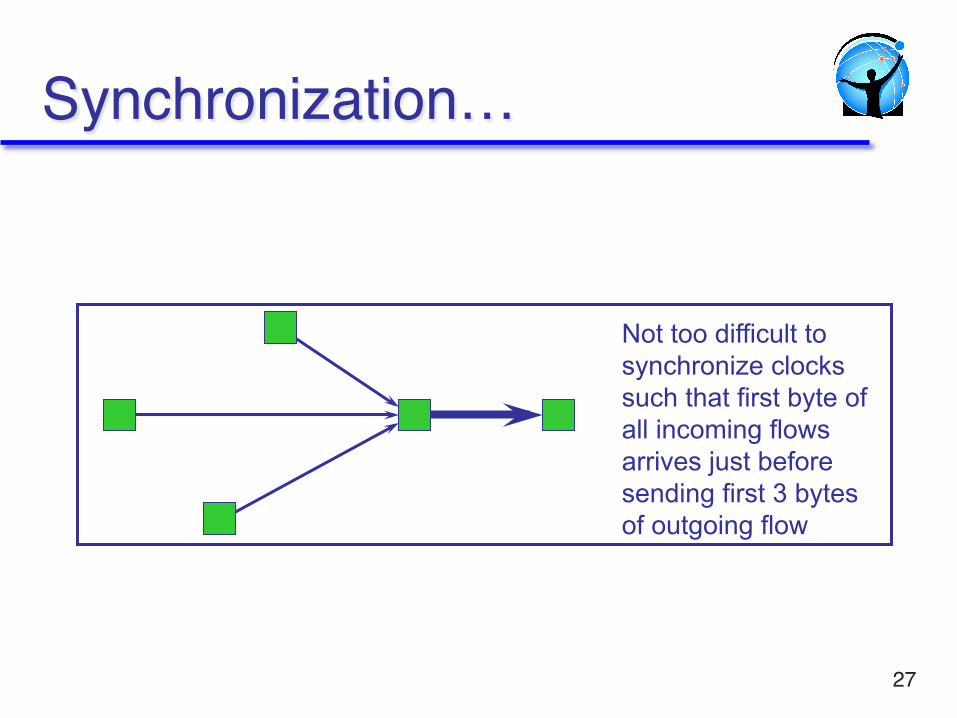
Synchronization…
27
Not too difficult to synchronize clocks such that first byte of all incoming flows arrives just before sending first 3 bytes of outgoing flow
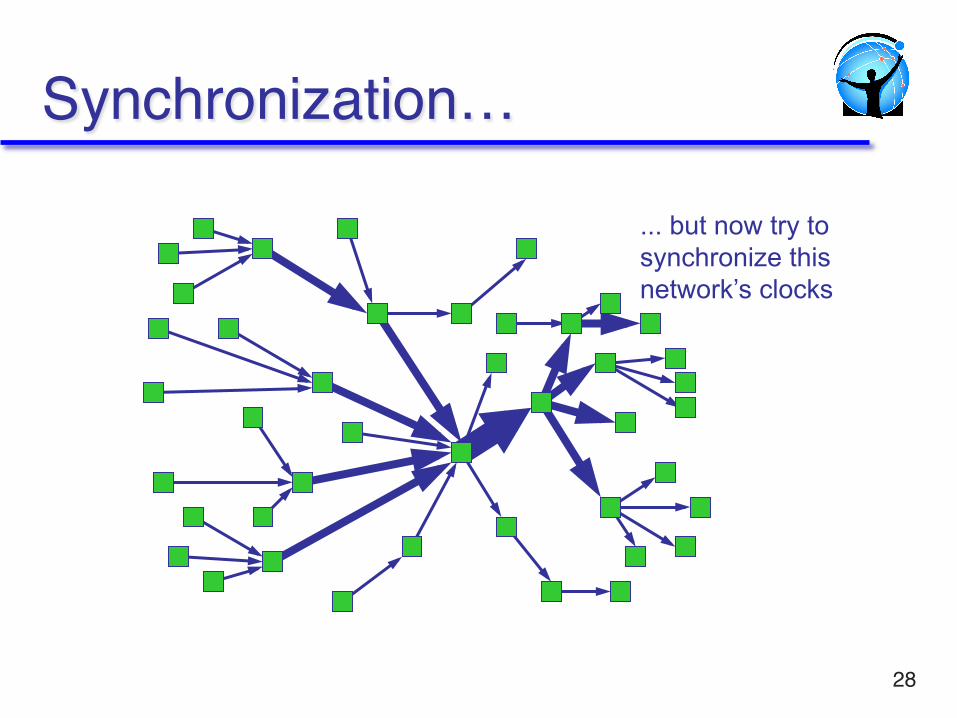
Synchronization…
28
... but now try to synchronize this network’s clocks
CSE 123 Lecture 3 – Framing and Error Control
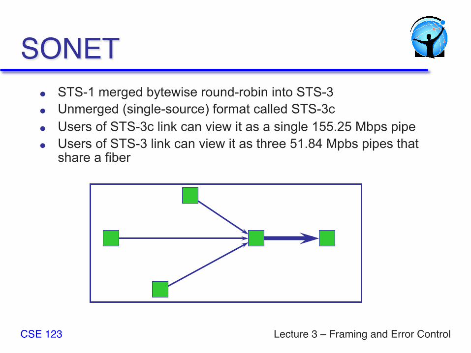
SONET● STS-1 merged bytewise round-robin into STS-3 ● Unmerged (single-source) format called STS-3c ● Users of STS-3c link can view it as a single 155.25 Mbps pipe ● Users of STS-3 link can view it as three 51.84 Mpbs pipes that
share a fiber
For next class● Next class: error detection
● Read 2.4
● Start going on HW 1
● Take a look at Project 1
CSE 123 – Lecture 3: Framing 30