Embed Size (px)
Citation preview


Andrew SherarMarch, 2015
Dimming LEDs

Confidential Dynalite Training, July 09, 2012
Agenda
3
Leading Edge dimmers
Trailing Edge dimmer
LED constant current Drivers
DALI/1-10VDC controls
DMX512
Retrofit LED solutions

Confidential Dynalite Training, July 09, 2012
Retrofit
Retrofit
AS3000 dictates that traditional MR16 50W lamps have transformer per lamp.
This is not suitable for retrofit LEDs. Typical retrofit LEDs are 7-10W in power consumption.
Electronic transformers have minimum load requirements of 20W.
Result is you need 3 LED retrofits per electronic transformer to even switch reliably.
Dimming performance is non linear & poor.

Confidential Dynalite Training, July 09, 2012
Leading Edge Phase ControlA
N
CONTROL
on
on
on
offoff
off
off
Most traditional form of dimmer
Simple, cost effective and efficient
Used with resistive and inductive loads
Examples:
- Incandescent / Mains Voltage - Low Voltage fittings with inductive transformers- Some LV fittings with
electronic transformers
Most popular form of dimming
Leading Edge

Confidential Dynalite Training, July 09, 2012
Leading Edge Phase ControlA
N
CONTROL
on
on
on
offoff
off
off
Series inductor used to create “rise time” to avoid incandescent lamps singing when dimmed.
Typical stage & studio dimmers have 400uS rise time.
Philips Dynalite “Big Box” have 200uS rise time
Philips Dynalite Din Rail have in the order of 30uS rise time
The larger the rise time, the better performance for incandescent lamps but worse for LEDs.
This is also true for MR16 lamps utilising electronic transformers.
Leading Edge

Confidential Dynalite Training, July 09, 2012
Typical Leading Edge Dimming
Leading Edge
Typical dimming scenario above can be electrically modelled as below.

Confidential Dynalite Training, July 09, 2012Leading Edge
Typical Ringing exhibited by leading edge dimming into capacitive loads

Confidential Dynalite Training, July 09, 2012Leading Edge
LED – Dimming – How badly it can go wrong….
Typical high power LEDS fitted to leadingedge dimmer. Quantity of over 30 lampsrunning at 100%. All is well. Note poorpower factor
Dimmer is set to 70%. The capacitiveLEDs with influence from inductive choke& series circuit resistance create a tunedRLC ring circuit with the step voltagefrom the dimmer creating a ringovershoot 100 times per second. Most ofthese LEDs failed within 2 minutes.Peak Voltage -450V, Peak Current 42.5A

Confidential Dynalite Training, July 09, 2012Leading Edge
LED – Leading Edge Solutions.
DDLE801 Purpose built LED dimmerActive load per channelStill need to de-rate channelsSuperior mains tracking
DMAL120F Active LoadSuppresses circuit ringingProvides load when thyristor tuned off to discharge capacitors in LEDs.Also suitable for trailing edge dimmers

Confidential Dynalite Training, July 09, 2012Trailing Edge
Trailing Edge Phase Control
Rise time controlled by Sine Wave
Suitable for capacitive and resistive loads onlyExamples:
Incandescent/Mains VoltageLV fittings with electronic transformers
Not as common as leading edge phase controlMajor Benefit –quieter or more silent dimmingUses MOSFETS as dimming devices which are more frail to current & voltage surge when compared with thyristors.
on
on
on
A
N
CONTROL

Confidential Dynalite Training, July 09, 2012Constant Current
Constant Current Drivers – Phase Control
Many drivers available typically Osram, Diginet, Meanwell.Later generation have lower capacitance & can be suitable for both leading &trailing edge dimming.Far better performance on trailing edge.Are prone to mains disturbance (flicker, harmonics)Typically LED current is between 350 & 700mA

Confidential Dynalite Training, July 09, 2012Constant Current
Constant Current Drivers – Phase Control
Challenge for the driver is to have enough energy at low levels to keep thepower supply alive without creating increased capacitance.Waveform analyser has to allow for both leading & trailing edge.Some manufacturers such as Tridonic allow Trailing edge only.
Confidential Dynalite Training, July 09, 2012Constant Current
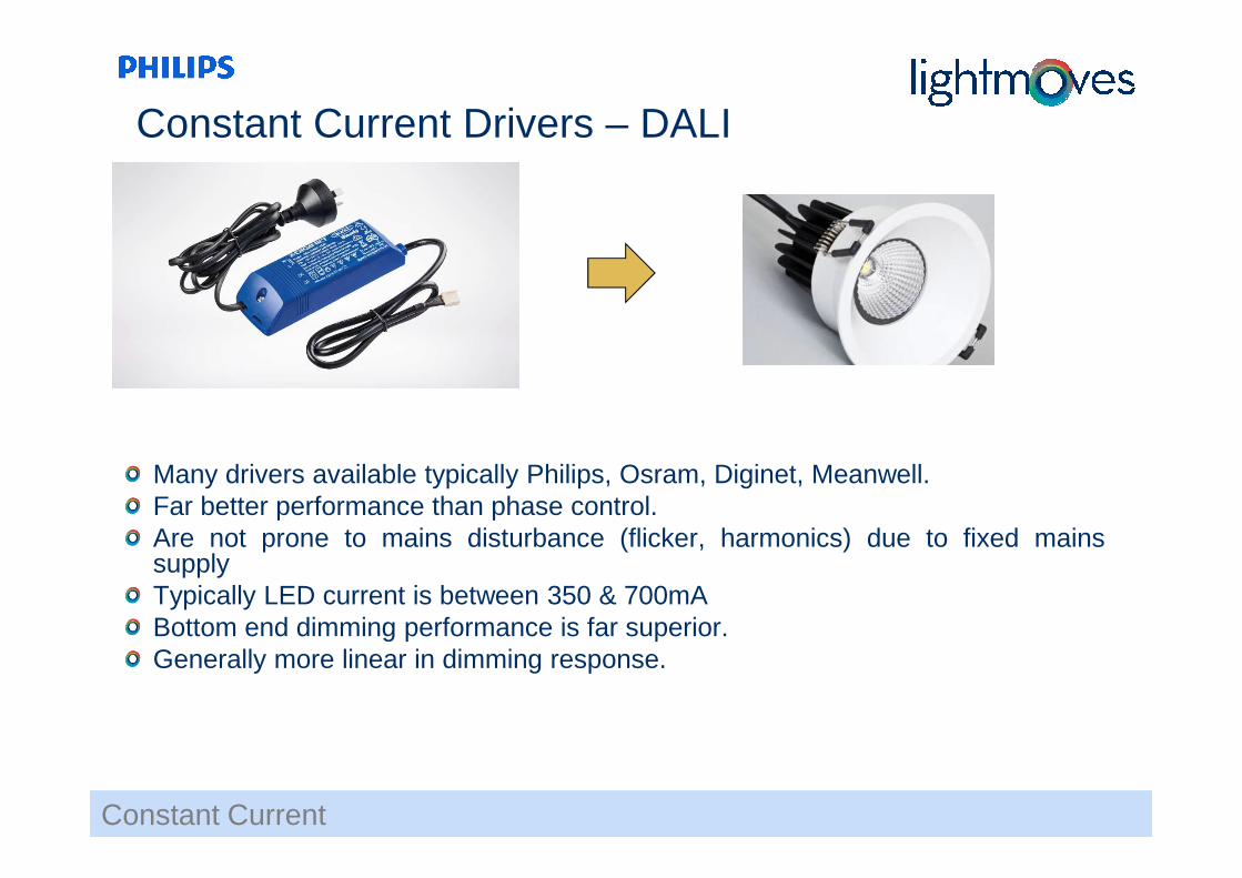
Constant Current Drivers – DALI
Many drivers available typically Philips, Osram, Diginet, Meanwell.Far better performance than phase control.Are not prone to mains disturbance (flicker, harmonics) due to fixed mainssupplyTypically LED current is between 350 & 700mABottom end dimming performance is far superior.Generally more linear in dimming response.

Confidential Dynalite Training, July 09, 2012DALI
Special Drivers – DALI
Great demand for “Tunable White” or RGB control.Tunable white used to enhance retail experience or replicate sun light (circadianrhythm) for office tenancy applications.One DALI address can have both intensity & colour selection controls.Part of DALI IEC 62386.Known as extension 209 or “type 8” control.

Confidential Dynalite Training, July 09, 20120-10VDC Control
LED 1(0) to 10v Control - Schematic
Be wary as many controls follow fluorescent ballast standard of 1-10VDC & willnot fully extinguish LEDs.Far better performance than phase control.Are not prone to mains disturbance (flicker, harmonics) due to fixed mainssupplyBe wary with SELV & ELV interfaces (DDMC802 with ballast card)

Confidential Dynalite Training, July 09, 2012
DMX512
Digital MultipleX communications protocol used mainly to control stage lightingMethod for controlling single controlling source to multiple locationsUses RS-485 Considered ‘Entertainment Technology’Useful for colour changes in LED control.Useful for large or dynamic control requirements as it is a very fast protocol controlling 512 channels.Many Dynalite devices compatible with DMX – transmit or receive.Preferred method of interface with Philips Color Kinetics.
DMX512
Confidential Dynalite Training, July 09, 2012Other Considerations
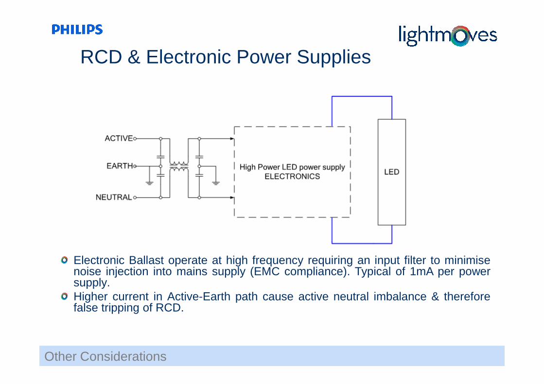
Electronic Ballast operate at high frequency requiring an input filter to minimisenoise injection into mains supply (EMC compliance). Typical of 1mA per powersupply.Higher current in Active-Earth path cause active neutral imbalance & thereforefalse tripping of RCD.
RCD & Electronic Power Supplies

Confidential Dynalite Training, July 09, 2012Other Considerations
Most mains supply is inherently noisy with the loss of sinusoidal current devices& most modern loads being active.Most typical current waveforms for LED devices are close to square wavecausing huge increases in odd harmonics.Power Quality standard is EN50160 which allows for +10/-15% flicker which issuitable for whitegoods. However LED flicker is noticeable at <3% mains flicker.So whilst mains may seem compliant by the outdated standard, much flicker canbe observed in retrofit & phase control LEDs.Installation may be fine when commissioned but flicker seems to increase after12-18 months. Typical complaint where the mains tends to increase content offlicker & harmonic distortion. Can be impacted by neighbors migrating to LEDs,Solar invertors, VFD’s etc.Leading edge dimming of capacitive loads reflects ringing onto the mains This isknown as “inter-harmonic” distortion & can be observed impacting 15th harmonic& above when testing with EN50160 test equipment.
Mains Harmonics & Flicker

Confidential Dynalite Training, July 09, 2012Other Considerations
Be wary of installing incandescent lamps on trailing edge dimmers wheninstalled filament up as per typical wall sconce.When filament fails, it normally drops onto the incoming connection pointscreating a huge inrush on the dimmer channel. This is too fast for the fuse toreact but will generally cause failure of the mosfets in the dimmer drive stage.
Incandescent 240VAC lamps on TE
Confidential Dynalite Training, July 09, 2012Load Information
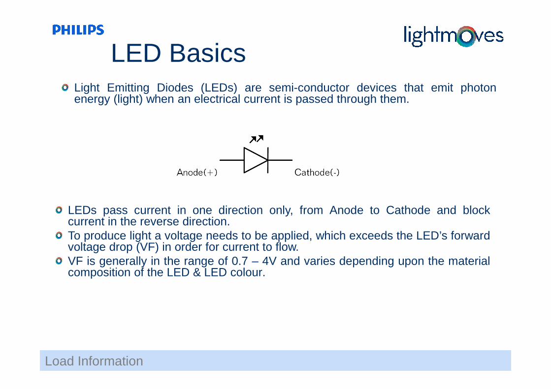
LEDs pass current in one direction only, from Anode to Cathode and blockcurrent in the reverse direction.To produce light a voltage needs to be applied, which exceeds the LED’s forwardvoltage drop (VF) in order for current to flow.VF is generally in the range of 0.7 – 4V and varies depending upon the materialcomposition of the LED & LED colour.
Light Emitting Diodes (LEDs) are semi-conductor devices that emit photonenergy (light) when an electrical current is passed through them.
LED Basics

LED DimmingThe most common way of dimming LED is Pulse Width Modulation (PWM).
This technique dims the LED by supplying the nominal current at a variable duty cycle, which enables a much greater dimming range. 50% brightness is achieved with a 50% duty cycle.
The frequency of the PWM is generally 100 Hz or greater, so that flicker is not discernable by the human eye.
The flicker can be seen in some non-broadcast quality cameras e.g., web cams
Load Information

The simplest method of driving an LED is to apply a DC voltage Vs to the LED with a resistor R in series. This will control the current and protect the LED. The forward current (IF) can be controlled by selecting a suitable resistor.Voltage mode LED fittings incorporating integral current regulation circuitry are designed for connection to a nominal voltage supply.
i.e.For a Luxeon® LED to run from a 12V supply at 350mA with a VF of 3V, it would require a resistor value of:R = (VS – VF)/IF = (12 – 3)/0.35 = 25.7 ohms
LED Voltage Mode
Load Information

LED Voltage Mode
Load Information

Confidential Dynalite Training, July 09, 2012
LED Voltage Mode - Considerations
Dynalite DDLEDC605 has 6 outputs of up to 5 amps with a total load of 20 amps 12 or 24 volt
It uses PWM to control light level
Power Supply must be matched to the LED
Useful for large loads of LED to be controlled together i.e. cove lighting
Useful where the designer has final say in LED selection and can ensure the product specified is delivered to the project to avoid incompatibility issues.
Load Information
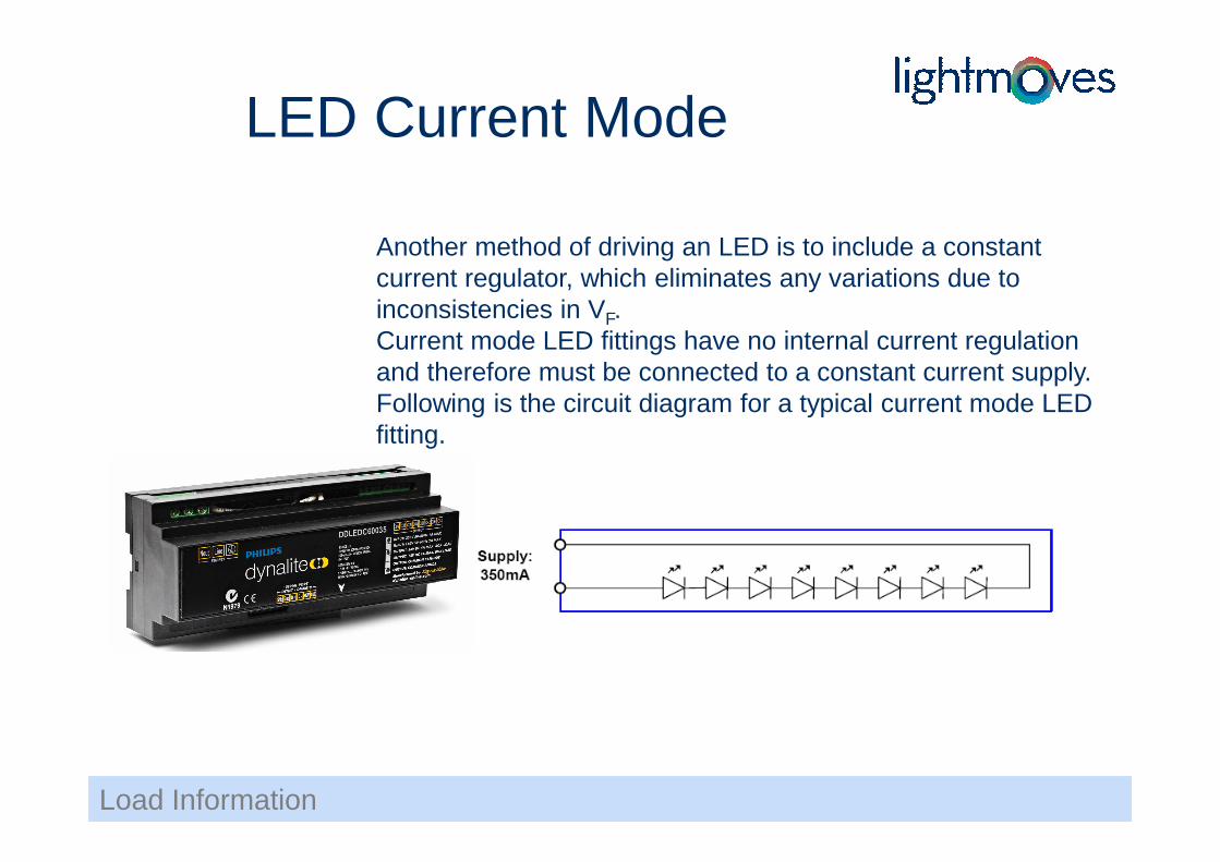
Another method of driving an LED is to include a constant current regulator, which eliminates any variations due to inconsistencies in VF.Current mode LED fittings have no internal current regulation and therefore must be connected to a constant current supply. Following is the circuit diagram for a typical current mode LED fitting.
LED Current Mode
Load Information

LED Current Mode
Load Information

Confidential Dynalite Training, July 09, 2012 28