Embed Size (px)
Citation preview
LED Juggling Balls with Pattern Detection
A Design Project Report
Presented to the School of Electrical and Computer Engineering of Cornell University
In Partial Fulfillment of the Requirements for the Degree of
Master of Engineering, Electrical and Computer Engineering
Submitted by
Jesse Haydn Checkla
With Co-Author: Alice Kassar
MEng Field Advisor: Dr. Bruce Land
Degree Date: May 2015

Abstract
Master of Engineering Program
School of Electrical and Computer Engineering
Cornell University
Design Project Report
Project Title: LED Juggling Balls with Pattern Detection
Authors: Jesse Checkla, Alice Kassar
Abstract:
Juggling patterns are often described by a numerical notation known as siteswap. Each number in a
siteswap represents the number of beats of each throw. While this notation is most often used for
communicating patterns, the underlying math can be used to achieve autonomous pattern detection.
Juggling balls were developed with an embedded system capable of determining the current juggling
siteswap and changing color accordingly. Internal accelerometers are used to record throws and catches
while wireless RF transceivers communicate these events. A microcontroller inside each ball processes
the accelerometer signal and prepares messages for transmission. An external microcontroller is
responsible for recording the individual ball states and passing them into MATLAB for pattern detection.
A signal is sent back to the balls to change the color of their internal LEDs based on this decision. Pattern
detection methods were simulated in software prior to implementation. Future improvements include a
reduction in the time-to-detection and removal of the external unit for increased portability. Possible
applications include use as a learning tool for the practicing juggler as well as increased entertainment
value for the performer. Beyond juggling, a multi-object system with pattern recognition and wireless
communication may have implications in areas like swarm-robotics.

Executive Summary Light-up LED balls are commonly used in performance juggling. The goal of this design project was to
create juggling balls capable of determining the pattern in which they are being juggled. Once a pattern
is detected, the balls will change their color using a set of internal LEDs. This method of visual feedback
offers both increased entertainment value and a useful training tool for the practicing juggler.
A variety of methods were considered for accomplishing the pattern detection. In the time domain, a
cross-correlation of the incoming waveform with existing recordings was theorized. Since juggling
patterns are periodic, a frequency-domain approach may also reliably distinguish patterns. The third and
preferred method utilizes a numerical notation called siteswap used to describe juggling patterns. Each
number in a siteswap represents the number of beats for each throw. While this notation is most often
used for communicating patterns, the underlying numerical sequence can be used to achieve
autonomous pattern detection.
The throws and catches for each ball are recorded to build a sequence. As this sequence is generated, an
algorithm runs to identify the pattern. Two separate detection algorithms were created. The preferred
method generates all possible sequences given the first event. As new events are recorded, sequences
are eliminated until sequences from just one pattern remain.
Each ball is outfitted with an accelerometer, an RF transceiver, and an Arduino microcontroller. Six LEDs
(2X red, green, blue) provide the visual feedback. A separate external receiver unit consisting of the
same transceiver and microcontroller is connected to a PC via USB. Events are detected by the
accelerometer, packaged by the microcontroller, and transmitted to the receiver. The receiver reads in
the event stream and sends it to the serial port. MATLAB reads the serial port and runs the pattern
detection algorithm. When a pattern is detected, MATLAB sends a message to external unit, which then
wirelessly commands the balls to change which LEDs are on.
The design was built and tested in stages. First the accelerometer thresholds were calibrated to ensure
reliable throw and catch detection. Once this was achieved, the NRF24l01 transceivers were
implemented to allow wireless transmission of the events. Early prototypes gave inconsistent event
streams due to shifting of the components inside the ball. Dampening of the catch impact by the ball
itself also presented a major obstacle. It was determined that increased rigidity in both circuit assembly
and securement inside the shell yielded improved results.
PCBs were created to reduce the size of the project and increase reliability. Clear acrylic shells were
purchased and coated with a frosted-glass spray to diffuse the LEDs. The PCB and LiPo battery were
securely fastened in the plastic shell.
Three juggling patterns have been programmed for detection (Siteswaps 3, 51, 531). The system detects
the new pattern within 3-4 events and changes color. Future work could include an increase in the
number of detectable patterns. In addition, the system could support up to 5 balls, which would also
greatly increase the available patterns. RGB LEDs would be a simple addition to allow for a wide range of
colors. Finally, further research into the detection method could reduce the time-to-detection.

Contents Executive Summary ....................................................................................................................................... 3
Motivation..................................................................................................................................................... 5
Siteswap ........................................................................................................................................................ 5
Design Problem ............................................................................................................................................. 6
Alternate Solutions ....................................................................................................................................... 7
Detailed Design ............................................................................................................................................. 9
System Overview ...................................................................................................................................... 9
Hardware ................................................................................................................................................ 10
Software .................................................................................................................................................. 13
Pattern detection ................................................................................................................................ 13
Firmware ............................................................................................................................................. 16
Testing ......................................................................................................................................................... 17
Results ......................................................................................................................................................... 17
Future Work ................................................................................................................................................ 20
Conclusion ................................................................................................................................................... 20
Acknowledgements ..................................................................................................................................... 20
References .................................................................................................................................................. 21
Appendix ..................................................................................................................................................... 21
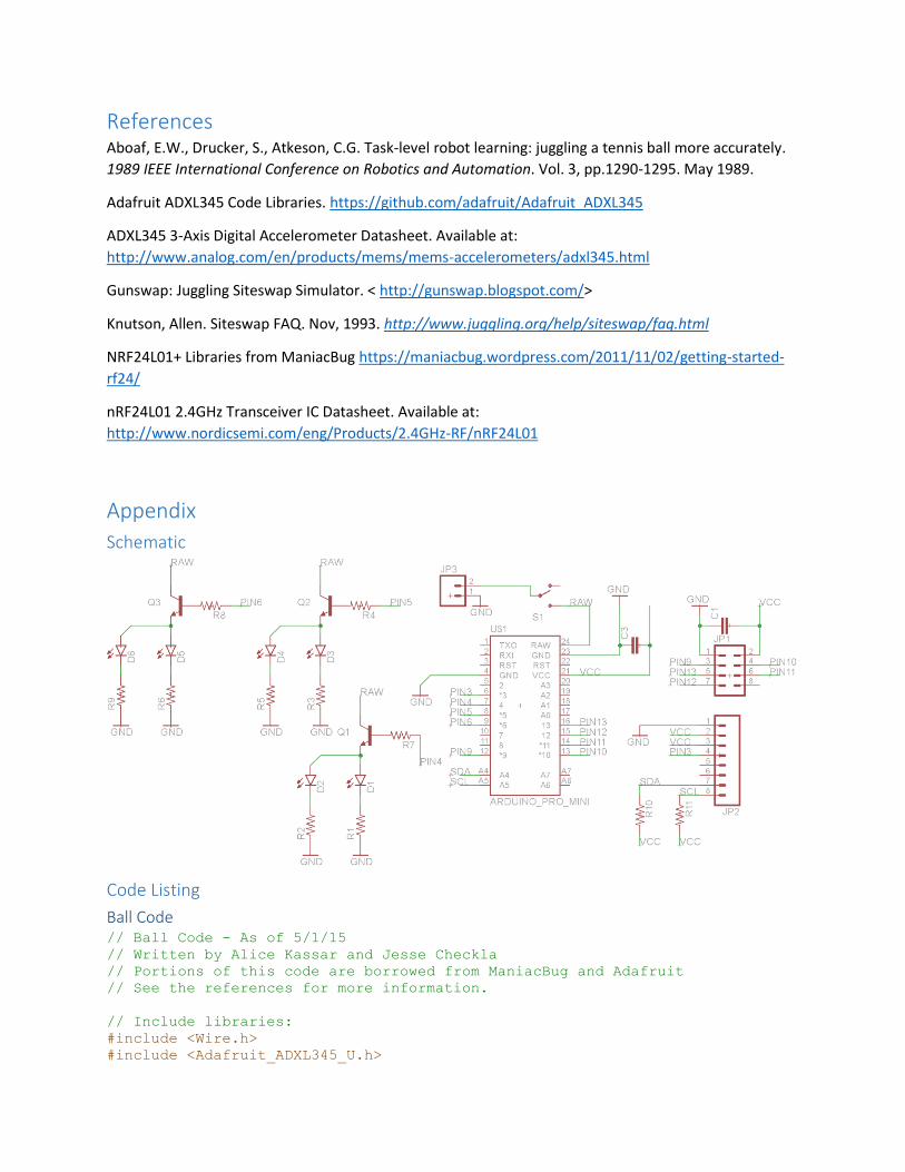
Schematic ............................................................................................................................................... 21
Code Listing ............................................................................................................................................. 21
Ball Code ............................................................................................................................................. 21
Receiver Code ..................................................................................................................................... 26
Method A – Pattern Detection ............................................................................................................ 29
Method B – Pattern Detection ............................................................................................................ 34
User Guide .......................................................................................................................................... 36
Motivation Juggling, as a form of entertainment, has greatly benefited from the development of LED juggling balls.
At present, most balls feature single colors or a standard light-up sequence. Juggling balls with pattern-
dependent color offer a number of advantages. By adding another dimension to the performance, these
balls can increase the entertainment value of a standard routine. Subtle pattern changes can be more
easily recognized by the audience, allowing the performer to incorporate more tricks than they may
have otherwise included. Alternatively, these balls could be used as a practice tool. The color changing
acts as a feedback mechanism, indicating to the juggler whether their pattern was juggled correctly.
Further modes of operation could be imagined and quickly implemented on the same platform.
While other methods of object tracking and recognition exist (e.g. computer vision), it was theorized
that siteswap notation could be used to identify a pattern from discrete events. This numerical notation
is commonly used to describe patterns and to communicate them to other jugglers. Mathematically,
however, siteswap can be used to discover new patterns. These same principles can be used to
empirically identify a juggling pattern by detecting the order in which balls are thrown and caught. This
is the basis for the proposed real-time pattern detection. Included in this report is a brief introduction to
siteswap notation.
Siteswap The following discussion is not a comprehensive guide but rather an introductory lesson to provide the
requisite knowledge needed to understand the notation used throughout the project report.
Siteswap, first invented in 1985, is a useful mathematical notation for representing juggling patterns. In
the most general definition, siteswap is used “to keep track of the order that balls are thrown and
caught” (Knutson, 1993). A string of numbers encodes a specific series of throws and catches. Vanilla
siteswap is the simplest version of this notation and, as a result, it is easy to learn but limited in scope.
Vanilla siteswap, for example, cannot describe a behind-the-back throw. It is also a requirement that
throws alternate hands and only one ball be thrown at a time.
The number assigned to a throw details how many throws occur before that ball is thrown again. More
specifically, a throw is labelled an “N,” if N-1 throws occur before that ball is thrown again. The
sequence of numbers can vary in length, but the notation is simplified to the smallest repeating unit. For
example, the most common 3-ball pattern is simply called “3,” because every ball (N) is thrown again
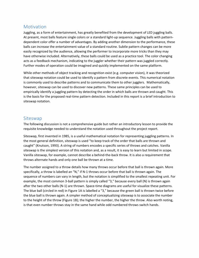
after the two other balls (N-1) are thrown. Space-time diagrams are useful for visualize these patterns.
The blue ball (circled in red) in Figure 1A is labelled a “3,” because the green ball is thrown twice before
the blue ball is thrown again. A simpler method of conceptualizing siteswap is to associate the number
to the height of the throw (Figure 1B); the higher the number, the higher the throw. Also worth noting,
is that even number throws stay in the same hand while odd numbered throws switch hands.
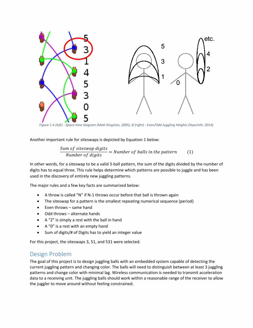
Figure 1 A (left) - Space-time diagram (Matt Kingston, 2005), B (right) - Even/Odd Juggling Heights (Hyacinth, 2014).
Another important rule for siteswaps is depicted by Equation 1 below:
𝑆𝑢𝑚 𝑜𝑓 𝑠𝑖𝑡𝑒𝑠𝑤𝑎𝑝 𝑑𝑖𝑔𝑖𝑡𝑠
𝑁𝑢𝑚𝑏𝑒𝑟 𝑜𝑓 𝑑𝑖𝑔𝑖𝑡𝑠= 𝑁𝑢𝑚𝑏𝑒𝑟 𝑜𝑓 𝑏𝑎𝑙𝑙𝑠 𝑖𝑛 𝑡ℎ𝑒 𝑝𝑎𝑡𝑡𝑒𝑟𝑛 (1)
In other words, for a siteswap to be a valid 3-ball pattern, the sum of the digits divided by the number of
digits has to equal three. This rule helps determine which patterns are possible to juggle and has been
used in the discovery of entirely new juggling patterns.
The major rules and a few key facts are summarized below:
A throw is called “N” if N-1 throws occur before that ball is thrown again
The siteswap for a pattern is the smallest repeating numerical sequence (period)
Even throws – same hand
Odd throws – alternate hands
A “2” is simply a rest with the ball in hand
A “0” is a rest with an empty hand
Sum of digits/# of Digits has to yield an integer value
For this project, the siteswaps 3, 51, and 531 were selected.
Design Problem The goal of this project is to design juggling balls with an embedded system capable of detecting the current juggling pattern and changing color. The balls will need to distinguish between at least 3 juggling patterns and change color with minimal lag. Wireless communication is needed to transmit acceleration data to a receiving unit. The juggling balls should work within a reasonable range of the receiver to allow the juggler to move around without feeling constrained.
To reliably recognize the current pattern and respond to pattern variations a robust pattern detection algorithm is needed.
Physically, the final prototype must fit inside a standard juggling ball and be weight-balanced enough to comfortably juggle. The ball itself must be semi-translucent to allow a visible change in color and of a material that will not impede the RF communication. The casing should also be impact resistant as juggling balls are likely to be dropped.
Originally, it was a requirement that the balls work without an external receiving unit. This requirement was relaxed to simplify the pattern recognition by allowing MATLAB to run the algorithm. Although portability was sacrificed, the speed of recognition was not. Future work could be done to make the system standalone. The final prototype should not be limited to one application. The onboard MCU should be reprogrammable to allow future improvements and alternate features.
Main Design Specifications:
Detection of at least three 3-ball juggling patterns
Fast detection (within two periods of the pattern)
Wireless communication
Less than 2.5” in diameter
Under 0.5lb
Semi-translucent and impact resistant
Alternate Solutions This problem could have been approached a number of ways. Juggling ball trajectories have been
reliably tracked using computer vision (Aboaf, E.W., et al. 1989). This system could likely be modified to
predict the current pattern based on the flight path and order of throws. A vision-based system,
however, would still require an embedded system with wireless communication for changing the ball
color. Computer vision systems are also affected by the ambient lighting and the changing ball color
would present a challenging obstacle.
Juggling patterns are periodic and often have noticeably different rhythms. An audio recording system
might present a feasible method for distinguishing patterns. Again, an embedded system is still required
for color changing. This system would also require very precise juggling and a controllable level of
ambient noise. If a throw is not as high as it should have been, the resulting impact would be heard
earlier than expected, confusing the detection system.
Within the range of solutions utilizing internal accelerometers, there are a number of methods that
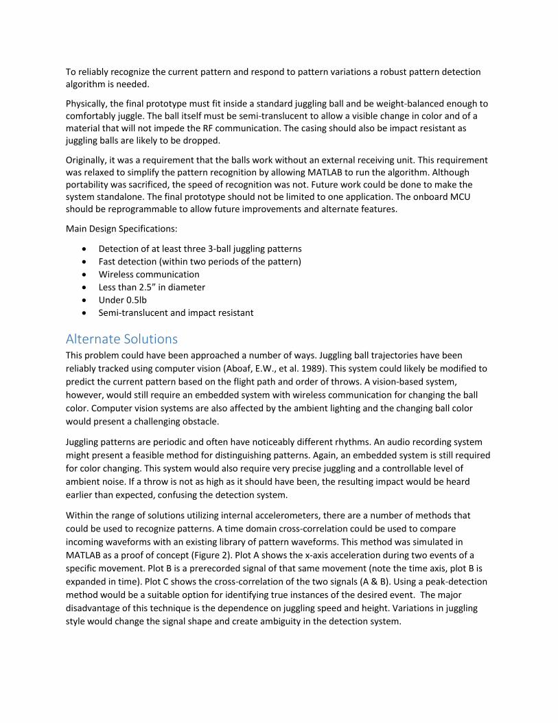
could be used to recognize patterns. A time domain cross-correlation could be used to compare
incoming waveforms with an existing library of pattern waveforms. This method was simulated in
MATLAB as a proof of concept (Figure 2). Plot A shows the x-axis acceleration during two events of a
specific movement. Plot B is a prerecorded signal of that same movement (note the time axis, plot B is
expanded in time). Plot C shows the cross-correlation of the two signals (A & B). Using a peak-detection
method would be a suitable option for identifying true instances of the desired event. The major
disadvantage of this technique is the dependence on juggling speed and height. Variations in juggling
style would change the signal shape and create ambiguity in the detection system.
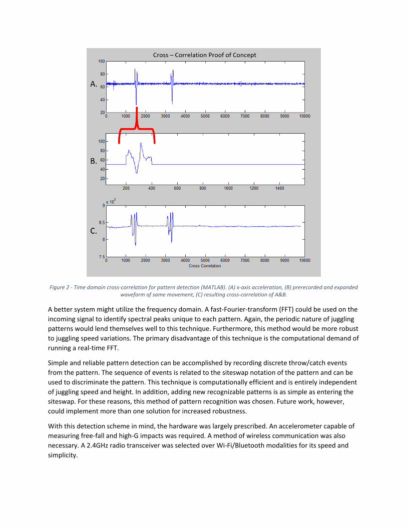
Figure 2 - Time domain cross-correlation for pattern detection (MATLAB). (A) x-axis acceleration, (B) prerecorded and expanded waveform of same movement, (C) resulting cross-correlation of A&B.
A better system might utilize the frequency domain. A fast-Fourier-transform (FFT) could be used on the
incoming signal to identify spectral peaks unique to each pattern. Again, the periodic nature of juggling
patterns would lend themselves well to this technique. Furthermore, this method would be more robust
to juggling speed variations. The primary disadvantage of this technique is the computational demand of
running a real-time FFT.
Simple and reliable pattern detection can be accomplished by recording discrete throw/catch events
from the pattern. The sequence of events is related to the siteswap notation of the pattern and can be
used to discriminate the pattern. This technique is computationally efficient and is entirely independent
of juggling speed and height. In addition, adding new recognizable patterns is as simple as entering the
siteswap. For these reasons, this method of pattern recognition was chosen. Future work, however,
could implement more than one solution for increased robustness.
With this detection scheme in mind, the hardware was largely prescribed. An accelerometer capable of
measuring free-fall and high-G impacts was required. A method of wireless communication was also
necessary. A 2.4GHz radio transceiver was selected over Wi-Fi/Bluetooth modalities for its speed and
simplicity.
Detailed Design Provided in this section is a detailed description of the final design. Major design decisions are discussed
throughout. In addition, obstacles overcome during the debugging process are explained.
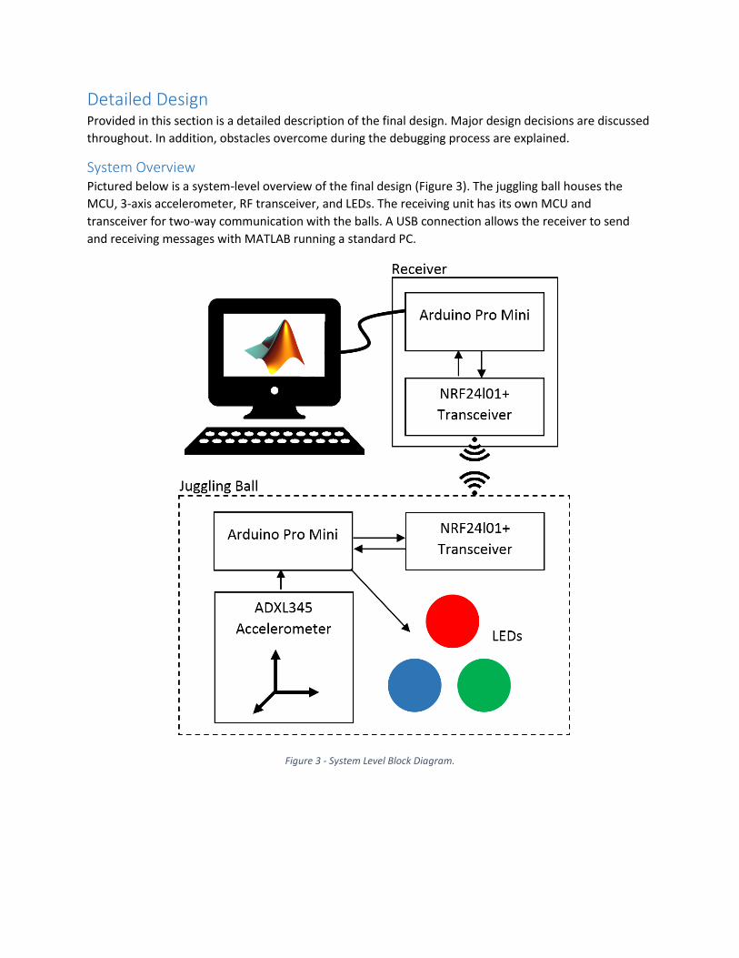
System Overview Pictured below is a system-level overview of the final design (Figure 3). The juggling ball houses the
MCU, 3-axis accelerometer, RF transceiver, and LEDs. The receiving unit has its own MCU and
transceiver for two-way communication with the balls. A USB connection allows the receiver to send
and receiving messages with MATLAB running a standard PC.
Figure 3 - System Level Block Diagram.
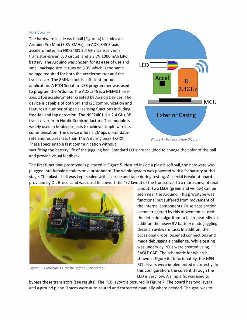
Hardware The hardware inside each ball (Figure 4) includes an
Arduino Pro Mini (3.3V 8MHz), an ADXL345 3-axis
accelerometer, an NRF24l01 2.4 GHz transceiver, a
transistor-driven LED circuit, and a 3.7V 1000mAh LiPo
battery. The Arduino was chosen for its ease of use and
small package size. It runs on 3.3V which is the same
voltage required for both the accelerometer and the
transceiver. The 8MHz clock is sufficient for our
application. A FTDI Serial-to-USB programmer was used
to program the Arduino. The ADXL345 is a MEMS three-
axis, ±16g accelerometer created by Analog Devices. The
device is capable of both SPI and I2C communication and
features a number of special sensing functions including
free-fall and tap detection. The NRF24l01 is a 2.4 GHz RF
transceiver from Nordic Semiconductors. This module is
widely used in hobby projects to achieve simple wireless
communication. The device offers a 2Mbps on-air data-
rate and requires less than 14mA during peak TX/RX.
These specs enable fast communication without
sacrificing the battery life of the juggling ball. Standard LEDs are included to change the color of the ball
and provide visual feedback.
The first functional prototype is pictured in Figure 5. Nestled inside a plastic softball, the hardware was
plugged into female headers on a protoboard. The whole system was powered with a 9v battery at this
stage. The plastic ball was kept sealed with a zip-tie and tape during testing. A special breakout board
provided by Dr. Bruce Land was used to convert the 4x2 layout of the transceiver to a more conventional
pinout. Two LEDs (green and yellow) can be
seen near the Arduino. This prototype was
functional but suffered from movement of
the internal components. False acceleration
events triggered by this movement caused
the detection algorithm to fail repeatedly. In
addition the heavy 9V battery made juggling
these an awkward task. In addition, the
occasional drops loosened connections and
made debugging a challenge. While testing
was underway PCBs were created using
EAGLE CAD. The schematic for which is
shown in Figure 6. Unfortunately, the NPN
BJT drivers were implemented incorrectly. In
this configuration, the current through the
LED is very low. A simple fix was used to
bypass these transistors (see results). The PCB layout is pictured in Figure 7. The board has two layers
and a ground plane. Traces were auto-routed and corrected manually where needed. The goal was to
Figure 4 - Ball Hardware Diagram
Figure 5 - Prototype #1, plastic soft ball, 9V battery.
reduce prototype size and create a circular PCB for easy mounting inside a sphere. The final diameter
was 2.04 inches. The PCBs were arranged in an array and ordered as one board (Figure 8). The circular
PCBs were separated using a bandsaw (Figure 9).
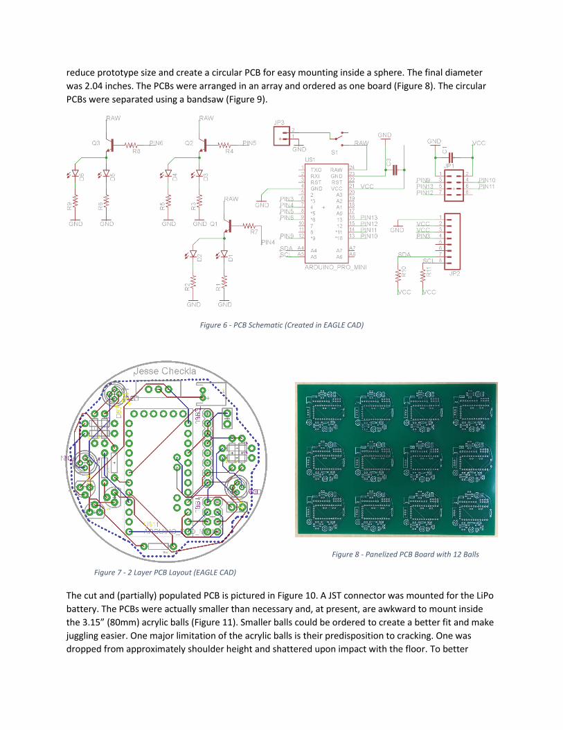
Figure 6 - PCB Schematic (Created in EAGLE CAD)
The cut and (partially) populated PCB is pictured in Figure 10. A JST connector was mounted for the LiPo
battery. The PCBs were actually smaller than necessary and, at present, are awkward to mount inside
the 3.15” (80mm) acrylic balls (Figure 11). Smaller balls could be ordered to create a better fit and make
juggling easier. One major limitation of the acrylic balls is their predisposition to cracking. One was
dropped from approximately shoulder height and shattered upon impact with the floor. To better
Figure 7 - 2 Layer PCB Layout (EAGLE CAD)
Figure 8 - Panelized PCB Board with 12 Balls
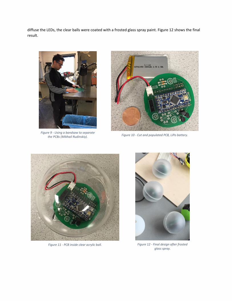
diffuse the LEDs, the clear balls were coated with a frosted glass spray paint. Figure 12 shows the final
result.
Figure 9 - Using a bandsaw to separate the PCBs (Mikhail Rudinskiy). Figure 10 - Cut and populated PCB, LiPo battery.
Figure 11 - PCB inside clear acrylic ball. Figure 12 - Final design after frosted glass spray.
Software
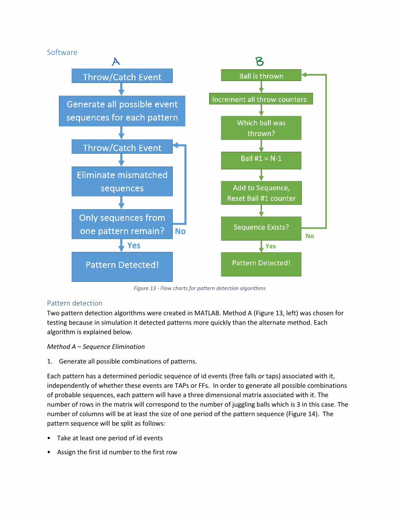
Figure 13 - Flow charts for pattern detection algorithms
Pattern detection Two pattern detection algorithms were created in MATLAB. Method A (Figure 13, left) was chosen for
testing because in simulation it detected patterns more quickly than the alternate method. Each
algorithm is explained below.
Method A – Sequence Elimination
1. Generate all possible combinations of patterns.
Each pattern has a determined periodic sequence of id events (free falls or taps) associated with it,
independently of whether these events are TAPs or FFs. In order to generate all possible combinations
of probable sequences, each pattern will have a three dimensional matrix associated with it. The
number of rows in the matrix will correspond to the number of juggling balls which is 3 in this case. The
number of columns will be at least the size of one period of the pattern sequence (Figure 14). The
pattern sequence will be split as follows:
• Take at least one period of id events
• Assign the first id number to the first row
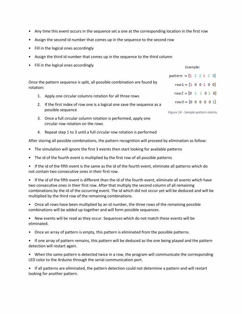
• Any time this event occurs in the sequence set a one at the corresponding location in the first row
• Assign the second id number that comes up in the sequence to the second row
• Fill in the logical ones accordingly
• Assign the third id number that comes up in the sequence to the third column
• Fill in the logical ones accordingly
Once the pattern sequence is split, all possible combination are found by rotation:
1. Apply one circular columns rotation for all three rows
2. If the first index of row one is a logical one save the sequence as a possible sequence
3. Once a full circular column rotation is performed, apply one circular row rotation on the rows
4. Repeat step 1 to 3 until a full circular row rotation is performed
After storing all possible combinations, the pattern recognition will proceed by elimination as follow:
• The simulation will ignore the first 3 events then start looking for available patterns
• The id of the fourth event is multiplied by the first row of all possible patterns
• If the id of the fifth event is the same as the id of the fourth event, eliminate all patterns which do not contain two consecutive ones in their first row.
• If the id of the fifth event is different than the id of the fourth event, eliminate all events which have two consecutive ones in their first row. After that multiply the second column of all remaining combinations by the id of the occurring event. The id which did not occur yet will be deduced and will be multiplied by the third row of the remaining combinations.
• Once all rows have been multiplied by an id number, the three rows of the remaining possible combinations will be added up together and will form possible sequences.
• New events will be read as they occur. Sequences which do not match these events will be eliminated.
• Once an array of pattern is empty, this pattern is eliminated from the possible patterns.
• If one array of pattern remains, this pattern will be deduced as the one being played and the pattern detection will restart again.
• When the same pattern is detected twice in a row, the program will communicate the corresponding LED color to the Arduino through the serial communication port.
• If all patterns are eliminated, the pattern detection could not determine a pattern and will restart looking for another pattern.
Figure 14 - Sample pattern matrix.
The pattern recognition algorithm has a hold variable which stores the last pattern detected. Once a new pattern has been recognized, the algorithm will save it stored in the hold variable. A change in pattern will not be deduced unless the algorithm recognizes the same pattern twice. An undetected pattern will not affect the hold variable. It results usually from a loss of Tap or Free Fall events. Loss of data might results in detecting false patterns. For example, if pattern 2 is recognized when pattern 1 is being played, the hold variable will be updated and the program will wait until pattern 2 is recognized again before changing the ball’s color. However, it is very unlikely for the same false sequence to occur twice in a row. Therefore, it is very improbable to settle for a false pattern and change the color accordingly. As a result the hold variable reduces the risk of switching to a false pattern in case some events are being dropped.
The method explained above requires around three to four events to determine the juggling pattern. One drawback is that the method can determine an incorrect sequence but cannot correct it.
Method B – Throw Counter
The second method (Figure 13, right) utilizes the fundamental rule of siteswap; namely, a throw is called N if N-1 throws occur before it is thrown again. A throw counter is initialized for each ball. When a throw event is received, the throw counter for each ball is incremented. However, for the ball that was thrown, the previous value of the throw counter is stored in an array. The throw counter for this ball is then reset. The previous value of the throw counter is the siteswap of the previous throw. The array for each ball is created and a sequence is concatenated from these arrays. The sequence is compared to a lookup table for existing patterns. If the growing sequence matches an entry in the lookup table, the algorithm was successful in identifying the pattern.
At present, prior knowledge of the length of the siteswap is required. For example, if the current pattern is 531, the lookup table has items 531, 315, and 135. The algorithm uses the most recent three values in the sequence to search the lookup table. This method would require better generalization to make it applicable to a wide-range of siteswaps. For example, the algorithm might mistakenly detect the pattern “51” inside the longer siteswap “4515141.”
Much like the first algorithm, a pattern needs to be detected twice in order to qualify as a detection. This prevents failed readings from false or missing throws (though it does not solve the “51” dilemma mentioned above). The major benefit of Method B is that the fall-detection of the accelerometer is inherently more reliable than tap-detection. The way in which a ball is caught can drastically impact the perceived acceleration, however, a throw is a zero-g event no matter how it is thrown. The downside to this algorithm is that it requires 3 to 4 throws whereas the alternate method needs 3 to 4 events (throws OR catches). Therefore, algorithm B is slower to detect.
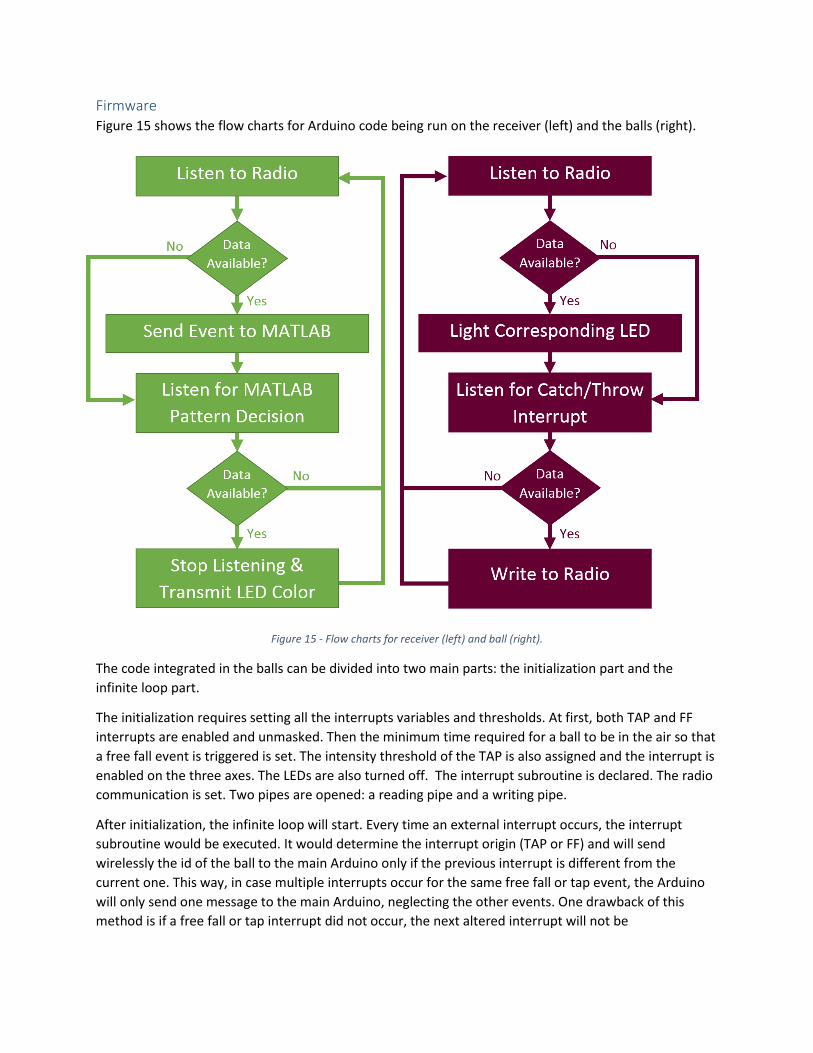
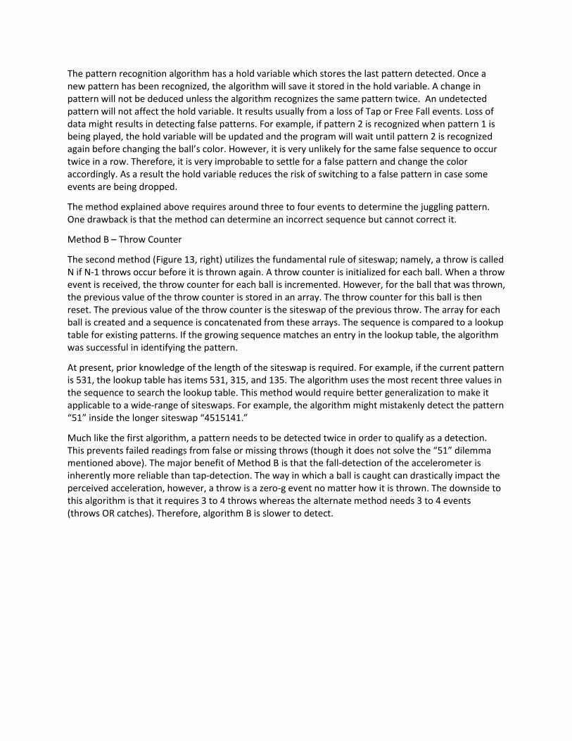
Firmware Figure 15 shows the flow charts for Arduino code being run on the receiver (left) and the balls (right).
Figure 15 - Flow charts for receiver (left) and ball (right).
The code integrated in the balls can be divided into two main parts: the initialization part and the
infinite loop part.
The initialization requires setting all the interrupts variables and thresholds. At first, both TAP and FF
interrupts are enabled and unmasked. Then the minimum time required for a ball to be in the air so that
a free fall event is triggered is set. The intensity threshold of the TAP is also assigned and the interrupt is
enabled on the three axes. The LEDs are also turned off. The interrupt subroutine is declared. The radio
communication is set. Two pipes are opened: a reading pipe and a writing pipe.
After initialization, the infinite loop will start. Every time an external interrupt occurs, the interrupt
subroutine would be executed. It would determine the interrupt origin (TAP or FF) and will send
wirelessly the id of the ball to the main Arduino only if the previous interrupt is different from the
current one. This way, in case multiple interrupts occur for the same free fall or tap event, the Arduino
will only send one message to the main Arduino, neglecting the other events. One drawback of this
method is if a free fall or tap interrupt did not occur, the next altered interrupt will not be
communicated to the receiver. The loop will also listen to check if a broadcast message is being
delivered by the main Arduino. If so, it will light up the corresponding LED.
The receiver code is responsible for listening to incoming radio transmissions, communication with
MATLAB, and sending out commands to change ball color. Similar to the ball code initialization, the
radio is setup by creating a reading and writing pipe. The radio listens for incoming throw/catch events.
When an event is detected it is printed to the serial port. Both the ball ID number and type of event are
sent to MATLAB. While no event is detected, the receiver awaits a decision from MATLAB. If a pattern is
recognized, the Arduino reads the serial port, stops listening for new events, and transmits a message to
change ball color. The receiver immediately continues listening for incoming events.
Testing Testing the pattern detection algorithms simply required entering the necessary event stream and
confirming that the appropriate pattern was selected. The number of events required for detection was
also deduced from the testing stage.
The hardware and firmware testing was performed in stages during the building process. We first
experimented with the ADXL345 TAP/FF detection on a breadboard. Once the wireless communication
was implemented, we again tested and calibrated these thresholds. The wireless communication testing
was limited to checking for packet loss.
When prototype #1 (Figure 5) was assembled, we triggered the interrupts (tapping, free-fall) and
compared the event stream with the predicted outcome. When the throws and catches were being
correctly identified, we moved into full juggling pattern detection. Again, a known pattern was juggled
and compared to the recorded events. The on-board LEDs were used to confirm that messages from the
PC-attached unit were reaching the balls.
Upon arrival, the PCBs were tested for proper connection with a multimeter. After soldering the
components and mounting the PCBs in the acrylic shells, the final prototype was tested with the same
guidelines as prototype #1.
Results In early stage testing, determining suitable thresholds for the ADXL345 accelerometer was the biggest
obstacle because the attached communication wire made achieving true free-fall a difficult task. In
addition, repeatedly throwing and “tapping” the breadboard resulted in a lot of falsely triggered
interrupts. It was evident that implementing the wireless communication and soldering the prototype
was necessary to get more reliable data.
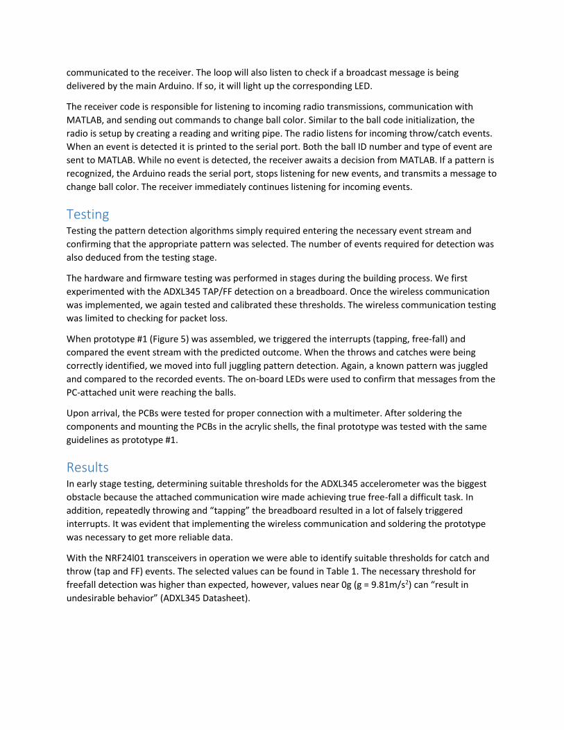
With the NRF24l01 transceivers in operation we were able to identify suitable thresholds for catch and
throw (tap and FF) events. The selected values can be found in Table 1. The necessary threshold for
freefall detection was higher than expected, however, values near 0g (g = 9.81m/s2) can “result in
undesirable behavior” (ADXL345 Datasheet).
When testing the wireless communication we noticed some anticipated events were missing at the
receiver. It was unclear whether this was due to interference (RF collision) or if the accelerometer had
missed an event. We investigated the carrier detect (CD) feature of the NRF24l01 and wrote the
necessary code but ultimately discovered that it was unnecessary. When we attempted to trigger two
simultaneous events we always received both. Moreover, the balls should not be thrown or caught
simultaneously during the juggling siteswap patterns implemented in our design.
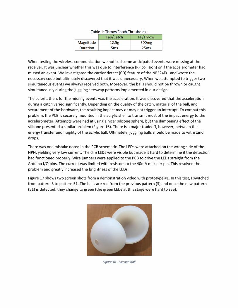
The culprit, then, for the missing events was the acceleration. It was discovered that the acceleration
during a catch varied significantly. Depending on the quality of the catch, material of the ball, and
securement of the hardware, the resulting impact may or may not trigger an interrupt. To combat this
problem, the PCB is securely mounted in the acrylic shell to transmit most of the impact energy to the
accelerometer. Attempts were had at using a nicer silicone sphere, but the dampening effect of the
silicone presented a similar problem (Figure 16). There is a major tradeoff, however, between the
energy transfer and fragility of the acrylic ball. Ultimately, juggling balls should be made to withstand
drops.
There was one mistake noted in the PCB schematic. The LEDs were attached on the wrong side of the
NPN, yielding very low current. The dim LEDs were visible but made it hard to determine if the detection
had functioned properly. Wire jumpers were applied to the PCB to drive the LEDs straight from the
Arduino I/O pins. The current was limited with resistors to the 40mA max per pin. This resolved the
problem and greatly increased the brightness of the LEDs.
Figure 17 shows two screen shots from a demonstration video with prototype #1. In this test, I switched
from pattern 3 to pattern 51. The balls are red from the previous pattern (3) and once the new pattern
(51) is detected, they change to green (the green LEDs at this stage were hard to see).
Figure 16 - Silicone Ball
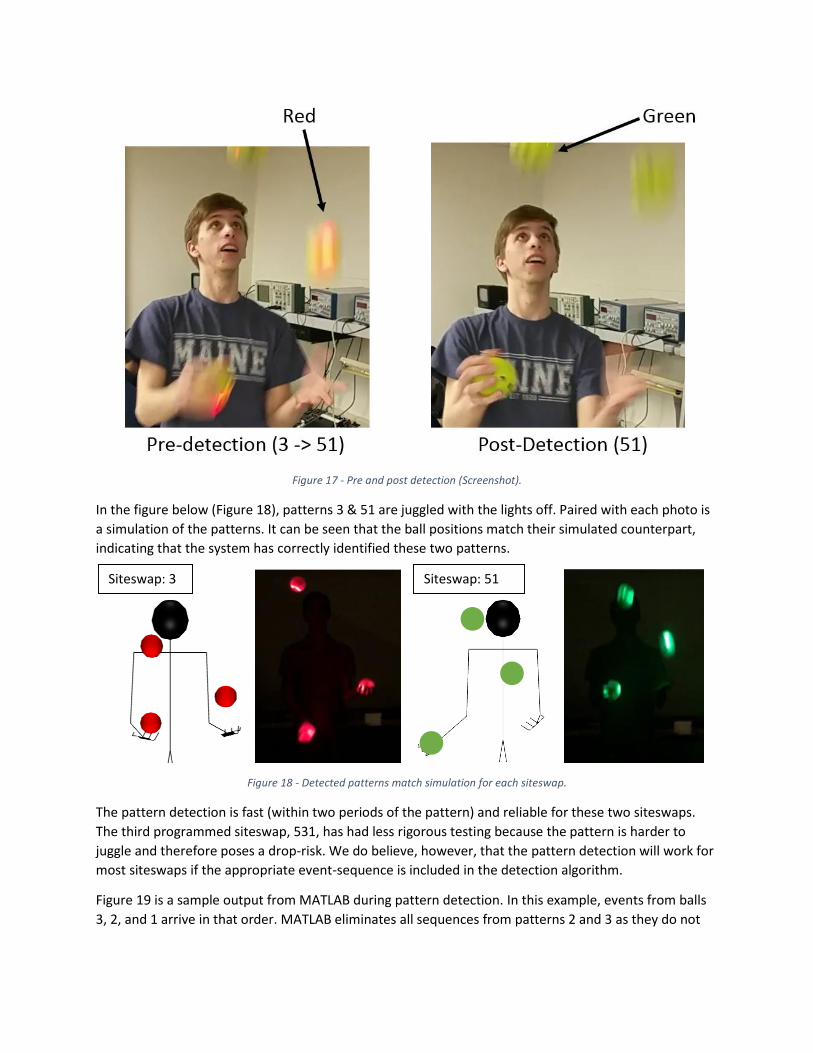
Figure 17 - Pre and post detection (Screenshot).
In the figure below (Figure 18), patterns 3 & 51 are juggled with the lights off. Paired with each photo is
a simulation of the patterns. It can be seen that the ball positions match their simulated counterpart,
indicating that the system has correctly identified these two patterns.
Figure 18 - Detected patterns match simulation for each siteswap.
The pattern detection is fast (within two periods of the pattern) and reliable for these two siteswaps.
The third programmed siteswap, 531, has had less rigorous testing because the pattern is harder to
juggle and therefore poses a drop-risk. We do believe, however, that the pattern detection will work for
most siteswaps if the appropriate event-sequence is included in the detection algorithm.
Figure 19 is a sample output from MATLAB during pattern detection. In this example, events from balls
3, 2, and 1 arrive in that order. MATLAB eliminates all sequences from patterns 2 and 3 as they do not
Siteswap: 3 Siteswap: 51
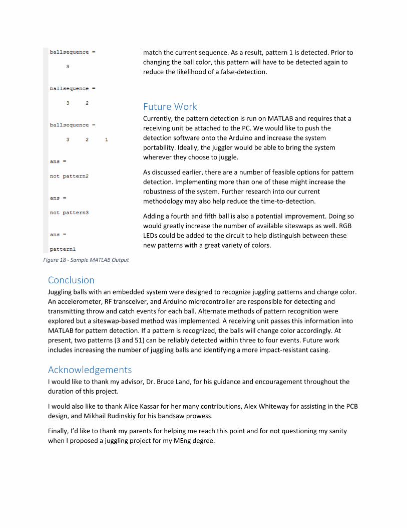
match the current sequence. As a result, pattern 1 is detected. Prior to
changing the ball color, this pattern will have to be detected again to
reduce the likelihood of a false-detection.
Future Work Currently, the pattern detection is run on MATLAB and requires that a
receiving unit be attached to the PC. We would like to push the
detection software onto the Arduino and increase the system
portability. Ideally, the juggler would be able to bring the system
wherever they choose to juggle.
As discussed earlier, there are a number of feasible options for pattern
detection. Implementing more than one of these might increase the
robustness of the system. Further research into our current
methodology may also help reduce the time-to-detection.
Adding a fourth and fifth ball is also a potential improvement. Doing so
would greatly increase the number of available siteswaps as well. RGB
LEDs could be added to the circuit to help distinguish between these
new patterns with a great variety of colors.
Conclusion Juggling balls with an embedded system were designed to recognize juggling patterns and change color.
An accelerometer, RF transceiver, and Arduino microcontroller are responsible for detecting and
transmitting throw and catch events for each ball. Alternate methods of pattern recognition were
explored but a siteswap-based method was implemented. A receiving unit passes this information into
MATLAB for pattern detection. If a pattern is recognized, the balls will change color accordingly. At
present, two patterns (3 and 51) can be reliably detected within three to four events. Future work
includes increasing the number of juggling balls and identifying a more impact-resistant casing.
Acknowledgements I would like to thank my advisor, Dr. Bruce Land, for his guidance and encouragement throughout the
duration of this project.
I would also like to thank Alice Kassar for her many contributions, Alex Whiteway for assisting in the PCB
design, and Mikhail Rudinskiy for his bandsaw prowess.
Finally, I’d like to thank my parents for helping me reach this point and for not questioning my sanity
when I proposed a juggling project for my MEng degree.
Figure 18 - Sample MATLAB Output
References Aboaf, E.W., Drucker, S., Atkeson, C.G. Task-level robot learning: juggling a tennis ball more accurately.
1989 IEEE International Conference on Robotics and Automation. Vol. 3, pp.1290-1295. May 1989.
Adafruit ADXL345 Code Libraries. https://github.com/adafruit/Adafruit_ADXL345
ADXL345 3-Axis Digital Accelerometer Datasheet. Available at:
http://www.analog.com/en/products/mems/mems-accelerometers/adxl345.html
Gunswap: Juggling Siteswap Simulator. < http://gunswap.blogspot.com/>
Knutson, Allen. Siteswap FAQ. Nov, 1993. http://www.juggling.org/help/siteswap/faq.html
NRF24L01+ Libraries from ManiacBug https://maniacbug.wordpress.com/2011/11/02/getting-started-
rf24/
nRF24L01 2.4GHz Transceiver IC Datasheet. Available at:
http://www.nordicsemi.com/eng/Products/2.4GHz-RF/nRF24L01
Appendix
Schematic
Code Listing
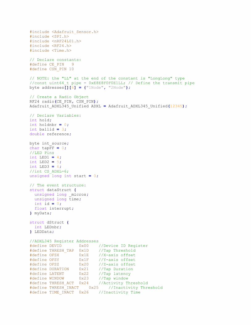
Ball Code // Ball Code - As of 5/1/15
// Written by Alice Kassar and Jesse Checkla
// Portions of this code are borrowed from ManiacBug and Adafruit
// See the references for more information.
// Include libraries:
#include <Wire.h>
#include <Adafruit_ADXL345_U.h>
#include <Adafruit_Sensor.h>
#include <SPI.h>
#include <nRF24L01.h>
#include <RF24.h>
#include <Time.h>
// Declare constants:
#define CE_PIN 9
#define CSN_PIN 10
// NOTE: the "LL" at the end of the constant is "LongLong" type
//const uint64_t pipe = 0xE8E8F0F0E1LL; // Define the transmit pipe
byte addresses[][6] = {"1Node", "2Node"};
// Create a Radio Object
RF24 radio(CE_PIN, CSN_PIN);
Adafruit_ADXL345_Unified ADXL = Adafruit_ADXL345_Unified(12345);
// Declare Variables:
int hold;
int holdnbr = 0;
int ballid = 3;
double reference;
byte int_source;
char tapFF = 0;
//LED Pins
int LED1 = 4;
int LED2 = 5;
int LED3 = 6;
//int CS_ADXL=6;
unsigned long int start = 0;
// The event structure:
struct dataStruct {
unsigned long _micros;
unsigned long time;
int id = 0;
float interrupt;
} myData;
struct dStruct {
int LEDnbr;
} LEDData;
//ADXL345 Register Addresses
#define DEVID 0x00 //Device ID Register
#define THRESH_TAP 0x1D //Tap Threshold
#define OFSX 0x1E //X-axis offset
#define OFSY 0x1F //Y-axis offset
#define OFSZ 0x20 //Z-axis offset
#define DURATION 0x21 //Tap Duration
#define LATENT 0x22 //Tap latency
#define WINDOW 0x23 //Tap window
#define THRESH_ACT 0x24 //Activity Threshold
#define THRESH_INACT 0x25 //Inactivity Threshold
#define TIME_INACT 0x26 //Inactivity Time
#define ACT_INACT_CTL 0x27 //Axis enable control for activity and
inactivity detection
#define THRESH_FF 0x28 //free-fall threshold
#define TIME_FF 0x29 //Free-Fall Time
#define TAP_AXES 0x2A //Axis control for tap/double tap
#define ACT_TAP_STATUS 0x2B //Source of tap/double tap
#define BW_RATE 0x2C //Data rate and power mode control
#define POWER_CTL 0x2D //Power Control Register
#define INT_ENABLE 0x2E //Interrupt Enable Control
#define INT_MAP 0x2F //Interrupt Mapping Control
#define INT_SOURCE 0x30 //Source of interrupts
#define DATA_FORMAT 0x31 //Data format control
#define DATAX0 0x32 //X-Axis Data 0
#define DATAX1 0x33 //X-Axis Data 1
#define DATAY0 0x34 //Y-Axis Data 0
#define DATAY1 0x35 //Y-Axis Data 1
#define DATAZ0 0x36 //Z-Axis Data 0
#define DATAZ1 0x37 //Z-Axis Data 1
#define FIFO_CTL 0x38 //FIFO control
#define FIFO_STATUS 0x39 //FIFO status
void setup()
{
// Initialize the I2C
Wire.begin();
// Open Serial Communication:
Serial.begin(9600);
// Initialize the accelerometer registers/thresholds
ADXL.writeRegister(ADXL345_REG_THRESH_TAP, 0b11001000);
ADXL.writeRegister(ADXL345_REG_DUR, 0x08);
ADXL.writeRegister(ADXL345_REG_LATENT, 0x00);
ADXL.writeRegister(ADXL345_REG_WINDOW, 0x00);
ADXL.writeRegister(ADXL345_REG_TAP_AXES, 0b00000111);
ADXL.writeRegister(ADXL345_REG_POWER_CTL, 0x08);
ADXL.writeRegister(ADXL345_REG_INT_MAP, 0b10111011);
ADXL.writeRegister(ADXL345_REG_DATA_FORMAT, 0x01);
ADXL.writeRegister(ADXL345_REG_INT_ENABLE, 0b11000100);
ADXL.writeRegister(ADXL345_REG_THRESH_FF, 0x05);
ADXL.writeRegister(ADXL345_REG_TIME_FF, 0x05);
//Set LED Pins as Output
pinMode(LED1, OUTPUT);
pinMode(LED2, OUTPUT);
pinMode(LED3, OUTPUT);
// pinMode(CS_ADXL, OUTPUT);
//digitalWrite(CS_ADXL, HIGH);
// Set LEDs LOW
digitalWrite(LED1, LOW);
digitalWrite(LED2, LOW);
digitalWrite(LED3, LOW);
delay(10);
//Initialize the interrupts
int_source = ADXL.readRegister(ADXL345_REG_INT_SOURCE);
attachInterrupt(1, TapFFinterrupt, RISING);
//Start Radio Communication
radio.begin();
// Set the PA Level low to prevent power supply related issues since this
is a
// getting_started sketch, and the likelihood of close proximity of the
devices. RF24_PA_MAX is default.
radio.setPALevel(RF24_PA_LOW);
radio.openWritingPipe(addresses[1]);
radio.openReadingPipe(1, addresses[0]);
radio.startListening();
// Wait for starting seed:
while (start == 0)
{
radio.read( &myData, sizeof(myData));
start = myData._micros;
}
myData.id = ballid;
radio.stopListening();
// Event timer (no longer in use, JC).
reference = millis();
}
void loop()
{
if (int_source == 255)
{
int_source = ADXL.readRegister( ADXL345_REG_INT_SOURCE );
}
if (tapFF == 1)
{
int_source = ADXL.readRegister( ADXL345_REG_INT_SOURCE );
tapFF = 0;
if (int_source == 195)
{
myData.interrupt = 1;
ADXL.writeRegister(ADXL345_REG_INT_ENABLE, 0b11000100);
}
else if (int_source == 135)
{
myData.interrupt = 2;
ADXL.writeRegister(ADXL345_REG_INT_ENABLE, 0b11000000);
}
else myData.interrupt = 3;
myData._micros = micros();
if (int_source != holdnbr && myData.interrupt != 3)
{
radio.write(&myData, sizeof(myData));
}
if (myData.interrupt != 3)
holdnbr = int_source;
}
radio.startListening();
unsigned long started_waiting_at = micros();
boolean timeout = false;
// While nothing is received
while ( ! radio.available() )
{
// Timeout after 500ms, exit while loop
if (micros() - started_waiting_at > 10 )
{
timeout = true;
break;
}
}
if (timeout)
{
Serial.println(F("No msg from receiver."));
}
else
{
radio.read( &LEDData, sizeof(LEDData));
if (LEDData.LEDnbr == 10)
{
digitalWrite(LED1, LOW);
digitalWrite(LED2, LOW);
// digitalWrite(LED3, LOW);
}
else if (LEDData.LEDnbr == 1)
{
digitalWrite(LED1, HIGH);
digitalWrite(LED2, LOW);
digitalWrite(LED3, LOW);
}
else if (LEDData.LEDnbr == 2)
{
digitalWrite(LED1, LOW);
digitalWrite(LED2, HIGH);
digitalWrite(LED3, LOW);
}
else if (LEDData.LEDnbr == 3)
{
digitalWrite(LED1, LOW);
digitalWrite(LED2, LOW);
digitalWrite(LED3, HIGH);
}
}
radio.stopListening();
} // End Loop
// ISR
void TapFFinterrupt()
{
myData.time = millis() - reference;
tapFF = 1;
}
Receiver Code // Receiver Code - As of 5/1/15
// Written by Jesse Checkla and Alice Kassar
// Portions of this code are borrowed from ManiacBug and Adafruit
// Import Libraries:
#include <SPI.h>
#include <nRF24L01.h>
#include <RF24.h>
#include <SD.h>
#include <QueueArray.h>
// Declare Variables:
#define CE_PIN 9
#define CSN_PIN 10
struct dataStruct {
volatile unsigned long _micros = 1;
volatile unsigned long time;
volatile int id = 0;
volatile float interrupt;
};
dataStruct myData;
dataStruct rData ;
QueueArray <dataStruct> queue;
struct dStruct {
int LEDnbr;
} LEDData;
//File myFile;
float reference;
float timeellapsed;
int counter = 0;
char pattern;
// NOTE: the "LL" at the end of the constant is "LongLong" type
//const uint64_t pipe = 0xE8E8F0F0E1LL; // Define the transmit pipe
byte addresses[][6] = {"1Node", "2Node"};
// Create a Radio Object
RF24 radio(CE_PIN, CSN_PIN);
//timer 0 compare ISR
ISR (TIMER0_COMPA_vect)
{
//Serial.println("interrput ");
if (radio.available() )
{
radio.read( &rData, sizeof(rData) );
if (rData.interrupt == 2 || rData.interrupt == 1)
{
queue.push (rData);
// Serial.println(rData.interrupt);
}
//Decrement the three times if they are not already zero
}
}
void setup()
{
// Start Serial:
Serial.begin(9600);
delay(1000);
// Start Radio Communication
radio.begin();
// Serial.println("Nrf24L01 Receiver Starting");
// Set the PA Level low to prevent power supply related issues since this
is a
// getting_started sketch, and the likelihood of close proximity of the
devices. RF24_PA_MAX is default.
radio.setPALevel(RF24_PA_LOW);
radio.openWritingPipe(addresses[0]);
radio.openReadingPipe(1, addresses[1]);
// Send Starting Seed
radio.write(&myData, sizeof(myData) );
LEDData.LEDnbr = 10;
delay(1);
radio.write(&LEDData, sizeof(LEDData) );
Serial.println("sending seed");
radio.startListening();
reference = millis();
delay(100);
//turn on timer 0 cmp match ISR
TIMSK0 = (1 << OCIE0A);
//set the compare reg to 20 time ticks
OCR0A = 100;
//set prescalar to divide by 1024
TCCR0B = 5;
// turn on clear-on-match
TCCR0A = (1 << WGM01) ;
sei();
}
void loop()
{
if (!queue.isEmpty ())
{
myData = queue.dequeue();
if (myData.interrupt == 1)
{
Serial.println(myData.id);
// Serial.print(" ");
// Serial.print("TAP ");
// Serial.println(myData.time);
}
else if (myData.interrupt == 2)
{
Serial.println(myData.id);
// Serial.print(" ");
// Serial.print("FF ");
// Serial.println(myData.time);
}
}
// Read pattern from MATLAB
pattern = Serial.read();
if (pattern == 'a')
{
TIMSK0 = (0 << OCIE0A);
radio.stopListening();
LEDData.LEDnbr = 1;
radio.write(&LEDData, sizeof(LEDData) );
radio.startListening();
counter = 0;
TIMSK0 = (1 << OCIE0A);
}
else if (pattern == 'b')
{
TIMSK0 = (0 << OCIE0A);
radio.stopListening();
LEDData.LEDnbr = 2;
radio.write(&LEDData, sizeof(LEDData) );
radio.startListening();
counter = 0;
TIMSK0 = (1 << OCIE0A);
}
else if (pattern == 'c')
{
TIMSK0 = (0 << OCIE0A);
radio.stopListening();
LEDData.LEDnbr = 3;
radio.write(&LEDData, sizeof(LEDData) );
radio.startListening();
counter = 0;
TIMSK0 = (1 << OCIE0A);
}
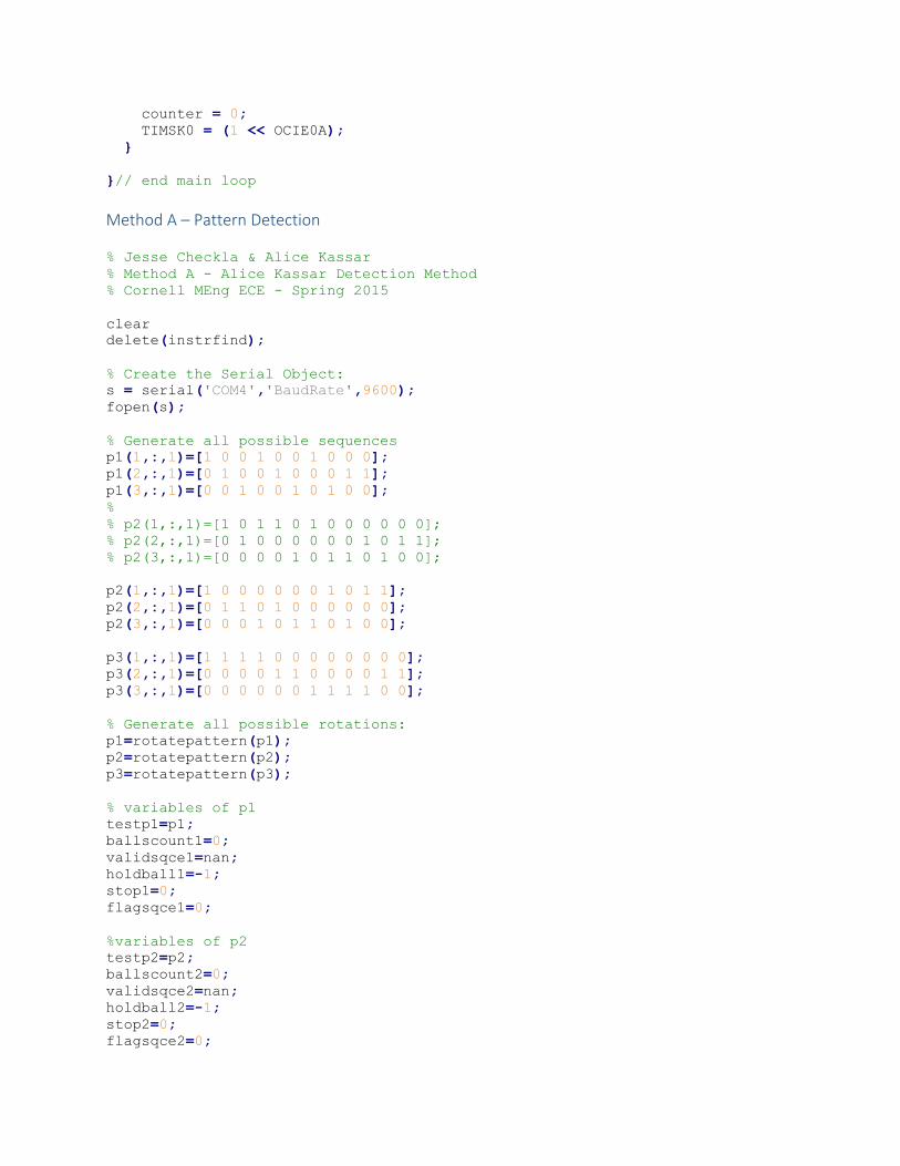
}// end main loop
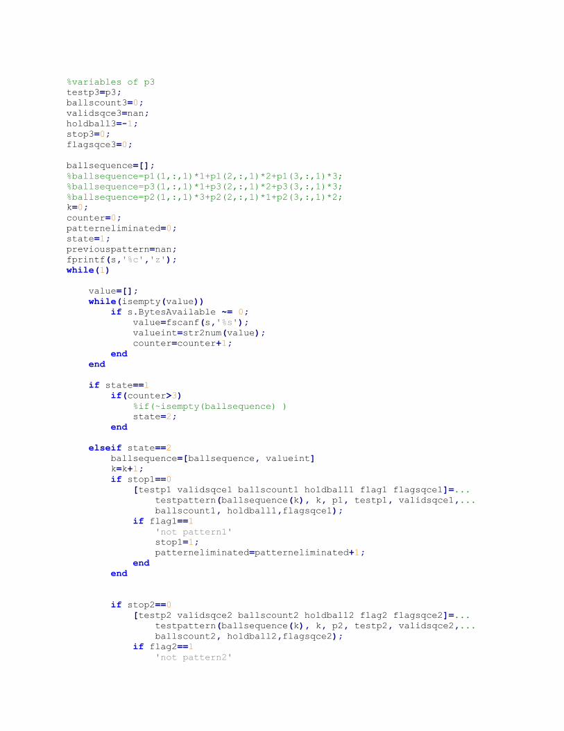
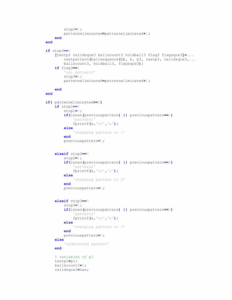
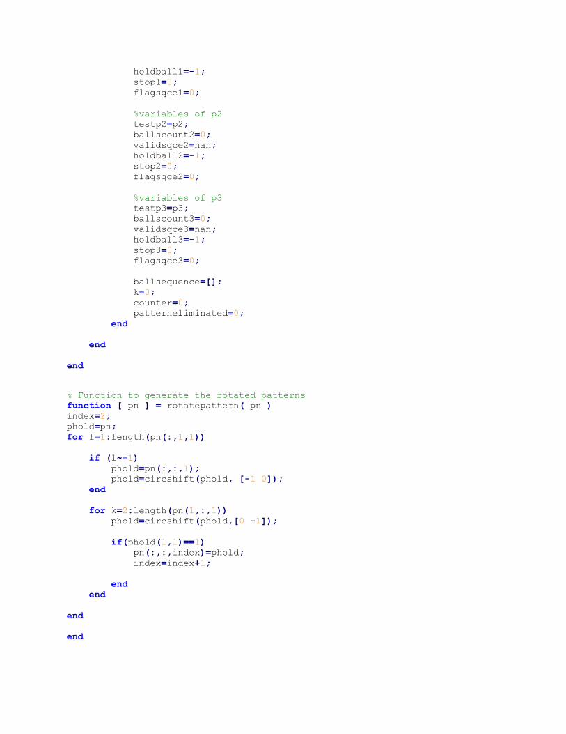
Method A – Pattern Detection
% Jesse Checkla & Alice Kassar
% Method A - Alice Kassar Detection Method
% Cornell MEng ECE - Spring 2015
clear
delete(instrfind);
% Create the Serial Object:
s = serial('COM4','BaudRate',9600);
fopen(s);
% Generate all possible sequences
p1(1,:,1)=[1 0 0 1 0 0 1 0 0 0];
p1(2,:,1)=[0 1 0 0 1 0 0 0 1 1];
p1(3,:,1)=[0 0 1 0 0 1 0 1 0 0];
%
% p2(1,:,1)=[1 0 1 1 0 1 0 0 0 0 0 0];
% p2(2,:,1)=[0 1 0 0 0 0 0 0 1 0 1 1];
% p2(3,:,1)=[0 0 0 0 1 0 1 1 0 1 0 0];
p2(1,:,1)=[1 0 0 0 0 0 0 1 0 1 1];
p2(2,:,1)=[0 1 1 0 1 0 0 0 0 0 0];
p2(3,:,1)=[0 0 0 1 0 1 1 0 1 0 0];
p3(1,:,1)=[1 1 1 1 0 0 0 0 0 0 0 0];
p3(2,:,1)=[0 0 0 0 1 1 0 0 0 0 1 1];
p3(3,:,1)=[0 0 0 0 0 0 1 1 1 1 0 0];
% Generate all possible rotations:
p1=rotatepattern(p1);
p2=rotatepattern(p2);
p3=rotatepattern(p3);
% variables of p1
testp1=p1;
ballscount1=0;
validsqce1=nan;
holdball1=-1;
stop1=0;
flagsqce1=0;
%variables of p2
testp2=p2;
ballscount2=0;
validsqce2=nan;
holdball2=-1;
stop2=0;
flagsqce2=0;
%variables of p3
testp3=p3;
ballscount3=0;
validsqce3=nan;
holdball3=-1;
stop3=0;
flagsqce3=0;
ballsequence=[];
%ballsequence=p1(1,:,1)*1+p1(2,:,1)*2+p1(3,:,1)*3;
%ballsequence=p3(1,:,1)*1+p3(2,:,1)*2+p3(3,:,1)*3;
%ballsequence=p2(1,:,1)*3+p2(2,:,1)*1+p2(3,:,1)*2;
k=0;
counter=0;
patterneliminated=0;
state=1;
previouspattern=nan;
fprintf(s,'%c','z');
while(1)
value=[];
while(isempty(value))
if s.BytesAvailable ~= 0;
value=fscanf(s,'%s');
valueint=str2num(value);
counter=counter+1;
end
end
if state==1
if(counter>3)
%if(~isempty(ballsequence) )
state=2;
end
elseif state==2
ballsequence=[ballsequence, valueint]
k=k+1;
if stop1==0
[testp1 validsqce1 ballscount1 holdball1 flag1 flagsqce1]=...
testpattern(ballsequence(k), k, p1, testp1, validsqce1,...
ballscount1, holdball1,flagsqce1);
if flag1==1
'not pattern1'
stop1=1;
patterneliminated=patterneliminated+1;
end
end
if stop2==0
[testp2 validsqce2 ballscount2 holdball2 flag2 flagsqce2]=...
testpattern(ballsequence(k), k, p2, testp2, validsqce2,...
ballscount2, holdball2,flagsqce2);
if flag2==1
'not pattern2'
stop2=1;
patterneliminated=patterneliminated+1;
end
end
if stop3==0
[testp3 validsqce3 ballscount3 holdball3 flag3 flagsqce3]=...
testpattern(ballsequence(k), k, p3, testp3, validsqce3,...
ballscount3, holdball3, flagsqce3);
if flag3==1
'not pattern3'
stop3=1;
patterneliminated=patterneliminated+1;
end
end
if( patterneliminated>=2)
if stop1==0
stop1=1;
if(isnan(previouspattern) || previouspattern==1)
'pattern1'
fprintf(s,'%c','a');
else
'changing pattern to 1'
end
previouspattern=1;
elseif stop2==0
stop2=1;
if(isnan(previouspattern) || previouspattern==2)
'pattern2'
fprintf(s,'%c','c');
else
'changing pattern to 2'
end
previouspattern=2;
elseif stop3==0
stop3=1;
if(isnan(previouspattern) || previouspattern==3)
'pattern3'
fprintf(s,'%c','b');
else
'changing pattern to 3'
end
previouspattern=3;
else
'undetected pattern'
end
% variables of p1
testp1=p1;
ballscount1=0;
validsqce1=nan;
holdball1=-1;
stop1=0;
flagsqce1=0;
%variables of p2
testp2=p2;
ballscount2=0;
validsqce2=nan;
holdball2=-1;
stop2=0;
flagsqce2=0;
%variables of p3
testp3=p3;
ballscount3=0;
validsqce3=nan;
holdball3=-1;
stop3=0;
flagsqce3=0;
ballsequence=[];
k=0;
counter=0;
patterneliminated=0;
end
end
end
% Function to generate the rotated patterns
function [ pn ] = rotatepattern( pn )
index=2;
phold=pn;
for l=1:length(pn(:,1,1))
if (l~=1)
phold=pn(:,:,1);
phold=circshift(phold, [-1 0]);
end
for k=2:length(pn(1,:,1))
phold=circshift(phold,[0 -1]);
if(phold(1,1)==1)
pn(:,:,index)=phold;
index=index+1;
end
end
end
end
% Testpattern() tests the current sequence
function [ testpn, validsqce, ballscount, holdball, nosqceflag , flag ]...
= testpattern( ball, ballcount,pn, testpn, validsqce, ballscount, ...
holdball, flag )
b=ballcount;
nosqceflag=0;
if(b==1)
holdball=ball;
testpn(1,:,:)=pn(1,:,:).*ball;
ballscount=ballscount+ball;
elseif(b==2 | flag==0)
if(ball==holdball)
validpattern=find(testpn(1,b,:)~=0);
if(~isempty(validpattern))
testpn=updatepattern(testpn, validpattern);
else
nosqceflag=1;
end
else
validpattern=find(testpn(2,b,:)~=0);
if(~isempty(validpattern))
testpn=updatepattern(testpn, validpattern);
else
nosqceflag=1;
end
testpn(2,:,:)=testpn(2,:,:).*ball;
ballscount=ballscount+ball;
testpn(3,:,:)=testpn(3,:,:).*(6-ballscount);
validsqce=formsqce(testpn);
flag=1;
end
else
validpattern=find(validsqce(:,b)==ball);
if(isempty(validpattern))
nosqceflag=1;
else
validsqce=updatesqce(validsqce ,validpattern);
end
end
end
function [ updatedpatterns ] = updatepattern( totalpattern, validpatterns)
for k=1:length(validpatterns)
updatedpatterns(:,:,k)=totalpattern(:,:,validpatterns(k));
end
end
function [ newsqce ] = updatesqce(sqce,validindex)
for k=1:length(validindex)
newsqce(k,:)= sqce(validindex(k), :);
end
end
function [ sqce ] = formsqce( array )
for k=1:length(array(1,1,:))
sqce(k,:)=sum(array(:,:,k));
end
end
Method B – Pattern Detection % Jesse Checkla - MEng ECE Cornell University
% Detecting Pattern from throws and catches for 3ball Juggling
% As of 5/1/15
ss_3 = repmat([2 1;1 2;3 1; 2 2; 1 1; 3 2],[30,1]);
ss_51 = repmat([1 1;2 1;2 2;3 2;2 1; 3 1; 3 2;1 2; 3 1; 1 1;1 2;2 2],[55,1]);
% ss_531 = [[1 1; 2 1; 3 1; 3 2; 3 1];repmat([2 2;2 1;1 2;1 1;1 2;1 1;...
% 2 2; 2 1;3 2;3 1;3 2;3 1],[48,1])];
ss_531 =repmat([2 2;2 1;1 2;1 1;1 2;1 1;2 2; 2 1;3 2;3 1;3 2;3 1],[48,1]);
ball1 = 0;
ball2 = 0;
ball3 = 0;
throw_counter1 = 0;
throw_counter2 = 0;
throw_counter3 = 0;
test_case = ss_531;
counter1 = 1;
counter2 = 1;
counter3 = 1;
ball1_throwtype = [];
ball2_throwtype = [];
ball3_throwtype = [];
lookup = [3;51;531]; % Searchable patterns
siteswap = [];
s_counter = 1;
tic
for i = 1:length(test_case)
% Count throws
if test_case(i,2) == 1
throw_counter1 = throw_counter1 + 1;
throw_counter2 = throw_counter2 + 1;
throw_counter3 = throw_counter3 + 1;
end
if test_case(i,:) == [2,1]; % If ball #2 was thrown
if ball2 == 0;
ball2 = 1; % First time ball is thrown
throw_counter2 = 0;
elseif ball2 == 1;
ball2_throwtype(counter2) = throw_counter2;
counter2 = counter2 + 1;
% Trying to just generate the whole siteswap:
siteswap(s_counter) = throw_counter2;
s_counter = s_counter + 1;
throw_counter2 = 0;
end
elseif test_case(i,:) == [3,1]; % If ball #3 was thrown
if ball3 == 0;
ball3 = 1; % First time ball is thrown
throw_counter3 = 0;
elseif ball3 == 1;
ball3_throwtype(counter3) = throw_counter3;
counter3 = counter3 + 1;
% Trying to just generate the whole siteswap:
siteswap(s_counter) = throw_counter3;
s_counter = s_counter + 1;
throw_counter3 = 0;
end
elseif test_case(i,:) == [1,1]; % If ball #1 was thrown
if ball1 == 0;
ball1 = 1; % First time ball is thrown
throw_counter1 = 0;
elseif ball1 == 1;
ball1_throwtype(counter1) = throw_counter1;
% Trying to just generate the whole siteswap:
siteswap(s_counter) = throw_counter1;
s_counter = s_counter + 1;
counter1 = counter1 + 1;
throw_counter1 = 0;
end
end
end
toc
%.002513 seconds
ball1_throwtype
ball2_throwtype
ball3_throwtype
User Guide ***************USERS GUIDE**************************
Written by Jesse Checkla - 5/18/15
1. Load radioi2cstruct.ino onto each ball (arduino)
2. Load receivercode.ino onto the receiving unit
3. Plug the receiving unit into the computer with the FTDI/USB
4. Open MATLAB and run ReadInEvents.m
After a few seconds, catches/throws will start appearing
in the command window. Try juggling a pattern!
You may need to alter the serial port #!
NECESSARY FILES:
radioi2cstruct.ino requires the following:
#include <Wire.h>
#include <Adafruit_ADXL345_U.h>
#include <Adafruit_Sensor.h>
#include <SPI.h>
#include <nRF24L01.h>
#include <RF24.h>
#include <Time.h>
receivercode.ino requires the following:
#include <SPI.h>
#include <nRF24L01.h>
#include <RF24.h>
#include <SD.h>
#include <QueueArray.h>
ReadInEvents.m calls the following functions:
updatesqce.m
updatepattern.m
testpattern.m
rotatepattern.m
formsqce.m