Embed Size (px)
Citation preview

LG06Text and Graphics Printer
Maintenance Manual
Order Number: EK–ELG06–MG
latigid
LG06Text and Graphics Printer
Maintenance Manual
Order Number: EK–ELG06–MG
Digital Equipment Corporation • Merrimack, NH 03054
2nd Edition, July 1992
Digital Equipment Corporation 1991, 1992All Rights Reserved
The information in this document is subject to change without notice and shouldnot be construed as a commitment by Digital Equipment Corporation. DigitalEquipment Corporation assumes no responsibility for any errors that may appearin this document.
Printed in U.S.A.
The following are trademarks of Digital Equipment Corporation:
DATATRIEVEDECDECmateDECsetDECsystemDECUSDECwriterDECxpressThe DIGITAL logo
DIBOLIVAXMASSBUSPDPP/OSProfessionalRainbowRSTS
RSXScholarULTRIXUNIBUSVAXVMSVTWork Processor
FCC USER STATEMENT
NOTICE:
This equipment generates, uses, and may emit radio frequency. The equipment hasbeen type tested and found to comply with the limits for a Class A computing devicepursuant to Subpart J of Part 15 of FCC rules, which are designed to provide reasonableprotection against such radio frequency interference. Operation of this equipment in aresidential area may cause interference in which case the user at his own expense willbe required to take whatever measures may be required to correct the interference.
i
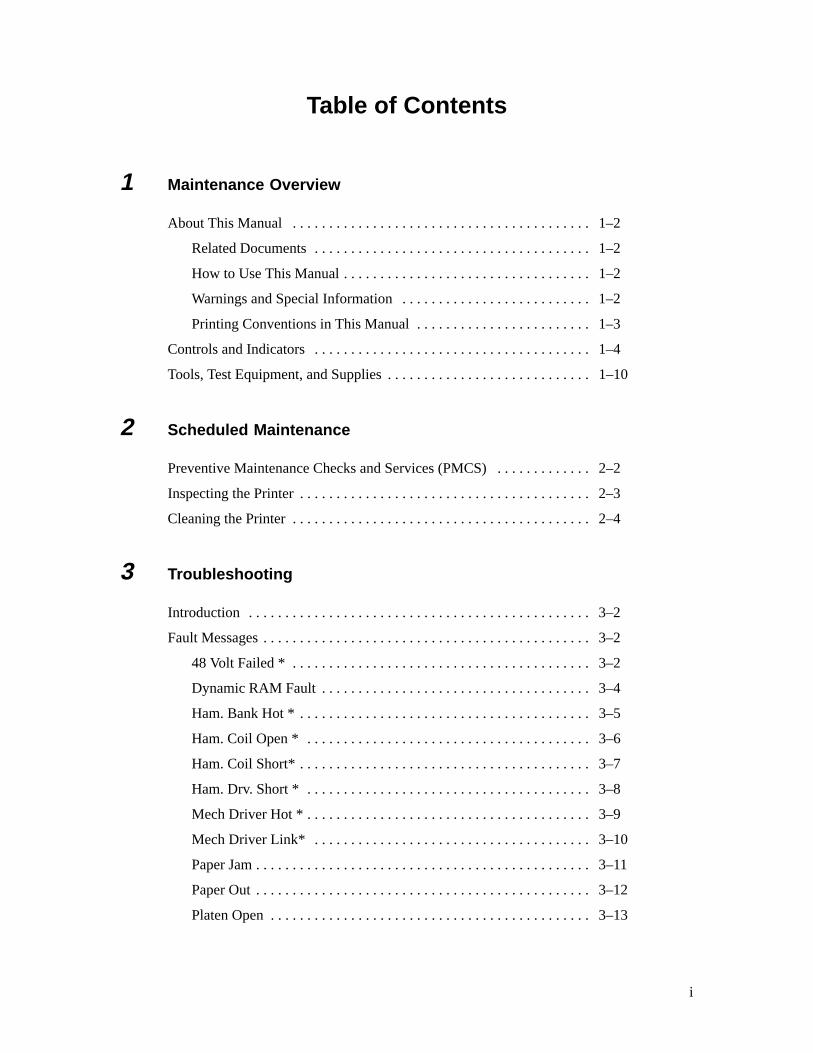
Table of Contents
1 Maintenance Overview
About This Manual 1–2. . . . . . . . . . . . . . . . . . . . . . . . . . . . . . . . . . . . . . . . .
Related Documents 1–2. . . . . . . . . . . . . . . . . . . . . . . . . . . . . . . . . . . . . .
How to Use This Manual 1–2. . . . . . . . . . . . . . . . . . . . . . . . . . . . . . . . . .
Warnings and Special Information 1–2. . . . . . . . . . . . . . . . . . . . . . . . . .
Printing Conventions in This Manual 1–3. . . . . . . . . . . . . . . . . . . . . . . .
Controls and Indicators 1–4. . . . . . . . . . . . . . . . . . . . . . . . . . . . . . . . . . . . . .
Tools, Test Equipment, and Supplies 1–10. . . . . . . . . . . . . . . . . . . . . . . . . . . .
2 Scheduled Maintenance
Preventive Maintenance Checks and Services (PMCS) 2–2. . . . . . . . . . . . .
Inspecting the Printer 2–3. . . . . . . . . . . . . . . . . . . . . . . . . . . . . . . . . . . . . . . .
Cleaning the Printer 2–4. . . . . . . . . . . . . . . . . . . . . . . . . . . . . . . . . . . . . . . . .
3 Troubleshooting
Introduction 3–2. . . . . . . . . . . . . . . . . . . . . . . . . . . . . . . . . . . . . . . . . . . . . . .
Fault Messages 3–2. . . . . . . . . . . . . . . . . . . . . . . . . . . . . . . . . . . . . . . . . . . . .
48 Volt Failed * 3–2. . . . . . . . . . . . . . . . . . . . . . . . . . . . . . . . . . . . . . . . .
Dynamic RAM Fault 3–4. . . . . . . . . . . . . . . . . . . . . . . . . . . . . . . . . . . . .
Ham. Bank Hot * 3–5. . . . . . . . . . . . . . . . . . . . . . . . . . . . . . . . . . . . . . . .
Ham. Coil Open * 3–6. . . . . . . . . . . . . . . . . . . . . . . . . . . . . . . . . . . . . . .
Ham. Coil Short* 3–7. . . . . . . . . . . . . . . . . . . . . . . . . . . . . . . . . . . . . . . .
Ham. Drv. Short * 3–8. . . . . . . . . . . . . . . . . . . . . . . . . . . . . . . . . . . . . . .
Mech Driver Hot * 3–9. . . . . . . . . . . . . . . . . . . . . . . . . . . . . . . . . . . . . . .
Mech Driver Link* 3–10. . . . . . . . . . . . . . . . . . . . . . . . . . . . . . . . . . . . . .
Paper Jam 3–11. . . . . . . . . . . . . . . . . . . . . . . . . . . . . . . . . . . . . . . . . . . . . .
Paper Out 3–12. . . . . . . . . . . . . . . . . . . . . . . . . . . . . . . . . . . . . . . . . . . . . .
Platen Open 3–13. . . . . . . . . . . . . . . . . . . . . . . . . . . . . . . . . . . . . . . . . . . .
ii
Ribbon Stall 3–14. . . . . . . . . . . . . . . . . . . . . . . . . . . . . . . . . . . . . . . . . . . .
Shttl Cover Open 3–15. . . . . . . . . . . . . . . . . . . . . . . . . . . . . . . . . . . . . . . .
Shuttle Jam 3–16. . . . . . . . . . . . . . . . . . . . . . . . . . . . . . . . . . . . . . . . . . . .
Software Error 3–17. . . . . . . . . . . . . . . . . . . . . . . . . . . . . . . . . . . . . . . . . .
Symptoms Not Indicated by Fault Messages 3–18. . . . . . . . . . . . . . . . . . . . . .
Troubleshooting Aids 3–19. . . . . . . . . . . . . . . . . . . . . . . . . . . . . . . . . . . . . . . .
Diagnostic Self–Tests 3–26. . . . . . . . . . . . . . . . . . . . . . . . . . . . . . . . . . . . . . . .
Running the Diagnostic Self–Tests 3–28. . . . . . . . . . . . . . . . . . . . . . . . . . . . .
Hex Code Printout 3–29. . . . . . . . . . . . . . . . . . . . . . . . . . . . . . . . . . . . . . . . . .
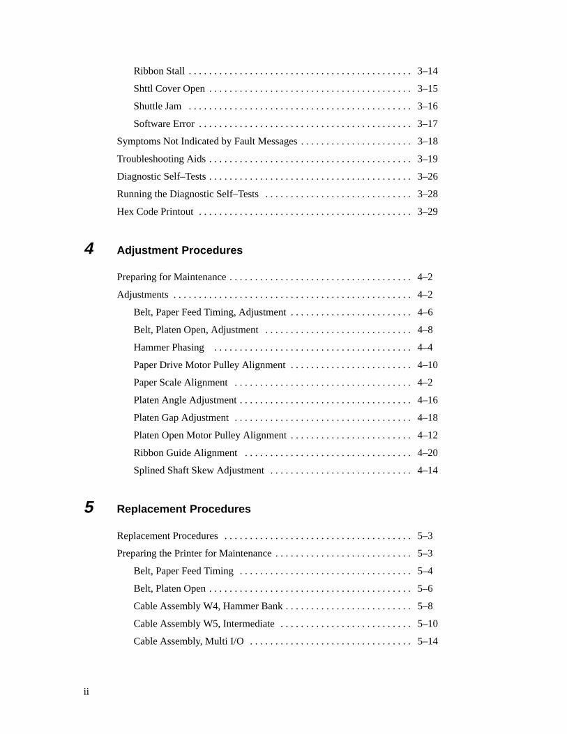
4 Adjustment Procedures
Preparing for Maintenance 4–2. . . . . . . . . . . . . . . . . . . . . . . . . . . . . . . . . . . .
Adjustments 4–2. . . . . . . . . . . . . . . . . . . . . . . . . . . . . . . . . . . . . . . . . . . . . . .
Belt, Paper Feed Timing, Adjustment 4–6. . . . . . . . . . . . . . . . . . . . . . . .
Belt, Platen Open, Adjustment 4–8. . . . . . . . . . . . . . . . . . . . . . . . . . . . .
Hammer Phasing 4–4. . . . . . . . . . . . . . . . . . . . . . . . . . . . . . . . . . . . . . .
Paper Drive Motor Pulley Alignment 4–10. . . . . . . . . . . . . . . . . . . . . . . .
Paper Scale Alignment 4–2. . . . . . . . . . . . . . . . . . . . . . . . . . . . . . . . . . .
Platen Angle Adjustment 4–16. . . . . . . . . . . . . . . . . . . . . . . . . . . . . . . . . .
Platen Gap Adjustment 4–18. . . . . . . . . . . . . . . . . . . . . . . . . . . . . . . . . . .
Platen Open Motor Pulley Alignment 4–12. . . . . . . . . . . . . . . . . . . . . . . .
Ribbon Guide Alignment 4–20. . . . . . . . . . . . . . . . . . . . . . . . . . . . . . . . .
Splined Shaft Skew Adjustment 4–14. . . . . . . . . . . . . . . . . . . . . . . . . . . .
5 Replacement Procedures
Replacement Procedures 5–3. . . . . . . . . . . . . . . . . . . . . . . . . . . . . . . . . . . . .
Preparing the Printer for Maintenance 5–3. . . . . . . . . . . . . . . . . . . . . . . . . . .
Belt, Paper Feed Timing 5–4. . . . . . . . . . . . . . . . . . . . . . . . . . . . . . . . . .
Belt, Platen Open 5–6. . . . . . . . . . . . . . . . . . . . . . . . . . . . . . . . . . . . . . . .
Cable Assembly W4, Hammer Bank 5–8. . . . . . . . . . . . . . . . . . . . . . . . .
Cable Assembly W5, Intermediate 5–10. . . . . . . . . . . . . . . . . . . . . . . . . .
Cable Assembly, Multi I/O 5–14. . . . . . . . . . . . . . . . . . . . . . . . . . . . . . . .

iii
Circuit Breaker 5–18. . . . . . . . . . . . . . . . . . . . . . . . . . . . . . . . . . . . . . . . .
Control Panel Assembly 5–20. . . . . . . . . . . . . . . . . . . . . . . . . . . . . . . . . .
Cover Assembly, Hammer Bank 5–22. . . . . . . . . . . . . . . . . . . . . . . . . . . .
Cover Assembly, Shuttle 5–24. . . . . . . . . . . . . . . . . . . . . . . . . . . . . . . . . .
Fan Assembly, Card Cage 5–26. . . . . . . . . . . . . . . . . . . . . . . . . . . . . . . . .
Fan Assembly, Cabinet Exhaust 5–28. . . . . . . . . . . . . . . . . . . . . . . . . . . .
Fan Assembly, Hammer Bank 5–30. . . . . . . . . . . . . . . . . . . . . . . . . . . . . .
Hammer Spring Assembly 5–32. . . . . . . . . . . . . . . . . . . . . . . . . . . . . . . .
Magnetic Pick–up (MPU) Assembly 5–34. . . . . . . . . . . . . . . . . . . . . . . . .
Motor Assembly, Ribbon Drive 5–36. . . . . . . . . . . . . . . . . . . . . . . . . . . . .
Motor Assembly, Paper Feed 5–38. . . . . . . . . . . . . . . . . . . . . . . . . . . . . . .
Motor Assembly, Platen Open 5–40. . . . . . . . . . . . . . . . . . . . . . . . . . . . . .
Paper Guide Assembly 5–42. . . . . . . . . . . . . . . . . . . . . . . . . . . . . . . . . . .
Paper Ironer 5–44. . . . . . . . . . . . . . . . . . . . . . . . . . . . . . . . . . . . . . . . . . . .
PCBA, Common Controller 5–46. . . . . . . . . . . . . . . . . . . . . . . . . . . . . . .
PCBA, Mechanism Driver 5–48. . . . . . . . . . . . . . . . . . . . . . . . . . . . . . . . .
PCBA, Power Supply 5–50. . . . . . . . . . . . . . . . . . . . . . . . . . . . . . . . . . . .
PROMs, Chips, and ICs on the CCB 5–52. . . . . . . . . . . . . . . . . . . . . . . . .
PROMs, Chips, and ICs on the Mechanism Driver 5–54. . . . . . . . . . . . . .
Resistors, Terminating 5–56. . . . . . . . . . . . . . . . . . . . . . . . . . . . . . . . . . . .
Ribbon Hub 5–58. . . . . . . . . . . . . . . . . . . . . . . . . . . . . . . . . . . . . . . . . . . .
Ribbon Guide Assembly (L/R) 5–60. . . . . . . . . . . . . . . . . . . . . . . . . . . . .
Shaft, Splined 5–62. . . . . . . . . . . . . . . . . . . . . . . . . . . . . . . . . . . . . . . . . .
Shaft, Support 5–64. . . . . . . . . . . . . . . . . . . . . . . . . . . . . . . . . . . . . . . . . .
Shuttle Frame Assembly 5–66. . . . . . . . . . . . . . . . . . . . . . . . . . . . . . . . . .
Spring Assembly, Gas 5–70. . . . . . . . . . . . . . . . . . . . . . . . . . . . . . . . . . . .
Spring, Extension 5–72. . . . . . . . . . . . . . . . . . . . . . . . . . . . . . . . . . . . . . .
Switch Assembly, Cover Open 5–74. . . . . . . . . . . . . . . . . . . . . . . . . . . . .
Switch Assembly, Paper Detector 5–76. . . . . . . . . . . . . . . . . . . . . . . . . . .
Switch Assembly, Platen Interlock 5–78. . . . . . . . . . . . . . . . . . . . . . . . . .
Tractor (L/R) 5–80. . . . . . . . . . . . . . . . . . . . . . . . . . . . . . . . . . . . . . . . . . .
Returning the Printer to Normal Operation 5–80. . . . . . . . . . . . . . . . . . . . . . .

iv
Appendices
A: Printer Configuration
B: Printer Specifications
C: Torque Table
D: Cable Interconnections and Hammer Bank Wiring
E: Principles of Operation
F: Ferrite Noise Suppression Cores
Index
1–1Maintenance Overview
1 Maintenance Overview
Chapter Contents
About This Manual 1–2. . . . . . . . . . . . . . . . . . . . . . . . . . . . . . . . . . . . . . . . . . . . . .
Related Documents 1–2. . . . . . . . . . . . . . . . . . . . . . . . . . . . . . . . . . . . . . . . . . .
How to Use This Manual 1–2. . . . . . . . . . . . . . . . . . . . . . . . . . . . . . . . . . . . . .
Warnings and Special Information 1–2. . . . . . . . . . . . . . . . . . . . . . . . . . . . . . .
Printing Conventions in This Manual 1–3. . . . . . . . . . . . . . . . . . . . . . . . . . . . .
Controls and Indicators 1–4. . . . . . . . . . . . . . . . . . . . . . . . . . . . . . . . . . . . . . . . . . .
Tools, Test Equipment, and Supplies 1–10. . . . . . . . . . . . . . . . . . . . . . . . . . . . . . . . .
1–2 Maintenance Overview
About This Manual
This manual explains how to maintain and repair the LG06 printer at the field
service level of maintenance. This manual covers alignments and
adjustments, preventive and corrective maintenance, troubleshooting, and
basic principles of operation.
Related Documents
Information about operating the LG06 printer is in the User’s Manual.
How to Use This Manual
This manual is designed so you can quickly find the information you need tomaintain and repair the Encore printer. You can locate maintenance
information three ways:
• Use the Table of Contents at the front of the manual.
• Use the Chapter Contents list on the first page of each chapter.
• Use the Index at the back of the manual.
Read the entire procedure before beginning any maintenance task. Gather allrequired tools and make sure you understand all warnings, cautions, and
notes before you begin working on the printer.
Warnings and Special Information
Always read and comply with information highlighted by special headings.
The headings reveal the nature of the information:
WARNING
Conditions that could harm you as well as damage the equipment.
CAUTION
Conditions that could damage the printer or related equipment.
IMPORTANT
Information vital to proper operation of the printer.
NOTE: Information considered important enough to emphasize.

1–3Maintenance Overview
Printing Conventions in This Manual
Switches and indicators labeled on the printer are printed uppercase in this
manual. Example: “Press the ON LINE switch to take the printer off–line.”
If a control is not labeled on the printer, it is printed lowercase. Example:
“Set the forms thickness lever to the fully open position.”
Messages that appear on the control panel display are printed inside
quotation marks in lowercase with the first letter capitalized. Example: “Save
Config” appears on the message display.

1–4 Maintenance Overview
Controls and Indicators
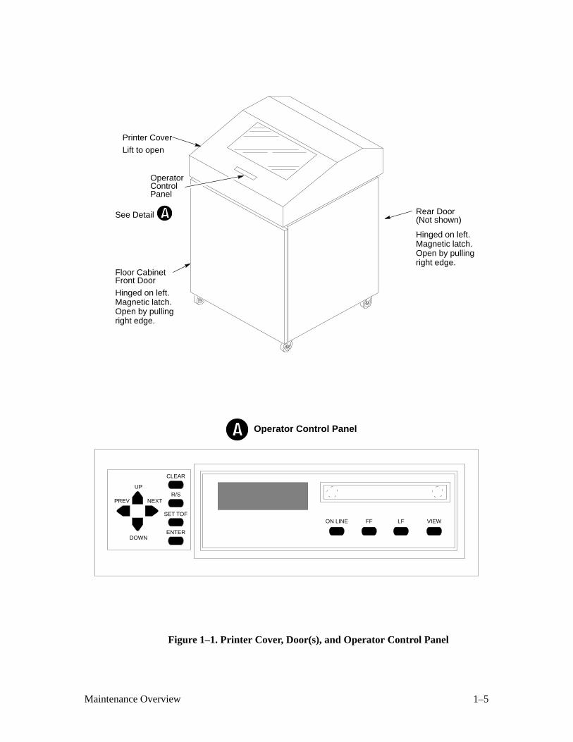
The locations of the printer cover, cabinet doors, and operator control panel
are shown in Figure 1–1.
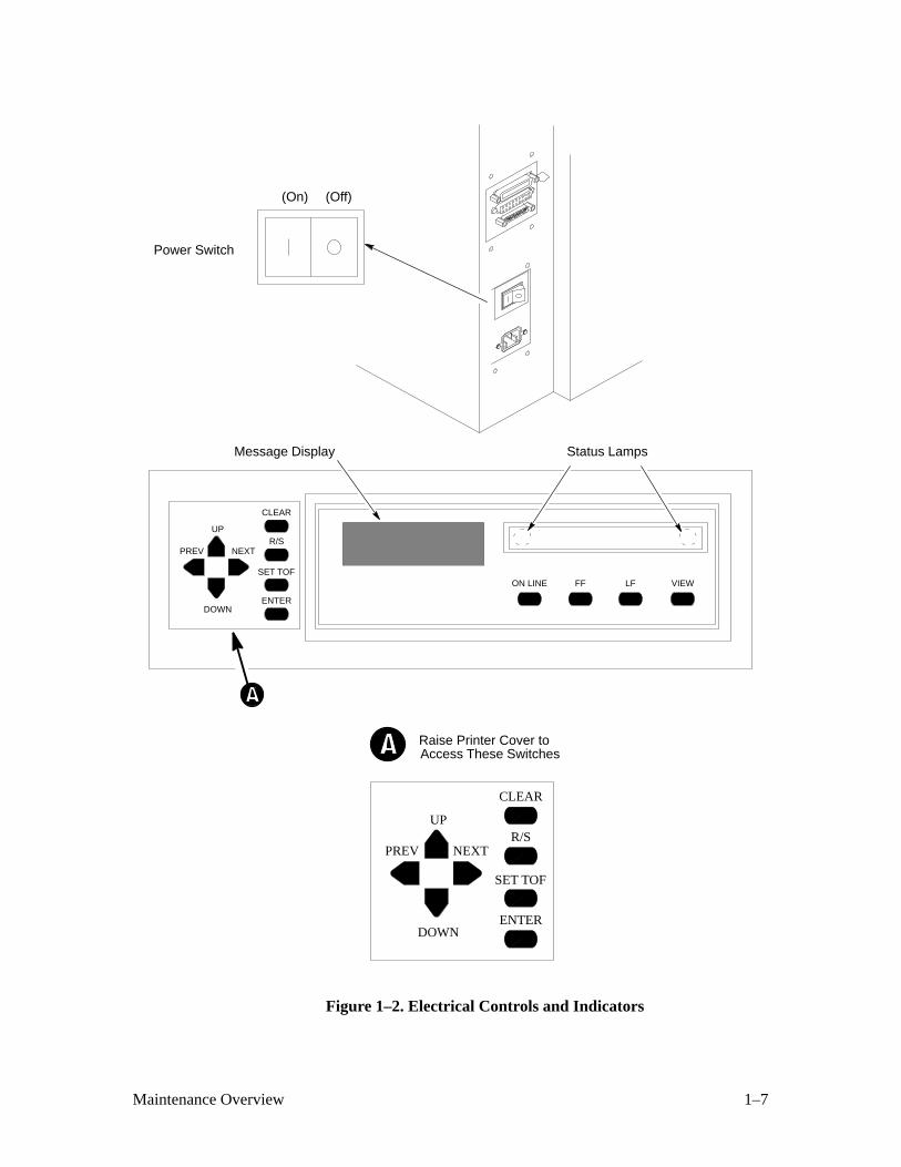
Electrical controls and indicators are described in Table 1–1 and illustrated in
Figure 1–2.
Mechanical controls and indicators are described in Table 1–2 and illustratedin Figure 1–3.
1–5Maintenance Overview
Hinged on left.Magnetic latch.Open by pullingright edge.
Lift to open
(Not shown)
Hinged on left.Magnetic latch.Open by pullingright edge.
ON LINE FF VIEW
ENTER
CLEAR
R/S
SET TOFLF
NEXTPREV
DOWN
UP
Operator Control Panel
Floor CabinetFront Door
Printer Cover
Rear Door
OperatorControlPanel
See Detail
Figure 1–1. Printer Cover, Door(s), and Operator Control Panel
1–6 Maintenance Overview
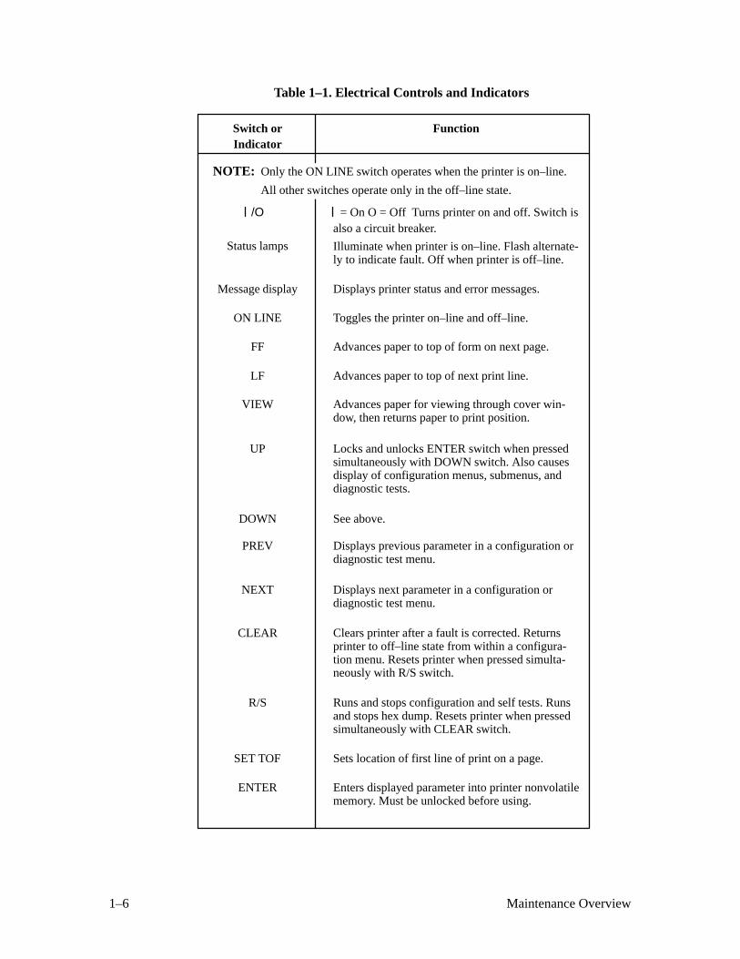
Table 1–1. Electrical Controls and Indicators
Switch or
/O
ON LINE
Message display
LF
Function
= On O = Off Turns printer on and off. Switch is
Toggles the printer on–line and off–line.
Displays printer status and error messages.
Indicator
Status lamps
FF Advances paper to top of form on next page.
VIEW
UP
DOWN See above.
PREV
NEXT
Locks and unlocks ENTER switch when pressedsimultaneously with DOWN switch. Also causesdisplay of configuration menus, submenus, anddiagnostic tests.
R/S
ENTER
Displays previous parameter in a configuration ordiagnostic test menu.
Illuminate when printer is on–line. Flash alternate-ly to indicate fault. Off when printer is off–line.
Advances paper to top of next print line.
Runs and stops configuration and self tests. Runsand stops hex dump. Resets printer when pressedsimultaneously with CLEAR switch.
Enters displayed parameter into printer nonvolatilememory. Must be unlocked before using.
Clears printer after a fault is corrected. Returnsprinter to off–line state from within a configura-tion menu. Resets printer when pressed simulta-neously with R/S switch.
Displays next parameter in a configuration ordiagnostic test menu.
Advances paper for viewing through cover win-dow, then returns paper to print position.
CLEAR
SET TOF Sets location of first line of print on a page.
NOTE: Only the ON LINE switch operates when the printer is on–line.
All other switches operate only in the off–line state.
also a circuit breaker.
1–7Maintenance Overview
Raise Printer Cover to Access These Switches
ON LINE FF VIEW
ENTER
CLEAR
R/S
SET TOFLF
NEXTPREV
DOWN
UP
ENTER
CLEAR
R/S
SET TOF
NEXTPREV
DOWN
UP
Status LampsMessage Display
(On) (Off)
Power Switch
Figure 1–2. Electrical Controls and Indicators
1–8 Maintenance Overview
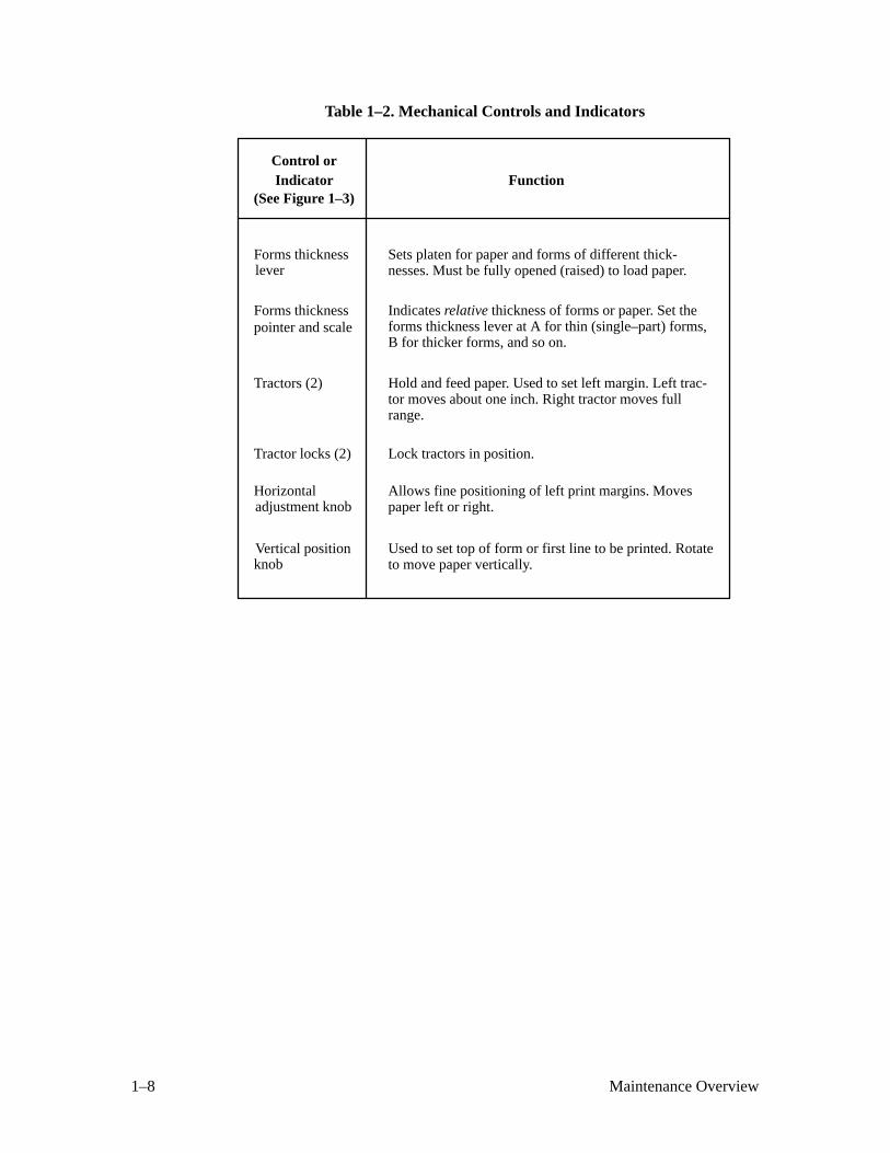
Table 1–2. Mechanical Controls and Indicators
Control orFunctionIndicator
Forms thicknesslever
Forms thicknesspointer and scale
Tractors (2)
Tractor locks (2)
Horizontal adjustment knob
Vertical positionknob
Lock tractors in position.
Sets platen for paper and forms of different thick-nesses. Must be fully opened (raised) to load paper.
Hold and feed paper. Used to set left margin. Left trac-tor moves about one inch. Right tractor moves fullrange.
Allows fine positioning of left print margins. Movespaper left or right.
Used to set top of form or first line to be printed. Rotateto move paper vertically.
(See Figure 1–3)
Indicates relative thickness of forms or paper. Set theforms thickness lever at A for thin (single–part) forms,B for thicker forms, and so on.
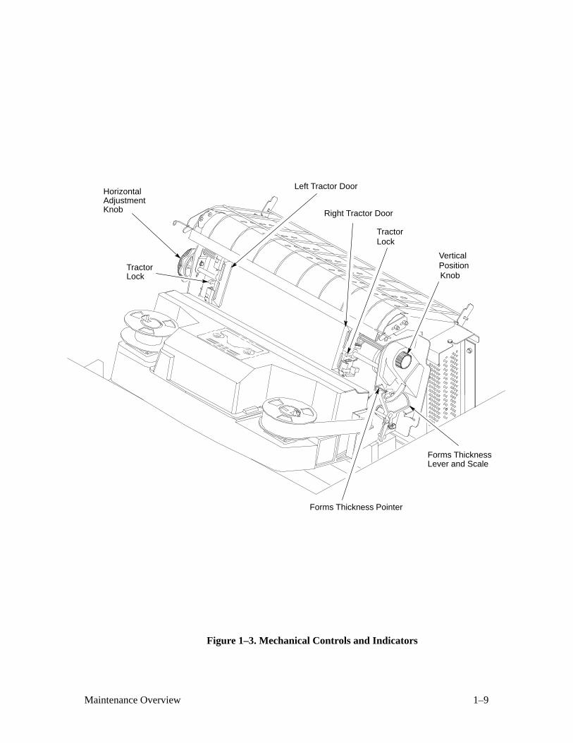
1–9Maintenance Overview
VerticalPositionKnob
TractorLock
Left Tractor Door
Right Tractor Door
HorizontalAdjustmentKnob
TractorLock
Forms Thickness Pointer
Forms ThicknessLever and Scale
Figure 1–3. Mechanical Controls and Indicators
1–10 Maintenance Overview
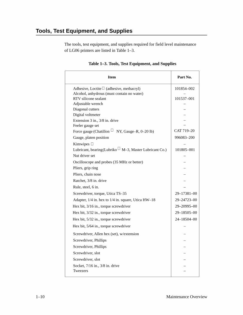
Tools, Test Equipment, and Supplies
The tools, test equipment, and supplies required for field level maintenance
of LG06 printers are listed in Table 1–3.
Table 1–3. Tools, Test Equipment, and Supplies
Item Part No.
RTV silicone sealantAdjustable wrenchDiagonal cuttersDigital voltmeter
Extension 3 in., 3/8 in. driveFeeler gauge set
Alcohol, anhydrous (must contain no water)
Kimwipes
Nut driver set
Oscilloscope and probes (35 MHz or better)
Pliers, grip ring
Pliers, chain nose
Ratchet, 3/8 in. drive
Rule, steel, 6 in.
Screwdriver, torque, Utica TS–35
Adapter, 1/4 in. hex to 1/4 in. square, Utica HW–18
Hex bit, 3/32 in., torque screwdriver
Hex bit, 5/32 in., torque screwdriver
Screwdriver, Allen hex (set), w/extension
Screwdriver, Phillips
Screwdriver, Phillips
Screwdriver, slot
Screwdriver, slot
Socket, 7/16 in., 3/8 in. drive
101537–001–––––
–
–
–
–
–
–
–
–
29–17381–00
29–24723–00
29–18505–00
24–18504–00
–
–
–
–
–
–
Adhesive, Loctite 101854–002
Lubricant, bearing 101805–001
Force gauge CAT 719–20
Gauge, platen position 996083–200
Tweezers –
(adhesive, methacryl)
(Chatillon NY, Gauge–R, 0–20 lb)
(Lubriko M–3, Master Lubricant Co.)
Hex bit, 5/64 in., torque screwdriver –
Hex bit, 3/16 in., torque screwdriver 29–20995–00
2–1Scheduled Maintenance
2 Scheduled Maintenance
Chapter Contents
Preventive Maintenance Checks and Services (PMCS) 2–2. . . . . . . . . . . . . . . . . .
Inspecting the Printer 2–3. . . . . . . . . . . . . . . . . . . . . . . . . . . . . . . . . . . . . . . . . . . . .
Cleaning the Printer 2–4. . . . . . . . . . . . . . . . . . . . . . . . . . . . . . . . . . . . . . . . . . . . . .
2–2 Scheduled Maintenance
Preventive Maintenance Checks and Services (PMCS)
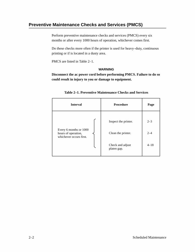
Perform preventive maintenance checks and services (PMCS) every six
months or after every 1000 hours of operation, whichever comes first.
Do these checks more often if the printer is used for heavy–duty, continuous
printing or if is located in a dusty area.
PMCS are listed in Table 2–1.
WARNING
Disconnect the ac power cord before performing PMCS. Failure to do socould result in injury to you or damage to equipment.
Table 2–1. Preventive Maintenance Checks and Services
Interval Procedure
Inspect the printer.
Clean the printer.
Check and adjustplaten gap.
Every 6 months or 1000hours of operation,whichever occurs first.
Page
2–3
2–4
4–18
2–3Scheduled Maintenance
Inspecting the Printer
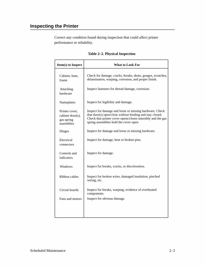
Correct any condition found during inspection that could affect printer
performance or reliability.
Table 2–2. Physical Inspection
Item(s) to Inspect
Cabinet, base,frame
Attaching hardware
Nameplates
Printer cover,cabinet door(s),gas spring
Hinges
Electricalconnectors
Controls andindicators
Windows
Ribbon cables
Circuit boards
Fans and motors
What to Look For
Check for damage, cracks, breaks, dents, gouges, scratches,delamination, warping, corrosion, and proper finish.
Inspect fasteners for thread damage, corrosion.
Inspect for legibility and damage.
Inspect for damage and loose or missing hardware. Checkthat door(s) open/close without binding and stay closed.Check that printer cover opens/closes smoothly and the gasspring assemblies hold the cover open.
Inspect for damage and loose or missing hardware.
Inspect for damage, bent or broken pins.
Inspect for damage.
Inspect for breaks, cracks, or discoloration.
Inspect for broken wires, damaged insulation, pinchedwiring, etc.
Inspect for breaks, warping, evidence of overheatedcomponents.
Inspect for obvious damage.
assemblies
2–4 Scheduled Maintenance
Cleaning the Printer
CAUTION
Do not use abrasive cleaners, particularly on the window. Do not dripwater into the printer. Damage to the equipment will result. When usingspray solutions, do not spray directly onto the printer; spray the cloth,then apply the dampened cloth to the printer.
Cleaning Outside the Cabinet
1. Wipe the cabinet with a clean, lint–free cloth dampened (not wet) with
water and mild detergent or window cleaning solution.
2. Dry the cabinet with a clean, lint–free cloth.
3. Clean the inside of the cabinet. (See below.)
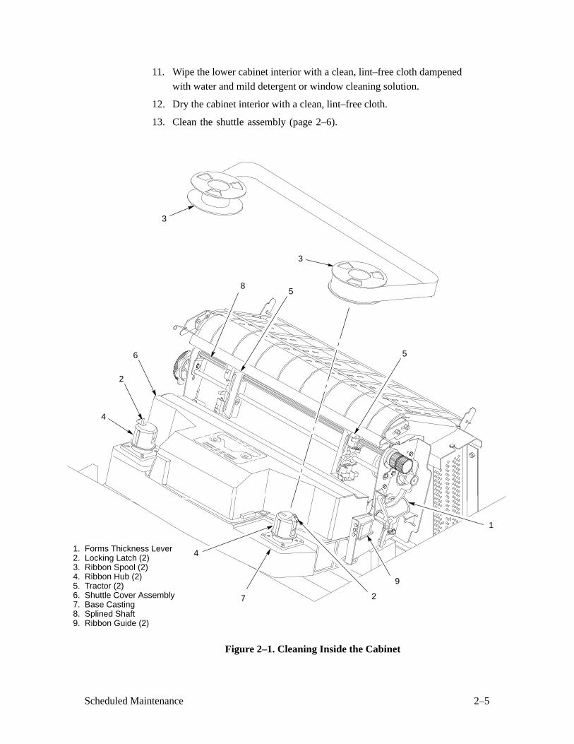
Cleaning Inside the Cabinet (Figure 2–1)
1. Set the power switch to the O (off) position.
2. Disconnect the ac power cord from the printer.
3. Open the printer cover.
4. Move the forms thickness adjustment lever (1) to the fully–open
position.
5. Remove paper from the printer.
6. Squeeze the locking latch (2) and lift the ribbon spools (3) from the
ribbon hubs (4).
7. Using a soft–bristled brush, wipe off paper dust and ribbon lint. Vacuum
up the residue. Pay particular attention to the tractors (5), shuttle cover
assembly (6), and base casting (7).
8. Wipe the splined shaft (8) with a soft cloth.
CAUTION
To avoid corrosion damage, use only anhydrous alcohol when cleaningprinter mechanical elements. The cleaning solution must contain nowater.
9. Using a cloth dampened with anhydrous alcohol, clean the ribbon guides
(9).
10. Vacuum up dust or residue that has accumulated inside the lower
cabinet.
2–5Scheduled Maintenance
11. Wipe the lower cabinet interior with a clean, lint–free cloth dampened
with water and mild detergent or window cleaning solution.
12. Dry the cabinet interior with a clean, lint–free cloth.
13. Clean the shuttle assembly (page 2–6).
1. Forms Thickness Lever2. Locking Latch (2)3. Ribbon Spool (2)4. Ribbon Hub (2)5. Tractor (2)6. Shuttle Cover Assembly7. Base Casting8. Splined Shaft9. Ribbon Guide (2)
8
1
9
7
5
2
4
2
4
6
5
3
3
Figure 2–1. Cleaning Inside the Cabinet
2–6 Scheduled Maintenance
Cleaning the Shuttle Frame Assembly (Figure 2–2)
1. Remove the shuttle cover assembly (page 5–24).
2. Remove the shuttle frame assembly (page 5–66).
3. Remove the paper ironer (page 5–44).
WARNING
Over time, the upper edge of the paper ironer can become sharp. Toavoid cutting yourself, handle the paper ironer on the sides.
4. Moisten a clean, soft cloth with anhydrous alcohol. Wipe the paperironer to remove lint, ink, and paper residue.
5. Install the paper ironer (page 5–44).
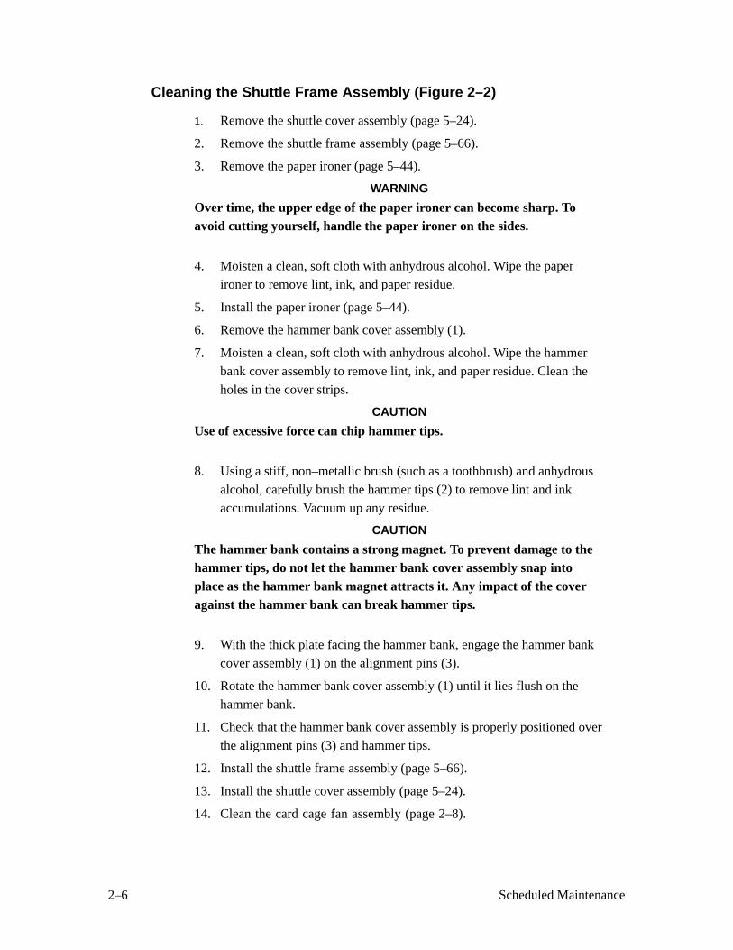
6. Remove the hammer bank cover assembly (1).
7. Moisten a clean, soft cloth with anhydrous alcohol. Wipe the hammer
bank cover assembly to remove lint, ink, and paper residue. Clean the
holes in the cover strips.
CAUTION
Use of excessive force can chip hammer tips.
8. Using a stiff, non–metallic brush (such as a toothbrush) and anhydrous
alcohol, carefully brush the hammer tips (2) to remove lint and ink
accumulations. Vacuum up any residue.
CAUTION
The hammer bank contains a strong magnet. To prevent damage to thehammer tips, do not let the hammer bank cover assembly snap intoplace as the hammer bank magnet attracts it. Any impact of the coveragainst the hammer bank can break hammer tips.
9. With the thick plate facing the hammer bank, engage the hammer bank
cover assembly (1) on the alignment pins (3).
10. Rotate the hammer bank cover assembly (1) until it lies flush on the
hammer bank.
11. Check that the hammer bank cover assembly is properly positioned over
the alignment pins (3) and hammer tips.
12. Install the shuttle frame assembly (page 5–66).
13. Install the shuttle cover assembly (page 5–24).
14. Clean the card cage fan assembly (page 2–8).
2–7Scheduled Maintenance
Hammer Tip
Hammer Bank
Roll pin (2)(Not shown)
Thin plate
Thick plate
Cover Assembly
Figure 2–2. Cleaning the Shuttle Frame Assembly
2–8 Scheduled Maintenance
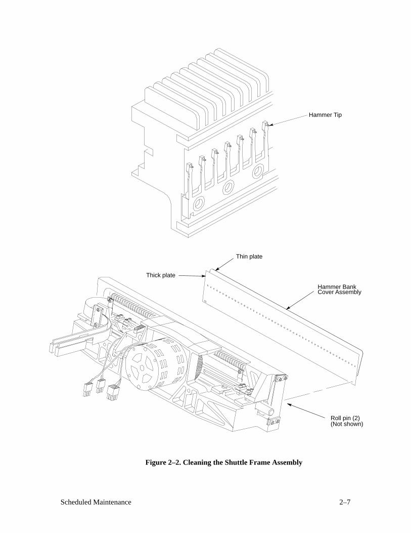
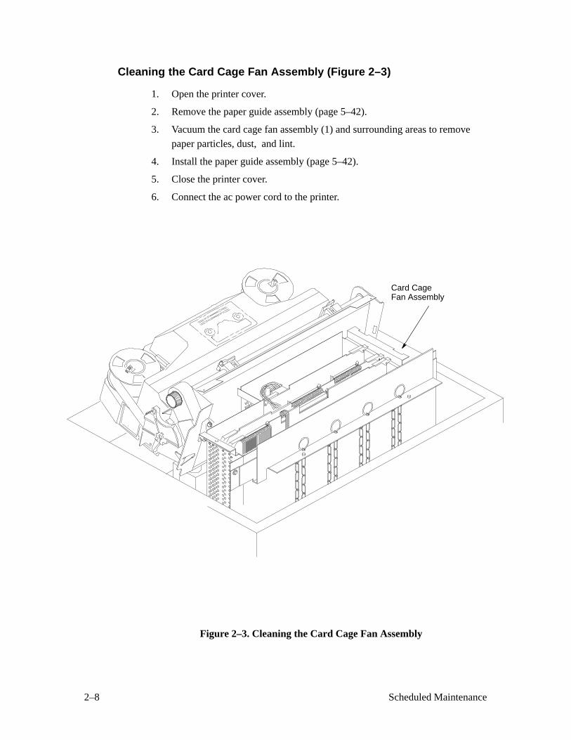
Cleaning the Card Cage Fan Assembly (Figure 2–3)
1. Open the printer cover.
2. Remove the paper guide assembly (page 5–42).
3. Vacuum the card cage fan assembly (1) and surrounding areas to removepaper particles, dust, and lint.
4. Install the paper guide assembly (page 5–42).
5. Close the printer cover.
6. Connect the ac power cord to the printer.
Card CageFan Assembly
Figure 2–3. Cleaning the Card Cage Fan Assembly
3–1Troubleshooting
3 Troubleshooting
Chapter Contents
Introduction 3–2. . . . . . . . . . . . . . . . . . . . . . . . . . . . . . . . . . . . . . . . . . . . . . . . . . . .
Fault Messages 3–2. . . . . . . . . . . . . . . . . . . . . . . . . . . . . . . . . . . . . . . . . . . . . . . . .
48 Volt Failed * 3–2. . . . . . . . . . . . . . . . . . . . . . . . . . . . . . . . . . . . . . . . . . . . . .
Dynamic RAM Fault 3–4. . . . . . . . . . . . . . . . . . . . . . . . . . . . . . . . . . . . . . . . . .
Ham. Bank Hot * 3–5. . . . . . . . . . . . . . . . . . . . . . . . . . . . . . . . . . . . . . . . . . . .
Ham. Coil Open * 3–6. . . . . . . . . . . . . . . . . . . . . . . . . . . . . . . . . . . . . . . . . . . .
Ham. Coil Short * 3–7. . . . . . . . . . . . . . . . . . . . . . . . . . . . . . . . . . . . . . . . . . . .
Ham. Drv. Short * 3–8. . . . . . . . . . . . . . . . . . . . . . . . . . . . . . . . . . . . . . . . . . . .
Mech Driver Hot * 3–9. . . . . . . . . . . . . . . . . . . . . . . . . . . . . . . . . . . . . . . . . . .
Mech Driver Link * 3–10. . . . . . . . . . . . . . . . . . . . . . . . . . . . . . . . . . . . . . . . . .
Paper Jam 3–11. . . . . . . . . . . . . . . . . . . . . . . . . . . . . . . . . . . . . . . . . . . . . . . . . .
Paper Out 3–12. . . . . . . . . . . . . . . . . . . . . . . . . . . . . . . . . . . . . . . . . . . . . . . . . .
Platen Open 3–13. . . . . . . . . . . . . . . . . . . . . . . . . . . . . . . . . . . . . . . . . . . . . . . . .
Ribbon Stall 3–14. . . . . . . . . . . . . . . . . . . . . . . . . . . . . . . . . . . . . . . . . . . . . . . .
Shttl Cover Open 3–15. . . . . . . . . . . . . . . . . . . . . . . . . . . . . . . . . . . . . . . . . . . . .
Shuttle Jam 3–16. . . . . . . . . . . . . . . . . . . . . . . . . . . . . . . . . . . . . . . . . . . . . . . . .
Software Error 3–17. . . . . . . . . . . . . . . . . . . . . . . . . . . . . . . . . . . . . . . . . . . . . . .
Symptoms Not Indicated by Fault Messages 3–18. . . . . . . . . . . . . . . . . . . . . . . . . .
Troubleshooting Aids 3–19. . . . . . . . . . . . . . . . . . . . . . . . . . . . . . . . . . . . . . . . . . . .
Diagnostic Self–Tests 3–26. . . . . . . . . . . . . . . . . . . . . . . . . . . . . . . . . . . . . . . . . . . .
Running the Diagnostic Self–Tests 3–28. . . . . . . . . . . . . . . . . . . . . . . . . . . . . . . . . .
Hex Code Printout 3–29. . . . . . . . . . . . . . . . . . . . . . . . . . . . . . . . . . . . . . . . . . . . . . .
3–2 Troubleshooting
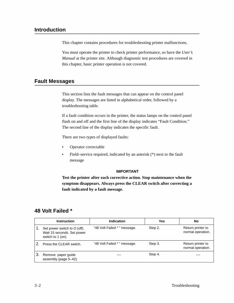
Introduction
This chapter contains procedures for troubleshooting printer malfunctions.
You must operate the printer to check printer performance, so have the User’s
Manual at the printer site. Although diagnostic test procedures are covered in
this chapter, basic printer operation is not covered.
Fault Messages
This section lists the fault messages that can appear on the control panel
display. The messages are listed in alphabetical order, followed by a
troubleshooting table.
If a fault condition occurs in the printer, the status lamps on the control panel
flash on and off and the first line of the display indicates “Fault Condition.”
The second line of the display indicates the specific fault.
There are two types of displayed faults:
• Operator correctable
• Field–service required, indicated by an asterisk (*) next to the fault
message
IMPORTANT
Test the printer after each corrective action. Stop maintenance when thesymptom disappears. Always press the CLEAR switch after correcting afault indicated by a fault message.
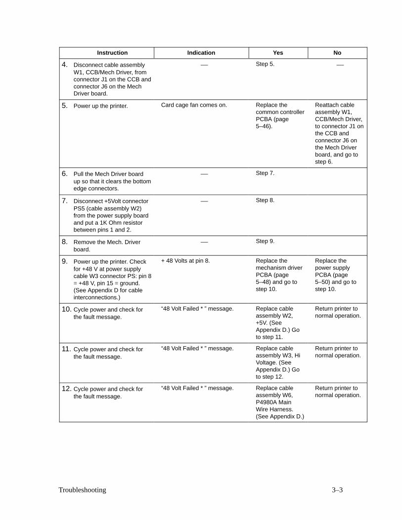
48 Volt Failed *
Instruction Indication Yes No
1. Set power switch to O (off).Wait 15 seconds. Set powerswitch to 1 (on).
“48 Volt Failed * ” message. Step 2. Return printer tonormal operation.
2. Press the CLEAR switch. “48 Volt Failed * ” message. Step 3. Return printer tonormal operation.
3. Remove paper guideassembly (page 5–42).
— Step 4. —
3–3Troubleshooting
Instruction NoYesIndication
4. Disconnect cable assemblyW1, CCB/Mech Driver, fromconnector J1 on the CCB andconnector J6 on the MechDriver board.
— Step 5. —
5. Power up the printer. Card cage fan comes on. Replace thecommon controllerPCBA (page5–46).
Reattach cableassembly W1,CCB/Mech Driver,to connector J1 onthe CCB andconnector J6 onthe Mech Driverboard, and go tostep 6.
6. Pull the Mech Driver boardup so that it clears the bottomedge connectors.
— Step 7.
7. Disconnect +5Volt connectorPS5 (cable assembly W2)from the power supply boardand put a 1K Ohm resistorbetween pins 1 and 2.
— Step 8.
8. Remove the Mech. Driverboard.
— Step 9.
9. Power up the printer. Checkfor +48 V at power supplycable W3 connector PS: pin 8= +48 V, pin 15 = ground.(See Appendix D for cableinterconnections.)
+ 48 Volts at pin 8. Replace themechanism driverPCBA (page5–48) and go tostep 10.
Replace thepower supplyPCBA (page5–50) and go tostep 10.
10. Cycle power and check forthe fault message.
“48 Volt Failed * ” message. Replace cableassembly W2,+5V. (SeeAppendix D.) Goto step 11.
Return printer tonormal operation.
11. Cycle power and check forthe fault message.
“48 Volt Failed * ” message. Replace cableassembly W3, HiVoltage. (SeeAppendix D.) Goto step 12.
Return printer tonormal operation.
12. Cycle power and check forthe fault message.
“48 Volt Failed * ” message. Replace cableassembly W6,P4980A MainWire Harness.(See Appendix D.)
Return printer tonormal operation.
3–4 Troubleshooting
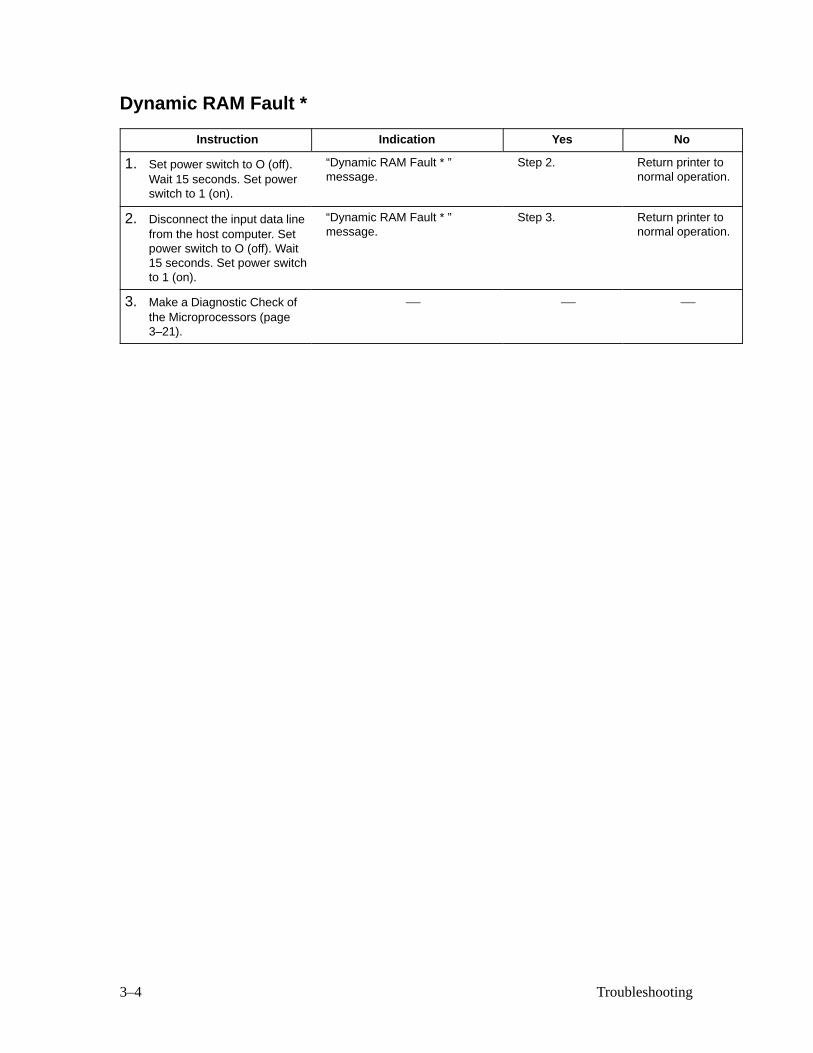
Dynamic RAM Fault *
Instruction Indication Yes No
1. Set power switch to O (off).Wait 15 seconds. Set powerswitch to 1 (on).
“Dynamic RAM Fault * ”message.
Step 2. Return printer tonormal operation.
2. Disconnect the input data linefrom the host computer. Setpower switch to O (off). Wait15 seconds. Set power switchto 1 (on).
“Dynamic RAM Fault * ”message.
Step 3. Return printer tonormal operation.
3. Make a Diagnostic Check ofthe Microprocessors (page3–21).
— — —
3–5Troubleshooting
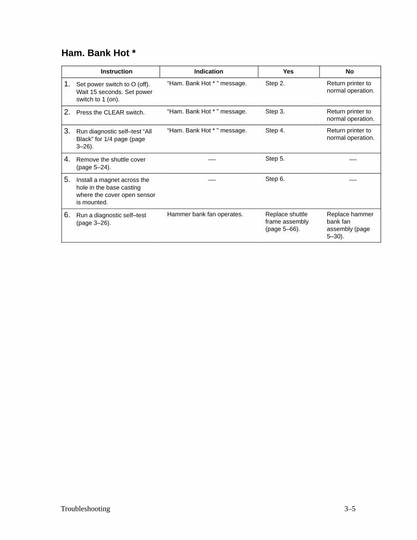
Ham. Bank Hot *
Instruction Indication Yes No
1. Set power switch to O (off).Wait 15 seconds. Set powerswitch to 1 (on).
“Ham. Bank Hot * ” message. Step 2. Return printer tonormal operation.
2. Press the CLEAR switch. “Ham. Bank Hot * ” message. Step 3. Return printer tonormal operation.
3. Run diagnostic self–test “AllBlack” for 1/4 page (page3–26).
“Ham. Bank Hot * ” message. Step 4. Return printer tonormal operation.
4. Remove the shuttle cover(page 5–24).
— Step 5. —
5. Install a magnet across thehole in the base castingwhere the cover open sensoris mounted.
— Step 6. —
6. Run a diagnostic self–test(page 3–26).
Hammer bank fan operates. Replace shuttleframe assembly(page 5–66).
Replace hammerbank fanassembly (page5–30).
3–6 Troubleshooting
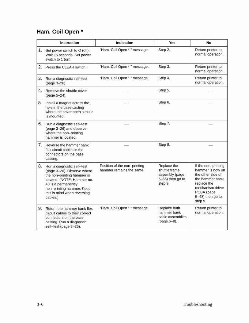
Ham. Coil Open *
Instruction Indication Yes No
1. Set power switch to O (off).Wait 15 seconds. Set powerswitch to 1 (on).
“Ham. Coil Open * ” message. Step 2. Return printer tonormal operation.
2. Press the CLEAR switch. “Ham. Coil Open * ” message. Step 3. Return printer tonormal operation.
3. Run a diagnostic self–test(page 3–26).
“Ham. Coil Open * ” message. Step 4. Return printer tonormal operation.
4. Remove the shuttle cover(page 5–24).
— Step 5. —
5. Install a magnet across thehole in the base castingwhere the cover open sensoris mounted.
— Step 6. —
6. Run a diagnostic self–test(page 3–26) and observewhere the non–printinghammer is located.
— Step 7. —
7. Reverse the hammer bankflex circuit cables in theconnectors on the basecasting.
— Step 8. —
8. Run a diagnostic self–test(page 3–26). Observe wherethe non–printing hammer islocated. (NOTE: Hammer no.48 is a permanentlynon–printing hammer. Keepthis is mind when reversingcables.)
Position of the non–printinghammer remains the same.
Replace theshuttle frameassembly (page5–66) then go tostep 9.
If the non–printinghammer is now onthe other side ofthe hammer bank,replace themechanism driverPCBA (page5–48) then go tostep 9.
9. Return the hammer bank flexcircuit cables to their correctconnectors on the basecasting. Run a diagnosticself–test (page 3–26).
“Ham. Coil Open * ” message. Replace bothhammer bankcable assemblies(page 5–8).
Return printer tonormal operation.
3–7Troubleshooting
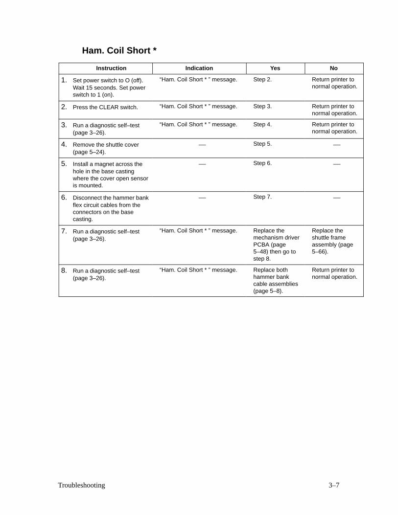
Ham. Coil Short *
Instruction Indication Yes No
1. Set power switch to O (off).Wait 15 seconds. Set powerswitch to 1 (on).
“Ham. Coil Short * ” message. Step 2. Return printer tonormal operation.
2. Press the CLEAR switch. “Ham. Coil Short * ” message. Step 3. Return printer tonormal operation.
3. Run a diagnostic self–test(page 3–26).
“Ham. Coil Short * ” message. Step 4. Return printer tonormal operation.
4. Remove the shuttle cover(page 5–24).
— Step 5. —
5. Install a magnet across thehole in the base castingwhere the cover open sensoris mounted.
— Step 6. —
6. Disconnect the hammer bankflex circuit cables from theconnectors on the basecasting.
— Step 7. —
7. Run a diagnostic self–test(page 3–26).
“Ham. Coil Short * ” message. Replace themechanism driverPCBA (page5–48) then go tostep 8.
Replace theshuttle frameassembly (page5–66).
8. Run a diagnostic self–test(page 3–26).
“Ham. Coil Short * ” message. Replace bothhammer bankcable assemblies(page 5–8).
Return printer tonormal operation.
3–8 Troubleshooting
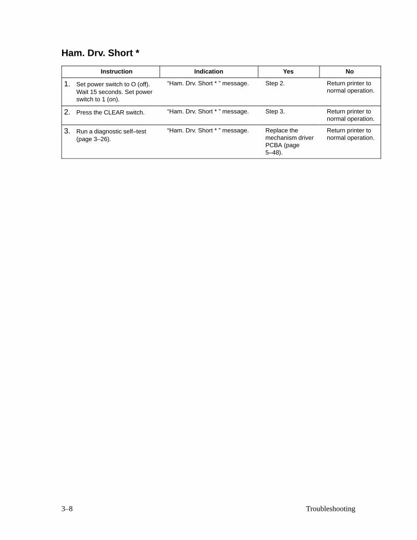
Ham. Drv. Short *
Instruction Indication Yes No
1. Set power switch to O (off).Wait 15 seconds. Set powerswitch to 1 (on).
“Ham. Drv. Short * ” message. Step 2. Return printer tonormal operation.
2. Press the CLEAR switch. “Ham. Drv. Short * ” message. Step 3. Return printer tonormal operation.
3. Run a diagnostic self–test(page 3–26).
“Ham. Drv. Short * ” message. Replace themechanism driverPCBA (page5–48).
Return printer tonormal operation.
3–9Troubleshooting
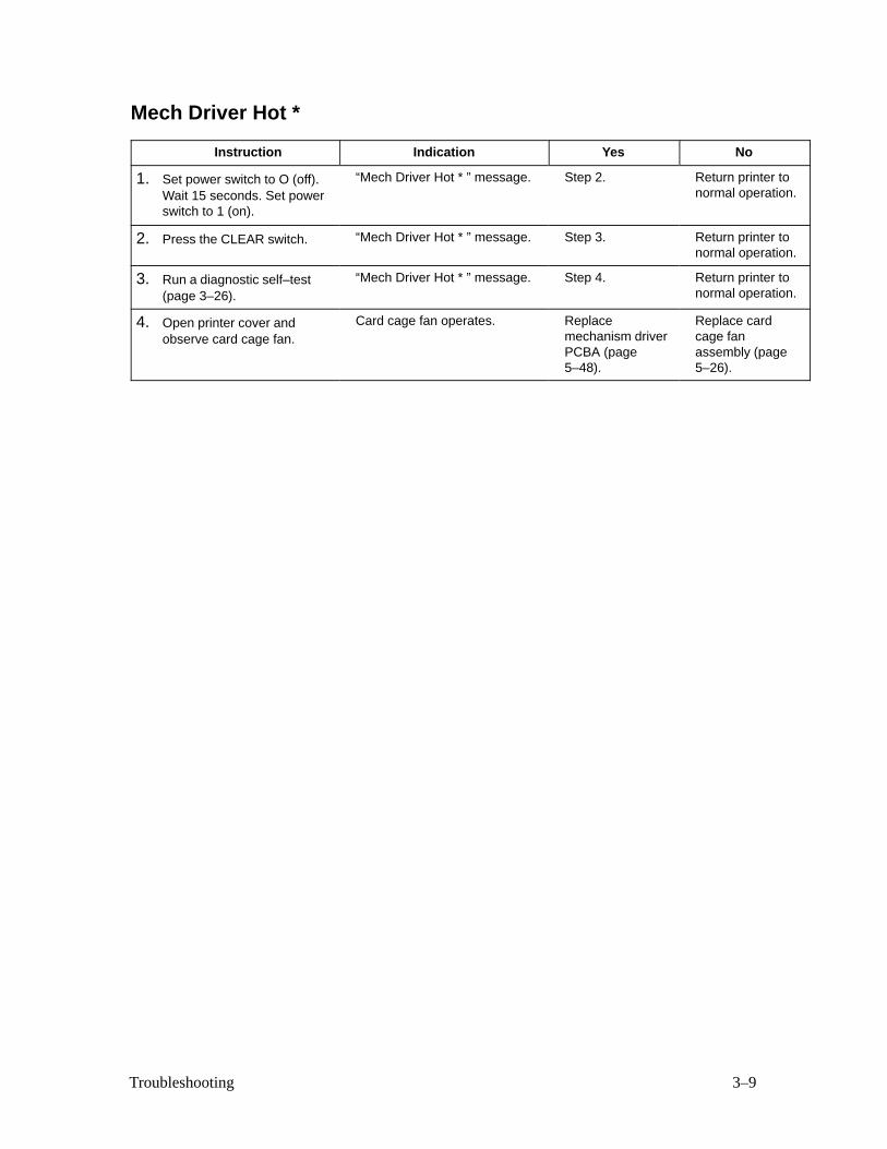
Mech Driver Hot *
Instruction Indication Yes No
1. Set power switch to O (off).Wait 15 seconds. Set powerswitch to 1 (on).
“Mech Driver Hot * ” message. Step 2. Return printer tonormal operation.
2. Press the CLEAR switch. “Mech Driver Hot * ” message. Step 3. Return printer tonormal operation.
3. Run a diagnostic self–test(page 3–26).
“Mech Driver Hot * ” message. Step 4. Return printer tonormal operation.
4. Open printer cover andobserve card cage fan.
Card cage fan operates. Replacemechanism driverPCBA (page5–48).
Replace cardcage fanassembly (page5–26).
3–10 Troubleshooting
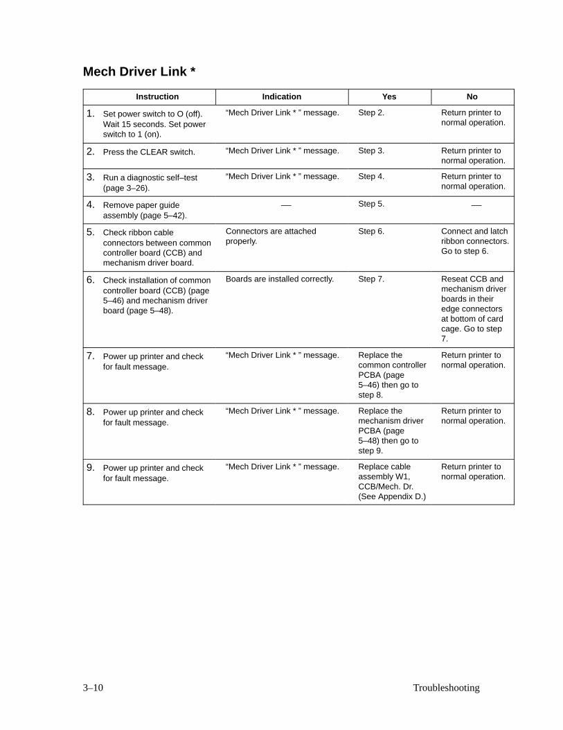
Mech Driver Link *
Instruction Indication Yes No
1. Set power switch to O (off).Wait 15 seconds. Set powerswitch to 1 (on).
“Mech Driver Link * ” message. Step 2. Return printer tonormal operation.
2. Press the CLEAR switch. “Mech Driver Link * ” message. Step 3. Return printer tonormal operation.
3. Run a diagnostic self–test(page 3–26).
“Mech Driver Link * ” message. Step 4. Return printer tonormal operation.
4. Remove paper guideassembly (page 5–42).
— Step 5. —
5. Check ribbon cableconnectors between commoncontroller board (CCB) andmechanism driver board.
Connectors are attachedproperly.
Step 6. Connect and latchribbon connectors.Go to step 6.
6. Check installation of commoncontroller board (CCB) (page5–46) and mechanism driverboard (page 5–48).
Boards are installed correctly. Step 7. Reseat CCB andmechanism driverboards in theiredge connectorsat bottom of cardcage. Go to step7.
7. Power up printer and checkfor fault message.
“Mech Driver Link * ” message. Replace thecommon controllerPCBA (page5–46) then go tostep 8.
Return printer tonormal operation.
8. Power up printer and checkfor fault message.
“Mech Driver Link * ” message. Replace themechanism driverPCBA (page5–48) then go tostep 9.
Return printer tonormal operation.
9. Power up printer and checkfor fault message.
“Mech Driver Link * ” message. Replace cableassembly W1,CCB/Mech. Dr.(See Appendix D.)
Return printer tonormal operation.
3–11Troubleshooting
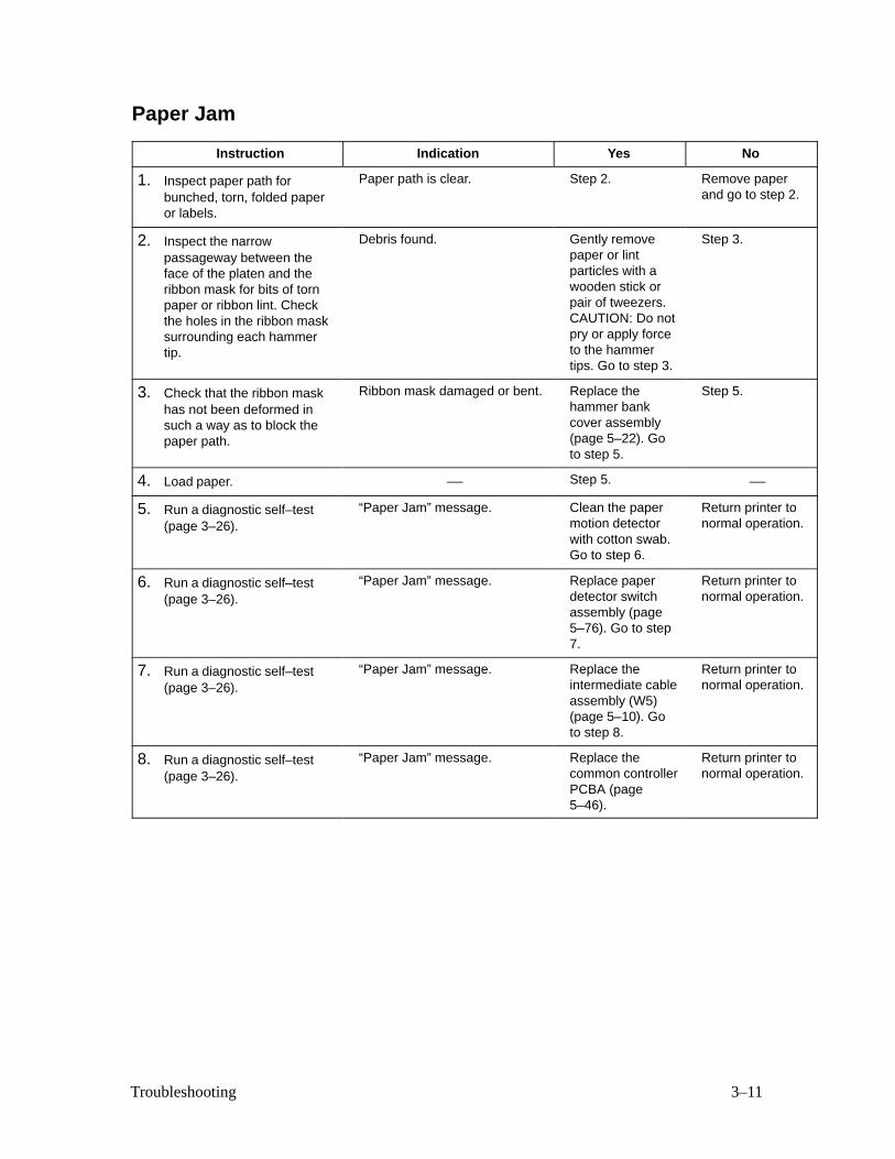
Paper Jam
Instruction Indication Yes No
1. Inspect paper path forbunched, torn, folded paperor labels.
Paper path is clear. Step 2. Remove paperand go to step 2.
2. Inspect the narrowpassageway between theface of the platen and theribbon mask for bits of tornpaper or ribbon lint. Checkthe holes in the ribbon masksurrounding each hammertip.
Debris found. Gently removepaper or lintparticles with awooden stick orpair of tweezers.CAUTION: Do notpry or apply forceto the hammertips. Go to step 3.
Step 3.
3. Check that the ribbon maskhas not been deformed insuch a way as to block thepaper path.
Ribbon mask damaged or bent. Replace thehammer bankcover assembly(page 5–22). Goto step 5.
Step 5.
4. Load paper. — Step 5. —
5. Run a diagnostic self–test(page 3–26).
“Paper Jam” message. Clean the papermotion detectorwith cotton swab.Go to step 6.
Return printer tonormal operation.
6. Run a diagnostic self–test(page 3–26).
“Paper Jam” message. Replace paperdetector switchassembly (page5–76). Go to step7.
Return printer tonormal operation.
7. Run a diagnostic self–test(page 3–26).
“Paper Jam” message. Replace theintermediate cableassembly (W5)(page 5–10). Goto step 8.
Return printer tonormal operation.
8. Run a diagnostic self–test(page 3–26).
“Paper Jam” message. Replace thecommon controllerPCBA (page5–46).
Return printer tonormal operation.
3–12 Troubleshooting
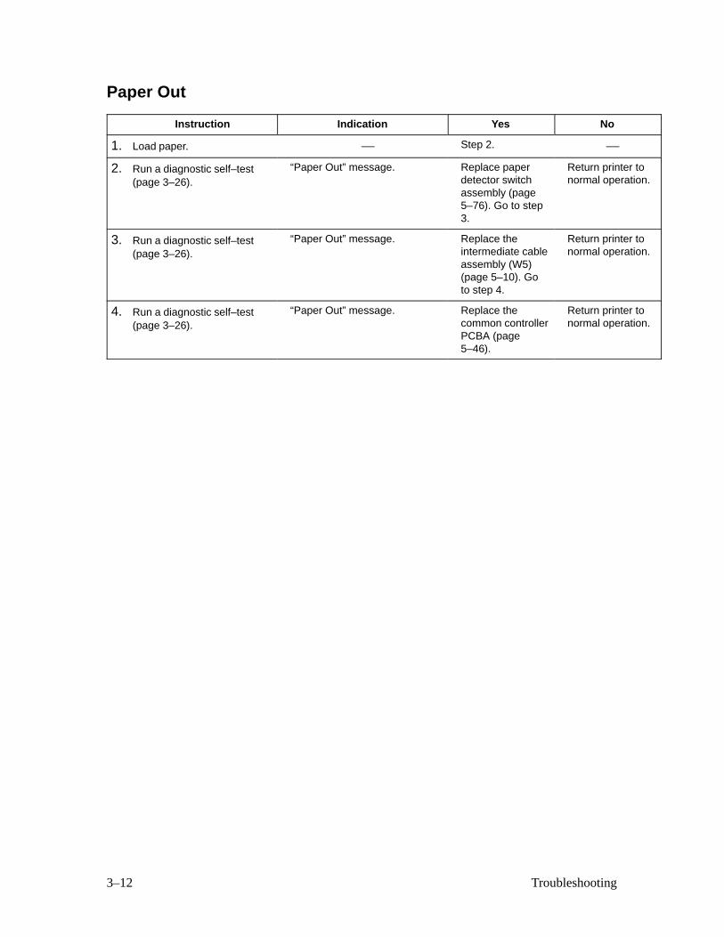
Paper Out
Instruction Indication Yes No
1. Load paper. — Step 2. —
2. Run a diagnostic self–test(page 3–26).
“Paper Out” message. Replace paperdetector switchassembly (page5–76). Go to step3.
Return printer tonormal operation.
3. Run a diagnostic self–test(page 3–26).
“Paper Out” message. Replace theintermediate cableassembly (W5)(page 5–10). Goto step 4.
Return printer tonormal operation.
4. Run a diagnostic self–test(page 3–26).
“Paper Out” message. Replace thecommon controllerPCBA (page5–46).
Return printer tonormal operation.
3–13Troubleshooting
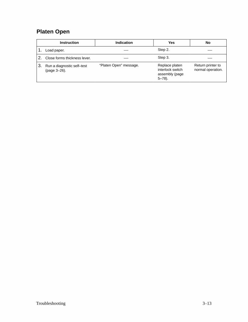
Platen Open
Instruction Indication Yes No
1. Load paper. — Step 2. —
2. Close forms thickness lever. — Step 3. —
3. Run a diagnostic self–test(page 3–26).
“Platen Open” message. Replace plateninterlock switchassembly (page5–78).
Return printer tonormal operation.
3–14 Troubleshooting
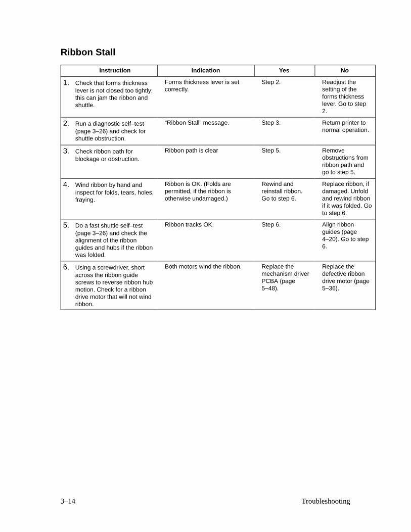
Ribbon Stall
Instruction Indication Yes No
1. Check that forms thicknesslever is not closed too tightly;this can jam the ribbon andshuttle.
Forms thickness lever is setcorrectly.
Step 2. Readjust thesetting of theforms thicknesslever. Go to step2.
2. Run a diagnostic self–test(page 3–26) and check forshuttle obstruction.
“Ribbon Stall” message. Step 3. Return printer tonormal operation.
3. Check ribbon path forblockage or obstruction.
Ribbon path is clear Step 5. Removeobstructions fromribbon path andgo to step 5.
4. Wind ribbon by hand andinspect for folds, tears, holes,fraying.
Ribbon is OK. (Folds arepermitted, if the ribbon isotherwise undamaged.)
Rewind andreinstall ribbon.Go to step 6.
Replace ribbon, ifdamaged. Unfoldand rewind ribbonif it was folded. Goto step 6.
5. Do a fast shuttle self–test(page 3–26) and check thealignment of the ribbonguides and hubs if the ribbonwas folded.
Ribbon tracks OK. Step 6. Align ribbonguides (page4–20). Go to step6.
6. Using a screwdriver, shortacross the ribbon guidescrews to reverse ribbon hubmotion. Check for a ribbondrive motor that will not windribbon.
Both motors wind the ribbon. Replace themechanism driverPCBA (page5–48).
Replace thedefective ribbondrive motor (page5–36).
3–15Troubleshooting
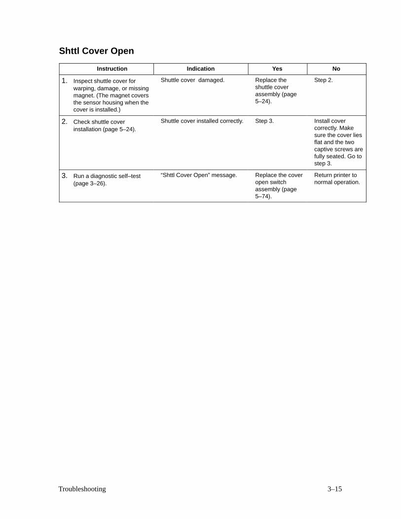
Shttl Cover Open
Instruction Indication Yes No
1. Inspect shuttle cover forwarping, damage, or missingmagnet. (The magnet coversthe sensor housing when thecover is installed.)
Shuttle cover damaged. Replace theshuttle coverassembly (page5–24).
Step 2.
2. Check shuttle coverinstallation (page 5–24).
Shuttle cover installed correctly. Step 3. Install covercorrectly. Makesure the cover liesflat and the twocaptive screws arefully seated. Go tostep 3.
3. Run a diagnostic self–test(page 3–26).
“Shttl Cover Open” message. Replace the coveropen switchassembly (page5–74).
Return printer tonormal operation.
3–16 Troubleshooting
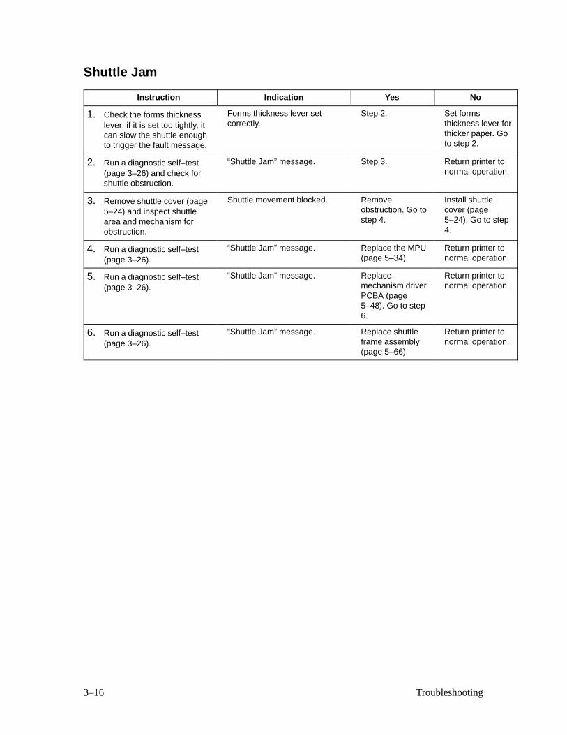
Shuttle Jam
Instruction Indication Yes No
1. Check the forms thicknesslever: if it is set too tightly, itcan slow the shuttle enoughto trigger the fault message.
Forms thickness lever setcorrectly.
Step 2. Set formsthickness lever forthicker paper. Goto step 2.
2. Run a diagnostic self–test(page 3–26) and check forshuttle obstruction.
“Shuttle Jam” message. Step 3. Return printer tonormal operation.
3. Remove shuttle cover (page5–24) and inspect shuttlearea and mechanism forobstruction.
Shuttle movement blocked. Removeobstruction. Go tostep 4.
Install shuttlecover (page5–24). Go to step4.
4. Run a diagnostic self–test(page 3–26).
“Shuttle Jam” message. Replace the MPU(page 5–34).
Return printer tonormal operation.
5. Run a diagnostic self–test(page 3–26).
“Shuttle Jam” message. Replacemechanism driverPCBA (page5–48). Go to step6.
Return printer tonormal operation.
6. Run a diagnostic self–test(page 3–26).
“Shuttle Jam” message. Replace shuttleframe assembly(page 5–66).
Return printer tonormal operation.
3–17Troubleshooting
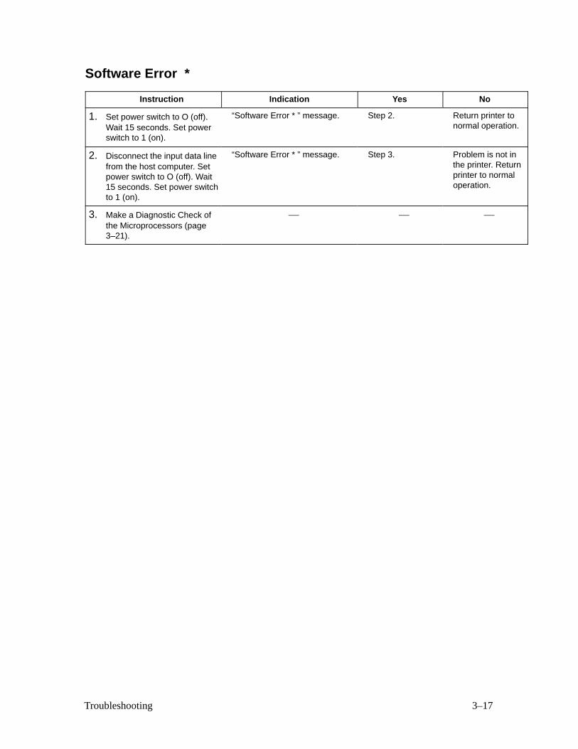
Software Error *
Instruction Indication Yes No
1. Set power switch to O (off).Wait 15 seconds. Set powerswitch to 1 (on).
“Software Error * ” message. Step 2. Return printer tonormal operation.
2. Disconnect the input data linefrom the host computer. Setpower switch to O (off). Wait15 seconds. Set power switchto 1 (on).
“Software Error * ” message. Step 3. Problem is not inthe printer. Returnprinter to normaloperation.
3. Make a Diagnostic Check ofthe Microprocessors (page3–21).
— — —

3–18 Troubleshooting
Symptoms Not Indicated by Fault Messages
Troubleshoot malfunctions not indicated by fault messages using standard
fault–isolation techniques:
1. Debrief the operator for a general description of the problem.
2. Verify the fault by running diagnostic self–tests or replicating conditions
reported by the user.
3. Locate the malfunction using the half–split method:
a. Isolate faults to half the remaining system at a time, until the
final half is a field–replaceable part or assembly.
• Chapter 5 lists all field–replaceable assemblies.
• Troubleshooting aids are listed on the next page.
b. Start at a general level and work down to details.
4. Replace the defective part or assembly.
IMPORTANT
Do NOT attempt field repairs on electronic components or assemblies —replace the entire assembly with an operational spare. Most electronicproblems are corrected by replacing the printed circuit board assembly(PCBA), sensor, or cable that causes the fault indication. The same istrue of failures traced to the hammer bank: replace the entire shuttleframe assembly; it is not field repairable.
5. Test printer operation after every corrective action.
6. Stop troubleshooting and return the printer to normal operation when the
reported symptoms disappear.

3–19Troubleshooting
Troubleshooting Aids
• Printer Confidence Check (page 3–20). This procedure
systematically checks basic printer operations and functions. Use it
to establish basic printer status or for troubleshooting imprecise or
intermittent symptoms.
• Diagnostic Check of Microprocessors (page 3–21). Thisprocedure checks processor operations on the printed circuit board
assemblies (PCBAs).
• Diagnostic Self–Tests (Page 3–26.)
• Hex Code Printout (Page 3–29.)
• Appendix D: Cable Interconnections and Hammer BankWiring Diagram
3–20 Troubleshooting
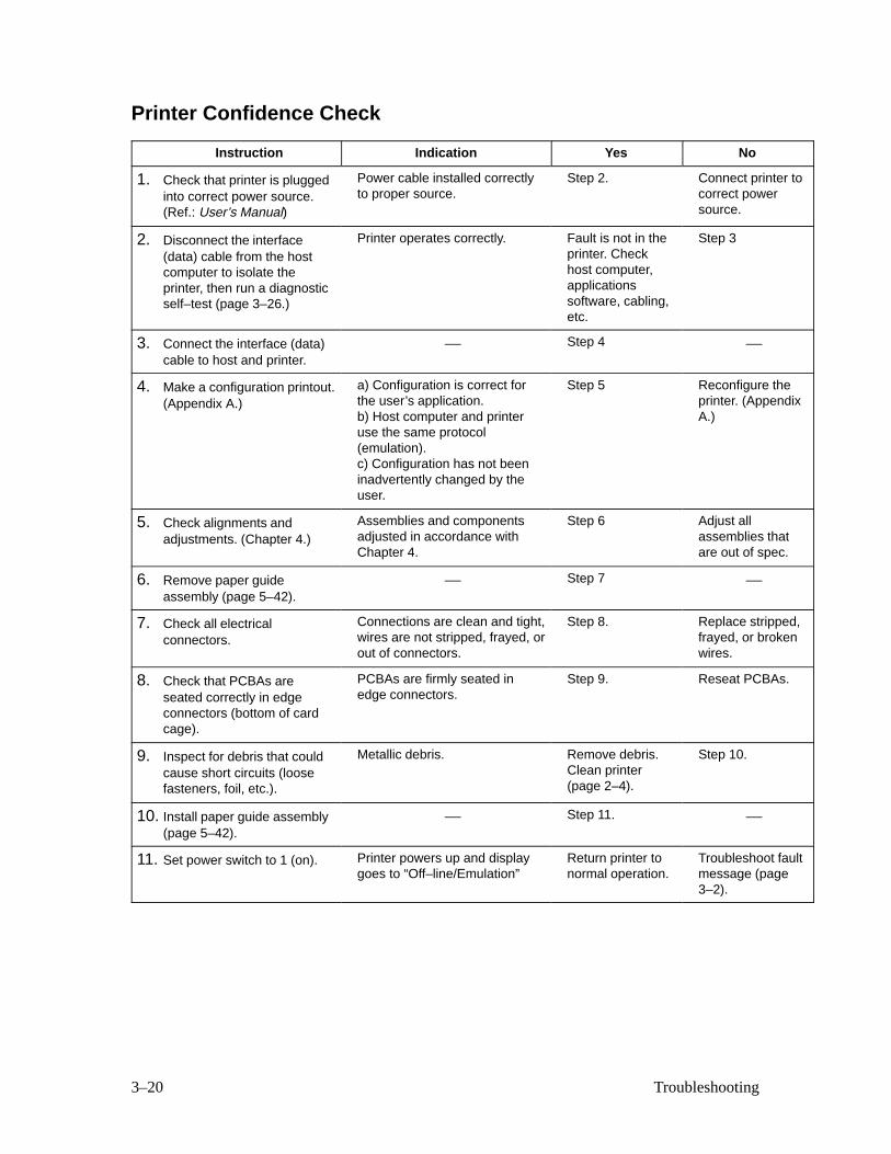
Printer Confidence Check
Instruction Indication Yes No
1. Check that printer is pluggedinto correct power source.(Ref.: User’s Manual)
Power cable installed correctlyto proper source.
Step 2. Connect printer tocorrect powersource.
2. Disconnect the interface(data) cable from the hostcomputer to isolate theprinter, then run a diagnosticself–test (page 3–26.)
Printer operates correctly. Fault is not in theprinter. Checkhost computer,applicationssoftware, cabling,etc.
Step 3
3. Connect the interface (data)cable to host and printer.
— Step 4 —
4. Make a configuration printout.(Appendix A.)
a) Configuration is correct forthe user’s application.b) Host computer and printeruse the same protocol(emulation).c) Configuration has not beeninadvertently changed by theuser.
Step 5 Reconfigure theprinter. (AppendixA.)
5. Check alignments andadjustments. (Chapter 4.)
Assemblies and componentsadjusted in accordance withChapter 4.
Step 6 Adjust allassemblies thatare out of spec.
6. Remove paper guideassembly (page 5–42).
— Step 7 —
7. Check all electricalconnectors.
Connections are clean and tight,wires are not stripped, frayed, orout of connectors.
Step 8. Replace stripped,frayed, or brokenwires.
8. Check that PCBAs areseated correctly in edgeconnectors (bottom of cardcage).
PCBAs are firmly seated inedge connectors.
Step 9. Reseat PCBAs.
9. Inspect for debris that couldcause short circuits (loosefasteners, foil, etc.).
Metallic debris. Remove debris.Clean printer(page 2–4).
Step 10.
10. Install paper guide assembly(page 5–42).
— Step 11. —
11. Set power switch to 1 (on). Printer powers up and displaygoes to “Off–line/Emulation”
Return printer tonormal operation.
Troubleshoot faultmessage (page3–2).

3–21Troubleshooting
Diagnostic Check of Microprocessors
This procedure checks the operation of the microprocessors and IC chips on
the Common Controller (CCB) and Mechanism Driver boards. Do the steps
in the order presented.
1. Set the power switch to O (off).
2. Remove the paper guide assembly (page 5–42).
3. Reseat the CCB and Mech Driver boards in the card cage.
4. Set the power switch to 1 (on). Wait at least 15 seconds; while you are
waiting watch the 68010 LED at location A2 on the CCB (some boards
may be silk–screened as “68000”) and watch the display on the control
panel. (NOTE: IC locations are shown on page 5–52.)
a. When the CCB is operating correctly, the control panel displays
“Diagnostic Tests in Progress,” and the 68010 LED turns on for
1 to15 seconds, then turns off. The 68010 LED turns off after the
68010 successfully tests itself, RAM, 68010 ROM, and
communication with the 64180 CPU. The more RAM or ROM
installed in the printer, the longer the LED is on, but it always
turns on then off when the CCB is functioning correctly. If the
printer turns on normally, the CCB is okay. Install the EMI shield
and return the printer to normal operation.
If the 68010 LED turns on and off as described above, but the
printer does work properly, or fails later, go to step 5.
(“Dynamic RAM Fault” on the display can mean the 64180 has
waited 15–20 seconds without getting its handshake from the
68010. The following substeps use the 68010 LED to fault
isolate this message.)
b. If the 68010 LED never turns on, it means the 68010 did not
execute the first software instruction in its ROM. Go to step 6.
c. If the 68010 LED stays on for 30 seconds but never blinks, it
means RAM and ROM for the 68010 are okay, but the 64180 isnot executing instructions. Go to step 7.
d. If the 68010 LED blinks steadily at 1 blink per second, it means
that the 68010 ROMs are bad. Turn off the printer, remove the

3–22 Troubleshooting
CCB (page 5–46), and check that all ROM chips are inserted in
the correct position and with all pins inserted correctly.
This check will catch out–of–order ROMs and all single and
multiple bit failures of floating–gate EPROMs (the type with the
window, that erase with ultraviolet light).
If a ROM chip was inserted backwards, discard it. Even if it
operates properly, a high current flowed through the
backwards–biased transistors, and its service life is probably
shortened due to thermal damage.
If ROMs appear correctly inserted, they may still be defective.Sometimes bits “fade” to one when internal floating gates
discharge. This can occur from over–voltage programming,
radiation damage, too many EPROM erasures, etc. Install new
program PROMs.
e. If the 68010 LED blinks steadily 5 times per second, it means
CCB RAM has failed. The most common cause of this failure
during maintenance is turning off the printer too briefly for the
64180 to reset. The 64180 shares memory with the 68010, and
writes to RAM if it is not completely reset. Turn the printer off,
wait at least 15 seconds, then recycle power before accepting this
indication of CCB RAM failure.
The RAM chips are at board coordinates N9 and P9. The sockets
at N8 and P8 are normally empty; this will not cause a RAM
failure. Inspect the RAM chips, sockets and traces for shorts or
missing chips. Damaged traces or sockets call for replacement of
the CCB.
A remote possibility is failure of the 64180 in the start–up
handshake or in the code that programs the memory controller.
Try changing the 64180 PROM.
5. The 68010 LED turns on, then off, but the printer doesn’t work. Look at
the control panel display:
a. If the display is blank, or has a single line of black squares across
the top, the connector to the control panel probably needs to be
plugged in or reseated. Turn off the printer, plug in the panel
3–23Troubleshooting
cable to connector J3 on the CCB, and start over at step 1. If the
display is still blank, or has a black line, and the 68010 LED
lights and turns off, the control panel or its cable are defective.
b. If the display reads “Mech Driver Link,” the 8032 at location J12
on the CCB may have failed. Check the 8032 and its PROM at
location J10 for bent pins, misalignment, or backwards insertion.
Also, make sure the clock–test jumper E2 at location J14 is
installed. If everything appears okay, try reseating the PROM at
location J10, the 8032 at J12, the clock jumper at J14, and the
connector at J2—sometimes this message is caused by a failure tocommunicate with the 8032 on the Mech Driver board. If the
problem persists, check the Mech Driver 8032, its clock jumper,
and the PROM. Look for backwards insertion, misalignment,
etc., and try reseating the parts. (NOTE: On some Mech Driver
boards, the 8032 PROM correct orientation may be upside down
in relation to the rest of the board. On these boards, the
silk–screen will show the correct orientation.) Always replace
PROMs and parts that were inserted backwards. If the problem
persists, replace the 8032 PROMs on the CCB and Mech Driver
boards. If the problem persists, replace the interconnect cable
W1. (See Appendix D.)
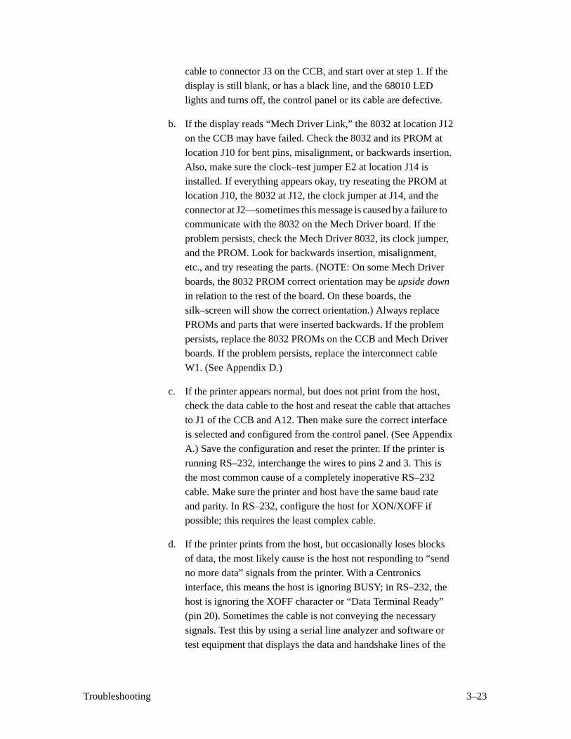
c. If the printer appears normal, but does not print from the host,check the data cable to the host and reseat the cable that attaches
to J1 of the CCB and A12. Then make sure the correct interface
is selected and configured from the control panel. (See Appendix
A.) Save the configuration and reset the printer. If the printer is
running RS–232, interchange the wires to pins 2 and 3. This is
the most common cause of a completely inoperative RS–232
cable. Make sure the printer and host have the same baud rate
and parity. In RS–232, configure the host for XON/XOFF if
possible; this requires the least complex cable.
d. If the printer prints from the host, but occasionally loses blocks
of data, the most likely cause is the host not responding to “send
no more data” signals from the printer. With a Centronicsinterface, this means the host is ignoring BUSY; in RS–232, the
host is ignoring the XOFF character or “Data Terminal Ready”
(pin 20). Sometimes the cable is not conveying the necessary
signals. Test this by using a serial line analyzer and software or
test equipment that displays the data and handshake lines of the

3–24 Troubleshooting
printer. A break–out box works, but will not debug XON/XOFF
or other RS–232 data protocols. If the printer is sending XOFF,
the host may not be receiving it if it requires 1.5 or 2 stop bits.
e. If the printer prints from the host, but occasionally prints double
characters, there is probably a noise problem at the interface or
the host computer is sending an inverted strobe. This problem
can occur on Centronics or Dataproducts interfaces, never on
RS–232. What happens is the strobe signal registers logic 1 more
than once for a certain character. To fix this, change the strobe to
trailing edge or invert the Dataproducts strobe polarity. Alsocheck that the terminating resistors are present at locations C12
and D12 on the CCB. You can correct noise problems by using a
shielded data cable or by changing the terminating resistors. (See
page 5–56.) The standard terminating resistors are optimized for
high speed data transfer for cables between 1 and 5 meters long;
you can change them to be slower and slightly more immune to
noise. Noise is caused by static, floating logic ground, unshielded
cable, changes in ground voltage from nearby equipment, or
capacitively– or magnetically–induced noise. On very long
cables, capacitively–induced noise from the other signals of the
cable (especially Centronics “ACK” or Dataproducts data
request “DRQ”) can cause false strobes. Unshielded and flat
ribbon cables are much more prone to problems due to increased
length. The best solution is to shorten cable, shield it, and reduce
local electromagnetic noise.
f. If the printer prints garbled data or slews uncontrollably, put the
printer into hex dump mode and analyze the binary data. One
cause of garble is the host interface or cable is not transmitting
all the data. When this occurs, the Centronics or Dataproducts
interface receives a 1 on every unconnected data line.
Uncontrolled slewing is often caused by enabling PI (Paper
Instruction) when the host lacks a PI signal. (PI shows as “p” on
the hex dump.) Some DEC RS–232 and Dataproducts interfaces
only send 7 data bits. In this case, the eigth bit will be received as
one. In RS–232, a common cause of garble is to set the interface
to the wrong baud rate or parity. Sometimes the host sends 1.5 or
2 stop bits; in this case, the printer’s “1–stop–bit” setting willaccept both 1.5 and 2 stop bit data. Sometimes the data may
“fade” or “persist” from one character to the next. This reveals a
problem with Centronics or Dataproducts terminating resistors
3–25Troubleshooting
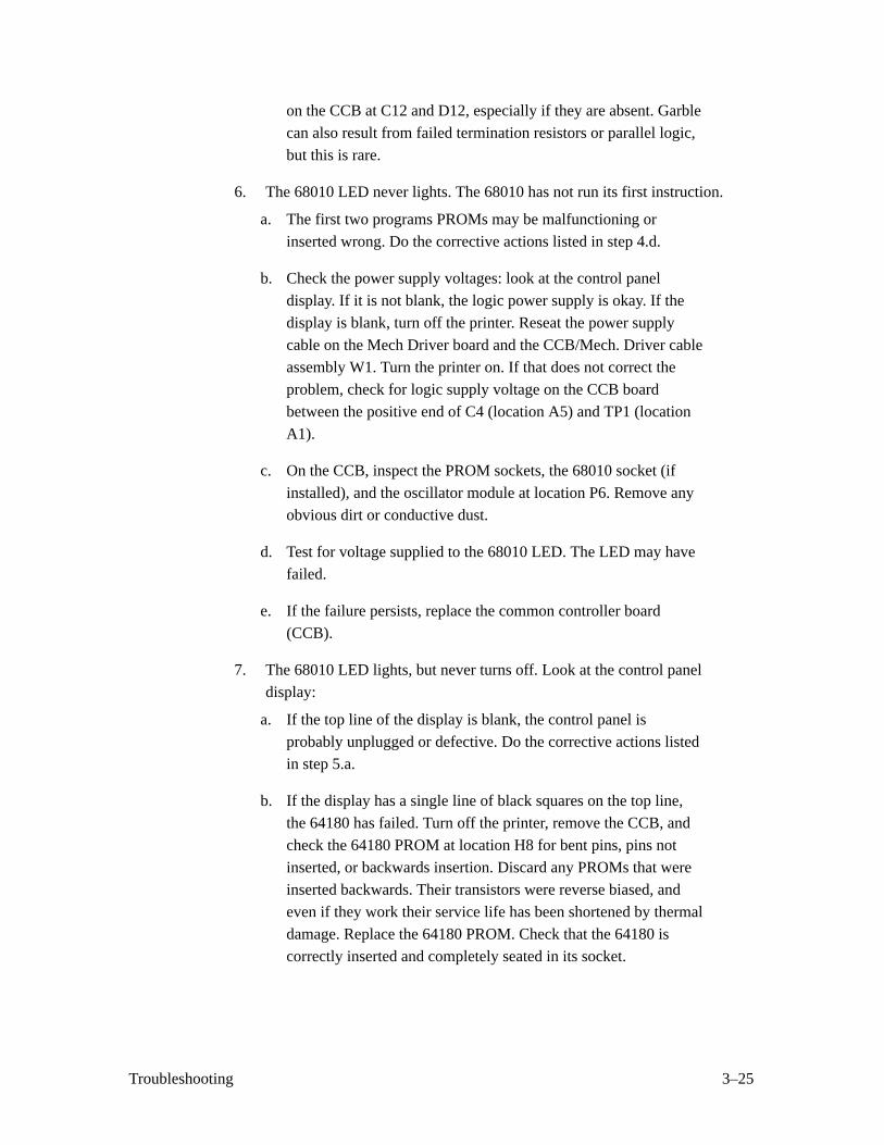
on the CCB at C12 and D12, especially if they are absent. Garble
can also result from failed termination resistors or parallel logic,
but this is rare.
6. The 68010 LED never lights. The 68010 has not run its first instruction.
a. The first two programs PROMs may be malfunctioning or
inserted wrong. Do the corrective actions listed in step 4.d.
b. Check the power supply voltages: look at the control panel
display. If it is not blank, the logic power supply is okay. If the
display is blank, turn off the printer. Reseat the power supply
cable on the Mech Driver board and the CCB/Mech. Driver cable
assembly W1. Turn the printer on. If that does not correct the
problem, check for logic supply voltage on the CCB board
between the positive end of C4 (location A5) and TP1 (location
A1).
c. On the CCB, inspect the PROM sockets, the 68010 socket (if
installed), and the oscillator module at location P6. Remove any
obvious dirt or conductive dust.
d. Test for voltage supplied to the 68010 LED. The LED may have
failed.
e. If the failure persists, replace the common controller board
(CCB).
7. The 68010 LED lights, but never turns off. Look at the control panel
display:
a. If the top line of the display is blank, the control panel is
probably unplugged or defective. Do the corrective actions listedin step 5.a.
b. If the display has a single line of black squares on the top line,
the 64180 has failed. Turn off the printer, remove the CCB, and
check the 64180 PROM at location H8 for bent pins, pins not
inserted, or backwards insertion. Discard any PROMs that were
inserted backwards. Their transistors were reverse biased, and
even if they work their service life has been shortened by thermal
damage. Replace the 64180 PROM. Check that the 64180 is
correctly inserted and completely seated in its socket.
3–26 Troubleshooting
c. If the display reads “Diagnostic Tests in Progress” and 68010
LED has been on for 20 seconds or more but is not blinking, it
means the 64180 cannot communicate with the 8032 on the
Mech Driver board. Turn off the printer, reseat the cable in J2 of
the CCB and on the Mech Driver board. Check the 8032 on the
Mech Driver, its PROM, and its clock jumper (E1–E2) for
correct insertion, bent pins, etc. Reseat the jumper and socketed
parts. If the problem persists, replace the Mech Driver’s PROM
and the CCB/Mech. Driver cable assembly W1.
Diagnostic Self–Tests
Run diagnostic self–tests to check the print quality and operation of the
printer. The self–tests are listed below.
NOTE: Under the description of each diagnostic test is a list of items that
may require field replacement or adjustment if the test produces a
bad print pattern. Items are listed in the order they should be
checked: simplest items first, moving to more complex components.
• ASCII Swirl A sliding alphanumeric pattern useful for identifying
missing or malformed characters, improper vertical alignment, or
vertical compression.
Hammer bank cover
Hammer spring
Shuttle frame assembly
• All Es A pattern of all uppercase letter Es useful for identifying
missing characters, misplaced dots, smeared characters, improper
phasing, or light/dark character variations.
Ribbon
Hammer bank coverMPU sensor
Hammer spring
Hammer coil (shuttle frame assembly)
Splined shaft skew adjustment
3–27Troubleshooting
• Es plus TOF A pattern of all Es followed by a form feed to the
next page top of form, useful for identifying paper motion or feeding
problems.
Hammer bank cover
Power supply PCBA
Mechanism Driver PCBA
Paper motion sensor or cablePaper feed belt or motor
Splined shaft bearings
Tractors or tractor belts
• All Hs A pattern of all uppercase letter Hs useful for detecting
missing characters or dots, smeared characters, or improper phasing.
Ribbon
Hammer bank cover
MPU sensor
Hammer spring
Hammer coil (shuttle frame assembly)
• All Underlines An underline pattern useful for identifying
hammer bank misalignment.
Mechanism Driver PCBA
Hammer bank cover
Hammer tips
Paper feed belt or motor
Splined shaft bearings
Tractor bearings or belts
• All Black All dot positions are printed, creating a solid black band.
Exercises shuttle and hammer bank at maximum capacity.
Mechanism Driver PCBA
Power Supply PCBA
Hammer bank cover
Hammer spring
Hammer coil (shuttle frame assembly)
• Shuttle Slow Verifies proper operation by exercising shuttle
motion at low speed.
• Shuttle Fast Verifies proper operation by exercising shuttle
motion at high speed.
3–28 Troubleshooting
• Phasing A hammer timing parameter that permits you to adjust
the vertical alignment of dots in character printing. (See page 4–4.)
• Test Width Permits you to run tests at all available print widths.
Running the Diagnostic Self–Tests
To run a diagnostic self–test:
1. Press ON LINE to place the printer off–line. “Off–line/Emulation”
displays.
2. Press UP and DOWN simultaneously to unlock the ENTER switch.
3. Raise the printer cover.
4. Press DOWN. “Emulation/LG06” displays.
5. Press NEXT until “Emulation/Self–Test” displays.
6. Press ENTER to select self–test. “Emulation/Self–Test * ” displays.
7. To select one of the tests, press DOWN, then press NEXT or PREV until
the appropriate test displays.
8. Press R/S to begin the selected self–test. Press R/S again to stop the test.
9. Examine the print quality.
10. Press CLEAR to place the printer off–line. The display reads
“Off–line/Emulation”.
11. Press UP and DOWN simultaneously to lock the ENTER switch.
12. Close the printer cover.
13. Press ON LINE to place the printer on–line.
3–29Troubleshooting
Hex Code Printout
Hex dumps list all ASCII character data received from the host computer
with their corresponding two–digit hexadecimal codes. You can use hex
dumps to troubleshoot printer data reception problems.
Printable characters print as the assigned symbol; nonprintable characters are
indicated by a period [.]. The letter [p] before a hex code indicates an active
Paper Instruction (PI) line. A blank space before a hex code indicates an
inactive PI line.
To make a hex printout:
1. Press ON LINE to place the printer off–line. “Off–line/Emulation”
displays.
2. Raise the printer cover.
3. Simultaneously press the UP and DOWN switches to unlock the
ENTER switch. “Unlocked” displays briefly.
4. Press DOWN. “Emulation/LG06” displays.
5. Press NEXT until “Emulation/Hex Dump” displays.
6. Press ENTER. “Emulation/Hex Dump * ” displays.
7. Press on LINE. The display indicates that the printer is on–line in hexdump mode (“On–line/Hex Dump”).
8. Send the data from the host — the data print in hex dump format. (Any
data remaining in the buffer print before the hex code printout starts.)
9. Press on–LINE again to stop the hex dump. The display reads
“Off–line/Emulation”.
10. Press DOWN. “Emulation/LG06” displays.
11. Press ENTER to reselect LG06 emulation. “Emulation/LG06 * ”
displays.
12. Simultaneously press the UP and DOWN switches to lock the ENTER
switch. “Locked” displays briefly.
13. Close the printer cover.
14. Press ON LINE to place the printer on–line.

3–30 Troubleshooting
4–1Adjustment Procedures
4 Adjustment Procedures
Chapter Contents
Preparing the Printer for Maintenance 4–2. . . . . . . . . . . . . . . . . . . . . . . . . . . . . . .
Adjustments 4–2. . . . . . . . . . . . . . . . . . . . . . . . . . . . . . . . . . . . . . . . . . . . . . . . . . . .
Belt, Paper Feed Timing, Adjustment 4–6. . . . . . . . . . . . . . . . . . . . . . . . . . . . .
Belt, Platen Open, Adjustment 4–8. . . . . . . . . . . . . . . . . . . . . . . . . . . . . . . . . .
Hammer Phasing 4–4. . . . . . . . . . . . . . . . . . . . . . . . . . . . . . . . . . . . . . . . . . . .
Paper Drive Motor Pulley Alignment 4–10. . . . . . . . . . . . . . . . . . . . . . . . . . . . .
Paper Scale Alignment 4–2. . . . . . . . . . . . . . . . . . . . . . . . . . . . . . . . . . . . . . . .
Platen Angle Adjustment 4–16. . . . . . . . . . . . . . . . . . . . . . . . . . . . . . . . . . . . . .
Platen Gap Adjustment 4–18. . . . . . . . . . . . . . . . . . . . . . . . . . . . . . . . . . . . . . . .
Platen Open Motor Pulley Alignment 4–12. . . . . . . . . . . . . . . . . . . . . . . . . . . . .
Ribbon Guide Alignment 4–20. . . . . . . . . . . . . . . . . . . . . . . . . . . . . . . . . . . . . .
Splined Shaft Skew Adjustment 4–14. . . . . . . . . . . . . . . . . . . . . . . . . . . . . . . . .
Returning the Printer to Normal Operation 4–22. . . . . . . . . . . . . . . . . . . . . . . . . . . .
4–2 Adjustment Procedures
Preparing the Printer for Maintenance
WARNING
Unless otherwise directed, do adjustment procedures with the printerdisconnected from the power source. Failure to remove power couldresult in injury to personnel or damage to equipment.
The procedures in this chapter are written assuming the printer has been
prepared for maintenance. To prepare the printer for maintenance, do the
following before performing an adjustment or alignment:
1. Set the printer power switch to O (off).
2. Disconnect the power cord from the ac power source.
3. Unload paper.
4. Read through the entire maintenance procedure before you begin
working on the printer.
5. Gather all necessary tools and parts before you begin working on the
printer.
Adjustments
This chapter contains the adjustment procedures done at the field service
maintenance level.
Paper Scale Adjustment (Figure 4–1 )
1. Connect the power cord to the ac power source.
2. Set the printer power switch to 1 (on).
3. Load paper.
4. Open the printer cover.
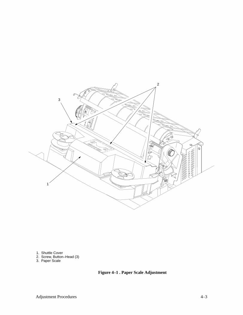
5. Verify that the shuttle cover (1) is properly installed (page 5–24).
6. Loosen the three button–head screws (2). (It may be necessary to
remove the shuttle cover to loosen the button–head screws.)
7. Position the scale (3) so that positions 1 and 132 are lined up with the
first and last characters on a 132 character printout.
8. Tighten the button–head screws (2).
9. Close the printer cover.
4–3Adjustment Procedures
1. Shuttle Cover2. Screw, Button–Head (3)3. Paper Scale
2
3
1
Figure 4–1 . Paper Scale Adjustment
4–4 Adjustment Procedures
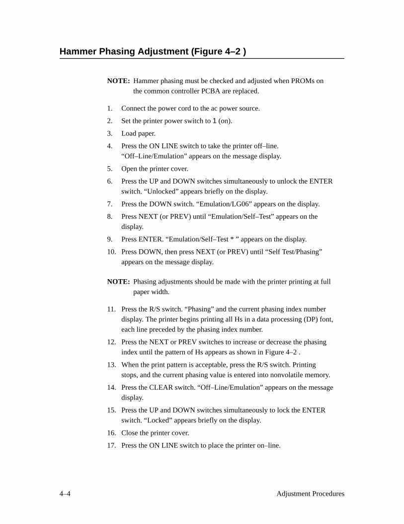
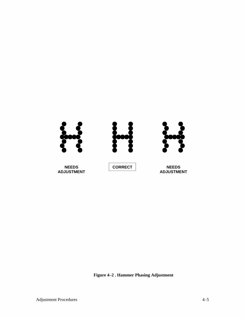
Hammer Phasing Adjustment (Figure 4–2 )
NOTE: Hammer phasing must be checked and adjusted when PROMs on
the common controller PCBA are replaced.
1. Connect the power cord to the ac power source.
2. Set the printer power switch to 1 (on).
3. Load paper.
4. Press the ON LINE switch to take the printer off–line.
“Off–Line/Emulation” appears on the message display.
5. Open the printer cover.
6. Press the UP and DOWN switches simultaneously to unlock the ENTER
switch. “Unlocked” appears briefly on the display.
7. Press the DOWN switch. “Emulation/LG06” appears on the display.
8. Press NEXT (or PREV) until “Emulation/Self–Test” appears on the
display.
9. Press ENTER. “Emulation/Self–Test * ” appears on the display.
10. Press DOWN, then press NEXT (or PREV) until “Self Test/Phasing”
appears on the message display.
NOTE: Phasing adjustments should be made with the printer printing at full
paper width.
11. Press the R/S switch. “Phasing” and the current phasing index number
display. The printer begins printing all Hs in a data processing (DP) font,
each line preceded by the phasing index number.
12. Press the NEXT or PREV switches to increase or decrease the phasing
index until the pattern of Hs appears as shown in Figure 4–2 .
13. When the print pattern is acceptable, press the R/S switch. Printing
stops, and the current phasing value is entered into nonvolatile memory.
14. Press the CLEAR switch. “Off–Line/Emulation” appears on the message
display.
15. Press the UP and DOWN switches simultaneously to lock the ENTER
switch. “Locked” appears briefly on the display.
16. Close the printer cover.
17. Press the ON LINE switch to place the printer on–line.
4–5Adjustment Procedures
CORRECT NEEDSADJUSTMENT
NEEDSADJUSTMENT
Figure 4–2 . Hammer Phasing Adjustment
4–6 Adjustment Procedures
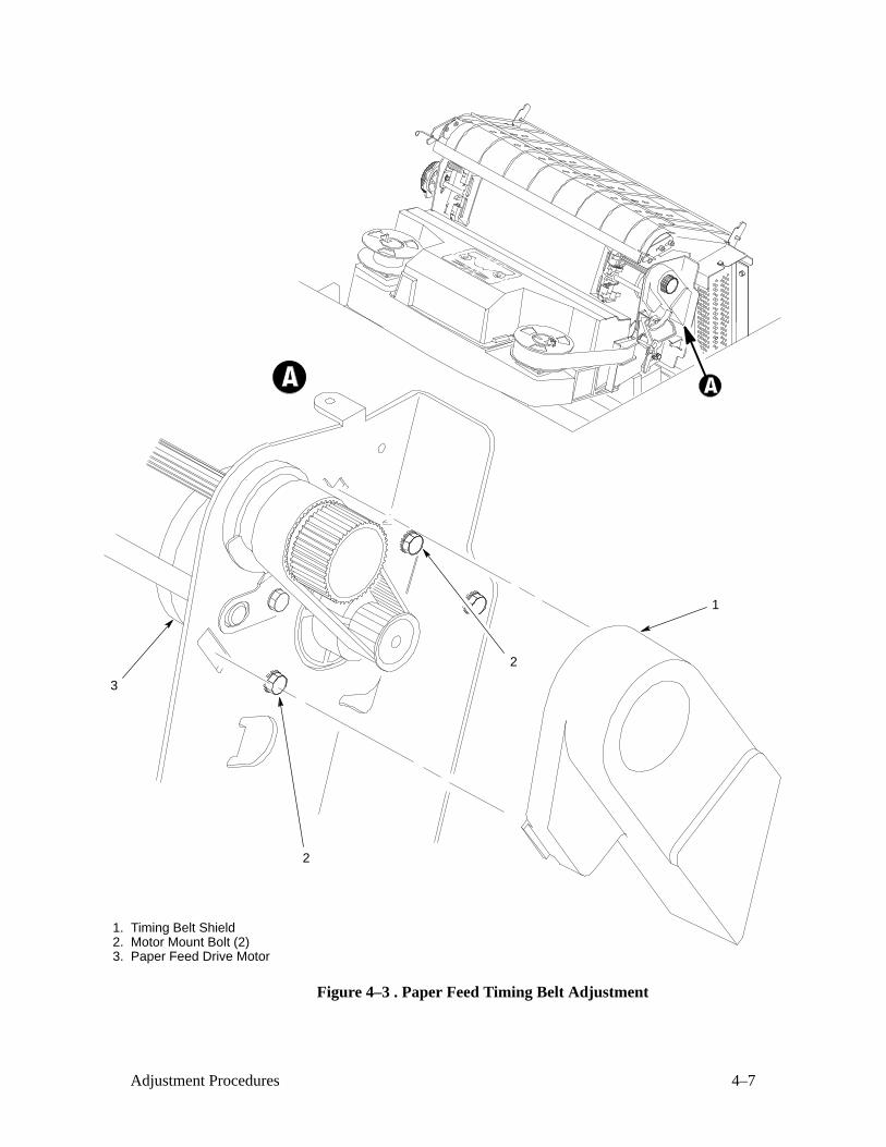
Paper Feed Timing Belt Adjustment (Figure 4–3 )
1. Prepare the printer for maintenance (page 4–2).
2. Open the printer cover.
3. Remove the timing belt cover (1) by squeezing the top and bottom to
release the plastic tabs from the slots in the side plate.
4. Loosen the motor mount bolts (2).
5. Using a force gauge, apply 12 pounds of tension to the paper feed drive
motor (3).
6. Reduce tension to 9 pounds and torque the paper feed motor mount bolts
(2) to 18 ± 1 inch–pounds.
7. Snap the timing belt cover (1) into the slots in the side plate.
8. Return the printer to normal operation (page 4–22).
4–7Adjustment Procedures
1. Timing Belt Shield2. Motor Mount Bolt (2)3. Paper Feed Drive Motor
2
1
3
2
Figure 4–3 . Paper Feed Timing Belt Adjustment
4–8 Adjustment Procedures
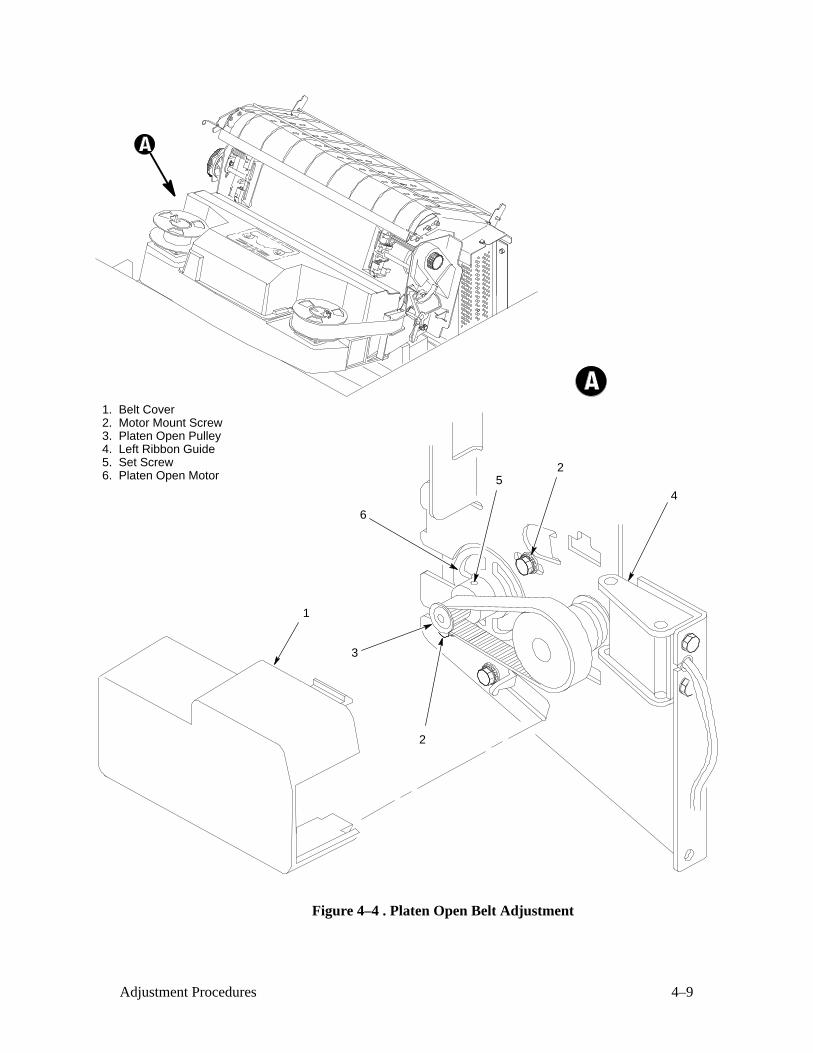
Platen Open Belt Adjustment (Figure 4–4 )
1. Prepare the printer for maintenance (page 4–2).
2. Open the printer cover.
3. Remove the platen open belt cover (1) by squeezing the top and bottom
to release the plastic tabs from the slots in the side plate.
4. Loosen the motor mount screws (2).
5. Close the forms thickness lever all the way.
6. Make sure the collar of the platen open pulley (3) clears the left ribbon
guide (4) with the platen fully closed.
a. If not, rotate the platen open pulley (3) until the collar clears the
left ribbon guide and tighten the set screw (5). Go to step 7.
b. If the collar clears the ribbon guide with the forms thickness
lever closed, go to step 7.
7. Using a force gauge, apply 10 pounds of tension to the platen open
motor (6).
8. Reduce tension to 5 pounds and torque the motor mount screws (2) to
11 ± 1 inch–pounds.
9. Snap the platen open belt cover (1) into the slots in the side plate.
10. Return the printer to normal operation (page 4–22).
4–9Adjustment Procedures
1. Belt Cover2. Motor Mount Screw3. Platen Open Pulley4. Left Ribbon Guide5. Set Screw6. Platen Open Motor
1
2
3
5
6
2
4
Figure 4–4 . Platen Open Belt Adjustment
4–10 Adjustment Procedures
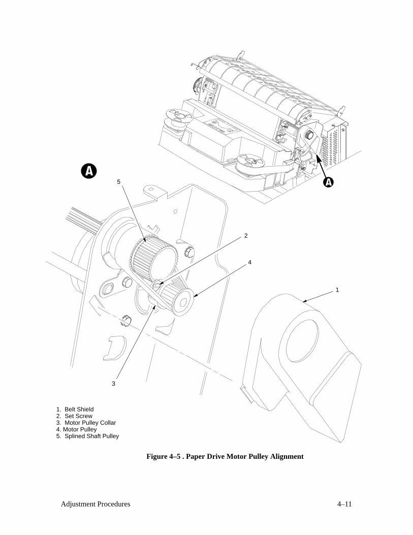
Paper Drive Motor Pulley Alignment (Figure 4–5 )
1. Prepare the printer for maintenance (page 4–2).
2. Open the printer cover.
3. Remove the timing belt cover (1) by squeezing the top and bottom to
release the plastic tabs from the slots in the side plate.
4. Loosen the set screw (2) in the motor pulley collar (3).
5. Align the paper drive motor pulley (4) with the splined shaft pulley (5).
6. Hold the collar (3) flush against the motor pulley (4) and tighten the set
screw (2).
7. Snap the timing belt cover (1) into the slots in the side plate.
8. Return the printer to normal operation (page 4–22).
4–11Adjustment Procedures
1. Belt Shield2. Set Screw3. Motor Pulley Collar4. Motor Pulley5. Splined Shaft Pulley
4
1
2
3
5
Figure 4–5 . Paper Drive Motor Pulley Alignment
4–12 Adjustment Procedures
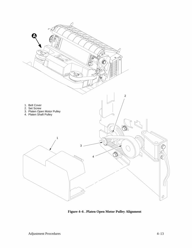
Platen Open Motor Pulley Alignment (Figure 4–6 )
1. Prepare the printer for maintenance (page 4–2).
2. Open the printer cover.
3. Remove the platen open belt cover (1) by squeezing the top and bottom
to release the plastic tabs from the slots in the side plate.
4. Loosen the set screw (2) in the motor pulley collar.
5. Align the platen open motor pulley (3) with the platen shaft pulley (4)
and tighten the set screw (2).
6. Snap the platen open belt cover (1) into the slots in the side plate.
7. Return the printer to normal operation (page 4–22).
4–13Adjustment Procedures
1. Belt Cover2. Set Screw3. Platen Open Motor Pulley4. Platen Shaft Pulley
1
2
3
4
Figure 4–6 . Platen Open Motor Pulley Alignment
4–14 Adjustment Procedures
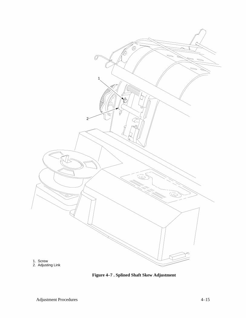
Splined Shaft Skew Adjustment (Figure 4–7 )
If lines of print are not parallel with the edge perforations on the paper,
perform the following adjustment.
1. Prepare the printer for maintenance (page 4–2).
2. Loosen the screw (1) securing the adjusting link (2).
3. Adjust the link (2) to obtain print parallel with paper perforations.
Tighten the screw (1).
4. Return the printer to normal operation (page 4–22).
4–15Adjustment Procedures
1. Screw 2. Adjusting Link
1
2
Figure 4–7 . Splined Shaft Skew Adjustment
4–16 Adjustment Procedures
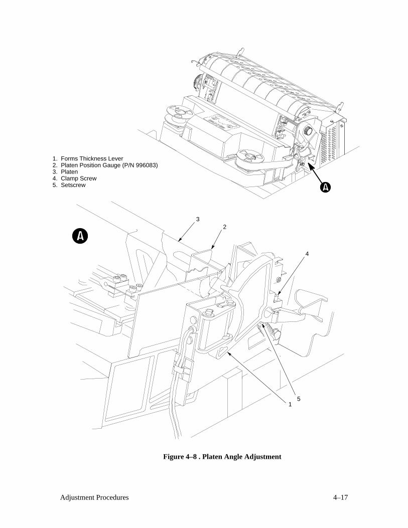
Platen Angle Adjustment (Figure 4–8 )
1. Prepare the printer for maintenance (page 4–2).
2. Remove the shuttle cover (page 5–24).
3. Close the forms thickness lever (1) all the way.
4. Install the platen position gauge (P/N 996083) (2) and check the angle
of the platen (3).
c. If the angle is correct, no adjustment is necessary. Go to step 8.
d. If the angle is incorrect, loosen the clamp screw (4) and set screw
(5).
5. Apply primer and loctite to the mating surfaces of the forms thickness
lever (1) and platen shaft.
6. Position the platen (3) at the correct angle.
7. Slide the platen (3) to the right and the forms thickness lever (1) to the
left to remove end play. Ensure that the forms thickness lever is fully
closed. Tighten the clamp screw (4), then tighten the setscrew (5).
8. Remove the platen position gauge (P/N 996083) (2).
9. Install the shuttle cover (page 5–24).
10. Return the printer to normal operation (page 4–22).
4–17Adjustment Procedures
1. Forms Thickness Lever2. Platen Position Gauge (P/N 996083)3. Platen4. Clamp Screw5. Setscrew
2
5
4
1
3
Figure 4–8 . Platen Angle Adjustment
4–18 Adjustment Procedures
Platen Gap Adjustment (Figure 4–9 )
1. Prepare the printer for maintenance (page 4–2).
2. Open the printer cover.
3. Remove the shuttle cover assembly (page 5–24).
4. Remove the ribbon.
5. Raise the forms thickness lever (1) to the fully open position.
CAUTION
Do not force the platen against the feeler gauge. Damage to the printerwill result.
6. Insert a 0.010 inch flat feeler gauge (2) straight down between the platen
(3) and ribbon mask (4), within four hammer positions of the end of the
hammer bank.
7. Gently close the forms thickness lever (1) until the hammer tips and
platen contact the feeler gauge. With the forms thickness lever closed all
the way, the feeler gauge should contact both the tips and the platen and
move with light friction. Shift the gauge slightly to verify.
8. Adjust the gap as required by manipulating the set screw (5) located at
each end of the platen (3). Check the gap at both ends of the platen after
each adjustment of a set screw.
9. Repeat steps 4 through 7 at the other end of the hammer bank.
10. When the platen gap is correct at both ends of the platen, install the
ribbon.
11. Install the shuttle cover assembly (page 5–24).
12. Adjust the platen open belt (page 4–8).
13. Return the printer to normal operation (page 4–22).
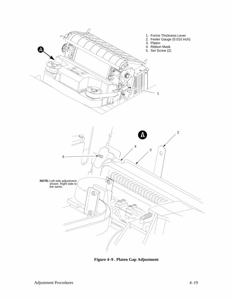
4–19Adjustment Procedures
1. Forms Thickness Lever2. Feeler Gauge (0.010 inch)3. Platen4. Ribbon Mask5. Set Screw (2)
34
2
NOTE: Left side adjustmentshown. Right side isthe same.
5
1
Figure 4–9 . Platen Gap Adjustment
4–20 Adjustment Procedures
Ribbon Guide Alignment (Figure 4–10 )
1. Open the printer cover.
2. Load paper and install the ribbon. The ribbon should have a full spool
on the right hub (1).
3. Run a shuttle and ribbon diagnostic self–test (page 3–26).
4. Momentarily short between the left ribbon guide skid screws (2) to
assure right to left motion of the ribbon.
5. Observe how the ribbon (3) is passing around the left ribbon guide (4).
It should be centered.
6. If the ribbon is not centered, loosen the retaining screws (5) just enough
so that the ribbon guide (4) can be moved to new positions, but remains
in place once moved.
7. Reposition the ribbon guide (4) as necessary to center the ribbon (3).
8. Observe how the ribbon (3) is winding on the left spool (6). Reposition
the ribbon guide (4) as necessary to allow the ribbon to wind up without
interference.
9. Tighten the screws (5).
10. Allow most of the ribbon to accumulate on the left spool (6). Repeat
steps 3 through 9 for the right ribbon guide (7).
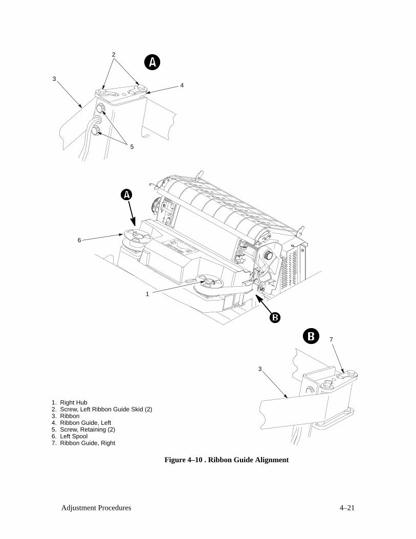
4–21Adjustment Procedures
1. Right Hub2. Screw, Left Ribbon Guide Skid (2)3. Ribbon4. Ribbon Guide, Left5. Screw, Retaining (2)6. Left Spool7. Ribbon Guide, Right
6
2
3
34
5
7
1
Figure 4–10 . Ribbon Guide Alignment
4–22 Adjustment Procedures
Returning the Printer to Normal Operation
1. Load paper.
2. Install the ribbon.
3. Close floor cabinet doors and the printer cover.
4. Connect the ac power cord to the power source and the printer.
5. Set the power switch to 1 (on).
6. Test printer operation by selecting and running one of the diagnostic
self–tests (page 3–26).
5–1Replacement Procedures
5 Replacement Procedures
Chapter Contents
Replacement Procedures 5–3. . . . . . . . . . . . . . . . . . . . . . . . . . . . . . . . . . . . . . . . . .
Preparing the Printer for Maintenance 5–3. . . . . . . . . . . . . . . . . . . . . . . . . . . . . . .
Belt, Paper Feed Timing 5–4. . . . . . . . . . . . . . . . . . . . . . . . . . . . . . . . . . . . . . .
Belt, Platen Open 5–6. . . . . . . . . . . . . . . . . . . . . . . . . . . . . . . . . . . . . . . . . . . .
Cable Assembly W4, Hammer Bank 5–8. . . . . . . . . . . . . . . . . . . . . . . . . . . . .
Cable Assembly W5, Intermediate 5–10. . . . . . . . . . . . . . . . . . . . . . . . . . . . . . .
Cable Assembly, Multi I/O 5–14. . . . . . . . . . . . . . . . . . . . . . . . . . . . . . . . . . . . .
Circuit Breaker 5–18. . . . . . . . . . . . . . . . . . . . . . . . . . . . . . . . . . . . . . . . . . . . . .
Control Panel Assembly 5–20. . . . . . . . . . . . . . . . . . . . . . . . . . . . . . . . . . . . . . .
Cover Assembly, Hammer Bank 5–22. . . . . . . . . . . . . . . . . . . . . . . . . . . . . . . . .
Cover Assembly, Shuttle 5–24. . . . . . . . . . . . . . . . . . . . . . . . . . . . . . . . . . . . . . .
Fan Assembly, Card Cage 5–26. . . . . . . . . . . . . . . . . . . . . . . . . . . . . . . . . . . . . .
Fan Assembly, Cabinet Exhaust 5–28. . . . . . . . . . . . . . . . . . . . . . . . . . . . . . . . .
Fan Assembly, Hammer Bank 5–30. . . . . . . . . . . . . . . . . . . . . . . . . . . . . . . . . .
Hammer Spring Assembly 5–32. . . . . . . . . . . . . . . . . . . . . . . . . . . . . . . . . . . . .
Magnetic Pick–up (MPU) Assembly 5–34. . . . . . . . . . . . . . . . . . . . . . . . . . . . .
Motor Assembly, Ribbon Drive 5–36. . . . . . . . . . . . . . . . . . . . . . . . . . . . . . . . .
Motor Assembly, Paper Feed 5–38. . . . . . . . . . . . . . . . . . . . . . . . . . . . . . . . . . .
Motor Assembly, Platen Open 5–40. . . . . . . . . . . . . . . . . . . . . . . . . . . . . . . . . .
Paper Guide Assembly 5–42. . . . . . . . . . . . . . . . . . . . . . . . . . . . . . . . . . . . . . . .
Paper Ironer 5–44. . . . . . . . . . . . . . . . . . . . . . . . . . . . . . . . . . . . . . . . . . . . . . . . .
PCBA, Common Controller 5–46. . . . . . . . . . . . . . . . . . . . . . . . . . . . . . . . . . . .
5–2 Replacement Procedures
PCBA, Mechanism Driver 5–48. . . . . . . . . . . . . . . . . . . . . . . . . . . . . . . . . . . . .
PCBA, Power Supply 5–50. . . . . . . . . . . . . . . . . . . . . . . . . . . . . . . . . . . . . . . . .
PROMs, Chips, and ICs on the CCB 5–52. . . . . . . . . . . . . . . . . . . . . . . . . . . . .
PROMs, Chips, and ICs on the Mechanism Driver 5–54. . . . . . . . . . . . . . . . . .
Resistors, Terminating 5–56. . . . . . . . . . . . . . . . . . . . . . . . . . . . . . . . . . . . . . . .
Ribbon Hub 5–58. . . . . . . . . . . . . . . . . . . . . . . . . . . . . . . . . . . . . . . . . . . . . . . . .
Ribbon Guide Assembly (L/R) 5–60. . . . . . . . . . . . . . . . . . . . . . . . . . . . . . . . . .
Shaft, Splined 5–62. . . . . . . . . . . . . . . . . . . . . . . . . . . . . . . . . . . . . . . . . . . . . . .
Shaft, Support 5–64. . . . . . . . . . . . . . . . . . . . . . . . . . . . . . . . . . . . . . . . . . . . . . .
Shuttle Frame Assembly 5–66. . . . . . . . . . . . . . . . . . . . . . . . . . . . . . . . . . . . . . .
Spring Assembly, Gas 5–70. . . . . . . . . . . . . . . . . . . . . . . . . . . . . . . . . . . . . . . . .
Spring, Extension 5–72. . . . . . . . . . . . . . . . . . . . . . . . . . . . . . . . . . . . . . . . . . . .
Switch Assembly, Cover Open 5–74. . . . . . . . . . . . . . . . . . . . . . . . . . . . . . . . . .
Switch Assembly, Paper Detector 5–76. . . . . . . . . . . . . . . . . . . . . . . . . . . . . . . .
Switch Assembly, Platen Interlock 5–78. . . . . . . . . . . . . . . . . . . . . . . . . . . . . . .
Tractor (L/R) 5–80. . . . . . . . . . . . . . . . . . . . . . . . . . . . . . . . . . . . . . . . . . . . . . . .
Returning the Printer to Normal Operation 5–80. . . . . . . . . . . . . . . . . . . . . . . . . . . .
5–3Replacement Procedures
Replacement Procedures
CAUTION
The components specified in this chapter are replaced in the field, butmust be repaired at the factory. Do not attempt field repair of theseitems.
This chapter contains illustrated removal/installation procedures for
components replaceable at the field service level of maintenance. The page
locations of all removal/installation tasks are listed on pages 5–1 and 5–2.
Part Numbers
Part numbers for assemblies on the manufacturer’s recommended spares list
are next to the name of the assembly on the removal/installation illustration.
(Procedures for gaining access to other assemblies do not include assembly
part numbers.) To order electronic parts, call 1–800–234–1998.
Preparing the Printer for Maintenance
Replacement procedures in this chapter are written assuming the printer has
been prepared for maintenance.
To prepare the printer for maintenance, do the following before performing a
replacement task:
1. Set the printer power switch to O (off). (If power must be applied as part
of a maintenance procedure, you will be instructed to do so in the
procedure.)
WARNING
Unless otherwise specified, perform all replacement procedures with theprinter disconnected from the power source. Failure to remove powercould result in injury to persons or damage to equipment.
2. Disconnect the power cord from the ac power source.
3. Unload paper.
4. Read the entire maintenance procedure before you begin working on the
printer.
5. Gather the necessary replacement parts before you begin working on the
printer.
5–4 Replacement Procedures
Belt, Paper Feed Timing (Figure 5–1 )
Removal
1. Prepare the printer for maintenance (page 5–3).
2. Open the printer cover.
3. Remove the timing belt cover (1) by squeezing the top and bottom to
release the plastic tabs from the slots in the side plate.
4. Loosen the paper feed motor mount bolts (2).
5. Remove the paper feed timing belt (3) by working the side of the belt
onto the lip of the motor pulley (4) and rotating the pulleys until the belt
rolls off.
Installation
1. Install the paper feed timing belt (3) over the splined shaft pulley (5) and
the lip of the motor pulley (4) and rotate the pulleys until the belt rolls
onto the motor pulley.
2. Using a force gauge, apply 12 pounds of tension to the paper feed drive
motor (6).
3. Reduce tension to 9 pounds and torque the paper feed motor mount bolts
(2) to 18 ± 1 inch–pounds.
4. Snap the timing belt cover (1) into the slots in the side plate.
5. Return the printer to normal operation (page 5–80).
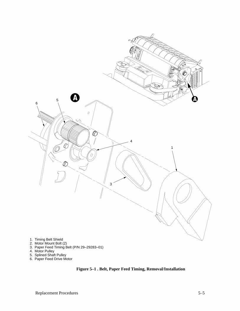
5–5Replacement Procedures
1. Timing Belt Shield2. Motor Mount Bolt (2)3. Paper Feed Timing Belt (P/N 29–29283–01)4. Motor Pulley5. Splined Shaft Pulley6. Paper Feed Drive Motor
5
4
1
3
6
Figure 5–1 . Belt, Paper Feed Timing, Removal/Installation
5–6 Replacement Procedures
Belt, Platen Open (Figure 5–2 )
Removal
1. Prepare the printer for maintenance (page 5–3).
2. Open the printer cover.
3. Remove the platen open belt cover (1) by squeezing the top and bottom
to release the plastic tabs from the slots in the side plate.
4. Loosen the motor mount screws (2).
5. Apply tension to the motor shaft to loosen the platen open belt (3).
6. Remove the platen open belt (3) from the motor pulley (4) and platen
pulley (5).
Installation
1. Slide the platen open belt (3) over the motor pulley (4) and platen
pulley (5).
2. Close the forms thickness lever all the way.
3. Make sure the collar of the platen pulley (5) clears the left ribbon guide
with the platen fully closed.
a. If not, rotate the platen pulley (5) until the collar clears the left
ribbon guide and tighten the set screw (6). Go to step 4.
b. If the collar clears the ribbon guide with the forms thickness
lever closed, go to step 4.
4. Using a force gauge, apply 10 pounds of tension to the platen open
motor.
5. Reduce tension to 5 pounds and torque the motor mount screws (2) to
11 ± 1 inch–pounds.
6. Snap the platen open belt cover (1) into the slots in the side plate.
7. Return the printer to normal operation (page ).
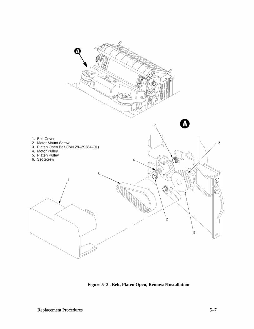
5–7Replacement Procedures
1. Belt Cover2. Motor Mount Screw3. Platen Open Belt (P/N 29–29284–01)4. Motor Pulley5. Platen Pulley6. Set Screw
1
6
5
2
2
4
3
Figure 5–2 . Belt, Platen Open, Removal/Installation

5–8 Replacement Procedures
Cable Assembly, Hammer Bank (Figure 5–3 )
Removal
NOTE: This procedure removes the left hammer bank cable assembly. Theprocedure for removing the right cable assembly is the same.
1. Prepare the printer for maintenance (page 5–3).
2. Open the printer cover.
3. Remove the paper guide assembly (page ).
4. Remove the common controller PCBA (page 5–46).
5. Remove the mechanism driver PCBA (page 5–48).
6. Remove the power supply PCBA (page 5–50).
7. Remove two screws (1) securing the connector (2) to the bottom of thecard cage.
8. Remove two screws (3) securing the connector (4) to the base casting.
9. Note the location and number of tie wraps, then remove them.
10. Feed the hammer bank cable assembly (5) down through the basecasting, then out of the card cage.
Installation
NOTE: This procedure installs the left hammer bank cable assembly. Theprocedure for installing the right cable assembly is the same.
1. Feed the hammer bank cable assembly (5) down through card cage,around the printer, then up through the base casting.
2. Install two screws (3) securing the connector (4) to the base casting.
3. Install two screws (1) securing the connector (2) to the bottom of thecard cage.
4. Install tie wraps to join left and right hammer bank cable assemblies.
5. Install the power supply PCBA (page 5–50).
6. Install the mechanism driver PCBA (page 5–48).
7. Install the common controller PCBA (page 5–46).
8. Install the paper guide assembly (page 5–42).
9. Return the printer to normal operation (page 5–80).
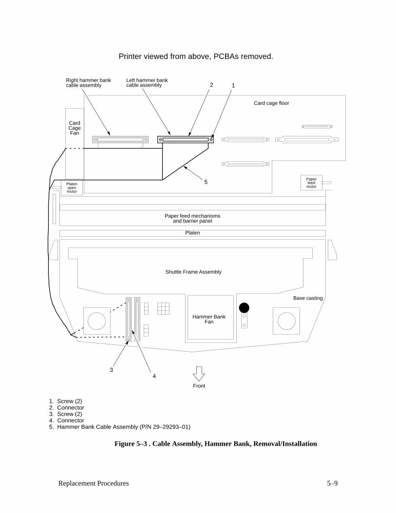
5–9Replacement Procedures
Card cage floor
Front
Printer viewed from above, PCBAs removed.
Shuttle Frame Assembly
Hammer BankFan
CardCageFan
Paper feed mechanismsand barrier panel
Platen
Base casting
Platenopenmotor
Paperfeed
motor
1. Screw (2) 2. Connector3. Screw (2) 4. Connector5. Hammer Bank Cable Assembly (P/N 29–29293–01)
2 1Right hammer bank
cable assemblyLeft hammer bank
cable assembly
34
5
Figure 5–3 . Cable Assembly, Hammer Bank, Removal/Installation
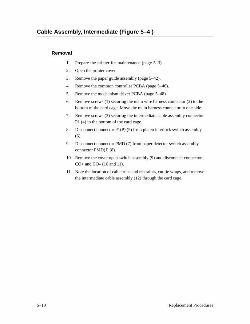
5–10 Replacement Procedures
Cable Assembly, Intermediate (Figure 5–4 )
Removal
1. Prepare the printer for maintenance (page 5–3).
2. Open the printer cover.
3. Remove the paper guide assembly (page 5–42).
4. Remove the common controller PCBA (page 5–46).
5. Remove the mechanism driver PCBA (page 5–48).
6. Remove screws (1) securing the main wire harness connector (2) to the
bottom of the card cage. Move the main harness connector to one side.
7. Remove screws (3) securing the intermediate cable assembly connectorP1 (4) to the bottom of the card cage.
8. Disconnect connector P1(P) (5) from platen interlock switch assembly
(6).
9. Disconnect connector PMD (7) from paper detector switch assembly
connector PMD(J) (8).
10. Remove the cover open switch assembly (9) and disconnect connectors
CO+ and CO– (10 and 11).
11. Note the location of cable runs and restraints, cut tie wraps, and remove
the intermediate cable assembly (12) through the card cage.
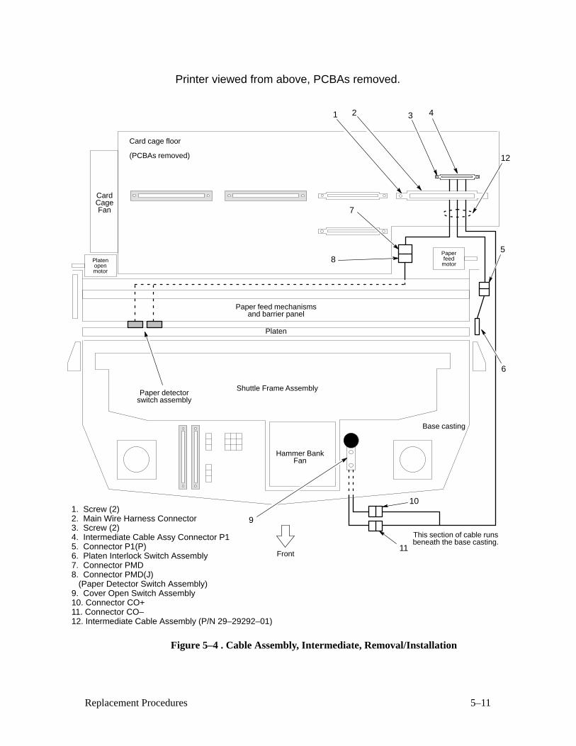
5–11Replacement Procedures
Card cage floor
Front
Shuttle Frame Assembly
Hammer BankFan
CardCageFan
Paper feed mechanismsand barrier panel
Platen
Base casting
Platenopenmotor
Paperfeed
motor
(PCBAs removed)
1. Screw (2) 2. Main Wire Harness Connector3. Screw (2) 4. Intermediate Cable Assy Connector P15. Connector P1(P)6. Platen Interlock Switch Assembly7. Connector PMD8. Connector PMD(J) (Paper Detector Switch Assembly)9. Cover Open Switch Assembly10. Connector CO+11. Connector CO–12. Intermediate Cable Assembly (P/N 29–29292–01)
1 2 3 4
5
6
12
7
8
10
11
9
This section of cable runsbeneath the base casting.
Paper detectorswitch assembly
Printer viewed from above, PCBAs removed.
Figure 5–4 . Cable Assembly, Intermediate, Removal/Installation
5–12 Replacement Procedures
Installation
1. Feed the intermediate cable assembly (12) through the card cage
opening and install tie wraps and cable restraints.
2. Connect connectors CO+ and CO– (10 and 11) and install the cover
open switch assembly (9).
3. Connect connector PMD (7) to paper detector switch assembly
connector PMD(J) (8).
4. Connect connector P1(P) (5) to the platen interlock switch assembly (6).
5. Install the screws (3) securing the intermediate cable assembly
connector P1 (4) to the bottom of the card cage.
6. Move the main harness connector (2) back into position and install the
screws (1) securing the connector to the bottom of the card cage.
7. Install the mechanism driver PCBA (page 5–48).
8. Install the common controller PCBA (page 5–46).
9. Install the paper guide assembly (page 5–42).
10. Return the printer to normal operation (page 5–80).

5–13Replacement Procedures
Card cage floor
Front
Shuttle Frame Assembly
Hammer BankFan
CardCageFan
Paper feed mechanismsand barrier panel
Platen
Base casting
Platenopenmotor
Paperfeed
motor
(PCBAs removed)
1. Screw (2) 2. Main Wire Harness Connector3. Screw (2) 4. Intermediate Cable Assy Connector P15. Connector P1(P)6. Platen Interlock Switch Assembly7. Connector PMD8. Connector PMD(J) (Paper Detector Switch Assembly)9. Cover Open Switch Assembly10. Connector CO+11. Connector CO–12. Intermediate Cable Assembly (P/N 29–29292–01)
1 2 3 4
5
6
12
7
8
10
11
9
This section of cable runsbeneath the base casting.
Paper detectorswitch assembly
Printer viewed from above, PCBAs removed.
Figure 5–4. Cable Assembly, Intermediate, Removal/Installation
5–14 Replacement Procedures
Cable Assembly, Multi I/O (Figure 5–5 )
Removal
1. Prepare the printer for maintenance (page 5–3).
2. Open the printer cover.
3. Remove the paper guide assembly (page 5–42).
4. Open the rear cabinet door.
5. Remove six screws (1) and move the fan duct (2) aside.
6. Open the ribbon cable restraints (3) on the upper rear and upper right
walls of the cabinet.
7. Open the latches (4) and disconnect the multi I/O ribbon cable connector(5) from connector J1 (6) on the common controller PCBA.
8. Release the multi I/O ribbon cable from the holders on the rear wall of
the card cage.
9. Feed the multi I/O ribbon cable through the card cage and down into the
cabinet.
10. Remove four screws (7) securing the multi I/O cable assembly mounting
plate (8).
11. Remove the multi I/O cable assembly (9).

5–15Replacement Procedures
1. Screw (6)2. Fan Duct3. Ribbon Cable Restraints4. Latch (2)5. Ribbon Cable Connector6. Common Controller Connector J17. Screw (4)8. Mounting Plate9. Multi I/O Cable Assembly (P/N 29–29291–01)
1
3
2
5
4
6
7
8
9
Figure 5–5. Cable Assembly, Multi I/O, Removal/Installation
5–16 Replacement Procedures
Installation
1. Feed the multi I/O ribbon cable from the lower cabinet up into the
opening at the right rear of the card cage. Route the ribbon cable
outboard of the right gas spring assembly (the strut that holds the printercover open).
2. Install four screws (7) securing the multi I/O cable assembly mounting
plate (8).
3. Connect the multi I/O ribbon cable connector (5) to connector J1 (6) on
the common controller PCBA and close the latches (4).
4. Latch the multi I/O ribbon cable into the cable restraints (3) located on
the upper rear and upper right cabinet walls.
5. Engage the multi I/O ribbon cable in the holders on the rear wall of the
card cage.
6. Move the fan duct (2) into position and install the six screws (1).
7. Close the rear cabinet door.
8. Install the paper guide assembly (page 5–42).
9. Return the printer to normal operation (page 5–80).
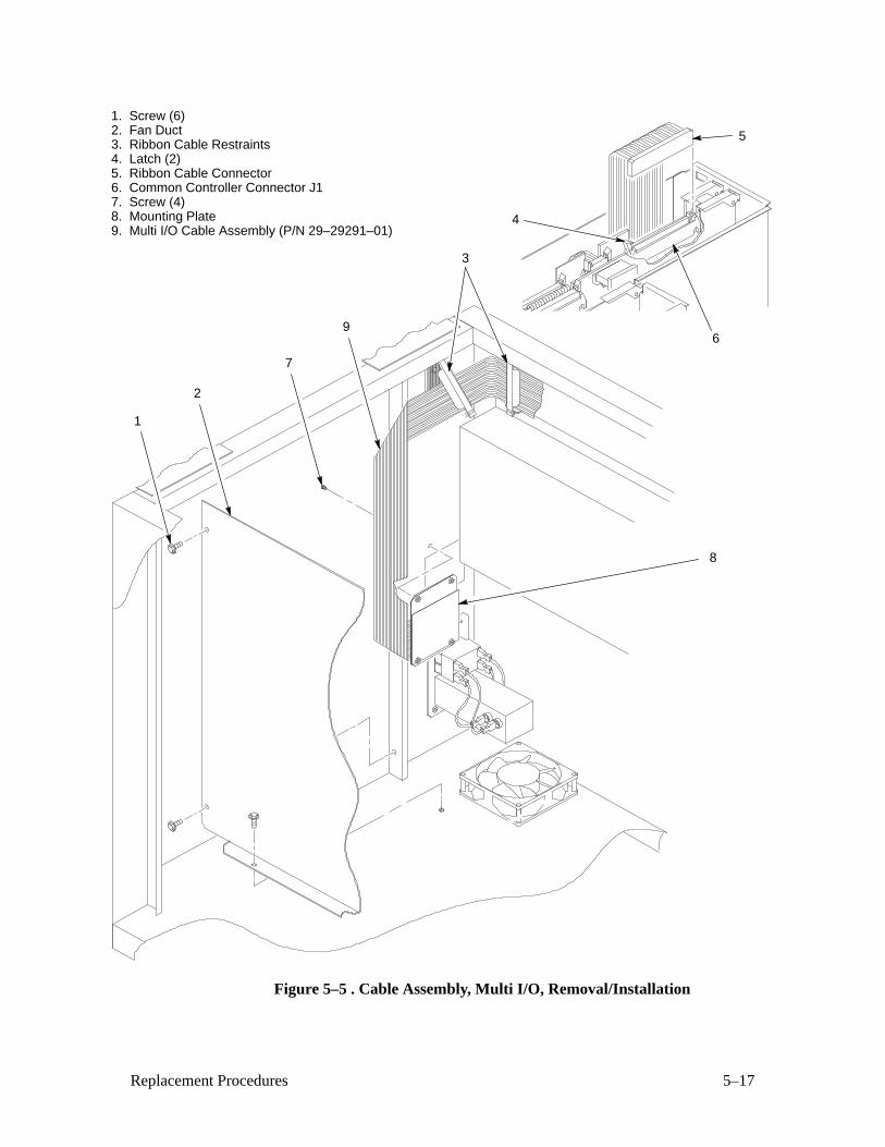
5–17Replacement Procedures
1. Screw (6)2. Fan Duct3. Ribbon Cable Restraints4. Latch (2)5. Ribbon Cable Connector6. Common Controller Connector J17. Screw (4)8. Mounting Plate9. Multi I/O Cable Assembly (P/N 29–29291–01)
1
3
2
5
4
6
7
8
9
Figure 5–5 . Cable Assembly, Multi I/O, Removal/Installation
5–18 Replacement Procedures
Circuit Breaker (Figure 5–6 )
Removal
1. Prepare the printer for maintenance (page 5–3).
2. Open the rear cabinet door.
3. Remove six screws (1) and move the fan duct (2) aside.
4. Tag and disconnect the four circuit breaker electrical leads (3).
5. Press in on the spring clips (4) and push the circuit breaker (5) out of the
mounting plate (6).
Installation
1. Press the circuit breaker (5) into the mounting plate (6) until the spring
clips (4) snap into place.
CAUTION
Make sure the four leads are connected as shown in Figure 5–6 .
2. Connect the four circuit breaker electrical leads (3) as shown in
Figure 5–6 .
3. Move the fan duct (2) back into position and install the six screws (1).
4. Return the printer to normal operation (page 5–80).
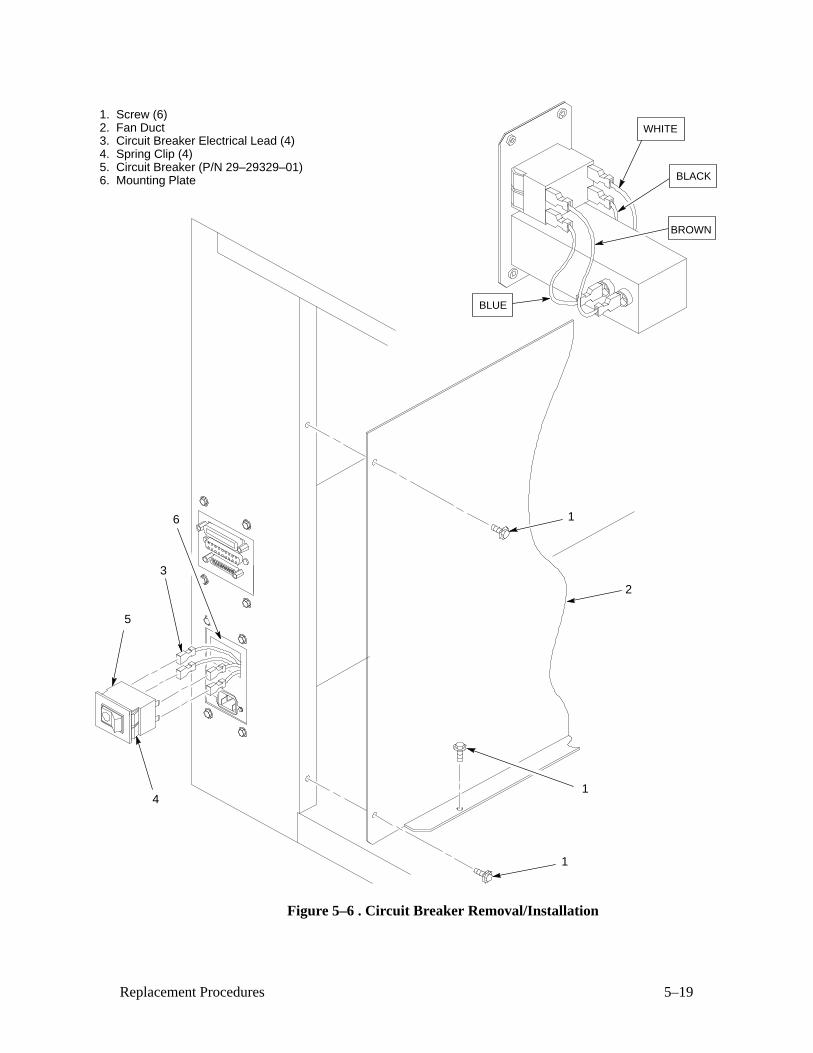
5–19Replacement Procedures
1. Screw (6)2. Fan Duct3. Circuit Breaker Electrical Lead (4)4. Spring Clip (4)5. Circuit Breaker (P/N 29–29329–01)6. Mounting Plate
WHITE
BLACK
BROWN
BLUE
6
3
4
5
2
1
1
1
Figure 5–6 . Circuit Breaker Removal/Installation
5–20 Replacement Procedures
Control Panel Assembly (Figure 5–7 )
Removal
1. Prepare the printer for maintenance (page 5–3).
2. Open the printer cover.
3. Remove the paper guide assembly (page 5–42).
4. Open the connector latches and disconnect the control panel ribbon
connector P1 (1) from connector J3 on the common controller PCBA
(2).
5. Remove the control panel ribbon cable from the wire saddles (3) on the
mechanism base pan.
6. Remove four screws (4) and washers (5).
7. Remove the control panel assembly (6) from the control panel bracket
(7).
Installation
IMPORTANT
You must install two ferrite cores on the control panel cable assembly.Refer to Appendix F.
1. Feed ribbon connector (1) and the ribbon cable through the control
panel bracket (7) and position the control panel assembly (6) on the
bracket.
2. Install but do not tighten four washers (5) and screws (4).
3. Lower the printer cover and center the control panel assembly (6) in the
cutout of the printer cover.
4. Open the printer cover and tighten the four screws (4).
5. Route the control panel ribbon cable along the right side of the printer.
Feed the ribbon cable and ribbon connector (1) through the slot in the
card cage below the card cage fan.
6. Connect the control panel ribbon connector P1 (1) to connector J3 on
the common controller PCBA (2) and close the connector latches.
7. Insert the control panel ribbon cable into the wire saddles (3) on the
mechanism base pan.
8. Install the paper guide assembly (page 5–42).
9. Return the printer to normal operation (page 5–80).
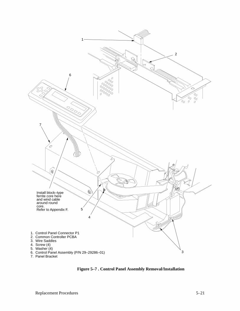
5–21Replacement Procedures
1. Control Panel Connector P1 2. Common Controller PCBA3. Wire Saddles4. Screw (4)5. Washer (4)6. Control Panel Assembly (P/N 29–29286–01)7. Panel Bracket
4
5
6
7
3
Install block–typeferrite core here
Refer to Appendix F.
and wind cablearound roundcore.
1
2
Figure 5–7 . Control Panel Assembly Removal/Installation

5–22 Replacement Procedures
Cover Assembly, Hammer Bank (Figure 5–8 )
Removal
1. Prepare the printer for maintenance (page 5–3).
2. Remove the shuttle frame assembly (page 5–66).
3. Rotate hammer bank cover assembly (1) away from hammer bank (2).
4. Remove hammer bank cover assembly (1) from alignment pins (3).
Installation
CAUTION
The hammer bank contains a strong magnet. To prevent damage to thehammer tips, do not let the hammer bank cover assembly snap intoplace as the hammer bank magnet attracts it. Any impact of the coveragainst the hammer bank can break hammer tips.
1. With the thick plate facing the hammer bank (2), engage the hammer
bank cover assembly (1) on the alignment pins (3).
2. Rotate the hammer bank cover assembly (1) until it lies flush on the
hammer bank (2). Check that the hammer bank cover assembly is
properly positioned over the alignment pins (3) and hammer tips.
3. Install the shuttle frame assembly (page 5–66).
4. Return the printer to normal operation (page 5–80).
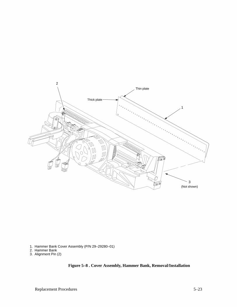
5–23Replacement Procedures
1. Hammer Bank Cover Assembly (P/N 29–29280–01)2. Hammer Bank3. Alignment Pin (2)
1
2
3(Not shown)
Thin plate
Thick plate
Figure 5–8 . Cover Assembly, Hammer Bank, Removal/Installation
5–24 Replacement Procedures
Cover Assembly, Shuttle (Figure 5–9 )
Removal
1. Prepare the printer for maintenance (page 5–3).
2. Open the printer cover.
3. Loosen the shuttle cover screws (1).
4. Grasping the edges of the shuttle cover assembly (2), tilt up the rear
edge and lift the shuttle cover assembly out of the printer.
Installation
1. Place the shuttle cover assembly (2) in the printer. Tilt the forward edgeof the cover down slightly and work the cover into position.
2. Tighten the shuttle cover screws (1).
3. Return the printer to normal operation (page 5–80).
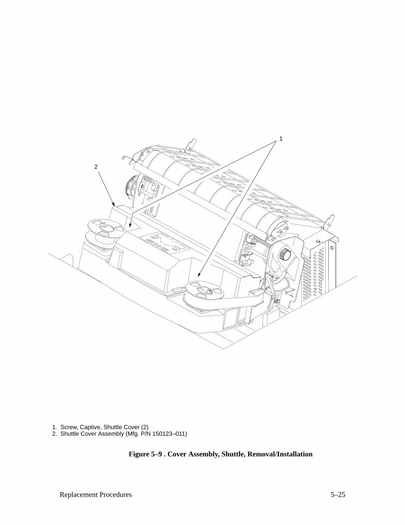
5–25Replacement Procedures
1. Screw, Captive, Shuttle Cover (2)2. Shuttle Cover Assembly (Mfg. P/N 150123–011)
1
2
Figure 5–9 . Cover Assembly, Shuttle, Removal/Installation
5–26 Replacement Procedures
Fan Assembly, Card Cage (Figure 5–10 )
Removal
1. Prepare the printer for maintenance (page 5–3).
2. Open the printer cover.
3. Remove the paper guide assembly (page 5–42).
4. Remove the power supply PCBA (page 5–50).
5. Remove the nut (1) and ground wire (2).
6. Remove four screws (3).
7. Disconnect the fan cable connector (4).
8. Remove the card cage fan assembly (5) and fan guard (6) from the card
cage (7).
Installation
1. Connect the fan cable connector (4).
2. Position the card cage fan assembly (5) and fan guard (6) in the card
cage (7).
3. Install four screws (3).
4. Install the ground wire (2) and nut (1).
5. Install the power supply PCBA (page 5–50).
6. Install the paper guide assembly (page 5–42).
7. Return the printer to normal operation (page 5–80).
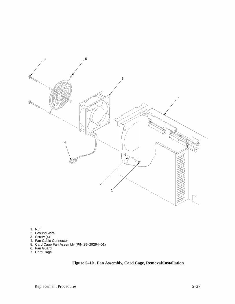
5–27Replacement Procedures
1. Nut2. Ground Wire3. Screw (4)4. Fan Cable Connector5. Card Cage Fan Assembly (P/N 29–29294–01)6. Fan Guard7. Card Cage
3
4
5
6
7
2
1
Figure 5–10 . Fan Assembly, Card Cage, Removal/Installation
5–28 Replacement Procedures
Fan Assembly, Cabinet Exhaust (Figure 5–11 )
Removal
1. Prepare the printer for maintenance (page 5–3).
2. Open the floor cabinet rear door.
3. Remove six screws (1) and move the fan duct (2) aside.
4. Remove four screws (3) securing the cabinet exhaust fan assembly (4).
5. Disconnect the fan cable connector (5).
6. Remove the cabinet exhaust fan assembly (4) and fan guard (6).
Installation
1. Connect the fan cable connector (5).
2. Position the cabinet exhaust fan assembly (4) and fan guard (6) on the
cabinet floor.
3. Install six screws (3) securing the cabinet exhaust fan assembly (4).
4. Move the fan duct (2) back into position and install the four screws (1).
5. Return the printer to normal operation (page 5–80).
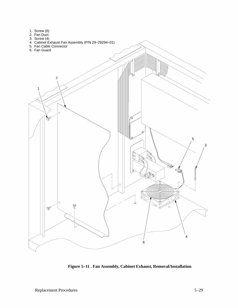
5–29Replacement Procedures
1. Screw (6)2. Fan Duct3. Screw (4)4. Cabinet Exhaust Fan Assembly (P/N 29–29294–01)5. Fan Cable Connector6. Fan Guard
3
1
2
6
5
4
Figure 5–11 . Fan Assembly, Cabinet Exhaust, Removal/Installation
5–30 Replacement Procedures
Fan Assembly, Hammer Bank (Figure 5–12 )
Removal
1. Prepare the printer for maintenance (page 5–3).
2. Remove the shuttle cover assembly (page 5–24).
3. Remove three screws (1).
4. Reach under the base casting (2) and disconnect the hammer bank fan
cable connector (3).
NOTE: The hammer bank fan assembly is removed by angling it up and out
from beneath the shuttle motor.
5. Remove the hammer bank fan assembly (4) from the base casting (2).
Installation
NOTE: The hammer bank fan assembly is installed by angling it down and
under the shuttle motor.
1. Feed the hammer bank fan cable connector (3) through the slot in the
fan well of the base casting (2).
2. Open the floor cabinet front door.
3. Reaching up under the base casting (2) from inside the cabinet, route the
fan cable to right and angle the hammer bank fan assembly (4) down
into the fan well.
4. Connect the hammer bank fan cable connector (5).
5. Close the floor cabinet front door.
6. Install three screws (1).
7. Install the shuttle cover assembly (page 5–24).
8. Return the printer to normal operation (page 5–80).
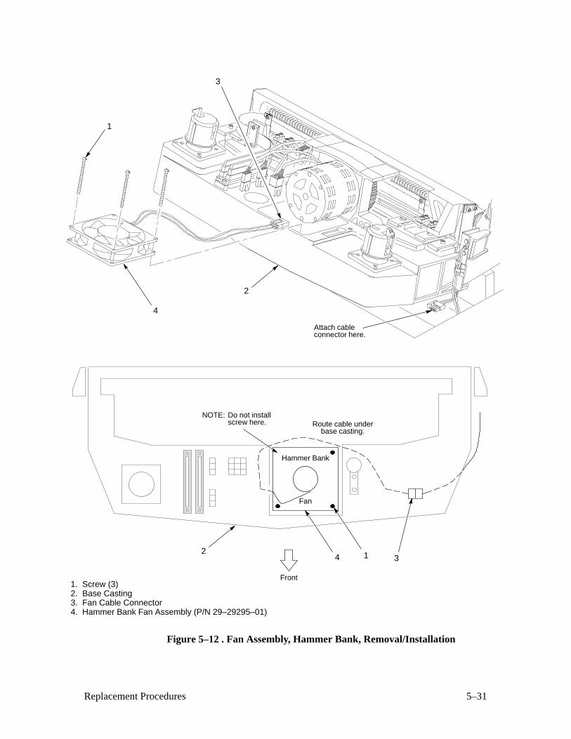
5–31Replacement Procedures
1. Screw (3)2. Base Casting3. Fan Cable Connector4. Hammer Bank Fan Assembly (P/N 29–29295–01)
Front
Hammer Bank
Fan
3
Route cable underbase casting.
24 1
NOTE: Do not installscrew here.
1
4
3
2
Attach cableconnector here.
Figure 5–12 . Fan Assembly, Hammer Bank, Removal/Installation
5–32 Replacement Procedures
Hammer Spring Assembly (Figure 5–13 )
Removal
1. Prepare the printer for maintenance (page 5–3).
2. Remove the shuttle frame assembly (page 5–66).
3. Remove the hammer bank cover assembly (page 5–22).
4. Remove three 5/64 inch socket head screws from the old hammer fret.
5. Using the pointed end of the nylon stick supplied in the hammer spring
replacement kit, carefully pry the old hammer fret off its mounting pins
as shown in Figure 5–13 .
6. Discard the old hammer fret and mounting screws.
Installation
IMPORTANT
FRET ONE is on the RIGHT END of the hammer bank as you face thehammer springs. FRET SEVEN is the LEFT END of the hammer bank.If you accidently bend the wrong hammer, DO NOT attempt to rebendthe hammer and do not install that fret.
1. If you are replacing one of the inner frets, go to step 2.
If you are replacing fret seven, bend the left–most hammer spring as
shown in Figure 5–13 before removing it from the box. If you are
replacing fret one, bend the right–most hammer spring as shown inFigure 5–13 before removing it from the box. Go to step 2.
2. Remove the new fret and mounting screws from the box.
3. Install the new fret on the hammer bank mounting pins and press it into
position with the flat end of the nylon stick supplied in the hammer
spring replacement kit.
4. Install the screws from the replacement kit in the order shown in
Figure 5–13 . Torque each screw to 8 in–lbs.
5. Install the hammer bank cover assembly (page 5–22).
6. Install the shuttle frame assembly (page 5–66).
7. Return the printer to normal operation (page 5–80).
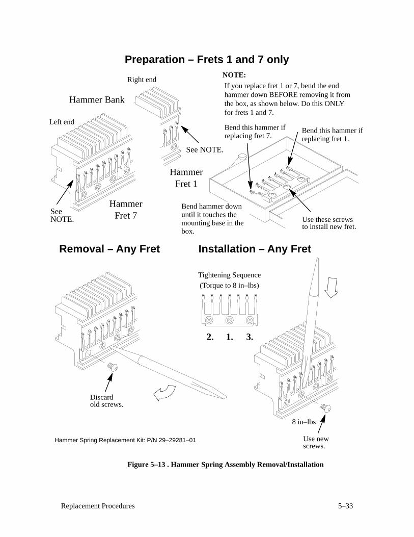
5–33Replacement Procedures
Hammer Spring Replacement Kit: P/N 29–29281–01
HammerFret 1
HammerFret 7
Hammer Bank
See
See NOTE.
Preparation – Frets 1 and 7 only
NOTE.
Bend this hammer ifreplacing fret 7.
NOTE:
If you replace fret 1 or 7, bend the endhammer down BEFORE removing it fromthe box, as shown below. Do this ONLYfor frets 1 and 7.
Bend this hammer ifreplacing fret 1.
Use these screwsto install new fret.
Removal – Any Fret
Discardold screws.
Installation – Any Fret
1.2. 3.
8 in–lbs
Tightening Sequence
(Torque to 8 in–lbs)
Use newscrews.
Bend hammer downuntil it touches themounting base in thebox.
Left end
Right end
Figure 5–13 . Hammer Spring Assembly Removal/Installation
5–34 Replacement Procedures
Magnetic Pick–up (MPU) Assembly (Figure 5–14 )
Removal
1. Prepare the printer for maintenance (page 5–3).
2. Remove the shuttle cover (page 5–24).
3. Disconnect the magnetic pick–up (MPU) cable connector (1).
4. Loosen the MPU clamp screw (2).
5. Remove the MPU assembly (3) by unscrewing it from the MPU bracket
(4).
Installation
1. Install the MPU assembly (3) by screwing it into the MPU bracket (4).
2. Using a feeler gauge, adjust the gap between the MPU assembly (3) and
the flywheel (5) to 0.010 ± .001 inch. Torque the MPU clamp screw (2)
to 19 ± 1 inch–pounds.
3. Check the gap between the MPU assembly (3) and the flywheel (5) with
a feeler gauge:
c. If the gap is 0.010 ± .001 inch, go to step 4.
d. If the gap is not 0.010 ± 0.001 inch, loosen the MPU clamp
screw (2) and go back to step 2.
4. Connect the magnetic pick–up (MPU) cable connector (1).
5. Install the shuttle cover (page 5–24).
6. Return the printer to normal operation (page 5–80).
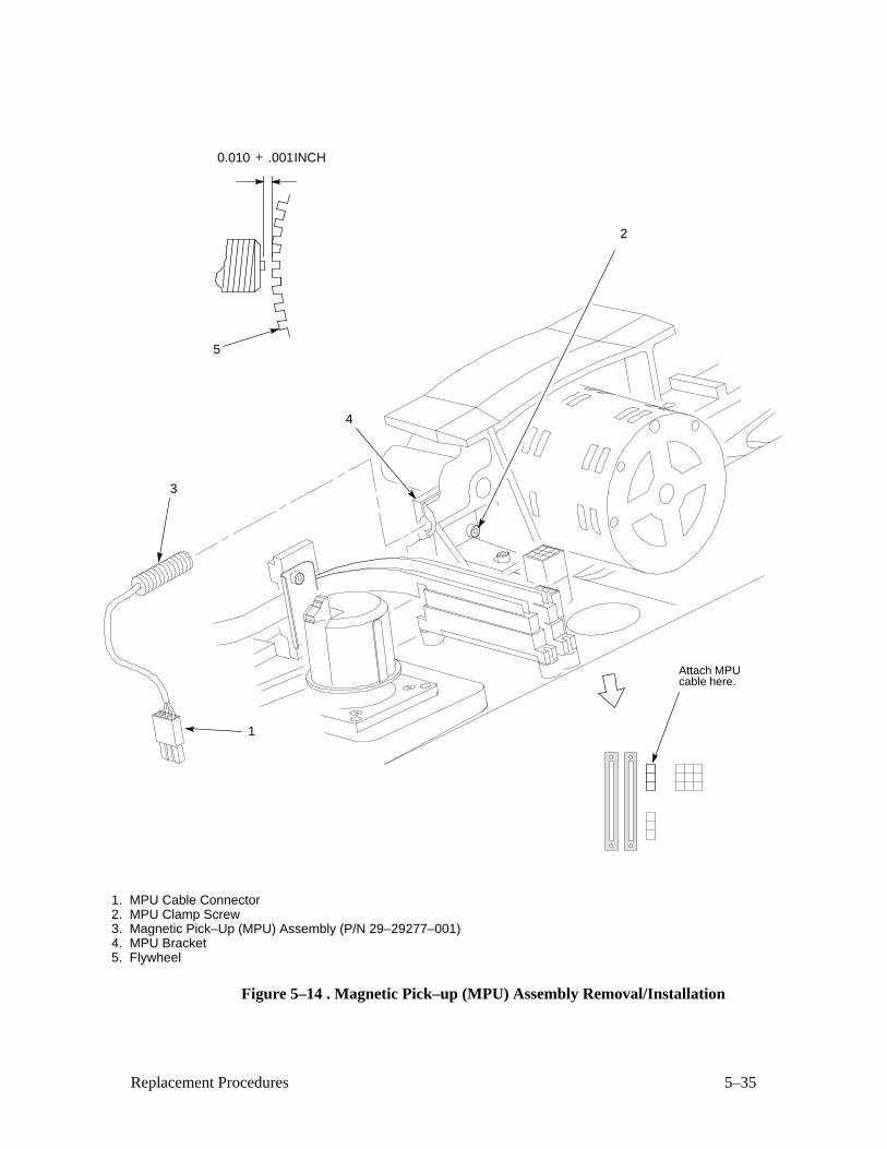
5–35Replacement Procedures
1. MPU Cable Connector2. MPU Clamp Screw3. Magnetic Pick–Up (MPU) Assembly (P/N 29–29277–001)4. MPU Bracket5. Flywheel
0.010 + .001INCH
1
2
3
4
5
Attach MPUcable here.
Figure 5–14 . Magnetic Pick–up (MPU) Assembly Removal/Installation
5–36 Replacement Procedures
Motor Assembly, Ribbon Drive (Figure 5–15 )
Removal
NOTE: The procedure below is the same for the left and right ribbon drivemotor assemblies.
1. Prepare the printer for maintenance (page 5–3).
2. Remove the ribbon.
3. Remove the ribbon hub (page 5–58).
4. Remove two screws (1) and washers (2).
5. Lift the ribbon drive motor (3) and its cable from base casting (4).
6. Disconnect the ribbon motor cable connector (5).
7. Loosen the set screw (6) and remove the collar (7) and shaft extension
(8).
Installation
IMPORTANT
You must install a ferrite core on the ribbon motor cable assembly. Referto Appendix F.
NOTE: The procedure below is the same for the left and right ribbon drive
motor assemblies.
1. Install the shaft extension (8) and collar (7), and tighten the set screw
(6).
2. Connect the ribbon motor cable connector (5) and position the ribbon
drive motor (3) in the base casting (4).
3. Install screws (1) and washers (2) to secure the upper right and lower
left corners of the ribbon drive motor assembly (3).
4. Install the ribbon hub (page 5–58).
5. Return the printer to normal operation (page 5–80).
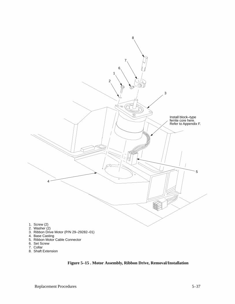
5–37Replacement Procedures
1. Screw (2)2. Washer (2)3. Ribbon Drive Motor (P/N 29–29282–01)4. Base Casting5. Ribbon Motor Cable Connector6. Set Screw7. Collar8. Shaft Extension
3
2
5
4
1
6
7
8
Install block–typeferrite core here.Refer to Appendix F.
Figure 5–15 . Motor Assembly, Ribbon Drive, Removal/Installation
5–38 Replacement Procedures
Motor Assembly, Paper Feed (Figure 5–16 )
Removal
1. Prepare the printer for maintenance (page 5–3).
2. Open the printer cover.
3. Remove the platen open belt cover (1) by squeezing the top and bottom
to release the plastic tabs from the slots in the side plate.
4. Loosen the set screw (2) and remove the paper feed motor pulley (3),
collar (4), and paper feed timing belt (5).
5. Disconnect the paper feed motor electrical connector (6).
6. Remove the motor mount bolts (7) and nuts (8).
7. Remove the paper feed motor assembly (9).
Installation
1. Position the paper feed motor assembly (9) on the right side plate and
install the motor mount bolts (7) and nuts (8) finger tight.
2. Connect the paper feed motor electrical connector (6).
3. Install the paper feed motor pulley (3), collar (4), and timing belt (5).
4. Align the paper feed motor pulley (3) with the splined shaft pulley (10).
5. Hold the collar (4) snug against the motor pulley (3) and tighten the set
screw (2).
6. Using a force gauge, apply 12 pounds of tension to the paper feed motor
assembly (12).
7. Reduce tension to 9 pounds and torque the motor mount bolts (7) to
18 ± 1 inch–pounds.
8. Snap the platen open belt cover (1) into the slots in the side plate.
9. Return the printer to normal operation (page 5–80).
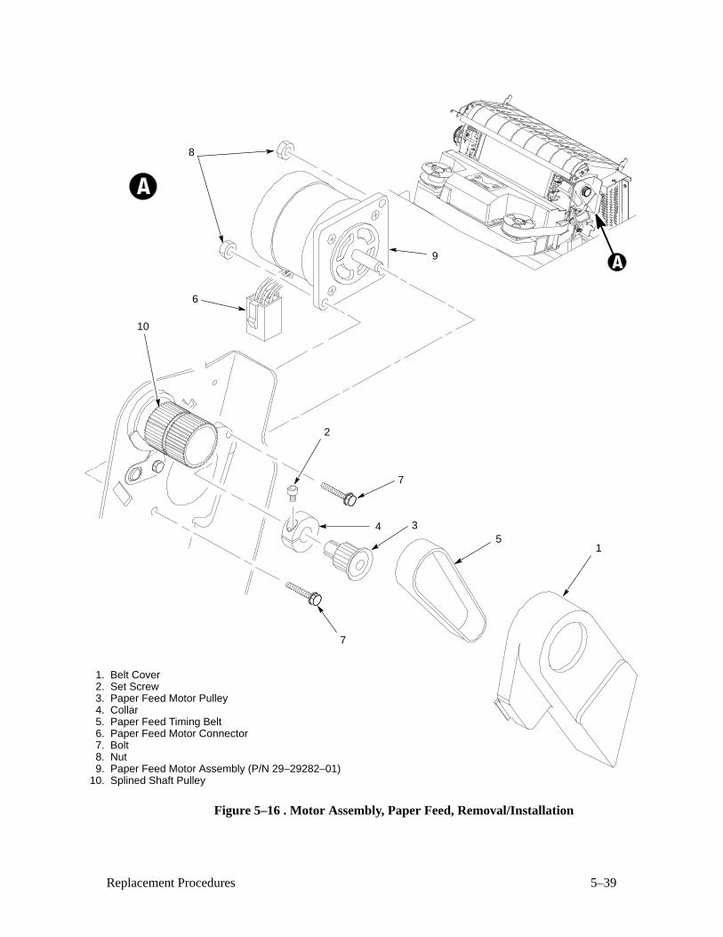
5–39Replacement Procedures
1. Belt Cover2. Set Screw3. Paper Feed Motor Pulley4. Collar5. Paper Feed Timing Belt6. Paper Feed Motor Connector7. Bolt8. Nut9. Paper Feed Motor Assembly (P/N 29–29282–01)
10. Splined Shaft Pulley
1
2
34
7
7
10
9
6
8
5
Figure 5–16 . Motor Assembly, Paper Feed, Removal/Installation
5–40 Replacement Procedures
Motor Assembly, Platen Open (Figure 5–17 )
Removal
1. Prepare the printer for maintenance (page 5–3).
2. Remove the card cage fan assembly (page 5–26).
3. Remove the platen open belt cover (1) by squeezing the top and bottom
to release the plastic tabs from the slots in the side plate.
4. Loosen the motor mount screws (2).
5. Remove the platen open belt (3).
6. Loosen the collar set screw (4) and remove the motor pulley (5).
7. Disconnect the platen motor cable connector (6).
8. Remove the motor mount screws (2) and nut ring (7).
9. Remove the platen open motor assembly (8).
Installation
1. Position the platen open motor assembly (8) and nut ring (7) and install
the motor mount screws (2).
2. Install the motor pulley (5), align it with the platen pulley (9), and
tighten the collar set screw (4).
3. Connect the platen motor cable connector (6).
4. Install the platen open belt (3).
5. Close the forms thickness lever all the way.
6. Make sure the collar of the platen pulley (9) clears the left ribbon guide
with the platen fully closed.
a. If not, rotate the platen pulley (9) until the collar clears the left
ribbon guide and tighten the platen pulley set screw (10). Go to
step 7.
b. If the collar clears the ribbon guide with the forms thickness
lever closed, go to step 7.
7. Using a force gauge, apply 10 pounds of tension to the platen open
motor assembly (8), reduce tension to 5 pounds and torque the motor
mount screws (2) to 11 ± 1 inch–pounds.
8. Snap the platen open belt cover (1) into the slots in the side plate.
9. Install the card cage fan assembly (page 5–26).
10. Return the printer to normal operation (page 5–80).
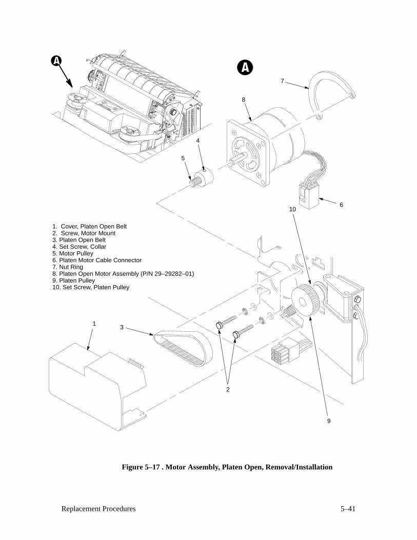
5–41Replacement Procedures
1. Cover, Platen Open Belt2. Screw, Motor Mount3. Platen Open Belt4. Set Screw, Collar5. Motor Pulley6. Platen Motor Cable Connector7. Nut Ring8. Platen Open Motor Assembly (P/N 29–29282–01)9. Platen Pulley10. Set Screw, Platen Pulley
13
4
8
6
5
9
10
2
7
Figure 5–17 . Motor Assembly, Platen Open, Removal/Installation
5–42 Replacement Procedures
Paper Guide Assembly (Figure 5–18 )
Removal
1. Prepare the printer for maintenance (page 5–3).
2. Open the printer cover.
3. Loosen—do not remove—the hold–down screw (1).
4. Slide the paper guide assembly (2) to the left and lift it off the card cage
(3).
Installation
1. Position the paper guide assembly (2) offset slightly to the left on thecard cage (3).
2. Slide the paper guide assembly (2) to the right and engage the tabs on
the underside of the paper guide assembly with the left edge of the card
cage.
3. Slide the paper guide assembly (2) to the right as far as it will go.
4. Tighten the hold–down screw (1).
5. Return the printer to normal operation (page 5–80).
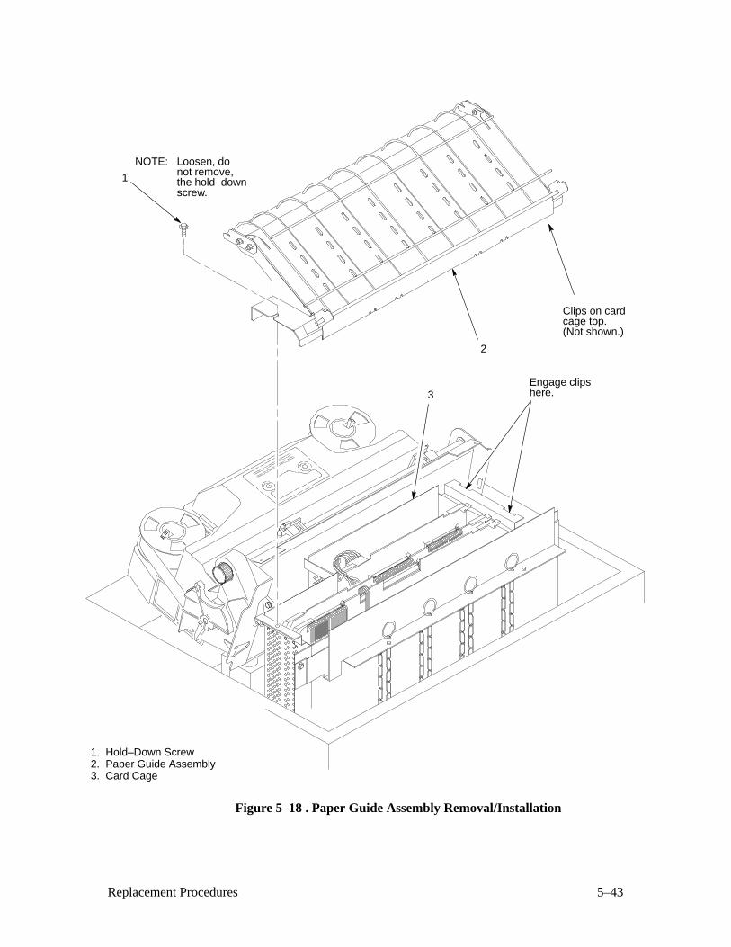
5–43Replacement Procedures
1. Hold–Down Screw2. Paper Guide Assembly3. Card Cage
1
2
NOTE: Loosen, donot remove,the hold–downscrew.
3
Clips on cardcage top.(Not shown.)
Engage clipshere.
Figure 5–18 . Paper Guide Assembly Removal/Installation
5–44 Replacement Procedures
Paper Ironer (Figure 5–19 )
Removal
1. Remove the shuttle frame assembly (page 5–66).
2. Move the forms thickness lever (1) to the open position.
WARNING
Over time, the upper edge of the paper ironer can become sharp. Toavoid cutting yourself, grasp the paper ironer on the sides.
3. Push back at the ends of the paper ironer (2) to disengage the tabs, then
lift it up and out.
Installation
WARNING
Over time, the upper edge of the paper ironer can become sharp. Toavoid cutting yourself, grasp the paper ironer on the sides.
1. Position the paper ironer (2) so that the lip on the upper edge faces the
front of the printer.
2. Push the paper ironer (2) down into the slots until the tabs engage.
3. Install the shuttle frame assembly (page 5–66).
4. Return the printer to normal operation (page 5–80).
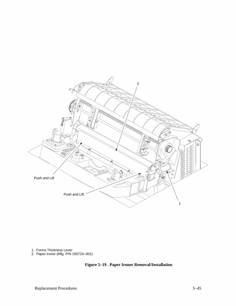
5–45Replacement Procedures
1. Forms Thickness Lever2. Paper Ironer (Mfg. P/N 150724–001)
2
Push and Lift
Push and Lift
1
Figure 5–19 . Paper Ironer Removal/Installation
5–46 Replacement Procedures
PCBA, Common Controller (Figure 5–20 )
CAUTION
To prevent electrostatic damage to electronic components, wear aproperly grounded static wrist strap when handling PCBAs.
Removal
1. Prepare the printer for maintenance (page 5–3).
2. Open the printer cover.
3. Remove the paper guide assembly (page 5–42).
4. Open the connector latches and disconnect the multi I/O ribbon cable (1)from connector J1 (2).
5. Open the connector latches and disconnect the CCB/Mech. Driver cable
connector (3) from connector J2 (4).
6. Open the connector latches and disconnect the control panel ribbon
cable (5) from connector J3 (6).
7. Lift the ejection levers (7).
8. Grasp the common controller PCBA (8) by the ejection levers and pull it
up and out of the card cage (9).
9. Remove the program PROMs, font PROMs, memory paging PROM
(page 5–52), and host terminating resistors (page 5–56).
Installation
1. Install the program PROMs, font PROMs, memory paging PROM (page
5–52), and host terminating resistors (page 5–56) onto the replacement
PCBA.
2. Slide the common controller PCBA (8) down into the card cage (9).
Engage the card edge connectors in the connector at the bottom of the
card cage (9).
3. Lower the ejection levers (7) to the closed position.
4. Connect the control panel ribbon cable (5) to connector J3 (6).
5. Connect the CCB/Mech. Driver cable connector (3) to connector J2 (4).
6. Connect the multi I/O ribbon cable (1) to connector J1 (2).
7. Install the paper guide assembly (page 5–42).
8. If PROMs were replaced, adjust the hammer phasing (page 4–4).
9. Return the printer to normal operation (page 5–80).
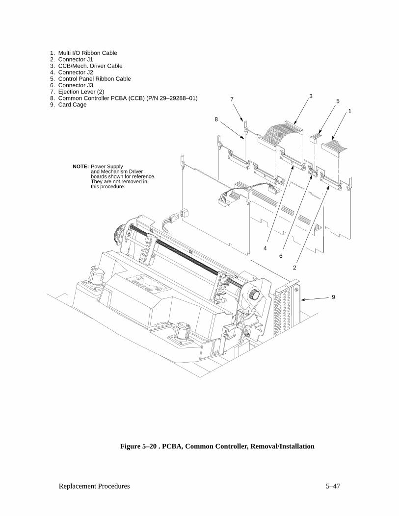
5–47Replacement Procedures
1. Multi I/O Ribbon Cable2. Connector J13. CCB/Mech. Driver Cable4. Connector J25. Control Panel Ribbon Cable6. Connector J37. Ejection Lever (2)8. Common Controller PCBA (CCB) (P/N 29–29288–01)9. Card Cage
Power Supplyand Mechanism Driverboards shown for reference.They are not removed inthis procedure.
NOTE:
1
357
8
9
2
46
Figure 5–20 . PCBA, Common Controller, Removal/Installation
5–48 Replacement Procedures
PCBA, Mechanism Driver (Figure 5–21 )
CAUTION
To prevent electrostatic damage to electronic components, wear aproperly grounded static wrist strap when handling PCBAs.
Do not flex the board or grasp components on the PCBA duringremoval/installation. Damage to components may result. Handle theboard carefully by the ejections levers, sides, or the heat sink.
Removal
1. Prepare the printer for maintenance (page 5–3).
2. Open the printer cover.
3. Remove the paper guide assembly (page 5–42).
4. Open the connector latches and disconnect the CCB/Mech. Driver
ribbon cable (1) from connector J6 (2).
5. Disconnect the power supply cable (3) from connector J7 (4).
6. Lift the ejection levers (5).
7. Grasp the mechanism driver PCBA (6) by the ejection levers and pull it
up and out of the card cage (7).
Installation
1. Slide the mechanism driver PCBA (6) down into the card cage (7).
Engage the card edge connectors in the connectors at the bottom of thecard cage.
2. Lower the ejection levers (5) to the closed position.
3. Connect the power supply cable (3) to connector J7 (4).
4. Connect the CCB/Mech. Driver ribbon cable (1) to connector J6 (2) and
close the connector latches.
5. Install the paper guide assembly (page 5–42).
6. Return the printer to normal operation (page 5–80).
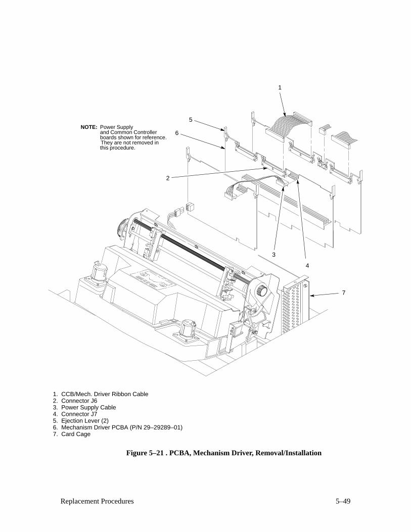
5–49Replacement Procedures
1. CCB/Mech. Driver Ribbon Cable2. Connector J63. Power Supply Cable4. Connector J75. Ejection Lever (2)6. Mechanism Driver PCBA (P/N 29–29289–01)7. Card Cage
Power Supplyand Common Controllerboards shown for reference.They are not removed inthis procedure.
NOTE:
4
2
3
7
5
6
1
Figure 5–21 . PCBA, Mechanism Driver, Removal/Installation
5–50 Replacement Procedures
PCBA, Power Supply (Figure 5–22 )
WARNING
To prevent injury from electric shock, wait at least one minute aftershutting off power before removing the power supply PCBA. Do nottouch components or flex the board during removal/installation. Handlethe board by the ejections levers and the sides. Wear a properlygrounded static wrist strap when handling the power supply PCBA.
Removal
1. Prepare the printer for maintenance (page 5–3).
2. Open the printer cover.
3. Remove the paper guide assembly (page 5–42).
4. Disconnect the mechanism driver power supply cable (1) from
connector J102 (2).
5. Lift the ejection levers (3).
6. Grasp the power supply PCBA (4) by the ejection levers and pull it up
about four inches.
7. Disconnect the circuit breaker cable (5) from connector J1 (6).
8. Remove the power supply PCBA (4) from the card cage (7).
Installation
1. Slide the power supply PCBA (4) into the card cage (7) about two
inches.
2. Connect the circuit breaker cable (5) to connector J1 (6).
3. Slide the power supply PCBA (4) into the card cage (7), engaging the
ejection levers (3) under the lip of the card cage (7).
4. Slowly lower the ejection levers (3) to the closed position.
5. Connect the mechanism driver power supply cable (1) to connector J102
(2).
6. Install the paper guide assembly (page 5–42).
7. Return the printer to normal operation (page 5–80).
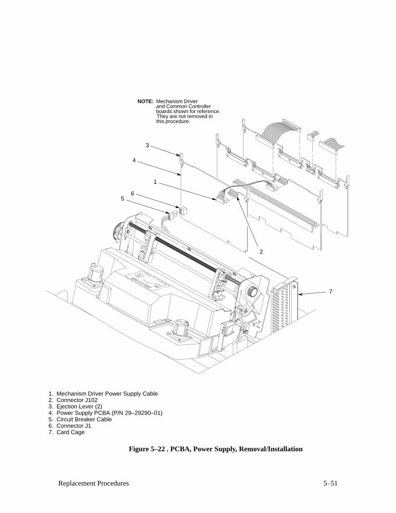
5–51Replacement Procedures
1. Mechanism Driver Power Supply Cable2. Connector J1023. Ejection Lever (2)4. Power Supply PCBA (P/N 29–29290–01)5. Circuit Breaker Cable6. Connector J17. Card Cage
Mechanism Driverand Common Controllerboards shown for reference.They are not removed inthis procedure.
NOTE:
2
7
3
4
1
65
Figure 5–22 . PCBA, Power Supply, Removal/Installation
5–52 Replacement Procedures
PROMs, Chips, and ICs on the CCB (Figure 5–23 )
Removal
1. Prepare the printer for maintenance (page 5–3).
2. Remove the common controller PCBA (page 5–46).
CAUTION
To prevent electrostatic damage to electronic components, wear aproperly grounded static wrist strap when handling PCBAs andcomponents.
3. Using a chip puller, remove the defective chip(s). Locations are shown
in Figure 5–23 .
Installation
CAUTION
To prevent electrostatic damage to electronic components, wear aproperly grounded static wrist strap when handling PCBAs andcomponents.
1. Using a chip installation tool, install chip(s). Locations are shown in
Figure 5–23 .
2. Install the common controller PCBA (page 5–46).
3. If you changed DPU or font PROMs, adjust hammer phasing (page
4–4).
4. Return the printer to normal operation (page 5–80).
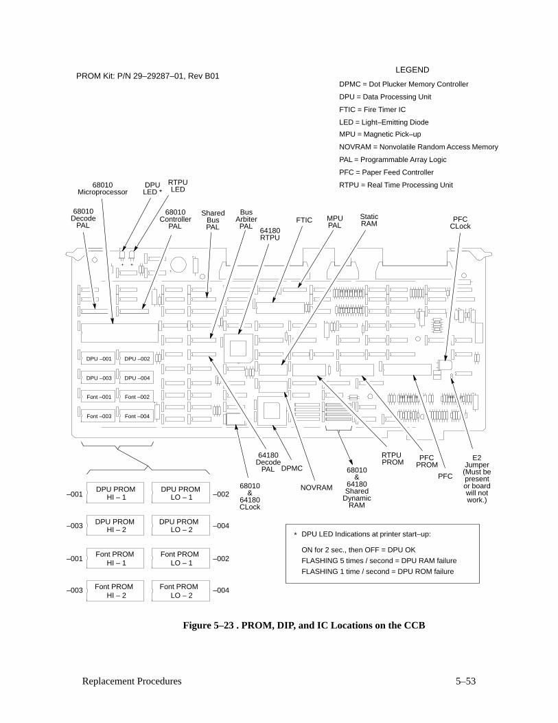
5–53Replacement Procedures
68010Microprocessor
DPU –001 DPU –002
DPU –003 DPU –004
Font –001
Font –003
Font –002
Font –004
68010Controller
PAL
68010Decode
PAL
SharedBusPAL
BusArbiterPAL
DPMC
FTIC MPUPAL
PFC
PFC
NOVRAM
StaticRAM
PROMPROM
64180RTPU
64180Decode
PAL
HI – 1 LO – 1
HI – 2 LO – 2
HI – 1
HI – 2
LO – 1
LO – 2
DPU PROM DPU PROM
DPU PROM DPU PROM
Font PROM Font PROM
Font PROMFont PROM
DPMC = Dot Plucker Memory Controller
FTIC = Fire Timer IC
NOVRAM = Nonvolatile Random Access Memory
PAL = Programmable Array Logic
PFC = Paper Feed Controller
RTPU = Real Time Processing Unit
LEGEND
DPULED *
DPU LED Indications at printer start–up:*
RTPU
ON for 2 sec., then OFF = DPU OK
FLASHING 5 times / second = DPU RAM failure
FLASHING 1 time / second = DPU ROM failure
DPU = Data Processing Unit
MPU = Magnetic Pick–up
LED = Light–Emitting Diode
RTPULED
–001 –002
–003 –004
–001 –002
–003 –004
68010&
64180CLock
68010&
64180
E2Jumper(Must bepresentor boardwill notwork.)
PFCCLock
SharedDynamic
RAM
PROM Kit: P/N 29–29287–01, Rev B01
Figure 5–23 . PROM, DIP, and IC Locations on the CCB
5–54 Replacement Procedures
PROMs, Chips, and ICs on the Mechanism Driver (Figure 5–24 )
Removal
1. Prepare the printer for maintenance (page 5–3).
2. Remove the mechanism driver PCBA (page 5–48).
CAUTION
To prevent electrostatic damage to electronic components, wear aproperly grounded static wrist strap when handling PCBAs andcomponents.
3. Using a chip puller, remove the defective chip(s). Locations are shown
in Figure 5–24 .
Installation
CAUTION
To prevent electrostatic damage to electronic components, wear aproperly grounded static wrist strap when handling PCBAs andcomponents.
1. Using a chip installation tool, install chip(s). Locations are shown in
Figure 5–24 .
2. Install the mechanism driver PCBA (page 5–48).
3. If you changed DPU or font PROMs, adjust hammer phasing (page
4–4).
4. Return the printer to normal operation (page 5–80).
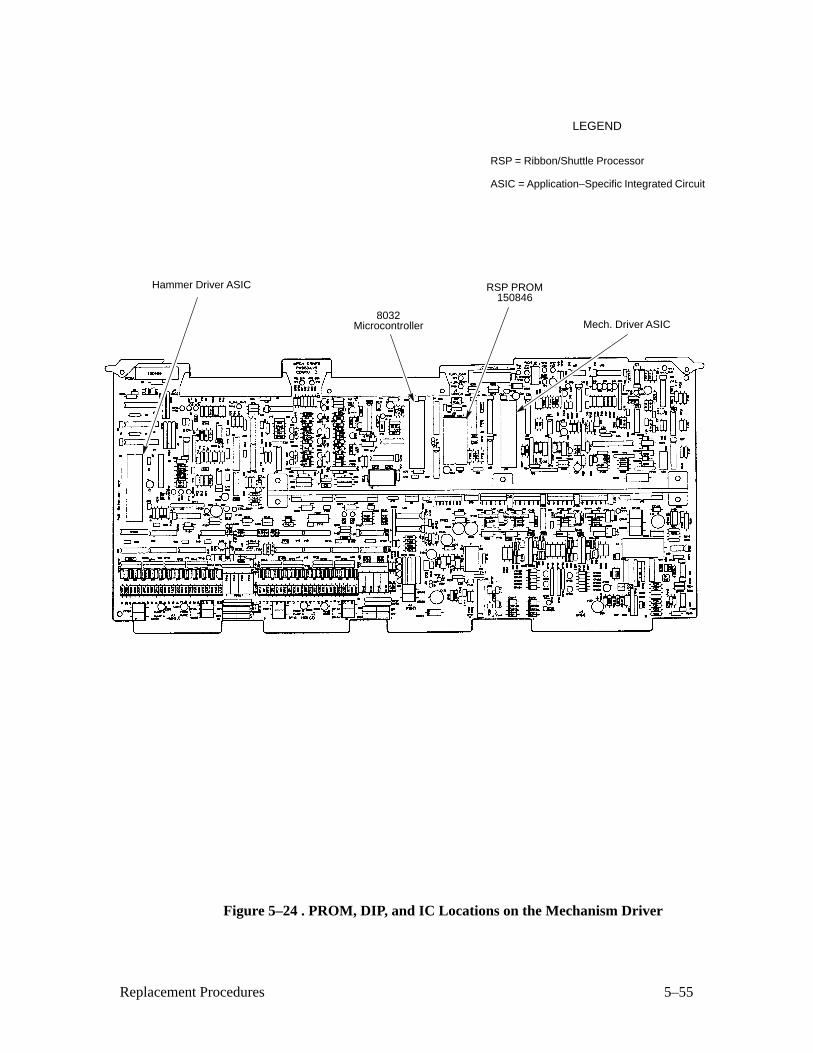
5–55Replacement Procedures
8032Microcontroller
RSP = Ribbon/Shuttle Processor
LEGEND
ASIC = Application–Specific Integrated Circuit
RSP PROM150846
Hammer Driver ASIC
Mech. Driver ASIC
Figure 5–24 . PROM, DIP, and IC Locations on the Mechanism Driver
5–56 Replacement Procedures
Resistors, Terminating (Figure 5–25 )
For parallel interface configurations, the LG06 printer is equipped with 1K
ohm pullup terminating resistors, located at coordinates 12C on the Common
Controller PCBA. The 1K ohm terminating resistors are suitable for most
applications.
If the standard terminating resistor pack is not compatible with the particular
interface driver requirements of the host computer, other values of
pullup/pulldown resistors may be required. Digital provides the 330 ohm
pullup and 220 ohm pulldown alternate terminating resistors. If the 330 ohmpullup resistor is installed, also install the 220 ohm pulldown resistor.
Removal
1. Prepare the printer for maintenance (page 5–3).
2. Remove the Common Controller PCBA (page 5–46).
CAUTION
To prevent electrostatic damage to electronic components, wear aproperly grounded static wrist strap when handling PCBAs andcomponents.
3. Locate the terminating resistor pack (see Figure 5–25 ).
4. Using a chip puller, remove the pack.
Installation
CAUTION
To prevent electrostatic damage to electronic components, wear aproperly grounded static wrist strap when handling PCBAs andcomponents.
1. Using a chip installation tool, install the resistor pack in the correctsocket (see Figure 5–25 ).
2. Install the Common Controller PCBA (page 5–46).
3. Return the printer to normal operation (page 5–80).
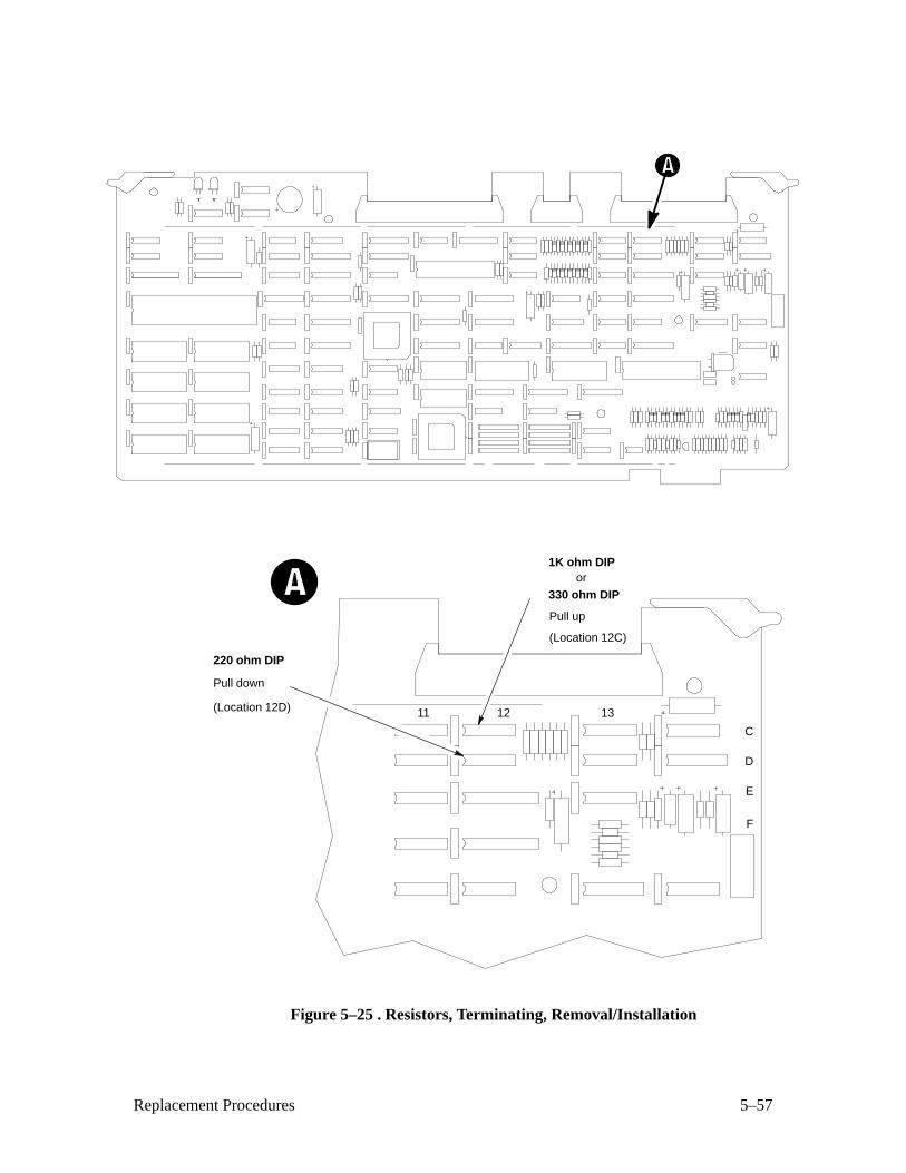
5–57Replacement Procedures
330 ohm DIP
C
D
E
F
12 1311
220 ohm DIP
1K ohm DIPor
(Location 12D)
(Location 12C)
Pull down
Pull up
Figure 5–25 . Resistors, Terminating, Removal/Installation
5–58 Replacement Procedures
Ribbon Hub (Figure 5–26 )
Removal
1. Prepare the printer for maintenance (page 5–3).
2. Remove the printer ribbon.
3. Loosen the screw (1) in the ribbon spool hub (2).
4. Remove the hub (2) from the shaft adapter on the ribbon drive motor
(3).
Installation
1. If the ribbon drive motor has a shaft extension and collar, go to step 2.
If the ribbon drive motor does not have an extension shaft and collar,
begin at step 4.
2. Loosen the collar screw (4).
3. Remove and discard the shaft extension (5) and collar (6).
4. Install the ribbon spool hub (2) over the motor shaft.
5. Tighten the hub screw (1) so that it contacts the flat section of the motor
shaft. Do not overtighten the hub screw.
6. Return the printer to normal operation (page 5–80).
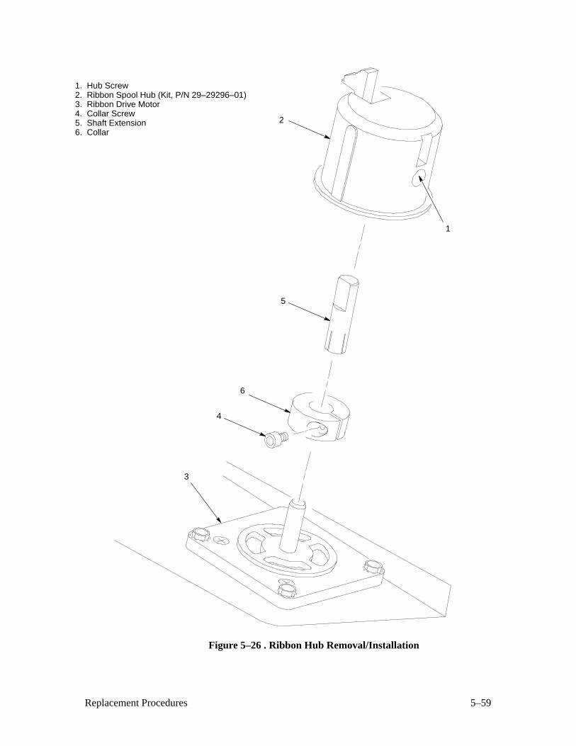
5–59Replacement Procedures
1. Hub Screw 2. Ribbon Spool Hub (Kit, P/N 29–29296–01)3. Ribbon Drive Motor4. Collar Screw5. Shaft Extension6. Collar
5
6
4
2
1
3
Figure 5–26 . Ribbon Hub Removal/Installation
5–60 Replacement Procedures
Ribbon Guide Assembly (L/R) (Figure 5–27 )
Removal
NOTE: Although the right ribbon guide is shown in Figure 5–27 , theremoval procedure is the same for the left ribbon guide.
1. Prepare the printer for maintenance (page 5–3).
2. Open the printer cover.
3. Remove the printer ribbon.
4. Cut the tie–wrap and remove it from the spot tie (1) to free the ribbon
guide cable.
5. Disconnect the ribbon guide connector (2).
6. Remove the two screws (3) and washers (4).
7. Slide the ribbon guide assembly (5) out of the side plate (6).
Installation
NOTE: Although the right ribbon guide is shown in Figure 5–27 , the
installation procedure is the same for the left ribbon guide.
1. Slide the ribbon guide assembly (5) into the side plate (6).
2. Install two screws (3) and washers (4).
3. Connect the ribbon guide connector (2).
4. Tie–wrap the cable to the spot tie (1).
5. Align the ribbon guides (page 4–20).
6. Return the printer to normal operation (page 5–80).
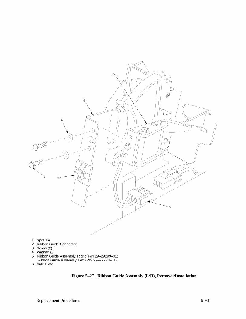
5–61Replacement Procedures
1. Spot Tie2. Ribbon Guide Connector3. Screw (2)4. Washer (2)5. Ribbon Guide Assembly, Right (P/N 29–29299–01)
Ribbon Guide Assembly, Left (P/N 29–29278–01)6. Side Plate
5
6
4
3 1
2
Figure 5–27 . Ribbon Guide Assembly (L/R), Removal/Installation
5–62 Replacement Procedures
Shaft, Splined (Figure 5–28 )
Removal
1. Prepare the printer for maintenance (page 5–3).
2. Open the printer cover.
3. Remove the paper feed timing belt (page 5–4).
4. With grip ring pliers, remove the grip ring (1) from the splined shaft (2).
5. Pull the bearing (3) and spring link (4) with the spring (5) off the splined
shaft (2).
6. Unlock the left and right tractors (6 and 7) and slide them to the center.
7. Remove the screw (8), washer (9), and bearing clamp (10).
8. Grasping the vertical adjustment knob (11), slide the splined shaft (2)
out of the left and right side plates (12 and 13).
Installation
1. Open the doors on the left and right tractors (6 and 7). Position the
tractor belts so the alignment marks are at the top on both tractors.
2. Grasp the vertical adjustment knob (11) and slide the splined shaft (2)through the right side plate (13), tractors (6 and 7), and the left side plate
(12). Make sure the same spline passes the marked groove on each
tractor.
3. Install the bearing clamp (10), washer (9), and screw (8).
4. Apply a thin film of M–3 grease to the bearing (3).
5. Slide the spring link (4) and bearing (3) onto the splined shaft (2).
6. Attach the spring (5) to the left side plate (11) and the spring link (4).
7. Install the grip ring (1) on the splined shaft (2) with 0.010 inches ofclearance between the grip ring and the left side plate (11).
8. Install the paper feed timing belt (page 5–4).
9. Set the paper feed timing belt tension (page 4–6, 5 through 7).
10. Adjust splined shaft skew (page 4–14).
11. Return the printer to normal operation (page 5–80).
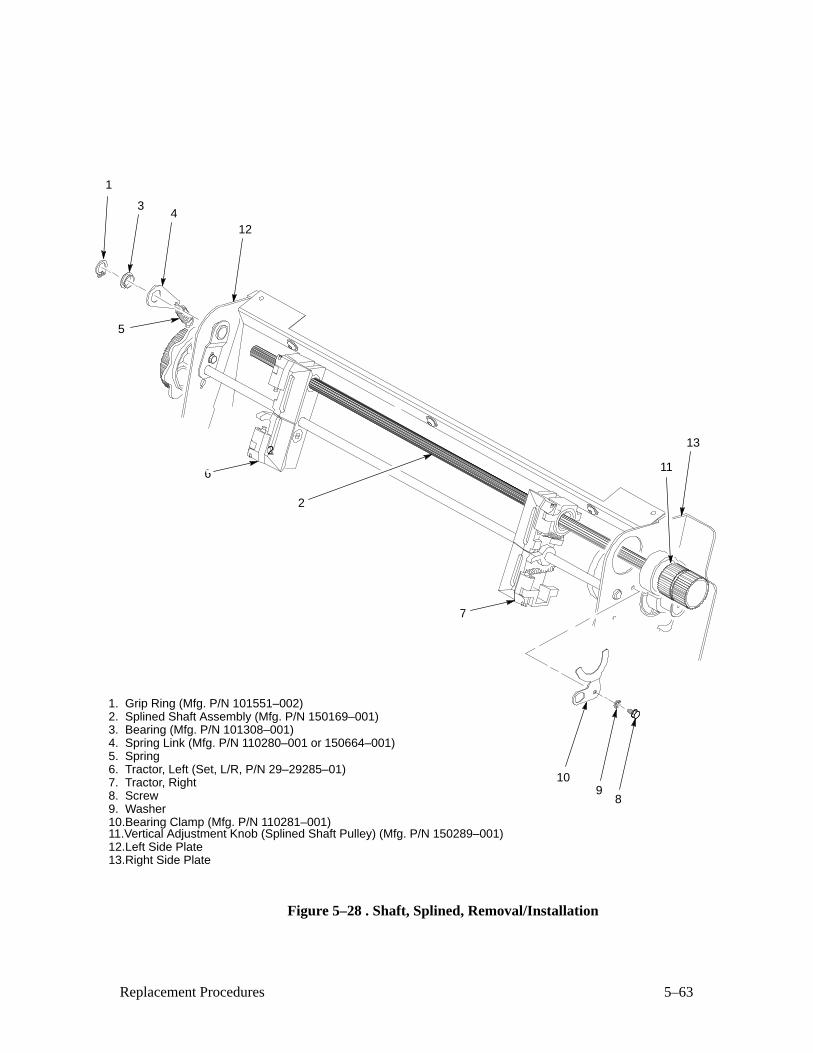
5–63Replacement Procedures
1. Grip Ring (Mfg. P/N 101551–002)2. Splined Shaft Assembly (Mfg. P/N 150169–001)3. Bearing (Mfg. P/N 101308–001)4. Spring Link (Mfg. P/N 110280–001 or 150664–001)5. Spring6. Tractor, Left (Set, L/R, P/N 29–29285–01)7. Tractor, Right8. Screw9. Washer10.Bearing Clamp (Mfg. P/N 110281–001)11.Vertical Adjustment Knob (Splined Shaft Pulley) (Mfg. P/N 150289–001)12.Left Side Plate13.Right Side Plate
8
10
13
11
1
34
2
6
2
9
12
7
5
Figure 5–28 . Shaft, Splined, Removal/Installation
5–64 Replacement Procedures
Shaft, Support (Figure 5–29 )
Removal
1. Prepare the printer for maintenance (page 5–3).
2. Open the printer cover.
3. Unlock the tractors (1) and slide them to the far left.
4. Remove the E ring (2).
5. Slide the support shaft assembly — consisting of the support shaft (3), two
spring washers (4), bushing (5), horizontal adjustment knob (6), washer
(7) and screw (8) — to the left, out of the tractors (1) and the left side plate
(9).
Installation
1. Slide the support shaft assembly — consisting of the support shaft (3), two
spring washers (4), bushing (5), horizontal adjustment knob (6), washer
(7), and screw (8) — into the left side plate (9).
2. Slide the tractors (1) onto the support shaft (3).
3. Slide the support shaft assembly through the right side plate (10).
4. Install the E ring (2).
5. Return the printer to normal operation (page 5–80).
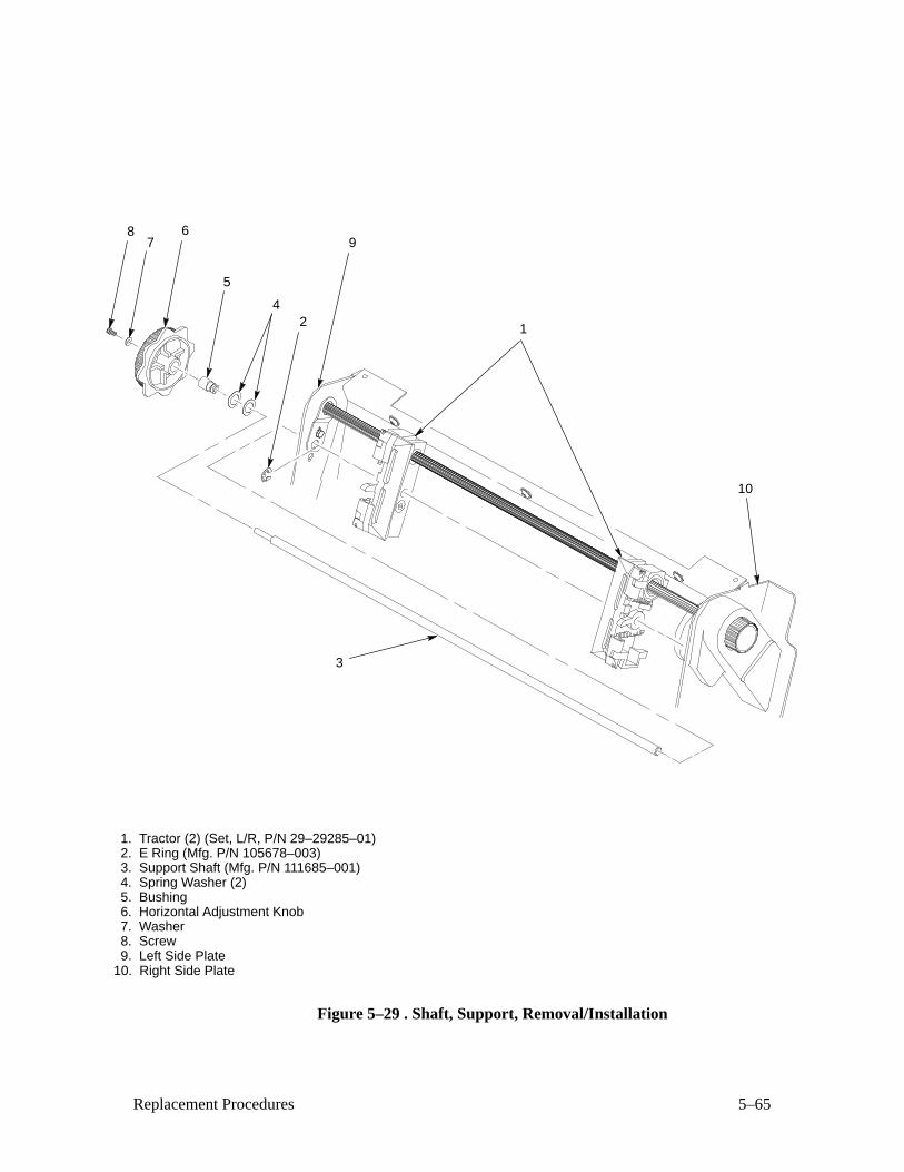
5–65Replacement Procedures
1. Tractor (2) (Set, L/R, P/N 29–29285–01)2. E Ring (Mfg. P/N 105678–003)3. Support Shaft (Mfg. P/N 111685–001)4. Spring Washer (2)5. Bushing6. Horizontal Adjustment Knob7. Washer8. Screw9. Left Side Plate
10. Right Side Plate
3
124
5
67
89
10
Figure 5–29 . Shaft, Support, Removal/Installation

5–66 Replacement Procedures
Shuttle Frame Assembly (Figure 5–30 )
Removal
1. Prepare the printer for maintenance (page 5–3).
2. Remove the shuttle cover assembly (page 5–24).
3. Disconnect the MPU cable connector (1).
4. Disconnect the shuttle motor cable connector (2).
5. Disconnect the shuttle cable assembly connector (3).
CAUTION
The hammer bank flex circuit ribbon cables can tear if handled roughly.Do not pull on the cables; grasp the connectors to disconnect the flexcircuit ribbon cables. In the next step, disconnect the left and right flexribbon connectors gently, and do not bend the cables unnecessarily.
6. Disconnect the left and right hammer bank flex circuit ribbon
connectors (4 and 5).
7. Loosen the side 5/32 inch socket head clamp screws (6) and pull the
clamps (7) back and off the guide shaft (8).
8. Loosen the center 5/32 inch socket head screw (9) enough to release the
shuttle frame assembly (10) from the base casting (11).
9. Slide the last three fingers of your hands under the outer beam standoffs
(12) and hold the ribbon mask in place with you index fingers.
10. Lift the shuttle frame assembly (10) out of the base casting (11). Lift
slowly and carefully: the shuttle frame assembly is heavy.
11. Remove the hammer bank cover (page 5–22).
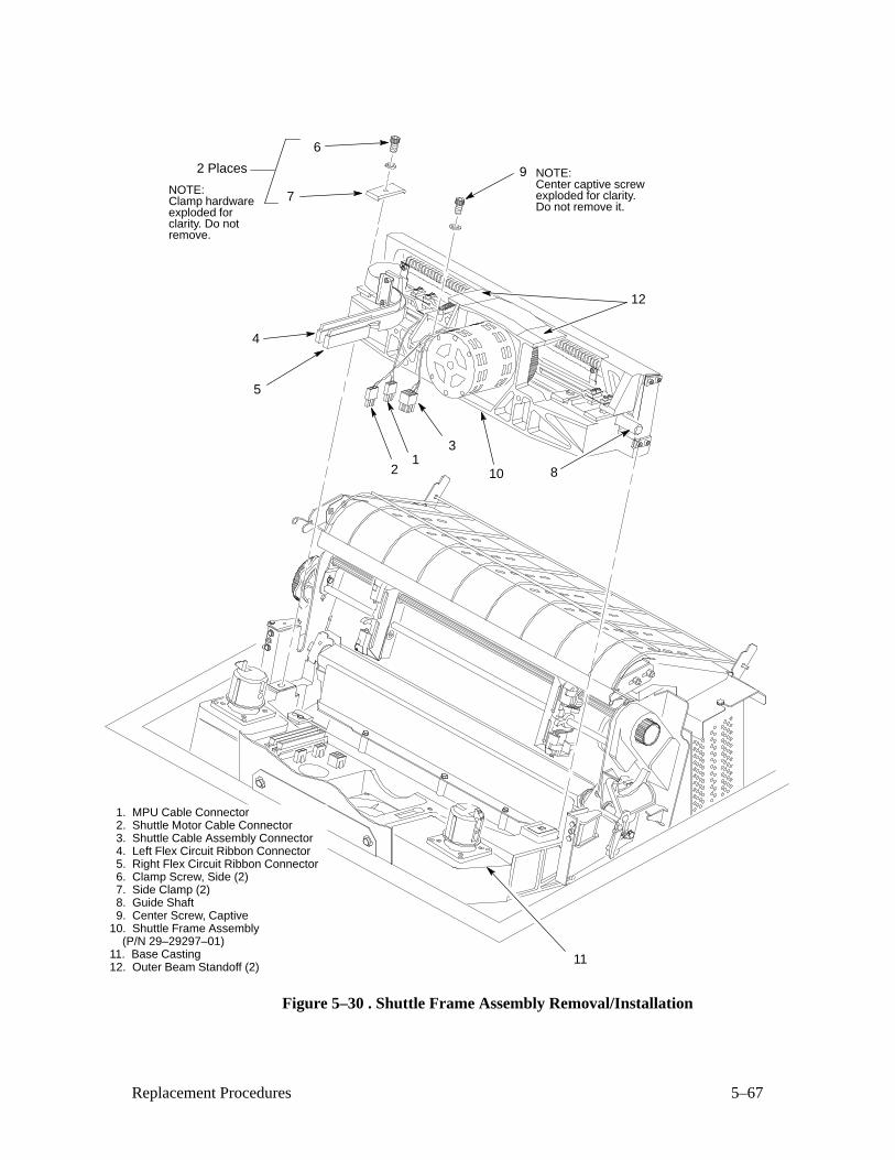
5–67Replacement Procedures
4
5
6
101
3
2 Places
7
9NOTE:Clamp hardwareexploded forclarity. Do notremove.
NOTE:Center captive screwexploded for clarity.Do not remove it.
8
12
2
1. MPU Cable Connector2. Shuttle Motor Cable Connector3. Shuttle Cable Assembly Connector4. Left Flex Circuit Ribbon Connector5. Right Flex Circuit Ribbon Connector6. Clamp Screw, Side (2)7. Side Clamp (2)8. Guide Shaft9. Center Screw, Captive
10. Shuttle Frame Assembly (P/N 29–29297–01)11. Base Casting12. Outer Beam Standoff (2)
11
Figure 5–30 . Shuttle Frame Assembly Removal/Installation
5–68 Replacement Procedures
Installation
1. Install the hammer bank cover (page 5–22).
2. Holding the shuttle frame assembly (10) by the outer beam standoffs
(12), set it into the base casting (11). Use both hands: the shuttle frame
assembly is heavy.
3. Align the center 5/32 inch socket head screw (9) in the base casting (11)
and hand turn the screw until only two or three threads have started.
4. Pull the shuttle frame assembly (10) toward the front of the printer.
5. Slide the side clamps (7) over the guide shaft (8) and torque the
5/32 inch socket head clamp screws (6) to 20 ± 1 inch–pounds.
6. Lift up on the shuttle motor, then gently set it down to align the center
screw guide.
7. Torque the center captive 5/32 inch socket head screw (9) to
20 ± 1 inch–pounds.
8. Connect the left and right hammer bank flex circuit ribbon connectors (4
and 5).
9. Connect the shuttle cable assembly connector (3).
10. Connect the shuttle motor cable connector (2).
11. Connect the MPU cable connector (1).
12. Adjust the platen gap (page 4–18).
13. Install the shuttle cover assembly (page 5–24).
14. Adjust the platen open belt (page 4–8).
15. Return the printer to normal operation (page 5–80).

5–69Replacement Procedures
4
5
6
101
3
2 Places
7
9NOTE:Clamp hardwareexploded forclarity. Do notremove.
NOTE:Center captive screwexploded for clarity.Do not remove it.
8
12
2
11
1. MPU Cable Connector2. Shuttle Motor Cable Connector3. Shuttle Cable Assembly Connector4. Left Flex Circuit Ribbon Connector5. Right Flex Circuit Ribbon Connector6. Clamp Screw, Side (2)7. Side Clamp (2)8. Guide Shaft9. Center Screw, Captive
10. Shuttle Frame Assembly (P/N 29–29297–01)11. Base Casting12. Outer Beam Standoff (2)
Figure 5–30. Shuttle Frame Assembly Removal/Installation
5–70 Replacement Procedures
Spring Assembly, Gas (Figure 5–31 )
Removal
1. Prepare the printer for maintenance (page 5–3).
2. Open the printer cover (1).
3. Open the floor cabinet rear door.
4. Remove two nuts (2) and washers (3).
5. Remove the gas spring assembly (4).
Installation
1. Position the gas spring assembly (4) on the upper and lower brackets (5
and 6).
2. Install two nuts (2) and washers (3).
3. Close the printer cover (1): make sure the cover closes all the way. If
necessary, adjust the position of the stud in the lower bracket to achieve
smooth and complete closure.
4. Return the printer to normal operation (page 5–80).
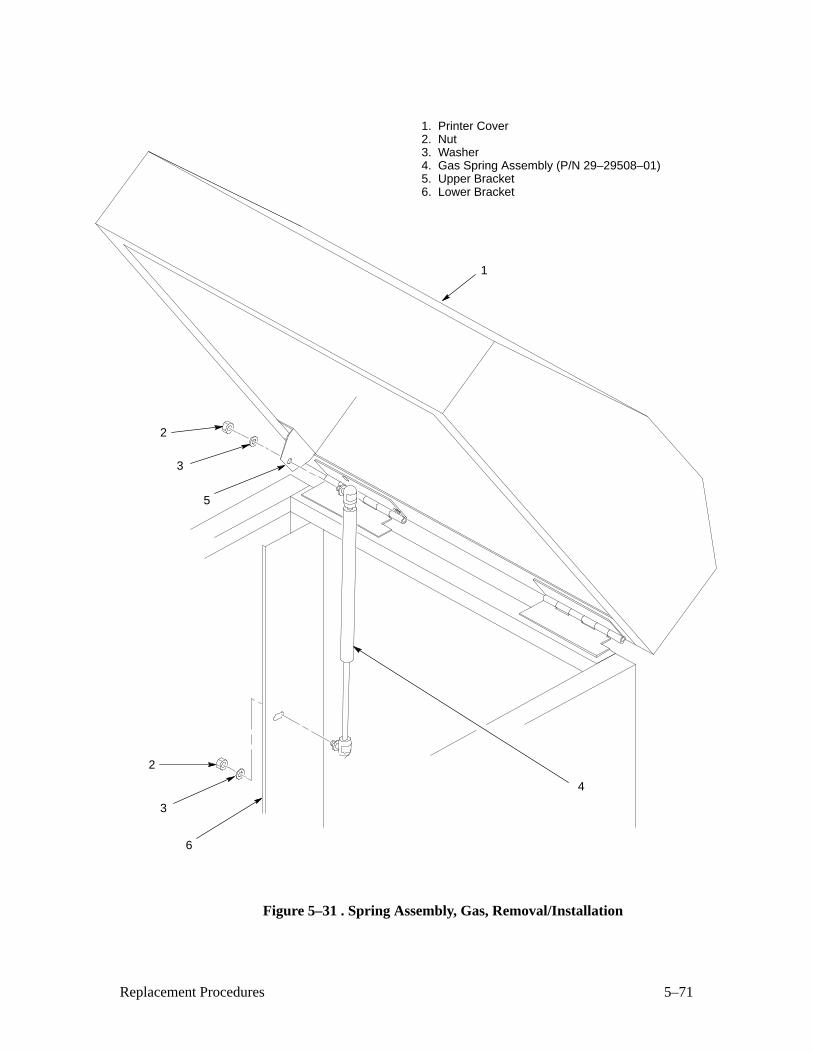
5–71Replacement Procedures
1. Printer Cover2. Nut3. Washer4. Gas Spring Assembly (P/N 29–29508–01)5. Upper Bracket6. Lower Bracket
2
1
4
3
2
3
5
6
Figure 5–31 . Spring Assembly, Gas, Removal/Installation
5–72 Replacement Procedures
Spring, Extension (Figure 5–32 )
Removal
1. Prepare the printer for maintenance (page 5–3).
2. Open the printer cover.
3. Remove the shuttle cover assembly (page 5–24).
4. Unhook the extension spring (1) from the spring lugs (2) on the hammer
bank (3) and shuttle frame (4).
Installation
1. Apply a dab of M–3 lubricant to both spring lugs (2).
2. Hook the extension spring (1) over the spring lugs (2).
3. Install the shuttle cover assembly (page 5–24).
4. Return the printer to normal operation (page 5–80).
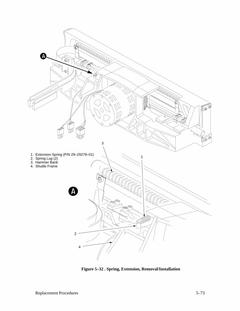
5–73Replacement Procedures
1. Extension Spring (P/N 29–29279–01)2. Spring Lug (2)3. Hammer Bank4. Shuttle Frame
1
3
2
4
Figure 5–32 . Spring, Extension, Removal/Installation
5–74 Replacement Procedures
Switch Assembly, Cover Open (Figure 5–33 )
Removal
1. Prepare the printer for maintenance (page 5–3).
2. Open the printer cover.
3. Remove the shuttle cover assembly (page 5–24).
4. Remove two screws (1) and lift the cover open switch assembly (2) out
of the base casting.
5. Disconnect the switch connectors from intermediate cable assembly
connector CO+ (3) and CO– (4).
Installation
1. Connect the switch connectors to intermediate cable assembly connector
CO+ (3) and CO– (4).
2. Position the cover open switch assembly (2) in the base casting and
install two screws (1).
3. Install the shuttle cover assembly (page 5–24).
4. Return the printer to normal operation (page 5–80).
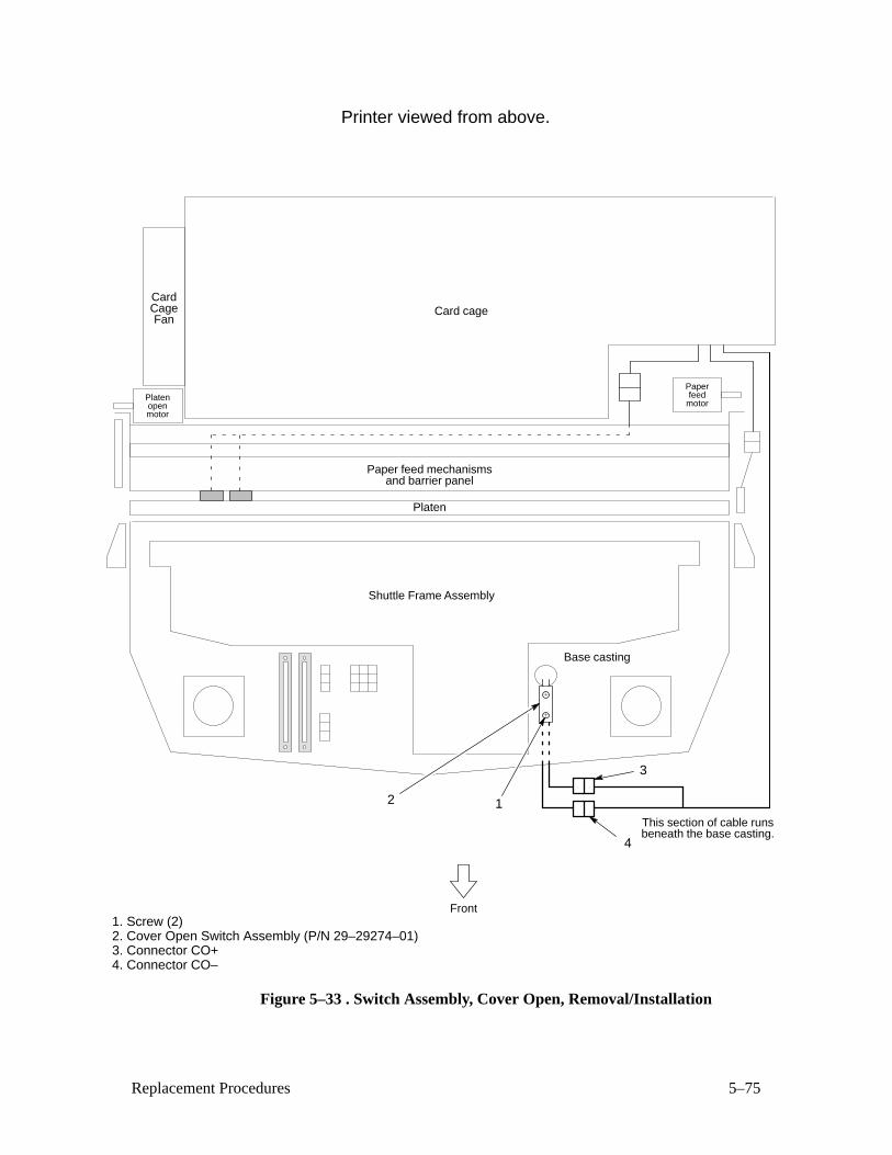
5–75Replacement Procedures
Card cage
Front
Shuttle Frame Assembly
CardCageFan
Paper feed mechanismsand barrier panel
Platen
Base casting
Platenopenmotor
Paperfeed
motor
1. Screw (2) 2. Cover Open Switch Assembly (P/N 29–29274–01)3. Connector CO+4. Connector CO–
3
4
2
This section of cable runsbeneath the base casting.
1
Printer viewed from above.
Figure 5–33 . Switch Assembly, Cover Open, Removal/Installation
5–76 Replacement Procedures
Switch Assembly, Paper Detector (Figure 5–34 )
Removal
1. Prepare the printer for maintenance (page 5–3).
2. Remove the paper guide assembly (page 5–42).
3. Remove four screws (1) and the barrier shield (2).
4. Remove the shuttle frame assembly (page 5–66).
5. Remove the paper ironer (page 5–44).
6. Loosen the screws (3) securing the paper detector switch assembly (4).
7. Disconnect the paper detector switch cable connector (5) from the
intermediate cable assembly connector PMD.
8. Cut the tie wraps securing the switch assembly cable to the front of the
card cage and remove the paper detector switch assembly (4).
Installation
1. Position the paper detector switch assembly (4) and install the screw (3)
securing it to the printer base.
2. Connect the paper detector switch cable connector (5) to theintermediate cable assembly connector PMD.
3. Install tie wraps securing the switch assembly cable to the front of the
card cage.
4. Install the paper ironer (page 5–44).
5. Install the shuttle frame assembly (page 5–66).
6. Install the barrier shield (2) and four screws (1).
7. Install the paper guide assembly (page 5–42).
8. Return the printer to normal operation (page 5–80).
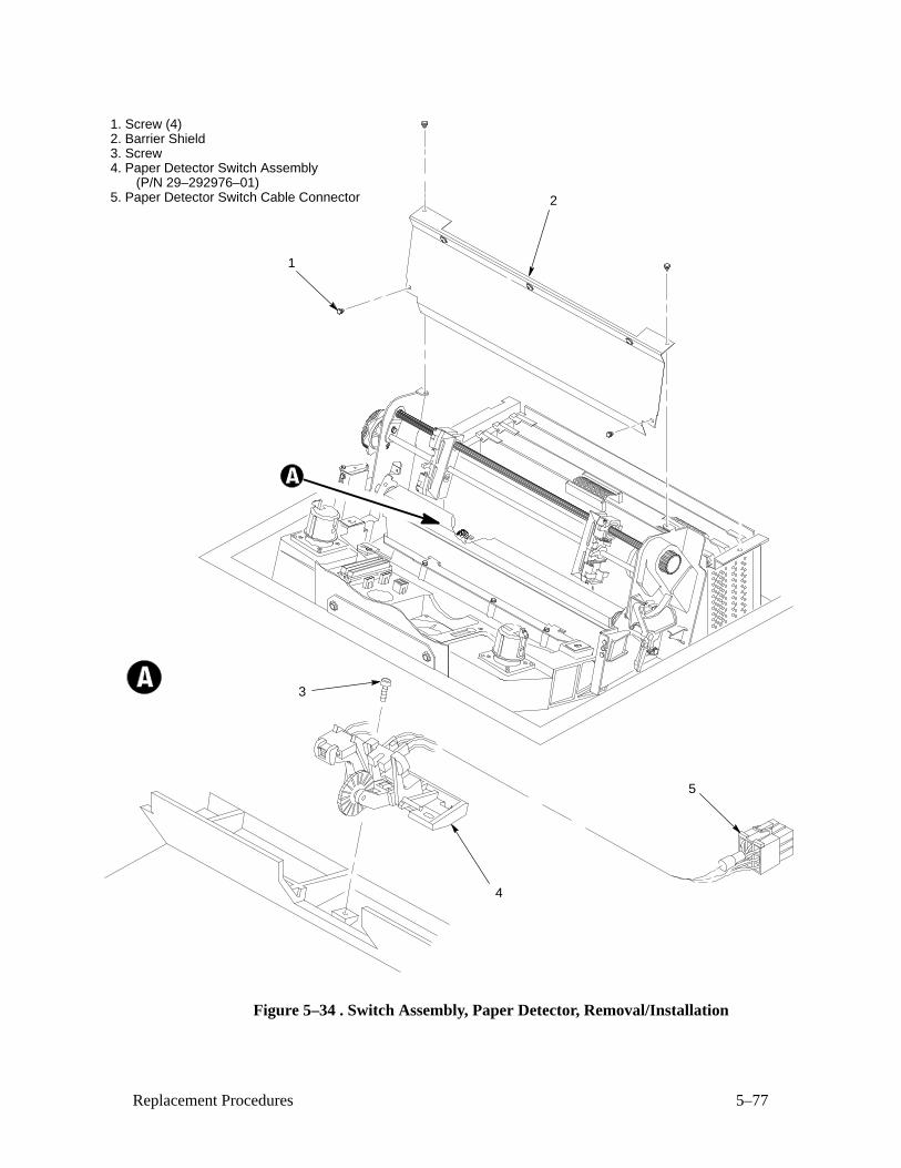
5–77Replacement Procedures
1. Screw (4)2. Barrier Shield3. Screw4. Paper Detector Switch Assembly (P/N 29–292976–01)5. Paper Detector Switch Cable Connector
1
2
4
3
5
Figure 5–34 . Switch Assembly, Paper Detector, Removal/Installation
5–78 Replacement Procedures
Switch Assembly, Platen Interlock (Figure 5–35 )
Removal
1. Prepare the printer for maintenance (page 5–3).
2. Open the printer cover.
3. Disconnect the platen interlock switch connector (1) from connector
P1(P) (2).
4. Fully close the forms thickness lever (3).
5. Remove two screws (4).
6. Remove the platen interlock switch assembly (5) from the forms
thickness indicator plate (6).
Installation
1. Fully close the forms thickness lever (3).
2. Position the platen interlock switch assembly (5) on the forms thickness
indicator plate (6).
3. Install two screws (4).
4. Connect the platen interlock switch connector (1) to connector P1(P)(2).
5. Return the printer to normal operation (page 5–80).
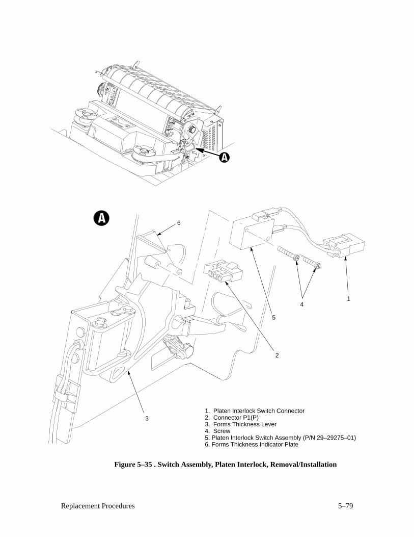
5–79Replacement Procedures
1. Platen Interlock Switch Connector2. Connector P1(P)3. Forms Thickness Lever4. Screw5. Platen Interlock Switch Assembly (P/N 29–29275–01)6. Forms Thickness Indicator Plate
2
3
4
5
6
1
Figure 5–35 . Switch Assembly, Platen Interlock, Removal/Installation
5–80 Replacement Procedures
Tractor (L/R)
Removal
1. Prepare the printer for maintenance (page 5–3).
2. Remove the splined shaft (page 5–62).
3. Remove the support shaft (page 5–64).
4. Remove the tractors from the support shaft.
Installation
1. Using the replacement tractors, install the support shaft (page 5–64).
2. Install the splined shaft (page 5–62).
3. Return the printer to normal operation (see below).
Returning the Printer to Normal Operation
1. Load paper.
2. Install the ribbon.
3. Close floor cabinet doors and the printer cover.
4. Connect the ac power cord to the power source and the printer.
5. Set the power switch to 1 (on).
6. Test printer operation by selecting and running one of the diagnostic
self–tests (page 3–26).
A–1Printer Configuration
A Printer Configuration
Contents
Printer Configuration A–2. . . . . . . . . . . . . . . . . . . . . . . . . . . . . . . . . . . . . . . . . . . . .
Configuration Printout A–2. . . . . . . . . . . . . . . . . . . . . . . . . . . . . . . . . . . . . . . . . . . .
Configuration Procedure A–3. . . . . . . . . . . . . . . . . . . . . . . . . . . . . . . . . . . . . . . . . .
Saving Configuration Values A–4. . . . . . . . . . . . . . . . . . . . . . . . . . . . . . . . . . . . . . .
Loading Configuration Values A–5. . . . . . . . . . . . . . . . . . . . . . . . . . . . . . . . . . . . . .
Changing Printer Emulations A–6. . . . . . . . . . . . . . . . . . . . . . . . . . . . . . . . . . . . . .
Configuration Diagram A–7. . . . . . . . . . . . . . . . . . . . . . . . . . . . . . . . . . . . . . . . . . .
A–2 Printer Configuration
Printer Configuration
IMPORTANT
Configuration directly affects printer operation. Do not change printerconfiguration until you are thoroughly familiar with the procedures inthis appendix.
Configuration refers to the operating properties that define how the printer
responds to signals and commands received from the host computer. These
properties, called configuration parameters, are set to match the operating
characteristics of the host computer system.
You can set some configuration parameters either by a control code from the
host computer or at the operator control panel. In such cases, a command
from the host overrides the control panel selection. (If you save configurationvalues after such an override, the data stream control code value is saved
instead of the value you selected at the control panel.)
Configuration Printout
The configuration printout lists the configuration parameters currently in use.
When you exit configuration printout mode, the printer restores the previous
font and line spacing (lpi) and all character attributes are canceled. All other
format parameters remain unaffected.
To obtain a configuration printout:
1. Press the ON LINE switch to place the printer off–line.
2. Open the printer cover.
3. Press NEXT until “Off–Line/Print Config” appears on the message
display.
4. Press the R/S (Run/Stop) switch. The configuration listing prints.
5. Press CLEAR and close the printer cover.
6. Press the ON LINE switch to place the printer on–line.
A–3Printer Configuration
Configuration Procedure
Use the following procedure to configure the printer from the control panel:
1. Obtain a configuration printout (page A–2).
2. Determine the parameter values that must be changed to meet your
requirements.
3. Take the printer off–line by pressing the ON LINE switch.
4. Open the printer cover.
NOTE: You must unlock the ENTER switch to change a configuration
value. If you leave the ENTER switch locked you can examine — but
not change — the current configuration.
5. Press UP and DOWN simultaneously to unlock the ENTER switch.
“Unlocked” appears briefly on the message display.
6. Locate the desired menu by pressing DOWN and then NEXT or PREV
until the menu name appears on the display. Use the Configuration
Diagram (page A–7) as your “road map.”
7. Locate the desired value in a menu by pressing DOWN, then pressing
NEXT or PREV until the desired value appears on the display.
8. Press ENTER when the desired value is showing on the message
display.
9. Press UP, then NEXT or PREV to move to the next desired menu.
Repeat steps 7 and 8.
10. After you have made all required parameter changes, press CLEAR. The
display goes to “Off–Line/Emulation.” Press NEXT until
“Off–Line/Save Config” displays. Press ENTER. This saves the
parameter values as the power–up default values.
11. Lock the ENTER switch by pressing UP and DOWN simultaneously.
“Locked” appears briefly on the message display.
12. Close the printer cover. Place the printer on–line by pressing ON LINE.
Your selected values are now active.
A–4 Printer Configuration
Saving Configuration Values
When you save a set of configuration values they become active every time
the printer is turned on.
To save a set of configuration values:
1. Press the ON LINE switch to take the printer off–line.
“Off–Line/Emulation” appears on the message display.
2. Open the printer cover.
3. Press UP and DOWN simultaneously to unlock the ENTER switch.
“Unlocked” appears briefly on the message display.
4. Press NEXT (or PREV) until “Off–Line/Save Config” appears on the
display.
5. Press ENTER.
The printer saves the parameters in nonvolatile memory then displays
“Done.”
6. Press CLEAR to return to “Off–Line/Emulation” display.
7. Press UP and DOWN simultaneously to lock the ENTER switch.
“Locked” appears briefly on the message display.
8. Close the printer cover.
9. Press the ON LINE switch to place the printer on–line.

A–5Printer Configuration
Loading Configuration Values
Configuration values saved using the “Save Config” menu (page A–4)
become the power–up default configuration. The set of factory values
remains permanently stored in printer memory, however.
The “Load Config” menu gives you the choice of loading either the saved or
the factory configuration values.
NOTE: If you have not saved a set of configuration values, this procedure
loads the factory value set.
To load a set of configuration values:
1. Press the ON LINE switch to take the printer off–line.
“Off–Line/Emulation” appears on the message display.
2. Open the printer cover.
3. Press UP and DOWN simultaneously to unlock the ENTER switch.
“Unlocked” appears briefly on the message display.
4. Press NEXT or PREV until “Off–Line/Load” appears on the display.
5. Press DOWN, then press NEXT or PREV to select either “Load/Saved”
or “Load/Factory”.
6. Press ENTER when the desired selection displays.
The printer loads the parameters then displays “Done”.
7. Press CLEAR to return to “Off–Line/Emulation”.
8. Press UP and DOWN simultaneously to lock the ENTER switch.
“Locked” appears briefly on the message display.
9. Close the printer cover.
10. Press the ON LINE switch to place the printer on–line.
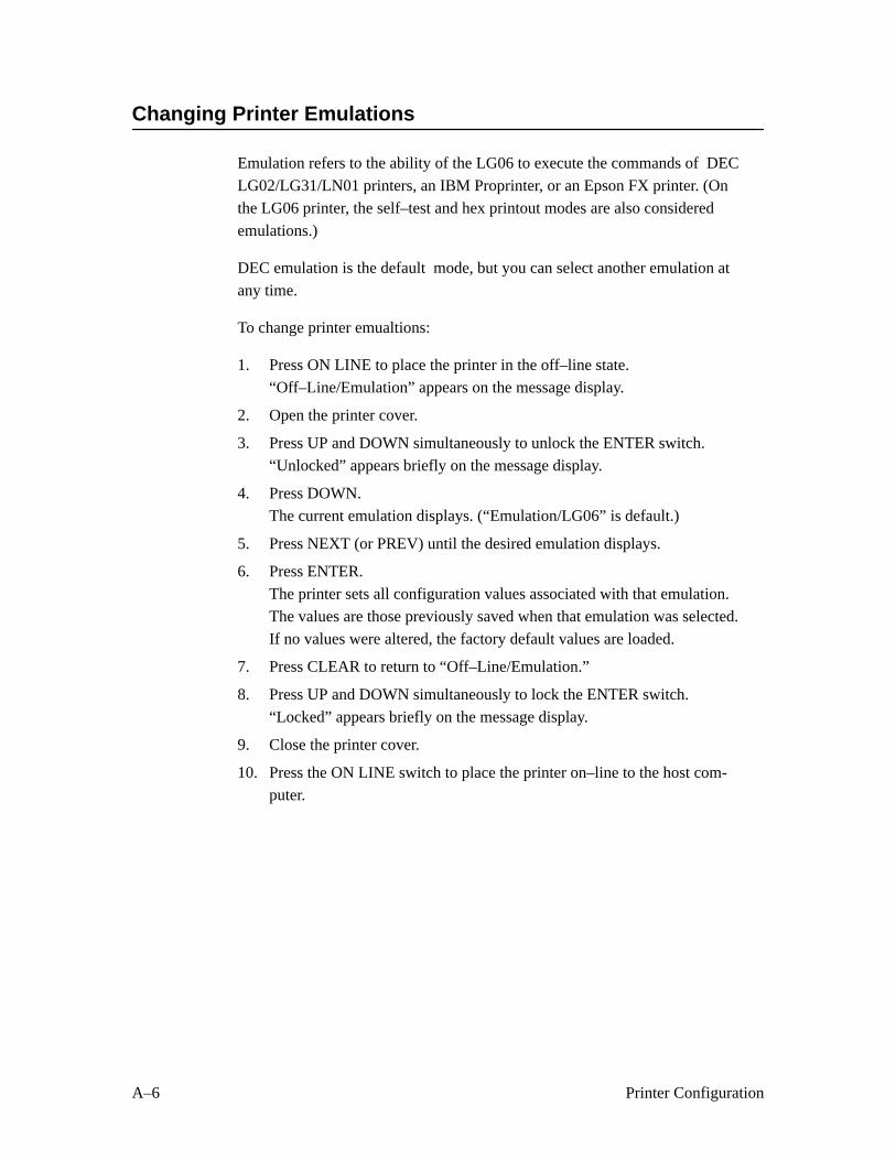
A–6 Printer Configuration
Changing Printer Emulations
Emulation refers to the ability of the LG06 to execute the commands of DEC
LG02/LG31/LN01 printers, an IBM Proprinter, or an Epson FX printer. (On
the LG06 printer, the self–test and hex printout modes are also considered
emulations.)
DEC emulation is the default mode, but you can select another emulation at
any time.
To change printer emualtions:
1. Press ON LINE to place the printer in the off–line state.
“Off–Line/Emulation” appears on the message display.
2. Open the printer cover.
3. Press UP and DOWN simultaneously to unlock the ENTER switch.
“Unlocked” appears briefly on the message display.
4. Press DOWN.
The current emulation displays. (“Emulation/LG06” is default.)
5. Press NEXT (or PREV) until the desired emulation displays.
6. Press ENTER.
The printer sets all configuration values associated with that emulation.
The values are those previously saved when that emulation was selected.
If no values were altered, the factory default values are loaded.
7. Press CLEAR to return to “Off–Line/Emulation.”
8. Press UP and DOWN simultaneously to lock the ENTER switch.
“Locked” appears briefly on the message display.
9. Close the printer cover.
10. Press the ON LINE switch to place the printer on–line to the host com-puter.
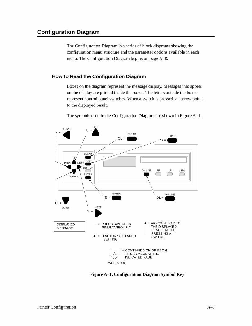
A–7Printer Configuration
Configuration Diagram
The Configuration Diagram is a series of block diagrams showing the
configuration menu structure and the parameter options available in each
menu. The Configuration Diagram begins on page A–8.
How to Read the Configuration Diagram
Boxes on the diagram represent the message display. Messages that appear
on the display are printed inside the boxes. The letters outside the boxesrepresent control panel switches. When a switch is pressed, an arrow points
to the displayed result.
The symbols used in the Configuration Diagram are shown in Figure A–1.
DISPLAYEDMESSAGE
CL =
D =
U =
N =
P =
+ = PRESS SWITCHES SIMULTANEOUSLY
= ARROWS LEAD TOTHE DISPLAYEDRESULT AFTERPRESSING ASWITCH
OL =E =
FACTORY (DEFAULT)SETTING
=
A= CONTINUED ON OR FROM
THIS SYMBOL AT THEINDICATED PAGE
ON LINE
CLEAR
DOWN
UP
NEXT
PREV
ENTER
PAGE A–XX
*
ON LINE FF VIEW
ENTER
CLEAR
R/S
SET TOFLF
NEXTPREV
DOWN
UP
RS =R/S
Figure A–1. Configuration Diagram Symbol Key
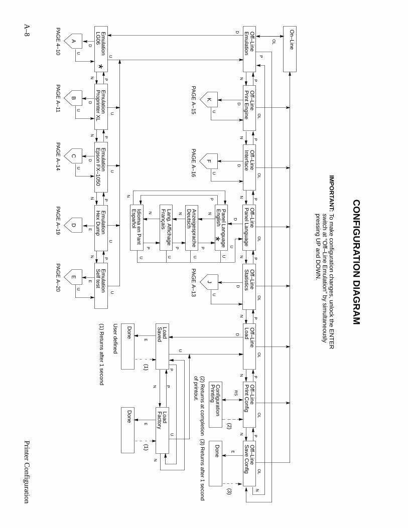
A–8
Printer C
onfiguration
On–Line
OL
LoadD
D
U
OL
OL
OL
K
IMP
OR
TAN
T:
Save C
onfig OL
J
Done
E(3)
PND
U OL
F(3) R
eturns after 1 second
CO
NF
IGU
RAT
ION
DIA
GR
AM
PA
GE
A–13
PA
GE
A–16
PA
GE
A–15
PN
PN
PN
PN
Off–Line
Off–Line
Off–Line
Off–Line
Off–Line
Off–Line
OL
RS
Print C
onfig
Configuration
Printing
(2) Returns at com
pletionof printout.
(2)
Off–Line
PN
U
Em
ulation P
rint Engine
D
P
SavedE
Done
(1)
User defined
Load
U
Factory
E
Done
(1)
Load
NN
P
(1) Returns after 1 second
U
Statistics
Interface
PN
U
DEm
ulationE
mulation
LG06
Proprinter X
L
PN
D
UA
PA
GE
4–10
D
UB
PA
GE
A–11
U
*
OL
PN
Off–Line
Panel Language
Panel Language
English
Anzeigesprache
Deutsch
DUP
N
N
P
Lang. Affichage
Idioma en P
ant
UUUU
PN
PN
*
Français
Español
PN
U
Em
ulationE
mulation
Hex D
ump
Self test
E
D
PA
GE
A–19
E
UE
PA
GE
A–20
U
PN
Em
ulationE
pson FX
–1050 D
UC
PA
GE
A–14
U
PN
To make configuration changes, unlock the E
NT
ER
switch at “O
ff–Line Em
ulation” by simultaneously
pressing UP
and DO
WN
.
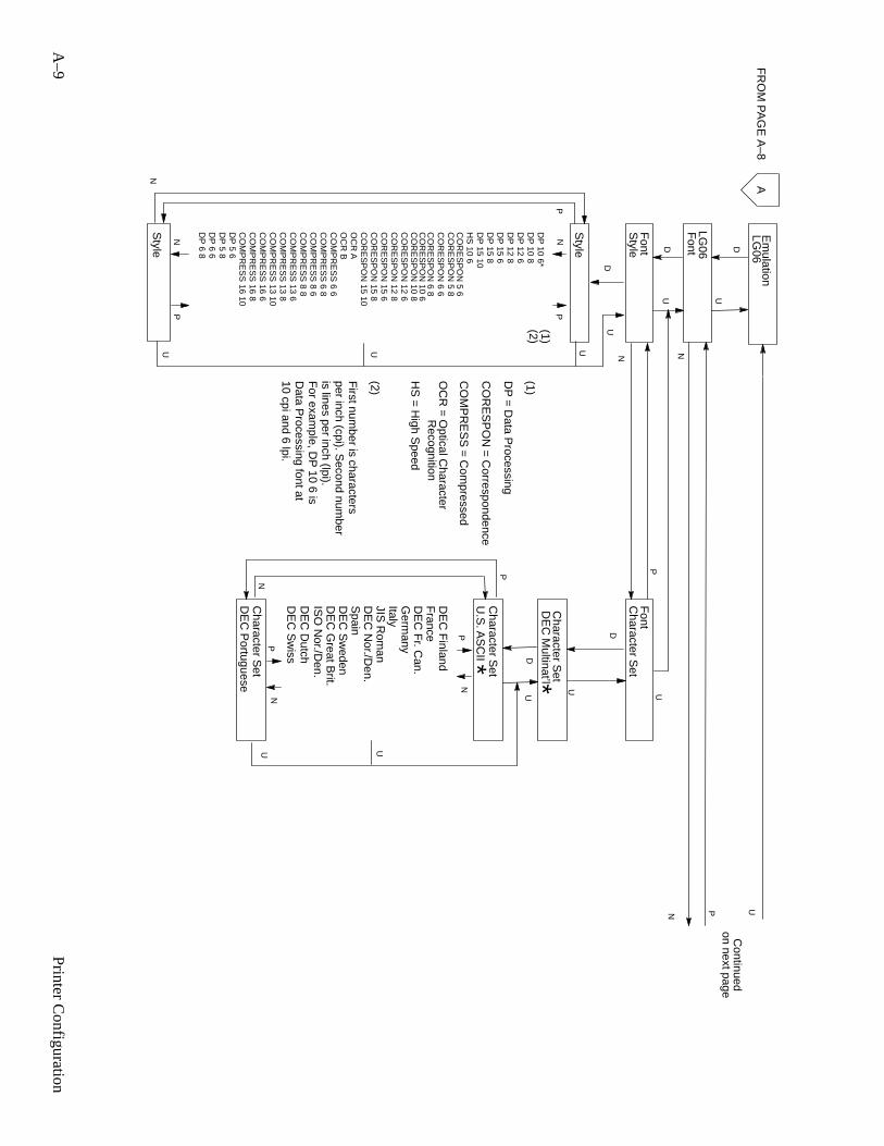
A–9
Printer C
onfiguration
A
UU U
LG06
Font
P
D
N
Font
Character S
et
DE
C M
ultinat’l
DE
C N
or./Den.
JIS R
oman
Italy
Spain
DE
C G
reat Brit.
Germ
any
DE
C S
weden
DE
C F
r. Can.
ISO
Nor./D
en.
DE
C F
inlandF
rance
Character S
et
DU
Character S
et
NP
P
N
D
U
P
Em
ulation F
RO
M P
AG
E A
–8LG
06
Style
DU
PN
N
P
Style
UUP
N
DE
C D
utchD
EC
Sw
iss
DE
C P
ortuguese
Continued
on next page
U
Font
Style D
N
(1)(1)
DP
= D
ata Processing
CO
RE
SP
ON
= C
orrespondence
CO
MP
RE
SS
= C
ompressed
OC
R =
Optical C
haracterR
ecognition
(2)
(2)
First num
ber is charactersper inch (cpi). S
econd number
is lines per inch (lpi).F
or example, D
P 10 6 is
Data P
rocessing font at10 cpi and 6 lpi.
DP
10 6*D
P 10 8
DP
12 6D
P 12 8
DP
15 6D
P 15 8
DP
15 10H
S 10 6
HS
= H
igh Speed
CO
RE
SP
ON
5 6C
OR
ES
PO
N 5 8
CO
RE
SP
ON
6 6C
OR
ES
PO
N 6 8
CO
RE
SP
ON
12 6C
OR
ES
PO
N 12 8
CO
RE
SP
ON
15 6C
OR
ES
PO
N 15 8
CO
RE
SP
ON
15 10O
CR
AO
CR
BC
OM
PR
ES
S 6 6
CO
MP
RE
SS
6 8C
OM
PR
ES
S 8 6
CO
MP
RE
SS
8 8C
OM
PR
ES
S 13 6
CO
MP
RE
SS
13 8C
OM
PR
ES
S 13 10
CO
MP
RE
SS
16 6C
OM
PR
ES
S 16 8
CO
MP
RE
SS
16 10D
P 5 6
DP
5 8D
P 6 6
DP
6 8
*
U.S
. AS
CII
Character S
et
*N
P
U
UU
N
CO
RE
SP
ON
10 6C
OR
ES
PO
N 10 8
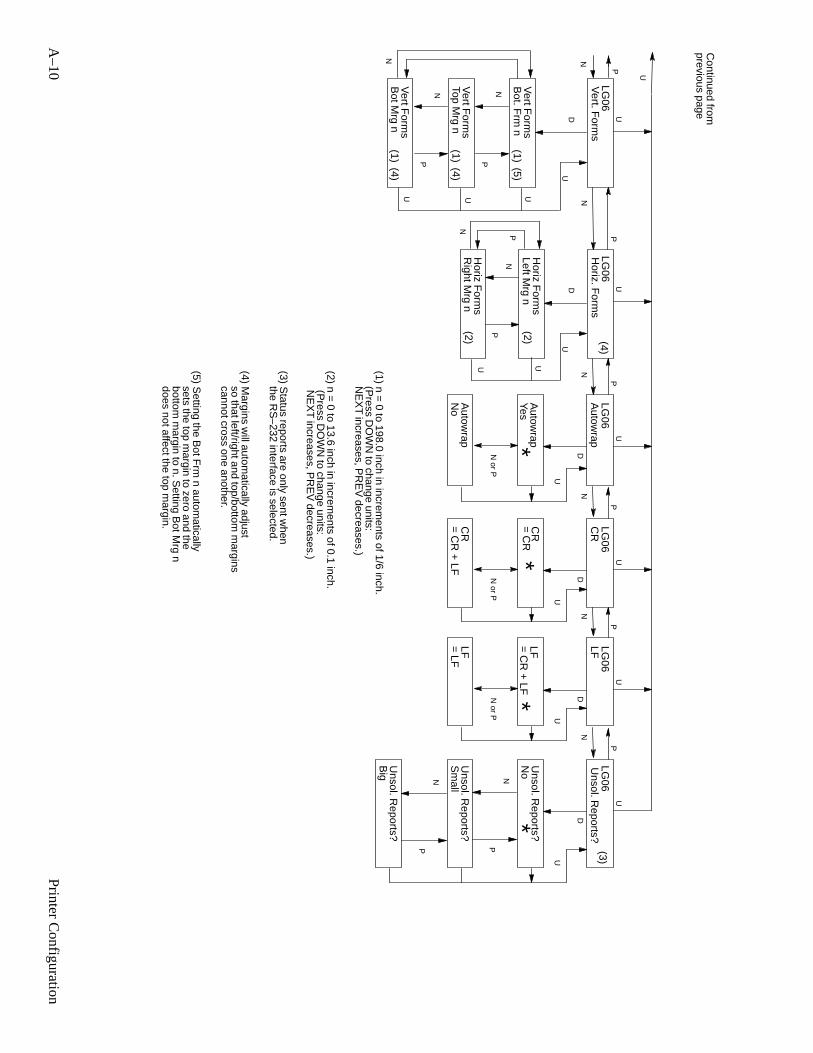
A–10
Printer C
onfiguration
UU
LG06
PP
NN
Vert. F
orms
Horiz F
orms
Left Mrg n
Right M
rg n
DU
P
N
N
P
UU
LG06
Horiz. F
orms
DU
N
Vert F
orms
Bot M
rg n
Vert F
orms
Bot. F
rm n
Vert F
orms
Top Mrg n
UUU
P
N
P
N
Continued from
previous page
U
DN or P
Autow
rap
Yes
No
Autow
rap
Autow
rap
U
*
LG06
UP
NDN
or P
CR
= C
R
= C
R +
LFC
R
U
*
LG06
UP
NDN
or P
LF= C
R +
LF
= LF
LF LF
U
*
LG06
UU
P
ND
Unsol. R
eports?
U
*
LG06
N
P
(1)
(1)
(1)
(1) n = 0 to 198.0 inch in increm
ents of 1/6 inch.
(2) n = 0 to 13.6 inch in increm
ents of 0.1 inch.
(2)
(2)H
oriz Form
s
CR
No
Sm
all
Big
(4)
(3) Status reports are only sent w
henthe R
S–232 interface is selected.
(4) Margins w
ill automatically adjust
so that left/right and top/bottom m
arginscannot cross one another.
(4)(3)
Unsol. R
eports?
Unsol. R
eports?
Unsol. R
eports?
P
N
P
N
(4)
(5)
(5) Setting the B
ot Frm
n automatically
sets the top margin to zero and the
(Press D
OW
N to change units:
NE
XT
increases, PR
EV
decreases.)
(Press D
OW
N to change units:
NE
XT
increases, PR
EV
decreases.)
bottom m
argin to n. Setting B
ot Mrg n
does not affect the top margin.
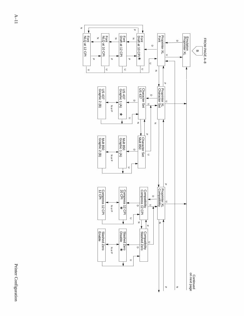
A–11
Printer C
onfiguration
B
UU
Proprinter X
LP
roprinter XL
D
P
NF
ontC
haracter Set
P
Em
ulation
FR
OM
PA
GE
A–8
Proprinter X
L
Font
Draft at 10 C
PI
Font
Draft at 12 C
PI
DU
P
N
N
P*
Font
NLQ
at 10 CP
I
Font
NLQ
at 12 CP
I
UUUU
P
N
P
N
U
Continued
on next page
N
Character S
etU
S 437
Graphic 2 (B
)U
S 437
D
*G
raphic 1 (A)
US
437
Graphic 2 (B
)M
ult 850 D
Graphic 1 (A
)M
ult 850
Character S
etM
ult 850N
P
DU
U
Proprinter X
LC
ompatibility
ND
UDN or P
Com
press 12 CP
I
20 CP
I
12 CP
IC
ompress 12 C
PI
Com
press 12 CP
I
U
*
UP
NDN
or P
Slashed Z
ero
Enable
Disable
Slashed Z
ero
Slashed Z
ero
U
*
Com
patibility C
ompatibility
P
N
N or P
N or P
UU
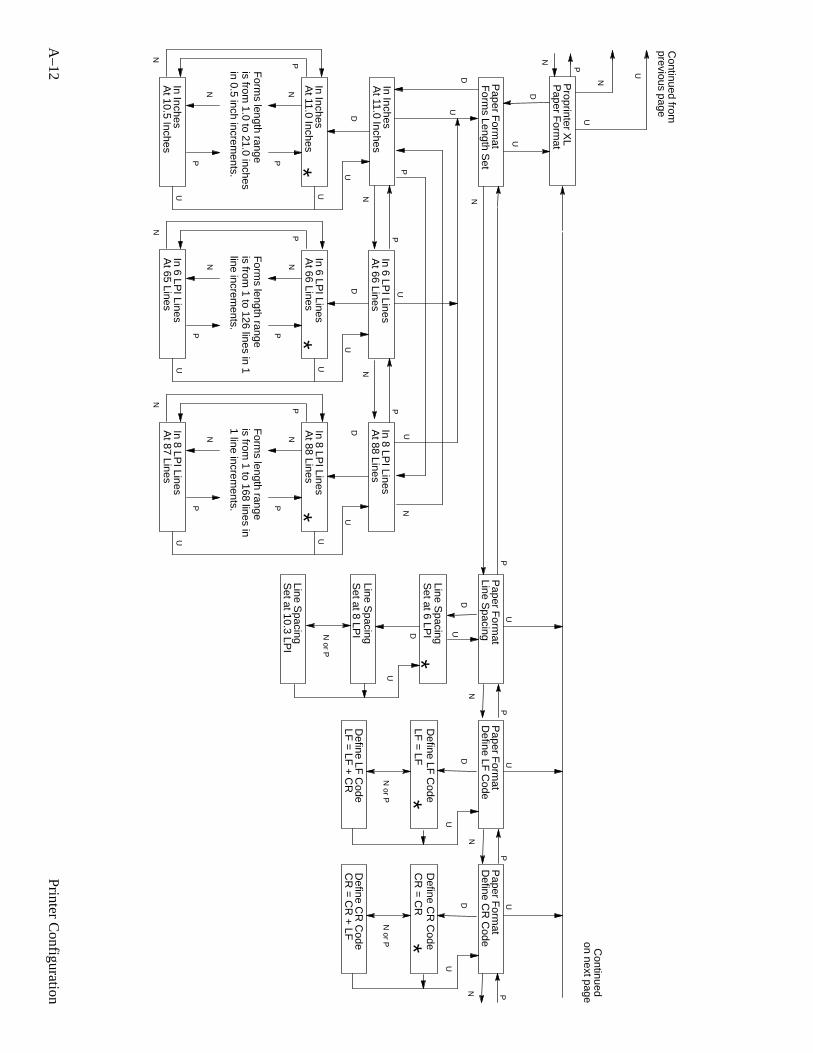
A–12
Printer C
onfiguration
Proprinter X
LP
aper Form
at
In InchesA
t 11.0 Inches
DU
P
N
N
P*
U
In InchesA
t 10.5 InchesU
P
N
Continued from
previous page
U
U
N
N
P
U
U
P
N
UP
N
Form
s length rangeis from
1.0 to 21.0 inchesin 0.5 inch increm
ents.
In 6 LPI Lines
At 66 Lines
DU
P
N
N
P*
U
In 6 LPI Lines
At 65 Lines
U
P
N
Form
s length rangeis from
1 to 126 lines in 1line increm
ents.
In 8 LPI Lines
At 88 Lines
DU
P
N
N
P*
U
In 8 LPI Lines
At 87 Lines
U
P
N
Form
s length rangeis from
1 to 168 lines in1 line increm
ents.
U
Paper F
ormat
Paper F
ormat
P
NF
orms Length S
etLine S
pacingN
NP
D
U
D
DUDN
or P
Set at 6 LP
I
Set at 8 LP
I
Set at 10.3 LP
ILine S
pacing
Line Spacing
U
*Line S
pacing
U
Paper F
ormat
Define LF
Code
ND
N or P
LF =
LF +
CR
LF =
LF
Define LF
Code
Define LF
Code
U
PU
Paper F
ormat
Define C
R C
ode
D
N or P
CR
= C
R
CR
= C
R +
LFD
efine CR
Code *
U
Define C
R C
ode
P
N P
Continued
on next page
*In InchesA
t 11.0 InchesIn 6 LP
I LinesA
t 66 LinesIn 8 LP
I LinesA
t 88 Lines
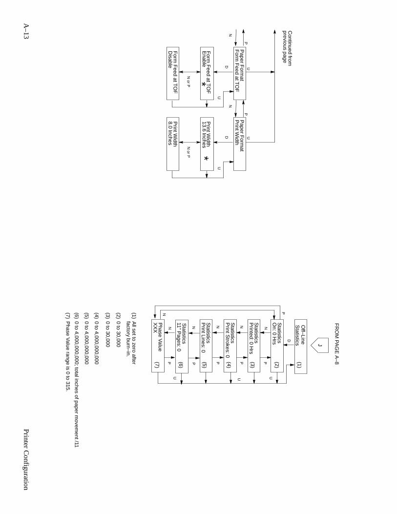
A–13
Printer C
onfiguration
Continued from
previous page
N
U
Paper F
ormat
Form
Feed at T
OF
ND
N or P
Enable
Disable
Form
Feed at T
OF
*F
orm F
eed at TO
F
U
PU
Paper F
ormat
Print W
idth
D
N or P
13.6 Inches
8.0 InchesP
rint Width
*
U
Print W
idth
P
Statistics
Off–Line
On: 0 H
rs
Printed: 0 H
rs
Print S
trokes: 0
NN
PP
D
P
U
N
U
Print Lines: 0
XX
X NP
U
NP
Statistics
Statistics
Statistics
Statistics
Phase V
alue
(1)
(1)A
ll set to zero afterfactory burn–in.
(2)
(3)
(4)
(5)
(7)
(2)0 to 30,000
(3)0 to 30,000
(4)0 to 4,000,000,000
(5)0 to 4,000,000,000
(6)0 to 4,000,000,000; total inches of paper m
ovement /11
J
FR
OM
PA
GE
A–8
NP
Statistics
11” Pages: 0
(6)
(7)P
hase Value range is 0 to 315.
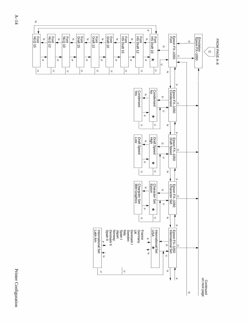
A–14
Printer C
onfiguration
C
UU
Epson F
X–1050
Epson F
X–1050
D
P
NF
ontC
ondensed
Em
ulation
FR
OM
PA
GE
A–8
Epson F
X–1050
Font
HS
Draft 10
Font
HS
Draft 12
DU
PN
N
P*
Font
HS
Draft 15
Font
Draft 10
UUUU
Continued
on next page
N
Condensed
No
*
YesC
ondensed
DU
PN
PN
Font
Draft 12
Font
Draft 15
UU
PN
PN
Font
NLQ
10U
PN
Font
NLQ
12
Font
NLQ
15
UU
PN
PN
PN
UU
U
Epson F
X–1050
Draft S
peed
Draft S
peedH
igh*
LowD
raft Speed
DU
PN
UU
P
N
U
Epson F
X–1050
Character S
et
Character S
etE
pson*
IBM
Graphics
Character S
et
DU
PN
UU
P
N
Epson F
X–1050
International Set
Spain I
ItalyS
weden
Japan
Denm
ark II
Denm
ark I
Norw
ay
UK
Spain II
France
Germ
any
DU
International Set
NP
Latin Am
US
AInternational S
et
*N
P
U U
P
N
UP
N
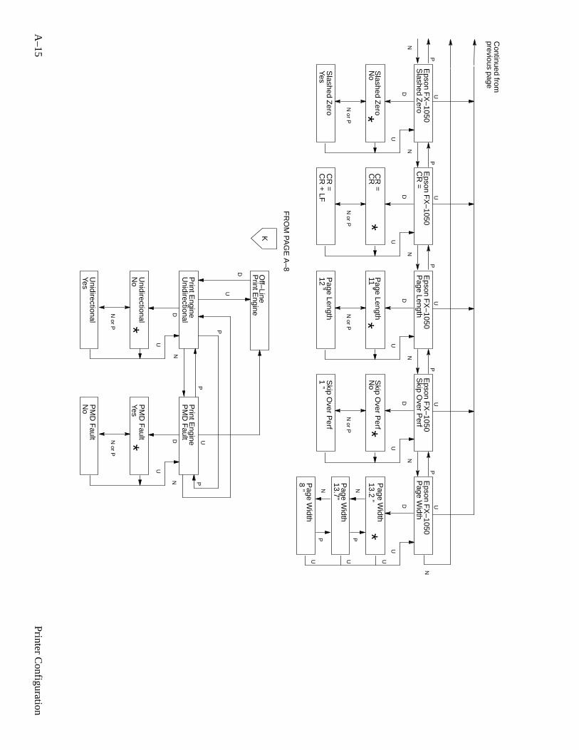
A–15
Printer C
onfiguration
FR
OM
PA
GE
A–8
U
D
KO
ff–Line
DN or P
Unidirectional
No
YesU
nidirectional
Unidirectional
U
*
DN or P
PM
D F
ault
Yes
PM
D F
ault
PM
D F
ault
U
* U
No
P
P
N
PN
Print E
ngine P
rint Engine
Print E
ngine
Continued from
previous page
N
U
Epson F
X–1050
Slashed Z
eroN
D
N or P
No
YesS
lashed Zero *
Slashed Z
ero
U
PU
Epson F
X–1050
CR
=
D
N or P
CR
CR
+ LF
CR
=
*
U
CR
=
P
N
U
Epson F
X–1050
Page Length
ND
N or P
11 ”
12 ”P
age Length *P
age Length
U
PU
Epson F
X–1050
Skip O
ver Perf
D
N or P
No
1 ”S
kip Over P
erf *
U
Skip O
ver Perf
P
N
U
Epson F
X–1050
Page W
idth
D
13.2 ”
13.7”P
age Width
*
U
Page W
idth
PN
PN
8 ”P
age Width
PN
U U U
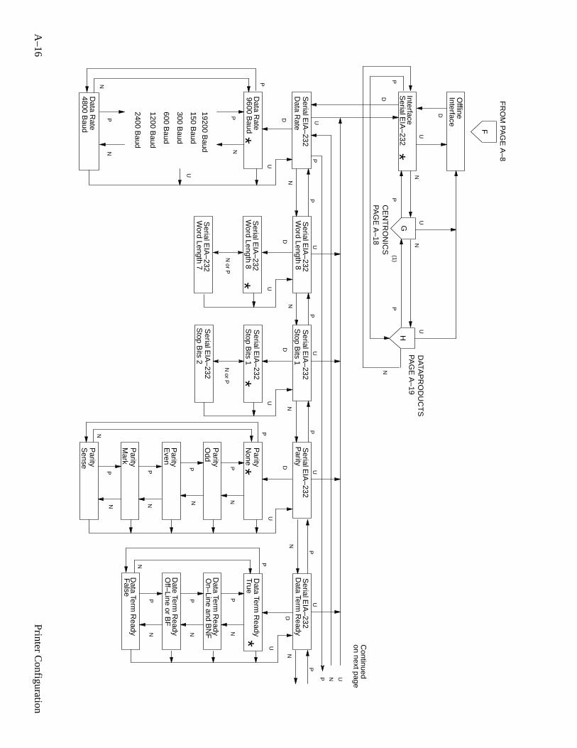
A–16
Printer C
onfiguration
CE
NT
RO
NIC
S
F
D
G
DA
TAP
RO
DU
CT
SU
UU
NN
N
PP
PH
(1)
Interface
FR
OM
PA
GE
A–8
PA
GE
A–18
PA
GE
A–19
Offline
D
PP
PP
N or P
N or P
Serial E
IA–232
PN
PN
PN
PN
P
Data R
ate
9600 Baud
Word Length 8
Data R
ate
Data R
ate4800 B
aud
Stop B
its 1P
arity
Parity
Parity
Parity
None
Odd
Even
Continued
on next page
P
PU
UU
U
U
NN
NN
N
DD
D
UU
UU
*PN
N
**
*
D
Interface
*
PN
PN
Parity
Parity
Mark
Sense
19200 Baud
150 Baud
300 Baud
600 Baud
1200 Baud
2400 Baud
U
U
Data Term
Ready
D
PN
PN
PN
P
Data Term
Ready
Date Term
Ready
Data Term
Ready
Data Term
Ready
False
True
U
N
*
N
P
On–Line and B
NF
Off–Line or B
F
Serial E
IA–232
Serial E
IA–232
Serial E
IA–232
Serial E
IA–232
Serial E
IA–232
Word Length 8
Serial E
IA–232
Word Length 7
Serial E
IA–232
Stop B
its 1S
erial EIA
–232
Stop B
its 2S
erial EIA
–232
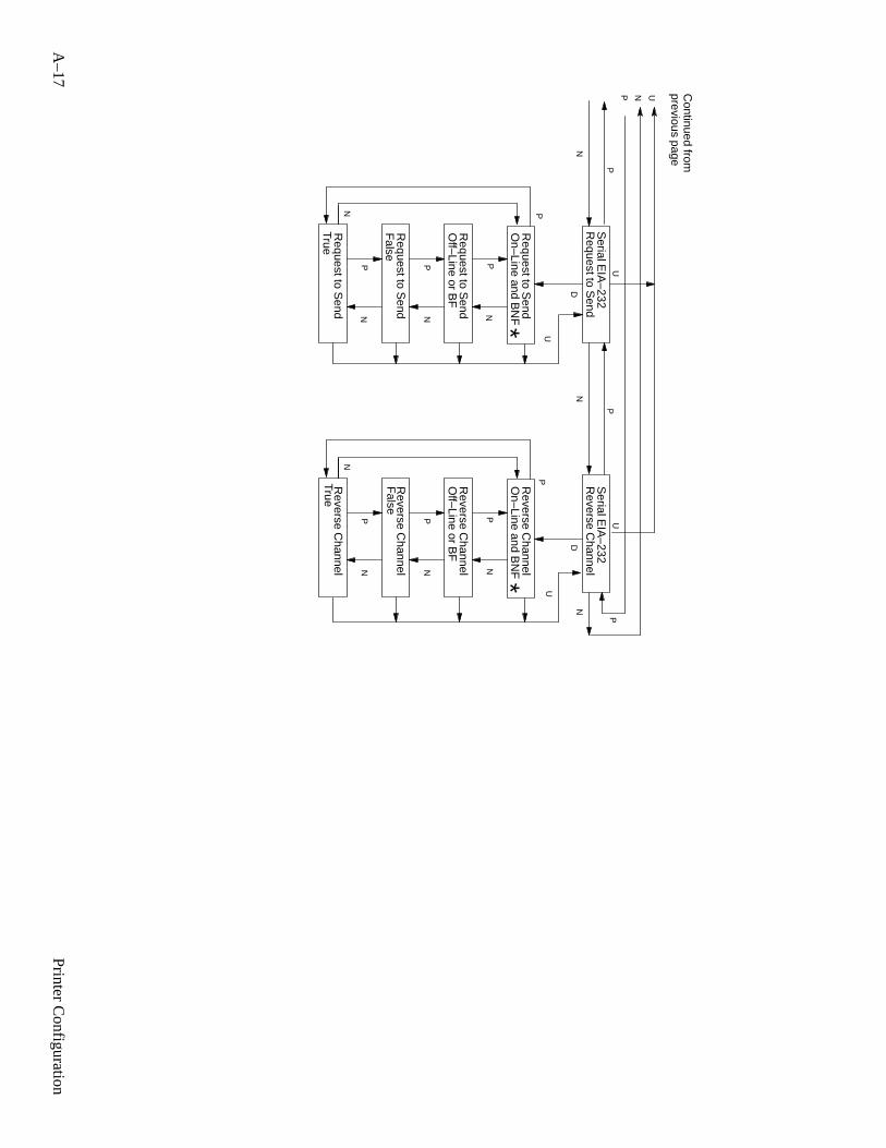
A–17
Printer C
onfiguration
Continued from
previous page
N
P
Reverse C
hannelD
PN
PN
PN
P
False
True
N
P
Request to S
endD
PN
PN
PN
P
False
True
UU
P UN
UU
NN
N
P
**
Request to S
end
Request to S
end
Request to S
end
Request to S
end
Reverse C
hannel
Reverse C
hannel
Reverse C
hannel
Reverse C
hannel
On–Line and B
NF
On–Line and B
NF
Off–Line or B
FO
ff–Line or BF
Serial E
IA–232
Serial E
IA–232
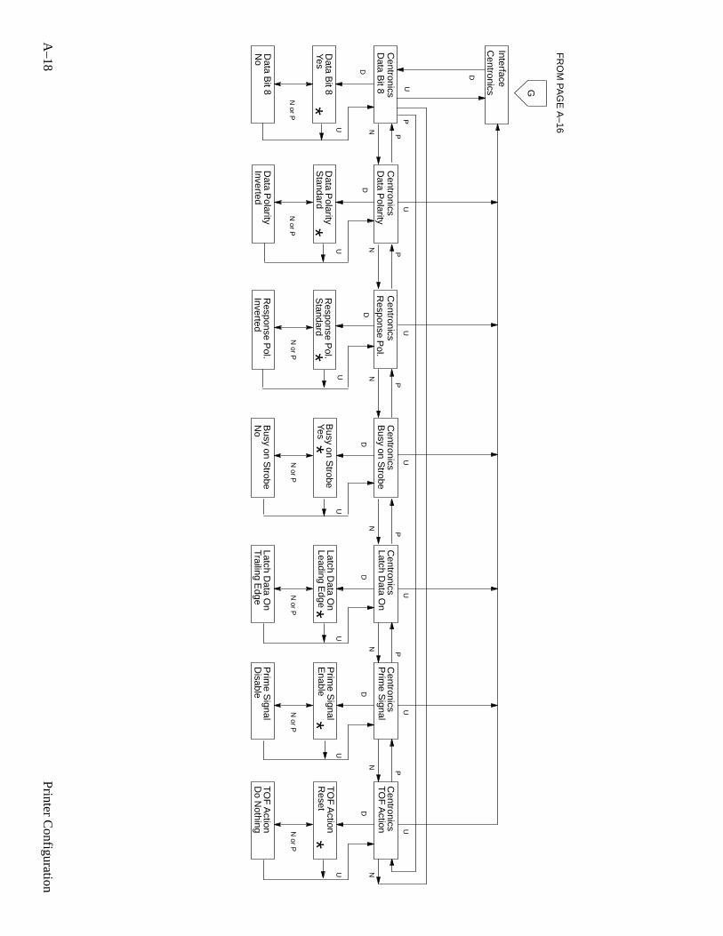
A–18
Printer C
onfiguration
Data B
it 8
Data B
it 8Yes
Data B
it 8N
o
Data P
olarity
Standard
Inverted
Data P
olarity
Data P
olarity
Standard
Inverted
Response P
ol.
Response P
ol.
Response P
ol.
Interface
NN
N
D
UP
PP
P
DD
D
UU
U
N or P
N or P
N or P
N
P
Latch Data O
n
Trailing Edge
Leading Edge
D
U
N or P
N
Latch Data O
n
Latch Data O
n
UU
U
**
**
G
FR
OM
PA
GE
A–16
Centronics
Busy on S
trobe
Yes
No
D
U
N or P
Busy on S
trobe
Busy on S
trobe
U
*
Centronics
Centronics
Centronics
Centronics
Centronics
Prim
e Signal
Disable
Enable D
U
N or P
Prim
e Signal
Prim
e Signal
U*
Centronics
TO
F A
ction
Do N
othing
Reset D
U
N or P
TO
F A
ction
TO
F A
ction U*
Centronics
N
P
N
P
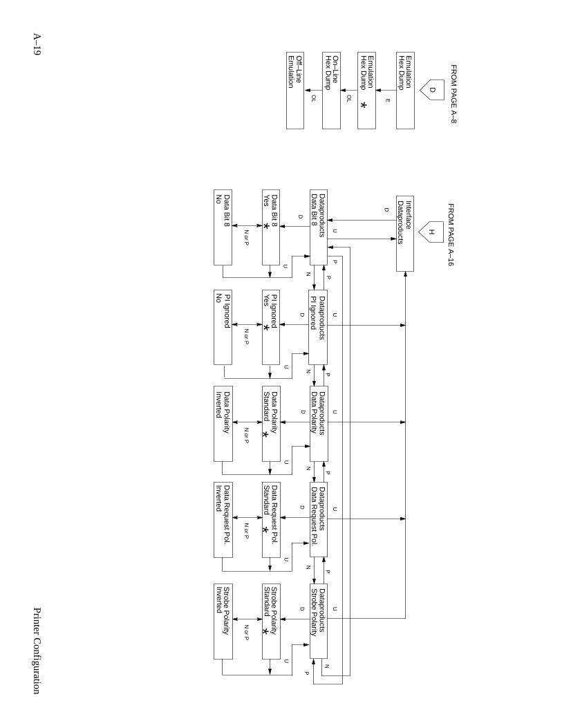
A–19
Printer C
onfiguration
D
Data B
it 8
Data B
it 8Yes
Data B
it 8N
o
Yes
No
Data P
olarity
Standard
Inverted
H
PI Ignored
PI Ignored
PI Ignored
Data P
olarity
Data P
olarity
Standard
Inverted
Data R
equest Pol.
UU
UU
NN
N
PP
PP
DD
DD
UU
UU
N or P
N or P
N or P
N or P
**
**
N
P
Standard
Inverted
Strobe P
olarity
Strobe P
olarity
Strobe P
olarity
D
U
N or P
*
Interface
FR
OM
PA
GE
A–16
U
Dataproducts
Dataproducts
Dataproducts
Dataproducts
Dataproducts
Data R
equest Pol.
Data R
equest Pol.
N
P
Em
ulation
Em
ulationH
ex Dum
p
OL
On–Line
Hex D
ump
E
Hex D
ump
*
Off–Line
Em
ulation
OL
D
FR
OM
PA
GE
A–8
Dataproducts
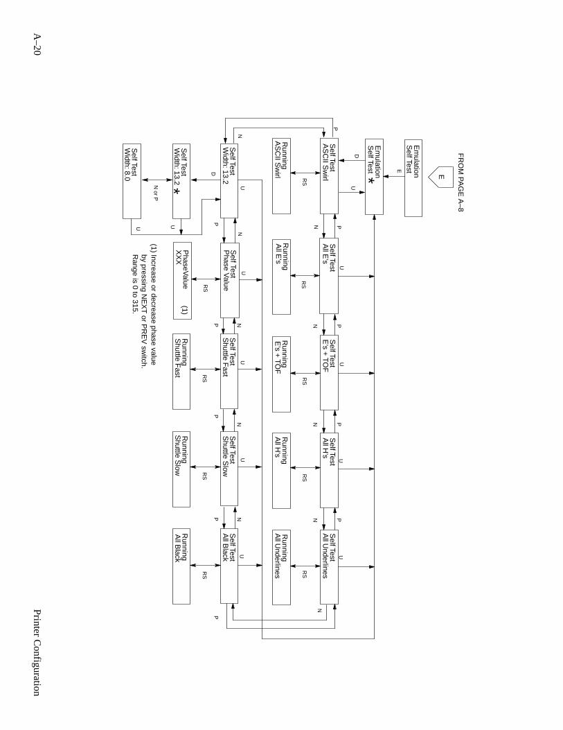
A–20
Printer C
onfiguration
PP
P
RS
RS
RS
RS
AS
CII S
wirl
All E
’sE
’s + T
OF
All H
’s
AS
CII S
wirl
All E
’sE
’s + T
OF
All H
’s
N
RS
All U
nderlines
All B
lack
RS
Running
Running
Running
Running
Running
Running
Running
All U
nderlines
Shuttle F
ast
Shuttle F
ast
E
U UU
UU
N
U
P
P
RS
Shuttle S
low
Running
Shuttle S
lowA
ll Black
N
P
U
RS
NN
NNP
Width: 13.2
NP
U
Self Test
Self Test
Self Test
Self Test
Self Test
Self Test
Self Test
Self Test
Self Test
N
*N or P
D
UU
Em
ulation
by pressing NE
XT
or PR
EV
switch.
Phase V
alue
(1)P
haseValue
Self Test
UN
P
RS
E
FR
OM
PA
GE
A–8
Self Test *
P
DU
Em
ulationS
elf Test
XX
XW
idth: 13.2S
elf Test
Width: 8.0
Self Test
Range is 0 to 315.
(1) Increase or decrease phase value
B–1Printer Specifications
B Printer Specifications
Contents
Cleaning Interval B–2. . . . . . . . . . . . . . . . . . . . . . . . . . . . . . . . . . . . . . . . . . . . . . . .
Ribbon Specifications B–2. . . . . . . . . . . . . . . . . . . . . . . . . . . . . . . . . . . . . . . . . . . .
Paper Specifications B–2. . . . . . . . . . . . . . . . . . . . . . . . . . . . . . . . . . . . . . . . . . . . .
Paper B–2. . . . . . . . . . . . . . . . . . . . . . . . . . . . . . . . . . . . . . . . . . . . . . . . . . . . . .
Labels B–3. . . . . . . . . . . . . . . . . . . . . . . . . . . . . . . . . . . . . . . . . . . . . . . . . . . . .
Printer Dimensions B–3. . . . . . . . . . . . . . . . . . . . . . . . . . . . . . . . . . . . . . . . . . . . . .
Interfaces B–3. . . . . . . . . . . . . . . . . . . . . . . . . . . . . . . . . . . . . . . . . . . . . . . . . . . . . .
Environmental Characteristics B–4. . . . . . . . . . . . . . . . . . . . . . . . . . . . . . . . . . . . . .
Termperature B–4. . . . . . . . . . . . . . . . . . . . . . . . . . . . . . . . . . . . . . . . . . . . . . . .
Relative Humidity B–4. . . . . . . . . . . . . . . . . . . . . . . . . . . . . . . . . . . . . . . . . . . .
Accoustic Noise Level B–4. . . . . . . . . . . . . . . . . . . . . . . . . . . . . . . . . . . . . . . .
Electrical Characteristics B–4. . . . . . . . . . . . . . . . . . . . . . . . . . . . . . . . . . . . . . . . . .
Input Power B–4. . . . . . . . . . . . . . . . . . . . . . . . . . . . . . . . . . . . . . . . . . . . . . . . .
Power Rating B–4. . . . . . . . . . . . . . . . . . . . . . . . . . . . . . . . . . . . . . . . . . . . . . . .
Data Input Rate B–5. . . . . . . . . . . . . . . . . . . . . . . . . . . . . . . . . . . . . . . . . . . . . .
Printing Rates B–6. . . . . . . . . . . . . . . . . . . . . . . . . . . . . . . . . . . . . . . . . . . . . . . . . .
Duty Cycle B–8. . . . . . . . . . . . . . . . . . . . . . . . . . . . . . . . . . . . . . . . . . . . . . . . . . . . .
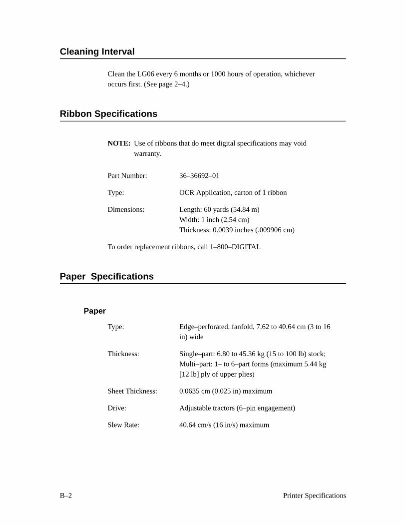
B–2 Printer Specifications
Cleaning Interval
Clean the LG06 every 6 months or 1000 hours of operation, whichever
occurs first. (See page 2–4.)
Ribbon Specifications
NOTE: Use of ribbons that do meet digital specifications may void
warranty.
Part Number: 36–36692–01
Type: OCR Application, carton of 1 ribbon
Dimensions: Length: 60 yards (54.84 m)Width: 1 inch (2.54 cm)
Thickness: 0.0039 inches (.009906 cm)
To order replacement ribbons, call 1–800–DIGITAL
Paper Specifications
Paper
Type: Edge–perforated, fanfold, 7.62 to 40.64 cm (3 to 16
in) wide
Thickness: Single–part: 6.80 to 45.36 kg (15 to 100 lb) stock;
Multi–part: 1– to 6–part forms (maximum 5.44 kg
[12 lb] ply of upper plies)
Sheet Thickness: 0.0635 cm (0.025 in) maximum
Drive: Adjustable tractors (6–pin engagement)
Slew Rate: 40.64 cm/s (16 in/s) maximum
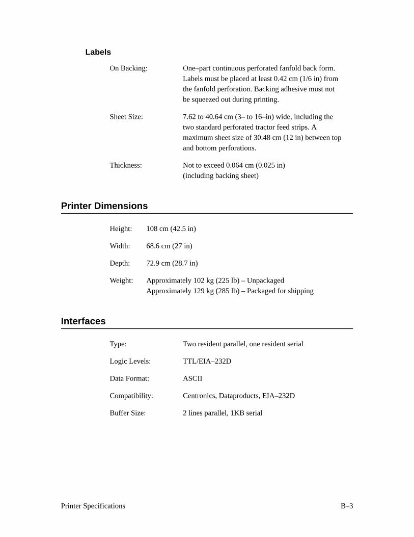
B–3Printer Specifications
Labels
On Backing: One–part continuous perforated fanfold back form.
Labels must be placed at least 0.42 cm (1/6 in) from
the fanfold perforation. Backing adhesive must notbe squeezed out during printing.
Sheet Size: 7.62 to 40.64 cm (3– to 16–in) wide, including the
two standard perforated tractor feed strips. A
maximum sheet size of 30.48 cm (12 in) between top
and bottom perforations.
Thickness: Not to exceed 0.064 cm (0.025 in)
(including backing sheet)
Printer Dimensions
Height: 108 cm (42.5 in)
Width: 68.6 cm (27 in)
Depth: 72.9 cm (28.7 in)
Weight: Approximately 102 kg (225 lb) – Unpackaged
Approximately 129 kg (285 lb) – Packaged for shipping
Interfaces
Type: Two resident parallel, one resident serial
Logic Levels: TTL/EIA–232D
Data Format: ASCII
Compatibility: Centronics, Dataproducts, EIA–232D
Buffer Size: 2 lines parallel, 1KB serial
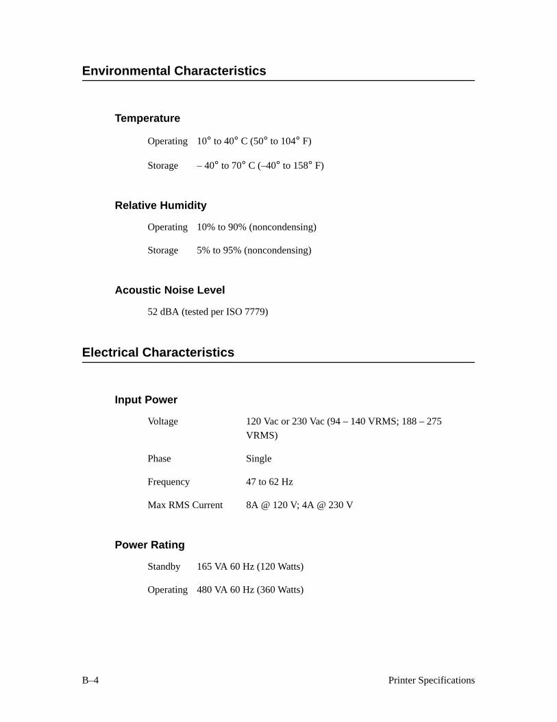
B–4 Printer Specifications
Environmental Characteristics
Temperature
Operating 10° to 40° C (50° to 104° F)
Storage – 40° to 70° C (–40° to 158° F)
Relative Humidity
Operating 10% to 90% (noncondensing)
Storage 5% to 95% (noncondensing)
Acoustic Noise Level
52 dBA (tested per ISO 7779)
Electrical Characteristics
Input Power
Voltage 120 Vac or 230 Vac (94 – 140 VRMS; 188 – 275
VRMS)
Phase Single
Frequency 47 to 62 Hz
Max RMS Current 8A @ 120 V; 4A @ 230 V
Power Rating
Standby 165 VA 60 Hz (120 Watts)
Operating 480 VA 60 Hz (360 Watts)

B–5Printer Specifications
Data Input Rate (maximum)
Dataproducts Up to 30 000 characters per second
Centronics Up to 30 000 characters per second
RS–232 Up to 19 200 baud
Radio Frequency Interference (RFI)
Radio Frequency Interference tested/certified to RFI standards FCC 15.J
Class A; VDE 0871 Class A; CISPR–22.
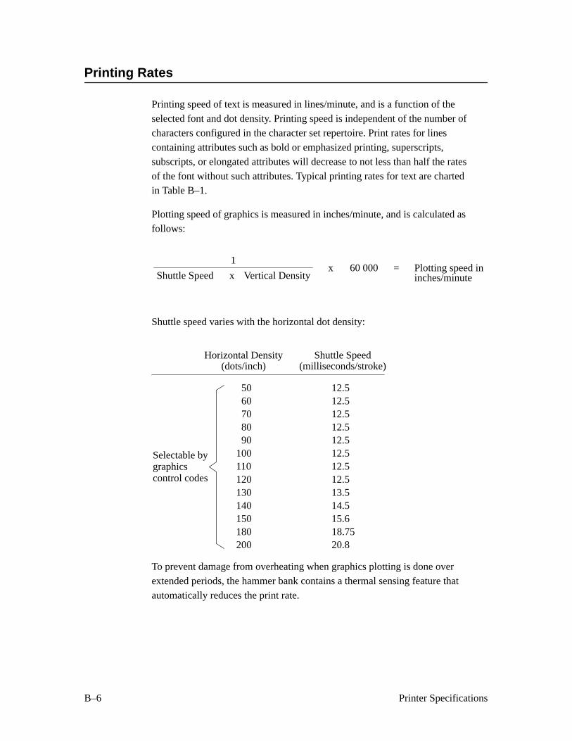
B–6 Printer Specifications
Printing Rates
Printing speed of text is measured in lines/minute, and is a function of the
selected font and dot density. Printing speed is independent of the number of
characters configured in the character set repertoire. Print rates for lines
containing attributes such as bold or emphasized printing, superscripts,
subscripts, or elongated attributes will decrease to not less than half the rates
of the font without such attributes. Typical printing rates for text are charted
in Table B–1.
Plotting speed of graphics is measured in inches/minute, and is calculated asfollows:
Shuttle Speed x Vertical Density60 000 Plotting speed in=
1x
inches/minute
Shuttle speed varies with the horizontal dot density:
Shuttle SpeedHorizontal Density(milliseconds/stroke)
12.512.512.512.512.512.512.512.513.514.515.618.7520.8
5060708090
100110120130140150180200
(dots/inch)
Selectable bygraphicscontrol codes
To prevent damage from overheating when graphics plotting is done over
extended periods, the hammer bank contains a thermal sensing feature that
automatically reduces the print rate.
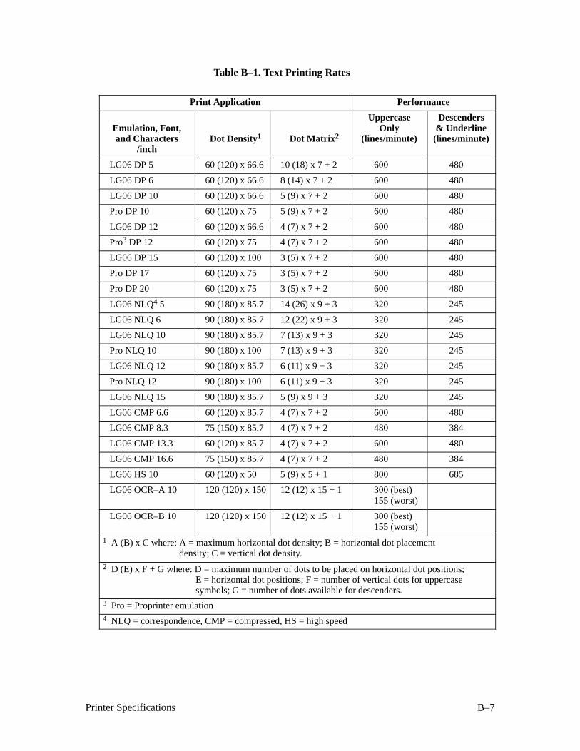
B–7Printer Specifications
Table B–1. Text Printing Rates
Print Application Performance
Emulation, Font,and Characters
/inchDot Density1 Dot Matrix 2
UppercaseOnly
(lines/minute)
Descenders& Underline(lines/minute)
LG06 DP 5 60 (120) x 66.6 10 (18) x 7 + 2 600 480
LG06 DP 6 60 (120) x 66.6 8 (14) x 7 + 2 600 480
LG06 DP 10 60 (120) x 66.6 5 (9) x 7 + 2 600 480
Pro DP 10 60 (120) x 75 5 (9) x 7 + 2 600 480
LG06 DP 12 60 (120) x 66.6 4 (7) x 7 + 2 600 480
Pro3 DP 12 60 (120) x 75 4 (7) x 7 + 2 600 480
LG06 DP 15 60 (120) x 100 3 (5) x 7 + 2 600 480
Pro DP 17 60 (120) x 75 3 (5) x 7 + 2 600 480
Pro DP 20 60 (120) x 75 3 (5) x 7 + 2 600 480
LG06 NLQ4 5 90 (180) x 85.7 14 (26) x 9 + 3 320 245
LG06 NLQ 6 90 (180) x 85.7 12 (22) x 9 + 3 320 245
LG06 NLQ 10 90 (180) x 85.7 7 (13) x 9 + 3 320 245
Pro NLQ 10 90 (180) x 100 7 (13) x 9 + 3 320 245
LG06 NLQ 12 90 (180) x 85.7 6 (11) x 9 + 3 320 245
Pro NLQ 12 90 (180) x 100 6 (11) x 9 + 3 320 245
LG06 NLQ 15 90 (180) x 85.7 5 (9) x 9 + 3 320 245
LG06 CMP 6.6 60 (120) x 85.7 4 (7) x 7 + 2 600 480
LG06 CMP 8.3 75 (150) x 85.7 4 (7) x 7 + 2 480 384
LG06 CMP 13.3 60 (120) x 85.7 4 (7) x 7 + 2 600 480
LG06 CMP 16.6 75 (150) x 85.7 4 (7) x 7 + 2 480 384
LG06 HS 10 60 (120) x 50 5 (9) x 5 + 1 800 685
LG06 OCR–A 10 120 (120) x 150 12 (12) x 15 + 1 300 (best)155 (worst)
LG06 OCR–B 10 120 (120) x 150 12 (12) x 15 + 1 300 (best)155 (worst)
1 A (B) x C where: A = maximum horizontal dot density; B = horizontal dot placement density; C = vertical dot density.
2 D (E) x F + G where: D = maximum number of dots to be placed on horizontal dot positions;E = horizontal dot positions; F = number of vertical dots for uppercase symbols; G = number of dots available for descenders.
3 Pro = Proprinter emulation4 NLQ = correspondence, CMP = compressed, HS = high speed

B–8 Printer Specifications
Duty Cycle
The LG06 text and graphics printer is capable of printing 75 000 pages per
month under the following conditions:
1. Uppercase only
2. 6 lines/inch
3. 10 characters/inch
4. 63% character density or 83 characters/line
5. 63% line density or 42 lines/11–inch page
6. Single part (18 lb) paper
7. Printer is maintained in accordance with the maintenance manual
(document number EK–ELG06–MG)
8. Printer is installed in accordance with Chapter 2, “Installation” of the
User’s Manual (document number EK–ELG06–UG).
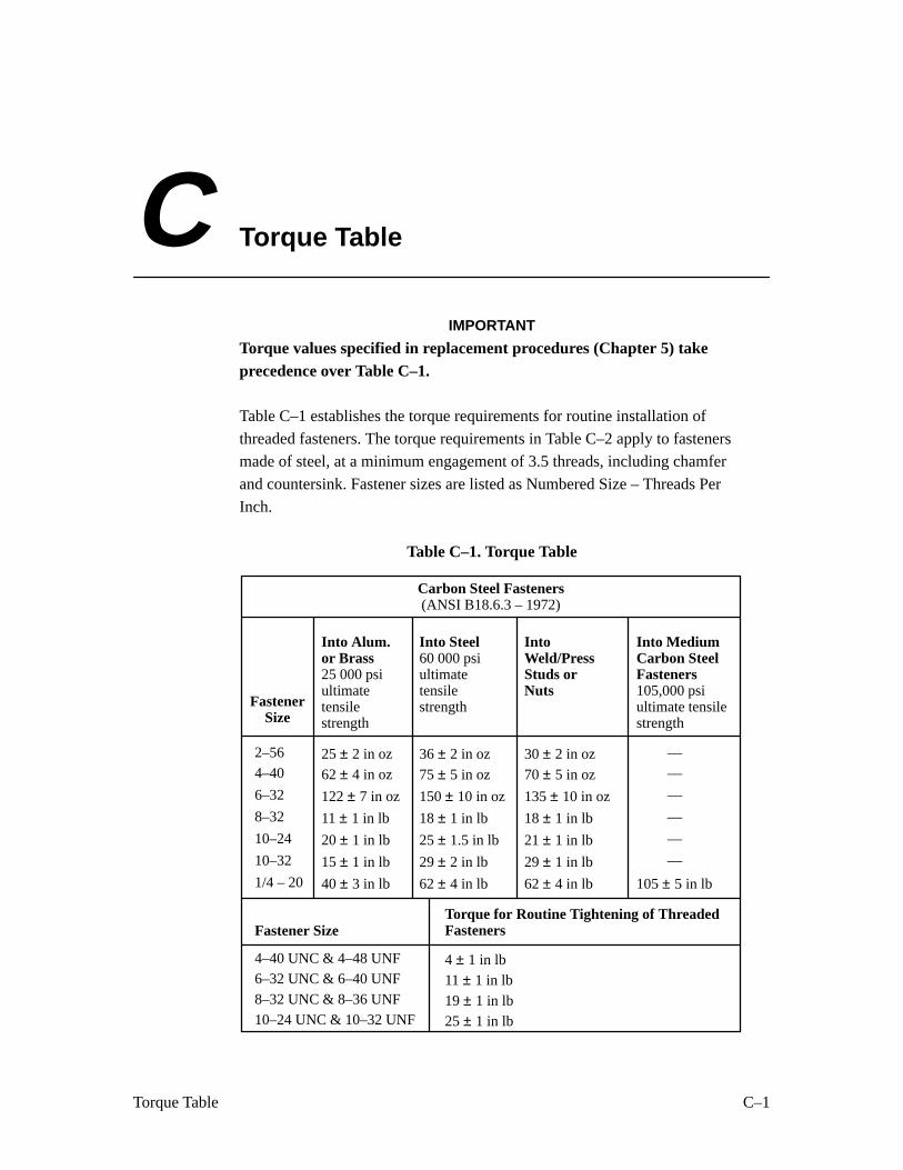
C–1Torque Table
C Torque Table
IMPORTANT
Torque values specified in replacement procedures (Chapter 5) takeprecedence over Table C–1.
Table C–1 establishes the torque requirements for routine installation of
threaded fasteners. The torque requirements in Table C–2 apply to fastenersmade of steel, at a minimum engagement of 3.5 threads, including chamfer
and countersink. Fastener sizes are listed as Numbered Size – Threads Per
Inch.
Table C–1. Torque Table
FastenerSize
Into Alum.or Brass25 000 psiultimatetensilestrength
IntoWeld/PressStuds orNuts
Into MediumCarbon SteelFasteners105,000 psiultimate tensilestrength
Into Steel60 000 psiultimatetensilestrength
Carbon Steel Fasteners(ANSI B18.6.3 – 1972)
2–56
4–40
6–32
8–32
10–24
10–32
1/4 – 20
25 ± 2 in oz
62 ± 4 in oz
122 ± 7 in oz
11 ± 1 in lb
20 ± 1 in lb
15 ± 1 in lb
40 ± 3 in lb
36 ± 2 in oz
75 ± 5 in oz
150 ± 10 in oz
18 ± 1 in lb
25 ± 1.5 in lb
29 ± 2 in lb
62 ± 4 in lb
30 ± 2 in oz
70 ± 5 in oz
135 ± 10 in oz
18 ± 1 in lb
21 ± 1 in lb
29 ± 1 in lb
62 ± 4 in lb
––
––
105 ± 5 in lb
––
––
––
––
Fastener SizeTorque for Routine Tightening of ThreadedFasteners
4–40 UNC & 4–48 UNF 4 ± 1 in lb6–32 UNC & 6–40 UNF 11 ± 1 in lb8–32 UNC & 8–36 UNF 19 ± 1 in lb10–24 UNC & 10–32 UNF 25 ± 1 in lb

C–2 Torque Table
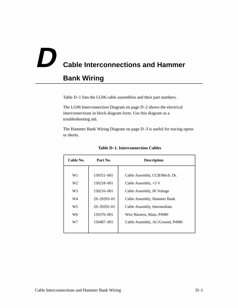
D–1Cable Interconnections and Hammer Bank Wiring
D Cable Interconnections and Hammer
Bank Wiring
Table D–1 lists the LG06 cable assemblies and their part numbers.
The LG06 Interconnection Diagram on page D–2 shows the electrical
interconnections in block diagram form. Use this diagram as a
troubleshooting aid.
The Hammer Bank Wiring Diagram on page D–3 is useful for tracing opens
or shorts.
Table D–1. Interconnection Cables
Cable No.
W1
W2
W3
W4
W5
W6
W7
150551–001
150218–001
150216–001
29–29293–01
29–29292–01
150376–001
150487–001
Cable Assembly, CCB/Mech. Dr.
Part No. Description
Cable Assembly, +5 V
Cable Assembly, Hi Voltage
Cable Assembly, Hammer Bank
Cable Assembly, Intermediate
Wire Harness, Main, P4980
Cable Assembly, AC/Ground, P4980
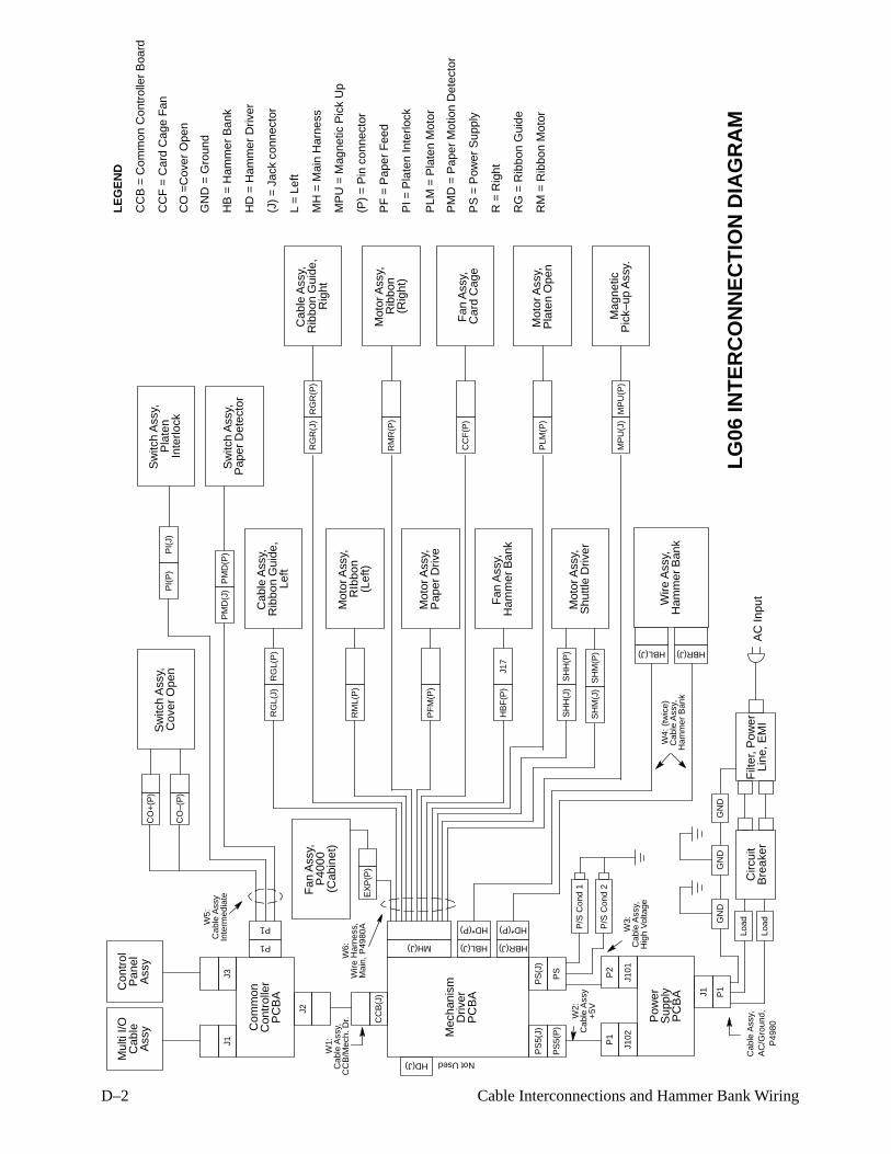
D–2 Cable Interconnections and Hammer Bank Wiring
Com
mon
J1
Con
trol
ler
LG06
INT
ER
CO
NN
EC
TIO
N D
IAG
RA
M
Mul
ti I/O
Cab
leA
ssy
P1
PC
BA
J3
Con
trol
Pan
elA
ssy
P1
J2
CC
B(J
)
W1:
Mec
hani
smD
river
PC
BA
HD(J) Not Used
MH(J) HBL(J)
HD*(P)
HBR(J)
HD*(P)
Sw
itch
Ass
y,C
over
Ope
n
Cab
le A
ssy,
Rib
bon
Gui
de,
Mot
or A
ssy,
RIb
bon
Mot
or A
ssy,
Pap
er D
rive
Fan
Ass
y,H
amm
er B
ank
Mot
or A
ssy,
Shu
ttle
Driv
er
Wire
Ass
y,H
amm
er B
ank
Sw
itch
Ass
y,P
late
n
Sw
itch
Ass
y,P
aper
Det
ecto
r
Cab
le A
ssy,
Rib
bon
Gui
de,
Mot
or A
ssy,
Rib
bon
Fan
Ass
y,C
ard
Cag
e
Mot
or A
ssy,
Pla
ten
Ope
n
Mag
netic
Pic
k–up
Ass
y.
Pow
er
J102
Sup
ply
PC
BA
J101
J1
PS
5(P
)P
S
PS
(J)
PS
5(J)
LEG
EN
D
Left
Inte
rlock
Rig
htF
an A
ssy,
P40
00
Circ
uit
Bre
aker
Filt
er, P
ower
Line
, EM
I
P1
AC
Inpu
tLo
ad
LoadG
ND
GN
DG
ND
Cab
le A
ssy,
AC
/Gro
und,
P49
80
P2
P1
P/S
Con
d 1
P/S
Con
d 2
W3:
Cab
le A
ssy,
Hig
h V
olta
ge
W2:
Cab
le A
ssy
+5V
Cab
le A
ssy,
CC
B/M
ech.
Dr.
W6:
Wire
Har
ness
,M
ain,
P49
80A
EX
P(P
)
HBL(J) HBR(J)
W4:
(tw
ice)
Cab
le A
ssy,
Ham
mer
Ban
k
CO
+(P
)
CO
–(P
)
PM
D(P
)P
MD
(J)
PI(
J)P
I(P
)
W5:
Cab
le A
ssy
Inte
rmed
iate
RG
L(P
)R
GL(
J)
RM
L(P
)
PF
M(P
)
J17
HB
F(P
)
SH
H(P
)S
HH
(J)
RG
R(P
)R
GR
(J)
RM
R(P
)
CC
F(P
)
PLM
(P)
MP
U(P
)M
PU
(J)
SH
M(P
)S
HM
(J)
(Rig
ht)
(Lef
t)
(J)
= J
ack
conn
ecto
r
(P)
= P
in c
onne
ctor
HD
= H
amm
er D
river
PS
= P
ower
Sup
ply
MH
= M
ain
Har
ness
HB
= H
amm
er B
ank
R =
Rig
ht
L =
Lef
t
RG
= R
ibbo
n G
uide
RM
= R
ibbo
n M
otor
PF
= P
aper
Fee
d
CC
F =
Car
d C
age
Fan
PLM
= P
late
n M
otor
MP
U =
Mag
netic
Pic
k U
p
GN
D =
Gro
und
PM
D =
Pap
er M
otio
n D
etec
tor
PI =
Pla
ten
Inte
rlock
CO
=C
over
Ope
n
CC
B =
Com
mon
Con
trol
ler
Boa
rd
(Cab
inet
)
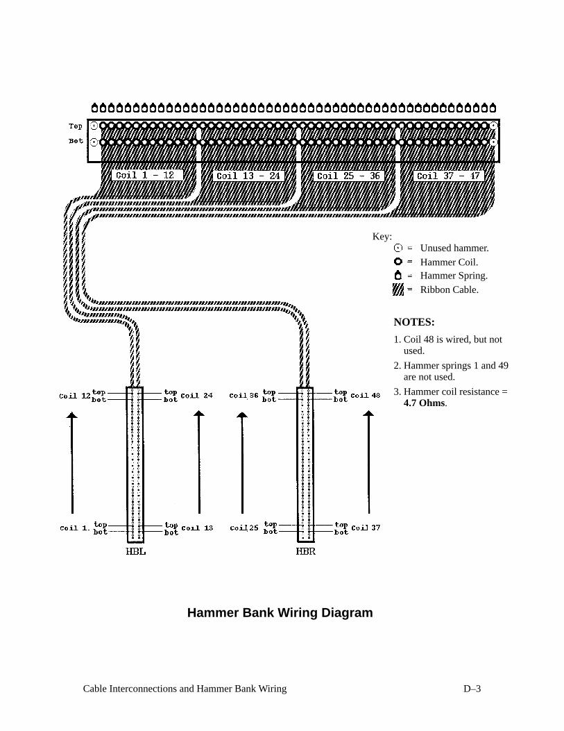
D–3Cable Interconnections and Hammer Bank Wiring
Hammer Bank Wiring Diagram
NOTES:
1. Coil 48 is wired, but notused.
2. Hammer springs 1 and 49are not used.
3. Hammer coil resistance =4.7 Ohms.
Unused hammer.
Hammer Coil.Hammer Spring.
Ribbon Cable.
Key:

D–4 Cable Interconnections and Hammer Bank Wiring
E–1Principles of Operation
E Principles of Operation
Contents
Functional Elements of the Printer E–2. . . . . . . . . . . . . . . . . . . . . . . . . . . . . . . . . .
Common Controller PCBA E–3. . . . . . . . . . . . . . . . . . . . . . . . . . . . . . . . . . . . . . . .
Mechanism Driver PCBA E–11. . . . . . . . . . . . . . . . . . . . . . . . . . . . . . . . . . . . . . . . .
Power Supply PCBA E–14. . . . . . . . . . . . . . . . . . . . . . . . . . . . . . . . . . . . . . . . . . . . .
Printing Mechanism E–15. . . . . . . . . . . . . . . . . . . . . . . . . . . . . . . . . . . . . . . . . . . . . .
Paper Transport System E–19. . . . . . . . . . . . . . . . . . . . . . . . . . . . . . . . . . . . . . . . . . .
Ribbon Transport System E–20. . . . . . . . . . . . . . . . . . . . . . . . . . . . . . . . . . . . . . . . .
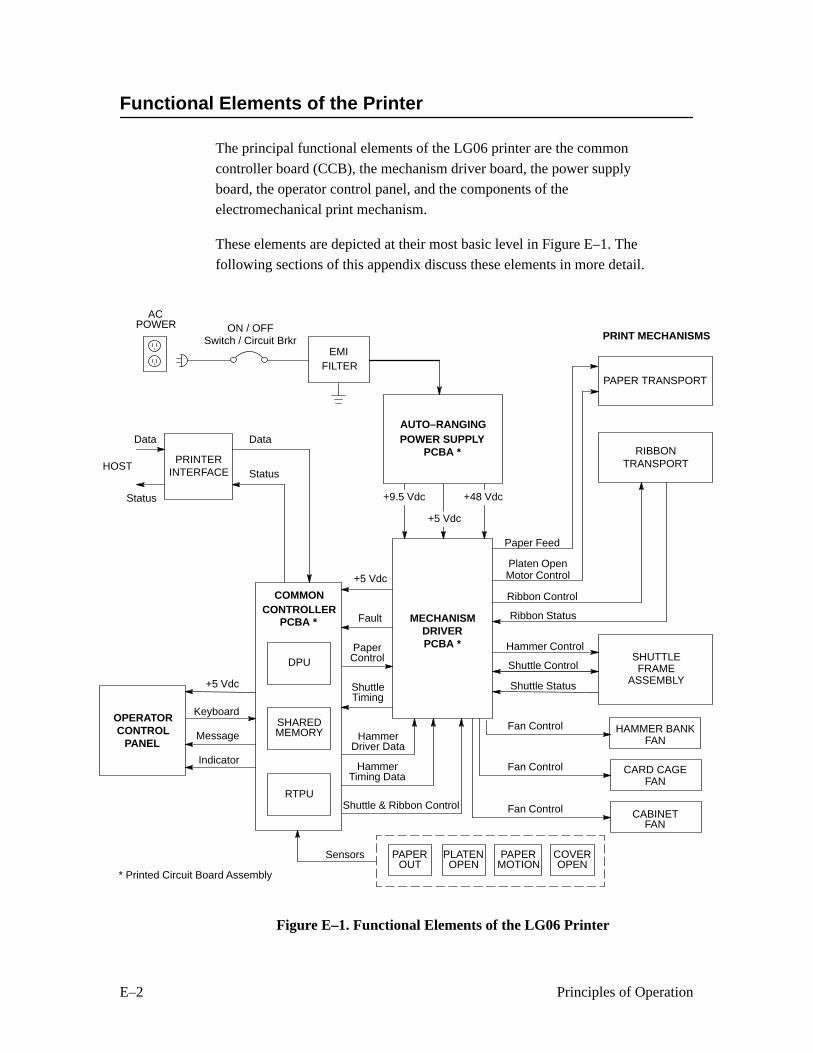
E–2 Principles of Operation
Functional Elements of the Printer
The principal functional elements of the LG06 printer are the common
controller board (CCB), the mechanism driver board, the power supplyboard, the operator control panel, and the components of the
electromechanical print mechanism.
These elements are depicted at their most basic level in Figure E–1. The
following sections of this appendix discuss these elements in more detail.
POWER SUPPLYPCBA *
CONTROLLERPCBA *
OPERATORCONTROL
PANEL
MECHANISMDRIVERPCBA *
PRINT MECHANISMS
SHUTTLEFRAME
ASSEMBLY
RIBBONTRANSPORT
Paper Feed
Platen OpenMotor Control
Shuttle Control
Ribbon Control
Fan Control
Shuttle Status
Hammer Control
Ribbon Status
+5 Vdc
Data
Status
+5 Vdc
ACPOWER
PRINTERINTERFACE
COMMON
FILTEREMI
Fault
HammerDriver Data
HammerTiming Data
Shuttle & Ribbon Control
PaperControlDPU
RTPU
SHAREDMEMORY
Keyboard
Indicator
Message
ON / OFFSwitch / Circuit Brkr
AUTO–RANGING
PAPER TRANSPORT
CABINETFAN
CARD CAGEFAN
HAMMER BANKFAN
Fan Control
Fan Control
Status
Data
HOST
ShuttleTiming
PAPERMOTION
PAPEROUT
COVEROPEN
PLATENOPEN
Sensors
+48 Vdc+9.5 Vdc
+5 Vdc
* Printed Circuit Board Assembly
Figure E–1. Functional Elements of the LG06 Printer
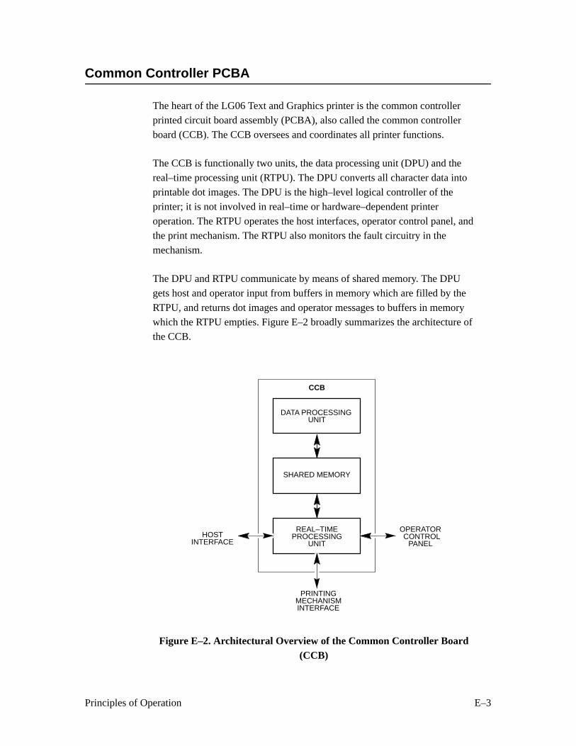
E–3Principles of Operation
Common Controller PCBA
The heart of the LG06 Text and Graphics printer is the common controller
printed circuit board assembly (PCBA), also called the common controller
board (CCB). The CCB oversees and coordinates all printer functions.
The CCB is functionally two units, the data processing unit (DPU) and the
real–time processing unit (RTPU). The DPU converts all character data into
printable dot images. The DPU is the high–level logical controller of the
printer; it is not involved in real–time or hardware–dependent printer
operation. The RTPU operates the host interfaces, operator control panel, and
the print mechanism. The RTPU also monitors the fault circuitry in the
mechanism.
The DPU and RTPU communicate by means of shared memory. The DPU
gets host and operator input from buffers in memory which are filled by the
RTPU, and returns dot images and operator messages to buffers in memory
which the RTPU empties. Figure E–2 broadly summarizes the architecture of
the CCB.
HOSTINTERFACE
OPERATOR CONTROL
PANEL
PRINTINGMECHANISMINTERFACE
DATA PROCESSING
SHARED MEMORY
REAL–TIME
CCB
UNIT
PROCESSINGUNIT
Figure E–2. Architectural Overview of the Common Controller Board(CCB)

E–4 Principles of Operation
Communicating with the Host Computer
The CCB processes three kinds of computer input: Centronics parallel,
DataProducts parallel, and RS–232 serial data. The RTPU operates all three
interfaces. The parallel interfaces are similar, and the RTPU contains
direct–memory–access (DMA) hardware which loads parallel data directly
into shared memory. The serial interface requires byte–by–byte intervention
by the processor, since ACK/NACK and XON/XOFF protocols require that
every byte be examined as it is received. The universal asynchronous
receiver/transmitter (UART) is internal to the RTPU, which processes any
protocol requirements then puts the data in shared memory, where the DPU
can read it. To the DPU, all input data looks the same, regardless of the
interface used to receive it.
Communicating with the Operator
All communication to and from the operator is done at the operator control
panel. The control panel processes three types of operation: keystroke input,
message display output, and indicator output. The RTPU handles the control
panel interface requirements of shifting, clocking, etc., but the DPU
processes all control panel data.
Printing
The RTPU coordinates printing of the dot images sent from the DPU.Printing is a complex process requiring many control functions, but is
logically divided into two groups:
• Hammer driver interface functions
• Mechanical interface functions
Hammer Driver Interface
In order to print a dot image, two things must happen. First, the dots must get
to the hammers one dot row at a time and in the correct sequence. Second,
the hammers must be fired at the appropriate time in the stroke of the shuttle.
The RTPU microprocessor controls both of these functions, but each is
actually performed by an application–specific integrated circuit (ASIC)
containing hardware dedicated to the function. These ASICs are the Dot
Plucker Memory Controller (DPMC) and the Fire Timer IC (FTIC). The
hammer driver interface functions of the RTPU are summarized in
Figure E–3.

E–5Principles of Operation
DATA PROCESSING
RTPU
REAL–TIME PROCESSING UNIT
UNIT
64180PROCESSOR
DMA CONTROLLER
DOT PLUCKER
FIRE TIMEREPROM
SHARED MEMORY HammerDriverData
HammerTimingData
ASIC
ASIC
Figure E–3. Hammer Driver Interface Functions of the RTPU
Getting Dots to the Hammers Getting dots to the hammers consists of
going into the shared memory and pulling bits out in a given order and
shifting them to the hammer driver at the correct time. This process is calleddot plucking. The order in which dots are plucked from memory depends on
the dot density, the number of dots per hammer, the number of hammers on
the hammer bank, the number of phases, and other factors. These factors are
all considered by the RTPU processor as it programs the dot plucker for each
dot row.
Synchronizing Dot Plucking and Hammer Firing Transfer of dots to
the hammer driver must be synchronized with hammer firing. Dots are
transferred to the hammer driver in bursts, serial streams of dots that tellwhich hammers will print when their phase is next fired. The bursts are timed
precisely; they must occur neither too early nor too late. Synchronization is
performed by having the FTIC request bursts from the dot plucker. The FTIC
reads the magnetic pick–up unit (MPU) to determine when to request a burst.
The time at which the burst request is made is contained in the fire timing
tables.
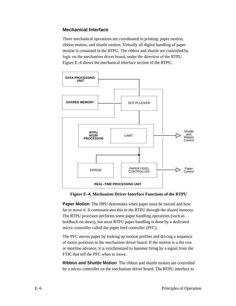
E–6 Principles of Operation
Mechanical Interface
Three mechanical operations are coordinated in printing: paper motion,
ribbon motion, and shuttle motion. Virtually all digital handling of paper
motion is contained in the RTPU. The ribbon and shuttle are controlled by
logic on the mechanism driver board, under the direction of the RTPU.
Figure E–4 shows the mechanical interface section of the RTPU.
DATA PROCESSING
RTPU
REAL–TIME PROCESSING UNIT
UNIT
64180PROCESSOR
UART
DOT PLUCKER
PAPER FEEDEPROM
SHARED MEMORY
Shuttleand
Ribbon
PaperControlCONTROLLER
Control
Figure E–4. Mechanism Driver Interface Functions of the RTPU
Paper Motion The DPU determines when paper must be moved and how
far to move it. It communicates this to the RTPU through the shared memory.
The RTPU processor performs some paper handling operations (such as
holdback on slews), but most RTPU paper handling is done by a dedicated
micro–controller called the paper feed controller (PFC).
The PFC moves paper by looking up motion profiles and driving a sequence
of motor positions to the mechanism driver board. If the motion is a dot row
or interline advance, it is synchronized to hammer firing by a signal from theFTIC that tell the PFC when to move.
Ribbon and Shuttle Motion The ribbon and shuttle motors are controlled
by a micro–controller on the mechanism driver board. The RTPU interface to

E–7Principles of Operation
the ribbon/shuttle processor (RSP) is a 2400 baud asynchronous serial line. A
message protocol is used to communicate ribbon and shuttle information.
Fault Monitoring
The RTPU also monitors the hammer driver, mechanism driver, and the
electro–mechanical sensors for fault conditions. Fault conditions are reported
to the DPU.
Hammer Bank and Hammer Driver Faults
The FTIC works with the hammer driver ASIC to monitor coil shorts, opens,
average upper driven phase current, and temperature conditions. The RTPU
reads the FTIC registers to determine out–of–range conditions, and these are
passed on to the DPU.
Paper Faults
Two kinds of paper faults can occur: paper out and paper jammed. Both of
these conditions are monitored through optical sensors. The paper feed
controller watches the paper out and paper motion sensors and reports errors
to the RTPU. The RTPU passes this information on to the DPU.
Ribbon and Shuttle Faults
The mechanism driver ribbon and shuttle controller monitors fault conditions
in the drive circuits and notifies the RTPU if it finds errors. The RTPU can
also use the FTIC to measure time between magnetic pick–up (MPU) pulses,
enabling it to monitor shuttle speed and thus detect some shuttle faults.
CCB Hardware Overview
A Motorola 68010 microprocessor performs the DPU functions, a 64180
microprocessor handles the RTPU functions, and an 8032 micro–controller
serves as the paper feed controller (PFC), which is part of the RTPU. Actual
implementation of this hardware blurs the distinctions between the DPU and
RTPU, since the 68010 has access to the parallel port and the real–time
functions of the dot plucker, which are RTPU resources, while the 64180 has
access to the nonvolatile memory (NVRAM), which is a resource of the
DPU. These possibilities exist because of efficiencies in the hardware design;software maintains the functional differences between the DPU and RTPU.
The CCB has four data buses. The 68010 has a local sixteen bit bus. The
64180 uses a local bus eight bits wide. A third bus is shared by the DPU and
E–8 Principles of Operation
RTPU; it is sixteen bits wide and is arbitrated on a cycle–by–cycle basis. The
8032 chip has its own eight bit local bus. The manner in which the CCB
implements this hardware is depicted in Figure E–5.
The 64180 IC that oversees the RTPU processor contains a Z80
microprocessor with extended memory management, two DMA controllers,
two asynchronous and one synchronous serial port, two counter timers, and
an interrupt controller.
Communicating with the Host Computer
The 64180 processor runs both the parallel and serial interfaces.
Parallel Input Parallel input data is nine bits wide, and is transferred in one
cycle from the parallel port to shared memory over the shared sixteen bit bus.
Using the internal DMA controller of the 64180 to transfer parallel data
requires some manipulation. The eight bit DMA controller in the 64180
performs either eight or sixteen bit DMA cycles, while the eight bit processor
in the 64180 performs only eight bit memory access cycles. Sixteen bit DMA
is achieved by hardware shifting of the DMA addresses one bit (effectively
multiplying the address by two and changing the DMA auto–increment from
byte to word) and by manipulating the control strobe. Software adjusts the
addresses provided to the DMA controller when it is programmed for sixteen
bit DMA. This manipulation saves both the added cost of a sixteen bit DMA
controller and the second cycle that an eight bit transfer would require.
Serial Input One of the 64180 UARTs handles serial communication with
the host. Additional modem control lines are provided in the 64180 hardwarecontrol register.
Communicating with the Operator
The synchronous serial port in the 64180 shifts data in and out of the operator
control panel. The control register in the 64180 contains three other control
panel bits: one samples the switches, one strobes the liquid–crystal display,
and one strobes a light–emitting diode (LED) holding register.
Printing
Hammer Driver Interface The 64180 programs the dot plucker ASIC
every dot row and programs the FTIC every stroke, after which the FTIC
uses a DMA request line to control the movement of tables from EPROM to
FTIC. The second DMA controller in the 64180 performs this transfer.
Mechanism Driver Interface The paper feed controller (PFC) directs all
paper motion. During printing, it usually moves paper in response to a trigger

E–9Principles of Operation
from the FTIC, which synchronizes paper motion with shuttle motion. The
64180 programs the PFC 8032 at the beginning of each dot row, telling the
PFC how far to move when the trigger is received. The PFC sets up for the
move, waits, then moves when the trigger occurs. The other method of
starting paper motion is with a command passed through the inter–processor
port (an eight bit parallel port between the 8032 and the 64180). This results
in immediate movement. Other paper commands and status signals are also
passed through this port.
Ribbon and Shuttle Motion The 64180 interfaces through its second
UART to the ribbon / shuttle processor (RSP) on the mechanism driver
board. The 64180 begins all transactions on the serial interface; the RSP sets
a bit in the 64180 hardware status register when it needs service.
Fault Monitoring
The RTPU 64180, the PFC 8032, and the RSP monitor different functions for
faults. The 64180 looks for hammer driver faults, shuttle stalls, and an open
platen. The PFC 8032 monitors paper out and the paper motion detector. The
RSP watches for faults in the motor drive circuits. The PFC and RSP report
errors to the 64180, which collates fault status and passes it on to the DPU68010 processor.
Hammer Bank and Hammer Driver Faults The 64180 and FTIC check
the hammer driver and hammer bank for faults on every shuttle stroke. Faults
are detected by circuits on the mechanism driver board and relayed to the
CCB. Fault circuitry can detect shorted coils and rising temperatures in the
coils. One coil is checked on every shuttle stroke; 48 shuttle strokes are
required to check all coils. When the RTPU is notified of a fault, it sends a
message to the 68010. If a coil shorts, the 64180 stops printing before firing
another dot row.
Paper Faults The PFC 8032 monitors paper faults and reports them to the
64180 through the eight bit parallel port they share. The PFC works with a
friction wheel paper motion detector and a reflective (optical) paper out
sensor. The sensors interface directly to the CCB; there are analog circuits on
the CCB to condition the sensor inputs.
Ribbon and Shuttle Faults The RSP monitors ribbon and shuttle faults
and reports them to the 64180 over the serial interface.
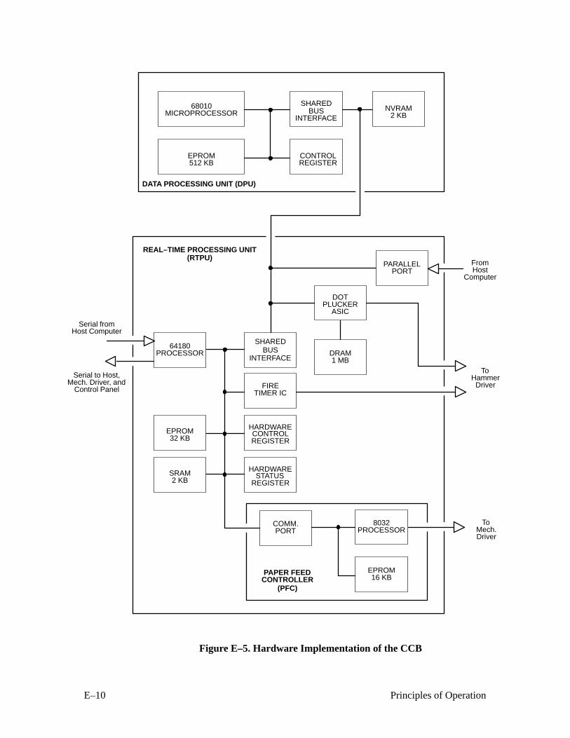
E–10 Principles of Operation
DATA PROCESSING UNIT (DPU)
PAPER FEED
68010
CONTROLLER
EPROM
FromHost
Computer
ToHammer
REAL–TIME PROCESSING UNIT
MICROPROCESSOR
512 KB
Driver
ToMech.Driver
Serial to Host,Mech. Driver, and
Control Panel
PARALLELPORT
DOTPLUCKER
DRAM1 MB
BUSINTERFACE
FIRETIMER IC
HARDWARECONTROL
HARDWARESTATUS
REGISTER
REGISTER
COMM.PORT
8032PROCESSOR
EPROM16 KB
EPROM32 KB
SRAM2 KB
64180PROCESSOR
BUSINTERFACE
CONTROLREGISTER
NVRAM2 KB
(RTPU)
(PFC)
SHARED
SHARED
ASIC
Serial fromHost Computer
Figure E–5. Hardware Implementation of the CCB

E–11Principles of Operation
Mechanism Driver PCBA
The mechanism driver board, acting on commands from the CCB, controls
real–time operation of the electromechanical printer systems. Functionally,
the board consists of nine subsystems:
• An 8032 micro–controller that controls ribbon drive and
communication with the CCB.
• The interface to the power supply board.
• Pulse–width modulator (PWM) current mode / voltage mode
full–bridge power amplifiers connected directly to the shuttle,
ribbon, paper feed, and platen open motors. Current mode is used for
the paper feed motor, voltage mode is used for the ribbon and shuttle
motors.
• The paper feed controller (PFC) accepts control codes from the CCB
for each motor phase to vector–control the paper feed motor.
• The shuttle drive controller receives speed commands from the CCB
through the 8032 micro–controller and commands the speed of the
three–phase dc shuttle motor.
• The ribbon drive controller, based around the 8032 micro–controller,
receives speed commands from the CCB and drives two dc stepper
motors, regulating the speed and tension of the ribbon and
monitoring the end of ribbon sensors.
• The platen drive controller for reverse paper feed.
• Fault detection circuitry samples and senses heat sink temperature,
ribbon speed, shuttle speed, hammer driver circuitry, hammer bank
coil temperatures, power supply voltages, and fault communication
with the CCB.
• Circuitry that registers magnetic pick–up unit (MPU) output,processes it for the logic interface, and sends it to the CCB for
timing hammer fire.
The Ribbon Drive System
The ribbon drive system is controlled by the 8032 micro–controller. The
CCB sends commands to the 8032 to start and stop the ribbon, set the ribbon
speed, and apply slack or tension to the ribbon. The real–time control
functions are done by the 8032, acting in accordance with firmware control
algorithms and look–up tables. The 8032 communicates with an ASIC to
E–12 Principles of Operation
provide direct digital PWM drive signals for the ribbon motor PWM
amplifier. The 8032 drives the ribbon motors through PWM generators in the
mechanism driver integrated circuit (MDIC). Nearly all mechanical control
functions are carried out through the MDIC ASIC. Digital I/O is done
through latches connected to the 8032 I/O ports and MDIC. Ribbon faults are
passed to the CCB.
Ribbon Velocity
Ribbon velocity is controlled by means of a closed–loop system that first
measures the speed of the two ribbon drive motors. One motor is driven; the
other motor is not driven and applies tension to the ribbon through its drag
circuitry. The velocity of the driven motor is known, while the velocity of the
tensioning motor is measured by converting the zero crossing of the
back–EMF signal to a digital pulse signal. This signal is processed by the
8032 to determine the radius of the ribbon on the take–up reel. The processor
monitors this information and adjusts the velocity of the driven motor to
maintain constant linear speed. The roles of the two motors reverse at the endof ribbon travel, when a metallic strip crosses the ribbon guide of the
emptying reel and closes a circuit that causes the RSP to reverse motor
functions.
The four PWM amplifiers in the ribbon drive system are voltage mode to aid
in system damping (as opposed to current mode). The 8032 input to the
PWM amplifiers maintains a constant voltage/frequency ratio at the motor.The ribbon drive is protected from over current.
Ribbon Tension
The 8032 processor regulates tension in three discrete steps by usinginformation gathered by the zero–crossing circuitry and ribbon information.
Tension is adjusted by controlling the load on the drag motor back emf. This
load generates drag torque on the ribbon hub that maintains tension.
Start / Stop Ribbon
The ribbon motors are started and stopped by a digital signal from the CCB.
After a stop signal is received, the ribbon is locked to maintain tension. If the
CCB sends a slack signal, the PWM amplifiers are tri–stated.
The Shuttle Drive System
The shuttle drive system is an analog closed–loop speed controller that
accepts commands from the CCB through the 8032 micro–controller and
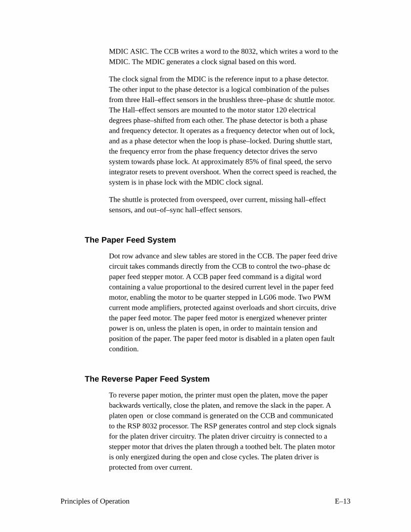
E–13Principles of Operation
MDIC ASIC. The CCB writes a word to the 8032, which writes a word to the
MDIC. The MDIC generates a clock signal based on this word.
The clock signal from the MDIC is the reference input to a phase detector.
The other input to the phase detector is a logical combination of the pulses
from three Hall–effect sensors in the brushless three–phase dc shuttle motor.The Hall–effect sensors are mounted to the motor stator 120 electrical
degrees phase–shifted from each other. The phase detector is both a phase
and frequency detector. It operates as a frequency detector when out of lock,
and as a phase detector when the loop is phase–locked. During shuttle start,
the frequency error from the phase frequency detector drives the servo
system towards phase lock. At approximately 85% of final speed, the servo
integrator resets to prevent overshoot. When the correct speed is reached, the
system is in phase lock with the MDIC clock signal.
The shuttle is protected from overspeed, over current, missing hall–effect
sensors, and out–of–sync hall–effect sensors.
The Paper Feed System
Dot row advance and slew tables are stored in the CCB. The paper feed drive
circuit takes commands directly from the CCB to control the two–phase dc
paper feed stepper motor. A CCB paper feed command is a digital word
containing a value proportional to the desired current level in the paper feed
motor, enabling the motor to be quarter stepped in LG06 mode. Two PWM
current mode amplifiers, protected against overloads and short circuits, drive
the paper feed motor. The paper feed motor is energized whenever printer
power is on, unless the platen is open, in order to maintain tension and
position of the paper. The paper feed motor is disabled in a platen open faultcondition.
The Reverse Paper Feed System
To reverse paper motion, the printer must open the platen, move the paper
backwards vertically, close the platen, and remove the slack in the paper. A
platen open or close command is generated on the CCB and communicated
to the RSP 8032 processor. The RSP generates control and step clock signals
for the platen driver circuitry. The platen driver circuitry is connected to a
stepper motor that drives the platen through a toothed belt. The platen motor
is only energized during the open and close cycles. The platen driver is
protected from over current.
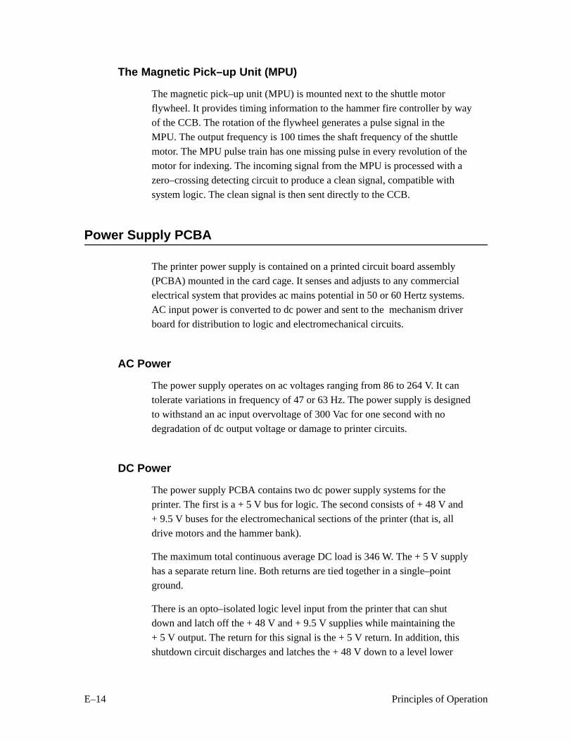
E–14 Principles of Operation
The Magnetic Pick–up Unit (MPU)
The magnetic pick–up unit (MPU) is mounted next to the shuttle motor
flywheel. It provides timing information to the hammer fire controller by wayof the CCB. The rotation of the flywheel generates a pulse signal in the
MPU. The output frequency is 100 times the shaft frequency of the shuttle
motor. The MPU pulse train has one missing pulse in every revolution of the
motor for indexing. The incoming signal from the MPU is processed with a
zero–crossing detecting circuit to produce a clean signal, compatible with
system logic. The clean signal is then sent directly to the CCB.
Power Supply PCBA
The printer power supply is contained on a printed circuit board assembly
(PCBA) mounted in the card cage. It senses and adjusts to any commercial
electrical system that provides ac mains potential in 50 or 60 Hertz systems.
AC input power is converted to dc power and sent to the mechanism driver
board for distribution to logic and electromechanical circuits.
AC Power
The power supply operates on ac voltages ranging from 86 to 264 V. It can
tolerate variations in frequency of 47 or 63 Hz. The power supply is designed
to withstand an ac input overvoltage of 300 Vac for one second with no
degradation of dc output voltage or damage to printer circuits.
DC Power
The power supply PCBA contains two dc power supply systems for the
printer. The first is a + 5 V bus for logic. The second consists of + 48 V and
+ 9.5 V buses for the electromechanical sections of the printer (that is, all
drive motors and the hammer bank).
The maximum total continuous average DC load is 346 W. The + 5 V supply
has a separate return line. Both returns are tied together in a single–point
ground.
There is an opto–isolated logic level input from the printer that can shut
down and latch off the + 48 V and + 9.5 V supplies while maintaining the
+ 5 V output. The return for this signal is the + 5 V return. In addition, this
shutdown circuit discharges and latches the + 48 V down to a level lower
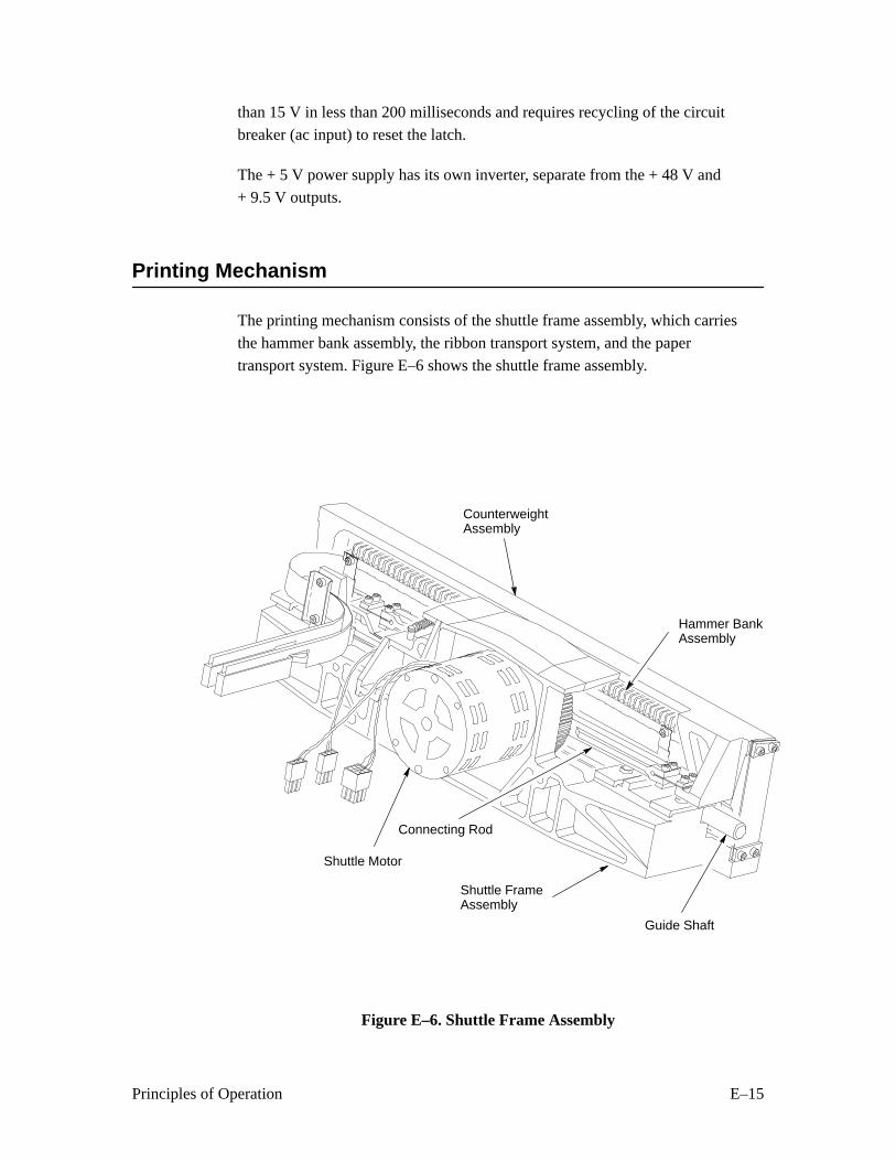
E–15Principles of Operation
than 15 V in less than 200 milliseconds and requires recycling of the circuit
breaker (ac input) to reset the latch.
The + 5 V power supply has its own inverter, separate from the + 48 V and
+ 9.5 V outputs.
Printing Mechanism
The printing mechanism consists of the shuttle frame assembly, which carries
the hammer bank assembly, the ribbon transport system, and the paper
transport system. Figure E–6 shows the shuttle frame assembly.
Shuttle Motor
Hammer BankAssembly
CounterweightAssembly
Shuttle FrameAssembly
Guide Shaft
Connecting Rod
Figure E–6. Shuttle Frame Assembly
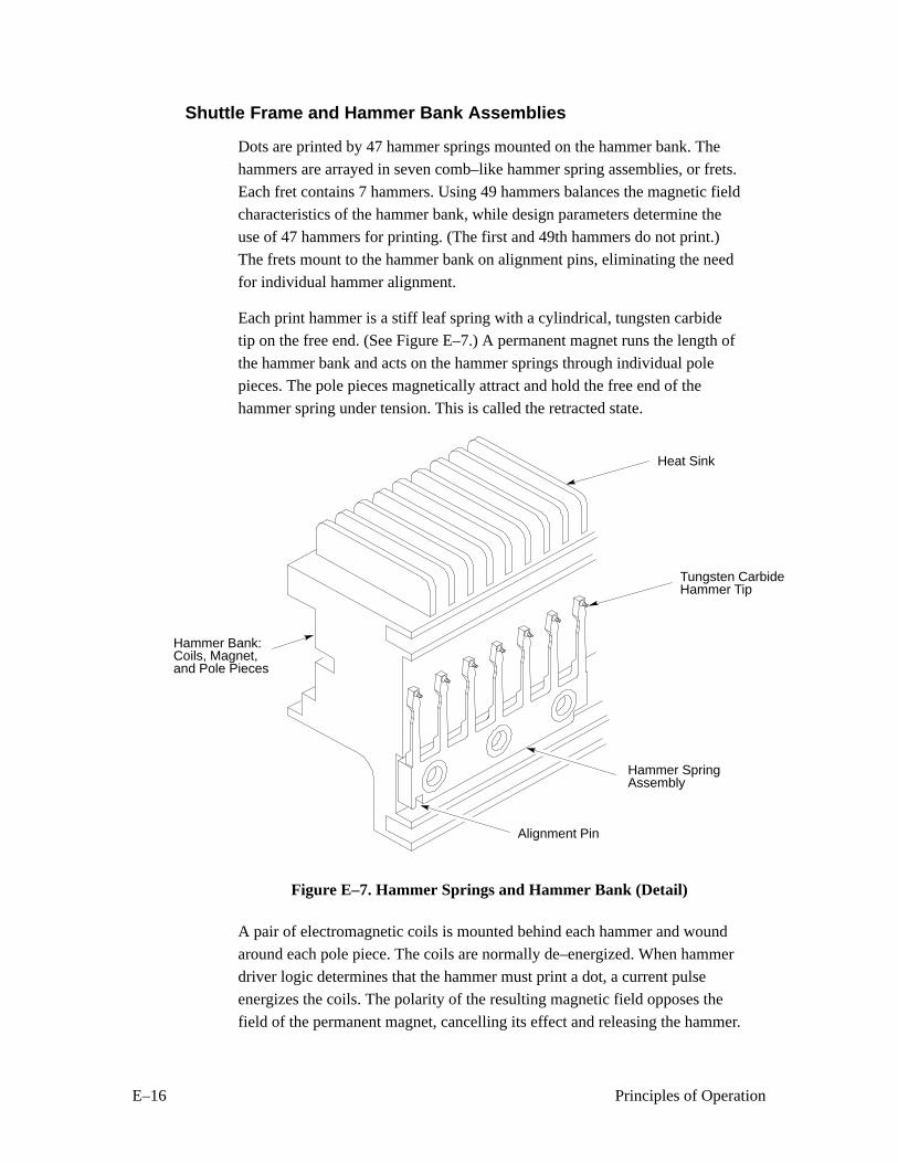
E–16 Principles of Operation
Shuttle Frame and Hammer Bank Assemblies
Dots are printed by 47 hammer springs mounted on the hammer bank. The
hammers are arrayed in seven comb–like hammer spring assemblies, or frets.
Each fret contains 7 hammers. Using 49 hammers balances the magnetic field
characteristics of the hammer bank, while design parameters determine the
use of 47 hammers for printing. (The first and 49th hammers do not print.)
The frets mount to the hammer bank on alignment pins, eliminating the need
for individual hammer alignment.
Each print hammer is a stiff leaf spring with a cylindrical, tungsten carbide
tip on the free end. (See Figure E–7.) A permanent magnet runs the length of
the hammer bank and acts on the hammer springs through individual pole
pieces. The pole pieces magnetically attract and hold the free end of the
hammer spring under tension. This is called the retracted state.
Hammer Bank:Coils, Magnet,and Pole Pieces
Alignment Pin
Hammer SpringAssembly
Tungsten CarbideHammer Tip
Heat Sink
Figure E–7. Hammer Springs and Hammer Bank (Detail)
A pair of electromagnetic coils is mounted behind each hammer and wound
around each pole piece. The coils are normally de–energized. When hammer
driver logic determines that the hammer must print a dot, a current pulse
energizes the coils. The polarity of the resulting magnetic field opposes the
field of the permanent magnet, cancelling its effect and releasing the hammer.
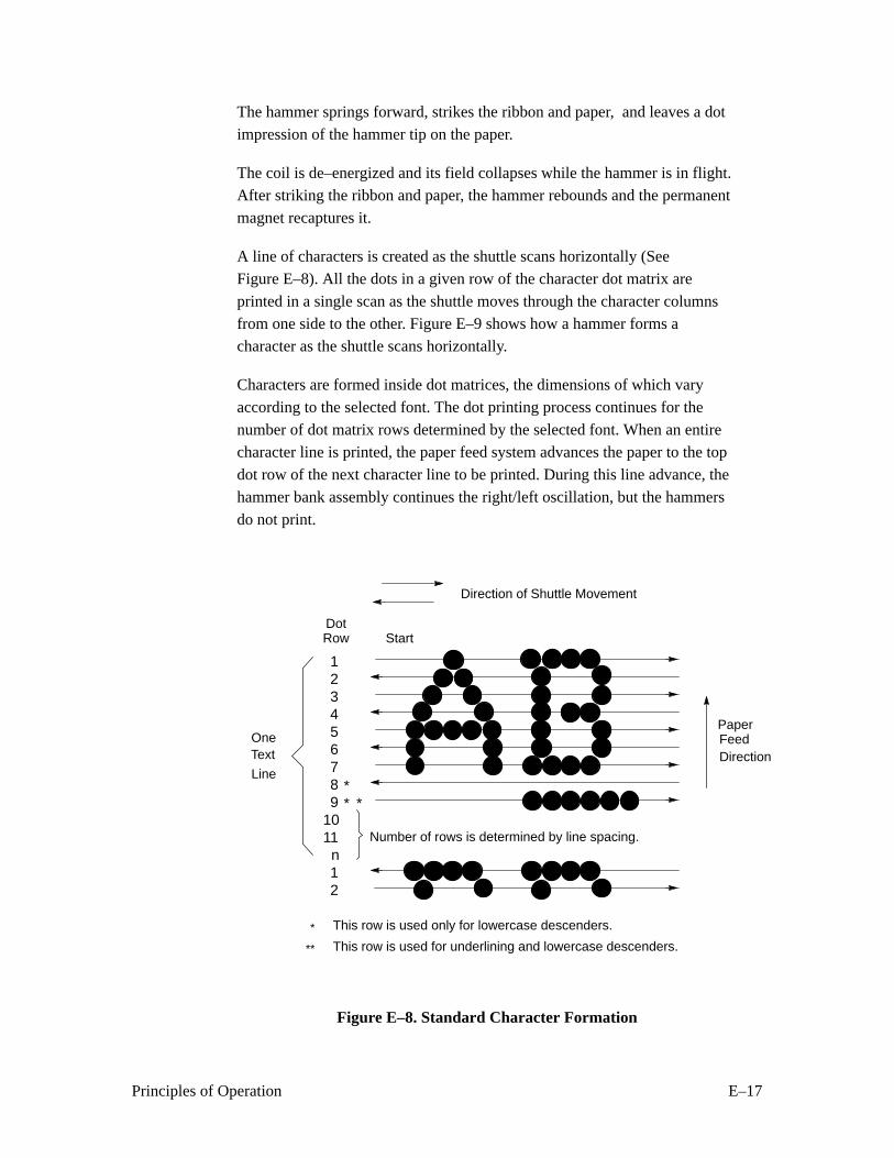
E–17Principles of Operation
The hammer springs forward, strikes the ribbon and paper, and leaves a dot
impression of the hammer tip on the paper.
The coil is de–energized and its field collapses while the hammer is in flight.After striking the ribbon and paper, the hammer rebounds and the permanent
magnet recaptures it.
A line of characters is created as the shuttle scans horizontally (See
Figure E–8). All the dots in a given row of the character dot matrix are
printed in a single scan as the shuttle moves through the character columnsfrom one side to the other. Figure E–9 shows how a hammer forms a
character as the shuttle scans horizontally.
Characters are formed inside dot matrices, the dimensions of which vary
according to the selected font. The dot printing process continues for the
number of dot matrix rows determined by the selected font. When an entirecharacter line is printed, the paper feed system advances the paper to the top
dot row of the next character line to be printed. During this line advance, the
hammer bank assembly continues the right/left oscillation, but the hammers
do not print.
DotRow Start
PaperFeed
Number of rows is determined by line spacing.
123456789
1011
n12
** *
This row is used only for lowercase descenders.
This row is used for underlining and lowercase descenders.
*
**
OneText
Line
Direction of Shuttle Movement
Direction
Figure E–8. Standard Character Formation
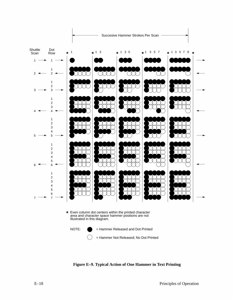
E–18 Principles of Operation
* * * * * *1 1 3 1 3 5 1 3 5 7 1 3 5 7 9
1234567
123456
12345
123
4
12
1
7
6
5
3
4
2
1
123
*
NOTE: = Hammer Released and Dot Printed
= Hammer Not Released; No Dot Printed
ShuttleScan
DotRow
Succesive Hammer Strokes Per Scan
Even column dot centers within the printed characterarea and character space hammer positions are notillustrated in this diagram.
Figure E–9. Typical Action of One Hammer in Text Printing
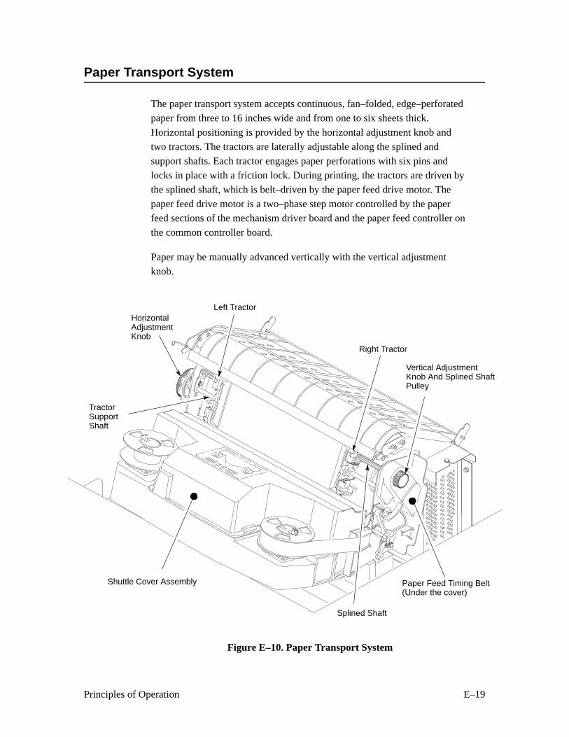
E–19Principles of Operation
Paper Transport System
The paper transport system accepts continuous, fan–folded, edge–perforated
paper from three to 16 inches wide and from one to six sheets thick.
Horizontal positioning is provided by the horizontal adjustment knob and
two tractors. The tractors are laterally adjustable along the splined and
support shafts. Each tractor engages paper perforations with six pins and
locks in place with a friction lock. During printing, the tractors are driven by
the splined shaft, which is belt–driven by the paper feed drive motor. The
paper feed drive motor is a two–phase step motor controlled by the paperfeed sections of the mechanism driver board and the paper feed controller on
the common controller board.
Paper may be manually advanced vertically with the vertical adjustment
knob.
Right Tractor
Vertical AdjustmentKnob And Splined ShaftPulley
Paper Feed Timing Belt(Under the cover)
Splined Shaft
Shuttle Cover Assembly
TractorSupportShaft
HorizontalAdjustmentKnob
Left Tractor
Figure E–10. Paper Transport System
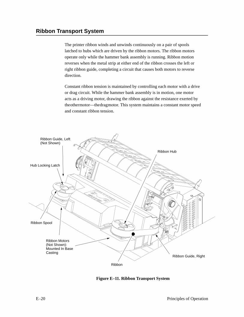
E–20 Principles of Operation
Ribbon Transport System
The printer ribbon winds and unwinds continuously on a pair of spools
latched to hubs which are driven by the ribbon motors. The ribbon motors
operate only while the hammer bank assembly is running. Ribbon motion
reverses when the metal strip at either end of the ribbon crosses the left or
right ribbon guide, completing a circuit that causes both motors to reversedirection.
Constant ribbon tension is maintained by controlling each motor with a driveor drag circuit. While the hammer bank assembly is in motion, one motor
acts as a driving motor, drawing the ribbon against the resistance exerted by
the other motor—the drag motor. This system maintains a constant motor speed
and constant ribbon tension.
Ribbon Guide, Right
Hub Locking Latch
Ribbon Guide, Left(Not Shown)
Ribbon Spool
Ribbon Motors(Not Shown):Mounted In BaseCasting
Ribbon Hub
Ribbon
Figure E–11. Ribbon Transport System

F–1Ferrite Noise Suppression Cores
F Ferrite Noise Suppression Cores
Ferrite cores reduce radio frequency interference (RFI) with electronic
equipment located near the printer.
Two kinds of ferrite cores are used in the printer:
1. Cylindrical cores—Cables pass through the core or are wound around it.
2. Block cores—The core is housed in a hinged plastic case. Cables are laid in a
groove in the core, and the plastic case is closed, securing the core to the
cable.
Figure F–1 shows the location of the ferrite cores in the LG06 printer.
IMPORTANT
When removing cables that pass through or around ferrite cores, notethe number of times the cable is wound around the core. You mustduplicate these windings when you replace the cable. Use Figure F–1 asyour guide.
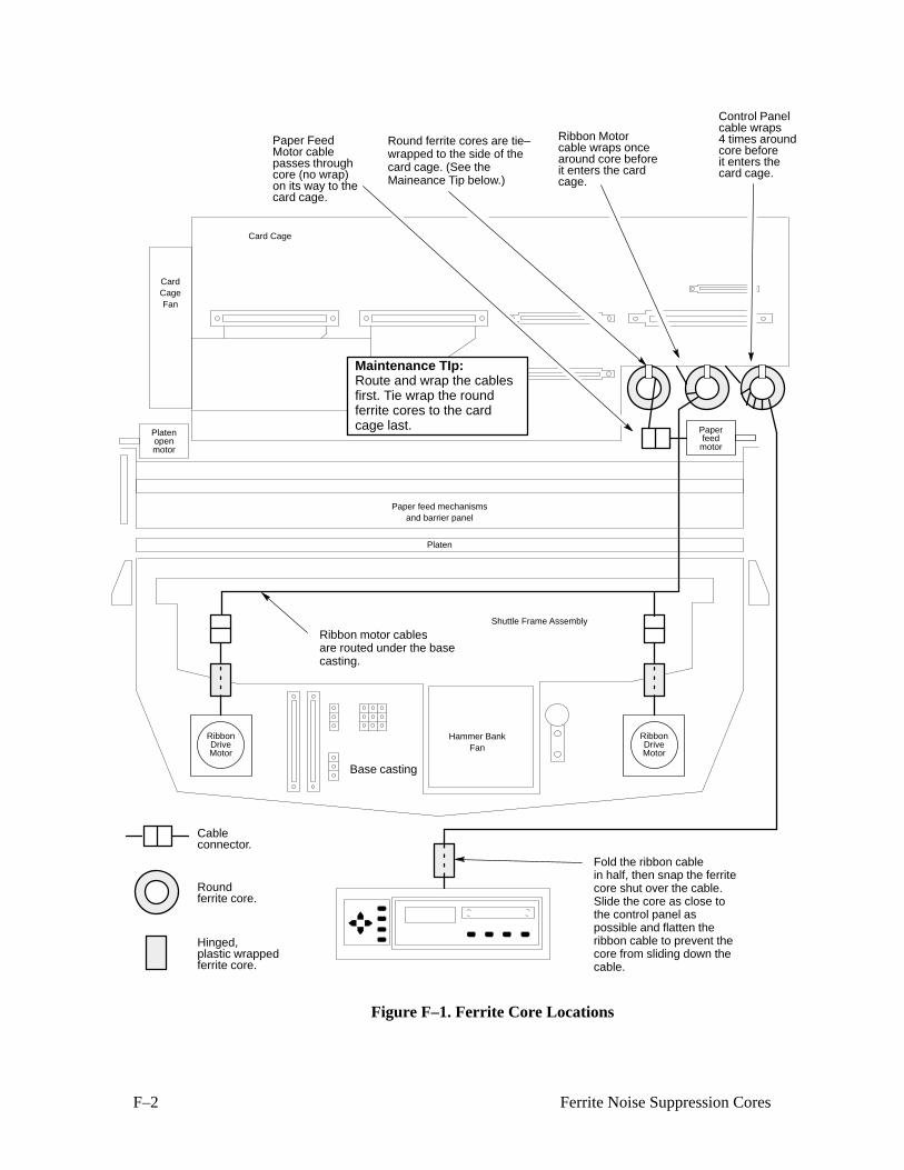
F–2 Ferrite Noise Suppression Cores
Card Cage
Shuttle Frame Assembly
Hammer BankFan
CardCageFan
Paper feed mechanismsand barrier panel
Platen
Base casting
Platenopenmotor
Paperfeed
motor
RibbonDriveMotor
RibbonDriveMotor
Paper FeedMotor cablepasses throughcore (no wrap)on its way to thecard cage.
Hinged,plastic wrappedferrite core.
Roundferrite core.
Cableconnector.
Ribbon Motorcable wraps oncearound core beforeit enters the cardcage.
Maintenance TIp:Route and wrap the cablesfirst. Tie wrap the roundferrite cores to the cardcage last.
Round ferrite cores are tie–wrapped to the side of thecard cage. (See theMaineance Tip below.)
Ribbon motor cablesare routed under the basecasting.
Control Panelcable wraps4 times around
card cage.
Fold the ribbon cablein half, then snap the ferritecore shut over the cable.Slide the core as close tothe control panel aspossible and flatten theribbon cable to prevent thecore from sliding down thecable.
core beforeit enters the
Figure F–1. Ferrite Core Locations
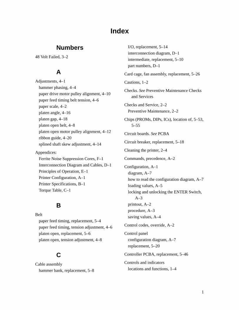
1
Index
Numbers48 Volt Failed, 3–2
AAdjustments, 4–1
hammer phasing, 4–4
paper drive motor pulley alignment, 4–10
paper feed timing belt tension, 4–6
paper scale, 4–2
platen angle, 4–16
platen gap, 4–18
platen open belt, 4–8
platen open motor pulley alignment, 4–12
ribbon guide, 4–20
splined shaft skew adjustment, 4–14
Appendices:
Ferrite Noise Suppression Cores, F–1
Interconnection Diagram and Cables, D–1
Principles of Operation, E–1
Printer Configuration, A–1
Printer Specifications, B–1
Torque Table, C–1
BBelt
paper feed timing, replacement, 5–4
paper feed timing, tension adjustment, 4–6
platen open, replacement, 5–6
platen open, tension adjustment, 4–8
CCable assembly
hammer bank, replacement, 5–8
I/O, replacement, 5–14
interconnection diagram, D–1
intermediate, replacement, 5–10
part numbers, D–1
Card cage, fan assembly, replacement, 5–26
Cautions, 1–2
Checks. See Preventive Maintenance Checks
and Services
Checks and Service, 2–2
Preventive Maintenance, 2–2
Chips (PROMs, DIPs, ICs), location of, 5–53,
5–55
Circuit boards. See PCBA
Circuit breaker, replacement, 5–18
Cleaning the printer, 2–4
Commands, precedence, A–2
Configuration, A–1
diagram, A–7
how to read the configuration diagram, A–7
loading values, A–5
locking and unlocking the ENTER Switch,
A–3
printout, A–2
procedure, A–3
saving values, A–4
Control codes, override, A–2
Control panel
configuration diagram, A–7
replacement, 5–20
Controller PCBA, replacement, 5–46
Controls and indicators
locations and functions, 1–4
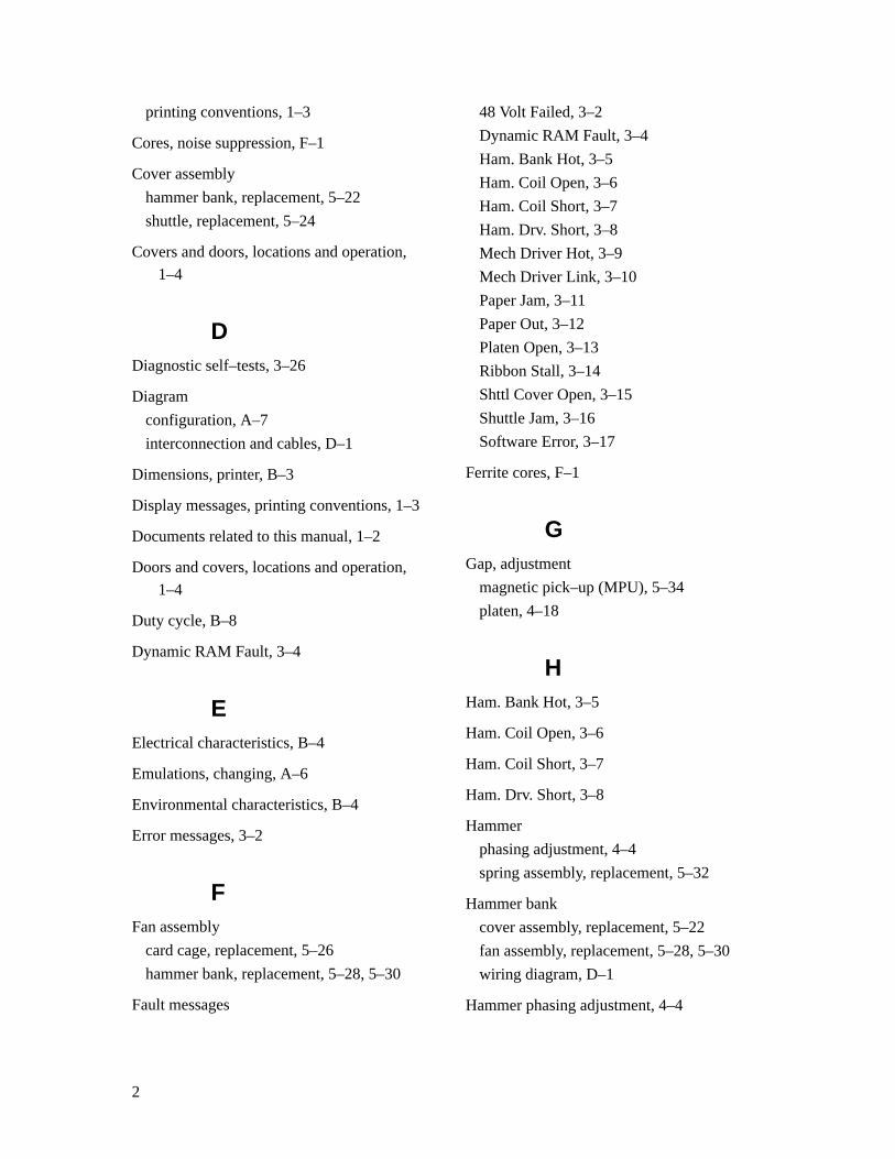
2
printing conventions, 1–3
Cores, noise suppression, F–1
Cover assembly
hammer bank, replacement, 5–22
shuttle, replacement, 5–24
Covers and doors, locations and operation,
1–4
DDiagnostic self–tests, 3–26
Diagram
configuration, A–7
interconnection and cables, D–1
Dimensions, printer, B–3
Display messages, printing conventions, 1–3
Documents related to this manual, 1–2
Doors and covers, locations and operation,
1–4
Duty cycle, B–8
Dynamic RAM Fault, 3–4
EElectrical characteristics, B–4
Emulations, changing, A–6
Environmental characteristics, B–4
Error messages, 3–2
FFan assembly
card cage, replacement, 5–26
hammer bank, replacement, 5–28, 5–30
Fault messages
48 Volt Failed, 3–2
Dynamic RAM Fault, 3–4
Ham. Bank Hot, 3–5
Ham. Coil Open, 3–6
Ham. Coil Short, 3–7
Ham. Drv. Short, 3–8
Mech Driver Hot, 3–9
Mech Driver Link, 3–10
Paper Jam, 3–11
Paper Out, 3–12
Platen Open, 3–13
Ribbon Stall, 3–14
Shttl Cover Open, 3–15
Shuttle Jam, 3–16
Software Error, 3–17
Ferrite cores, F–1
GGap, adjustment
magnetic pick–up (MPU), 5–34
platen, 4–18
HHam. Bank Hot, 3–5
Ham. Coil Open, 3–6
Ham. Coil Short, 3–7
Ham. Drv. Short, 3–8
Hammer
phasing adjustment, 4–4
spring assembly, replacement, 5–32
Hammer bank
cover assembly, replacement, 5–22
fan assembly, replacement, 5–28, 5–30
wiring diagram, D–1
Hammer phasing adjustment, 4–4
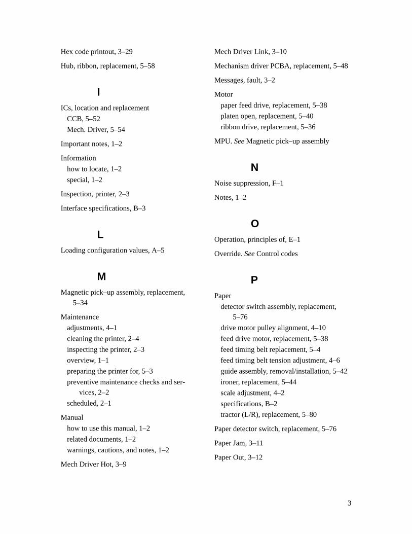
3
Hex code printout, 3–29
Hub, ribbon, replacement, 5–58
IICs, location and replacement
CCB, 5–52
Mech. Driver, 5–54
Important notes, 1–2
Information
how to locate, 1–2
special, 1–2
Inspection, printer, 2–3
Interface specifications, B–3
LLoading configuration values, A–5
MMagnetic pick–up assembly, replacement,
5–34
Maintenance
adjustments, 4–1
cleaning the printer, 2–4
inspecting the printer, 2–3
overview, 1–1
preparing the printer for, 5–3
preventive maintenance checks and ser-
vices, 2–2
scheduled, 2–1
Manual
how to use this manual, 1–2
related documents, 1–2
warnings, cautions, and notes, 1–2
Mech Driver Hot, 3–9
Mech Driver Link, 3–10
Mechanism driver PCBA, replacement, 5–48
Messages, fault, 3–2
Motor
paper feed drive, replacement, 5–38
platen open, replacement, 5–40
ribbon drive, replacement, 5–36
MPU. See Magnetic pick–up assembly
NNoise suppression, F–1
Notes, 1–2
OOperation, principles of, E–1
Override. See Control codes
PPaper
detector switch assembly, replacement,
5–76
drive motor pulley alignment, 4–10
feed drive motor, replacement, 5–38
feed timing belt replacement, 5–4
feed timing belt tension adjustment, 4–6
guide assembly, removal/installation, 5–42
ironer, replacement, 5–44
scale adjustment, 4–2
specifications, B–2
tractor (L/R), replacement, 5–80
Paper detector switch, replacement, 5–76
Paper Jam, 3–11
Paper Out, 3–12
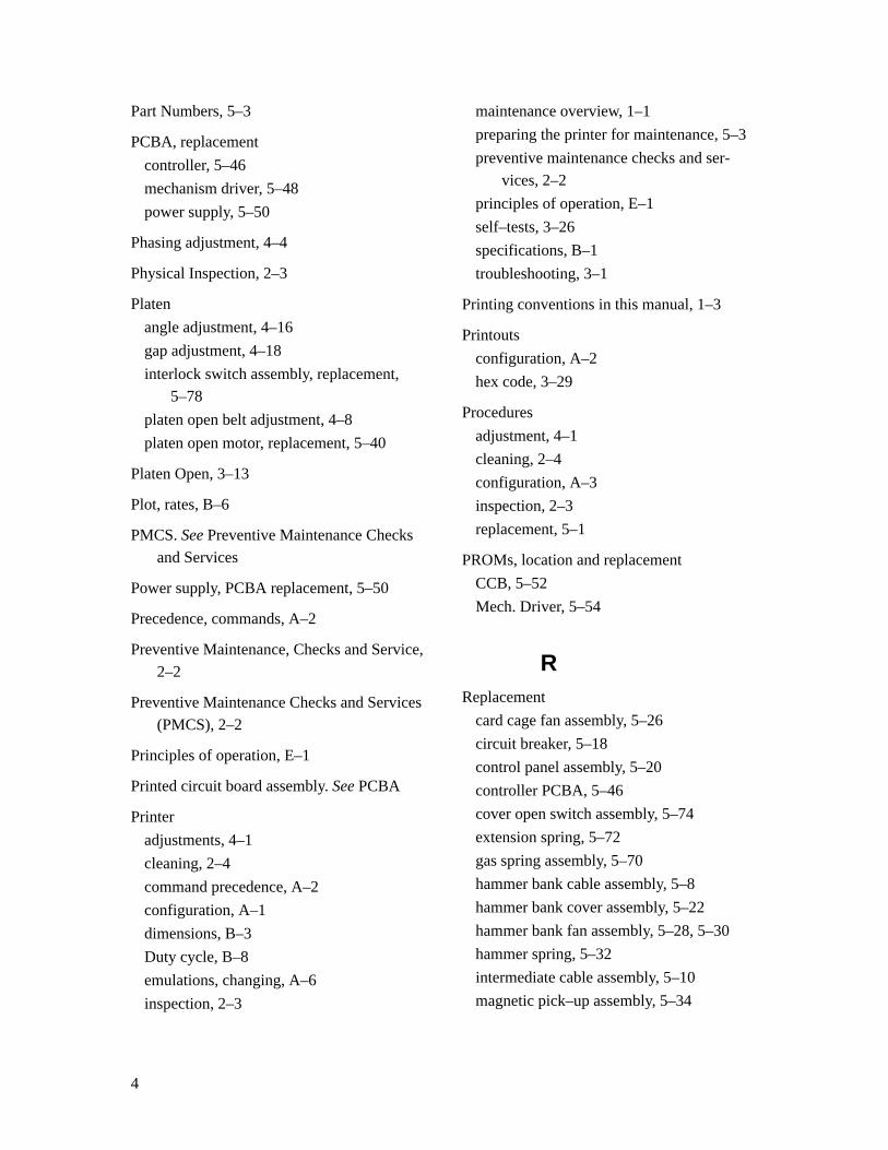
4
Part Numbers, 5–3
PCBA, replacement
controller, 5–46
mechanism driver, 5–48
power supply, 5–50
Phasing adjustment, 4–4
Physical Inspection, 2–3
Platen
angle adjustment, 4–16
gap adjustment, 4–18
interlock switch assembly, replacement,
5–78
platen open belt adjustment, 4–8
platen open motor, replacement, 5–40
Platen Open, 3–13
Plot, rates, B–6
PMCS. See Preventive Maintenance Checks
and Services
Power supply, PCBA replacement, 5–50
Precedence, commands, A–2
Preventive Maintenance, Checks and Service,
2–2
Preventive Maintenance Checks and Services
(PMCS), 2–2
Principles of operation, E–1
Printed circuit board assembly. See PCBA
Printer
adjustments, 4–1
cleaning, 2–4
command precedence, A–2
configuration, A–1
dimensions, B–3
Duty cycle, B–8
emulations, changing, A–6
inspection, 2–3
maintenance overview, 1–1
preparing the printer for maintenance, 5–3
preventive maintenance checks and ser-
vices, 2–2
principles of operation, E–1
self–tests, 3–26
specifications, B–1
troubleshooting, 3–1
Printing conventions in this manual, 1–3
Printouts
configuration, A–2
hex code, 3–29
Procedures
adjustment, 4–1
cleaning, 2–4
configuration, A–3
inspection, 2–3
replacement, 5–1
PROMs, location and replacement
CCB, 5–52
Mech. Driver, 5–54
RReplacement
card cage fan assembly, 5–26
circuit breaker, 5–18
control panel assembly, 5–20
controller PCBA, 5–46
cover open switch assembly, 5–74
extension spring, 5–72
gas spring assembly, 5–70
hammer bank cable assembly, 5–8
hammer bank cover assembly, 5–22
hammer bank fan assembly, 5–28, 5–30
hammer spring, 5–32
intermediate cable assembly, 5–10
magnetic pick–up assembly, 5–34
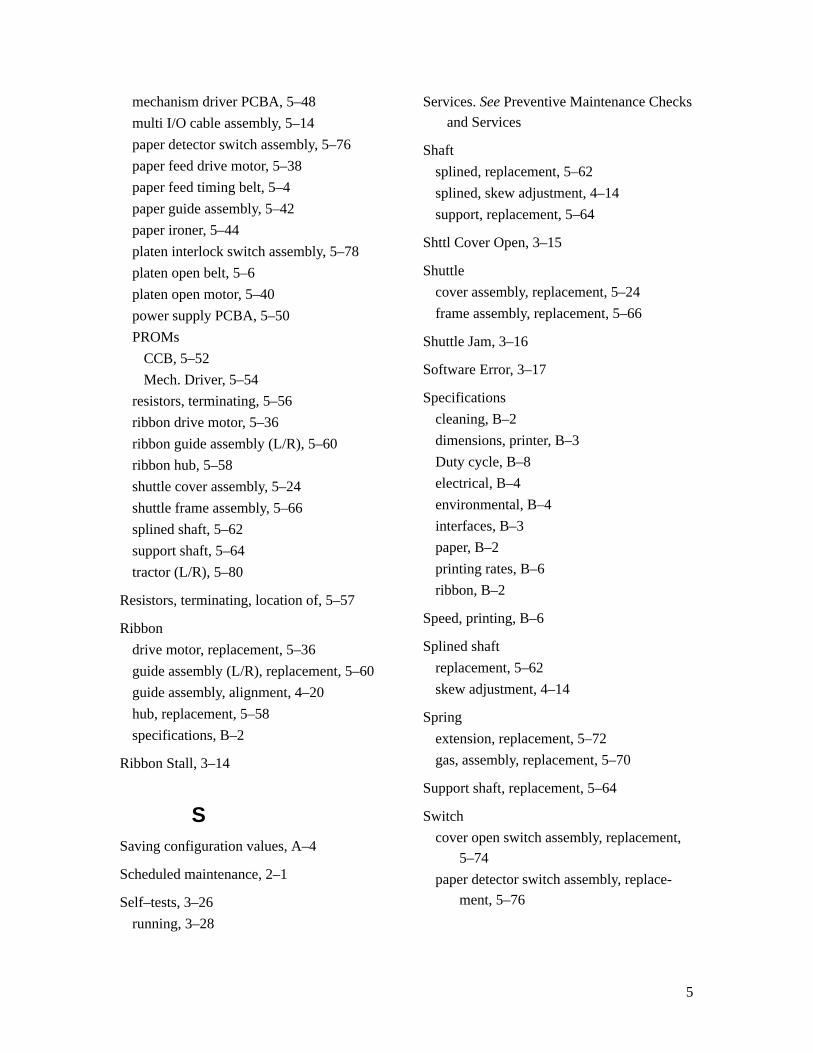
5
mechanism driver PCBA, 5–48
multi I/O cable assembly, 5–14
paper detector switch assembly, 5–76
paper feed drive motor, 5–38
paper feed timing belt, 5–4
paper guide assembly, 5–42
paper ironer, 5–44
platen interlock switch assembly, 5–78
platen open belt, 5–6
platen open motor, 5–40
power supply PCBA, 5–50
PROMs
CCB, 5–52
Mech. Driver, 5–54
resistors, terminating, 5–56
ribbon drive motor, 5–36
ribbon guide assembly (L/R), 5–60
ribbon hub, 5–58
shuttle cover assembly, 5–24
shuttle frame assembly, 5–66
splined shaft, 5–62
support shaft, 5–64
tractor (L/R), 5–80
Resistors, terminating, location of, 5–57
Ribbon
drive motor, replacement, 5–36
guide assembly (L/R), replacement, 5–60
guide assembly, alignment, 4–20
hub, replacement, 5–58
specifications, B–2
Ribbon Stall, 3–14
SSaving configuration values, A–4
Scheduled maintenance, 2–1
Self–tests, 3–26
running, 3–28
Services. See Preventive Maintenance Checks
and Services
Shaft
splined, replacement, 5–62
splined, skew adjustment, 4–14
support, replacement, 5–64
Shttl Cover Open, 3–15
Shuttle
cover assembly, replacement, 5–24
frame assembly, replacement, 5–66
Shuttle Jam, 3–16
Software Error, 3–17
Specifications
cleaning, B–2
dimensions, printer, B–3
Duty cycle, B–8
electrical, B–4
environmental, B–4
interfaces, B–3
paper, B–2
printing rates, B–6
ribbon, B–2
Speed, printing, B–6
Splined shaft
replacement, 5–62
skew adjustment, 4–14
Spring
extension, replacement, 5–72
gas, assembly, replacement, 5–70
Support shaft, replacement, 5–64
Switch
cover open switch assembly, replacement,
5–74
paper detector switch assembly, replace-
ment, 5–76
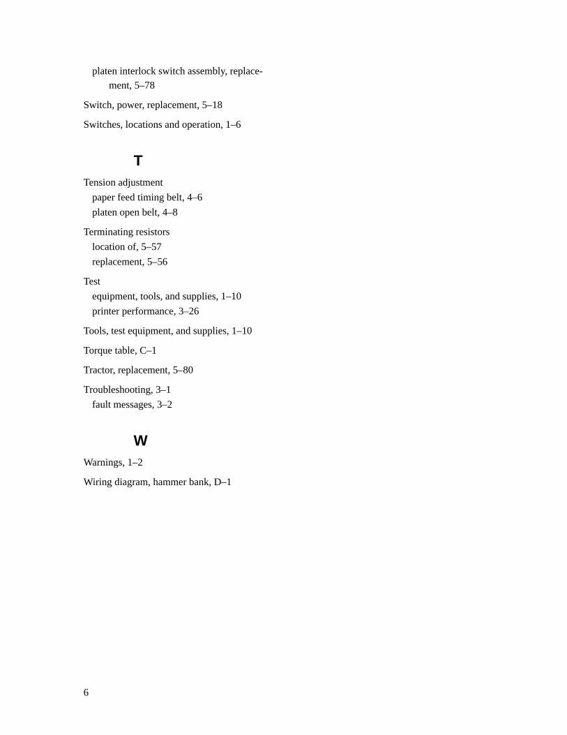
6
platen interlock switch assembly, replace-
ment, 5–78
Switch, power, replacement, 5–18
Switches, locations and operation, 1–6
TTension adjustment
paper feed timing belt, 4–6
platen open belt, 4–8
Terminating resistors
location of, 5–57
replacement, 5–56
Test
equipment, tools, and supplies, 1–10
printer performance, 3–26
Tools, test equipment, and supplies, 1–10
Torque table, C–1
Tractor, replacement, 5–80
Troubleshooting, 3–1
fault messages, 3–2
WWarnings, 1–2
Wiring diagram, hammer bank, D–1

![IEEE TRANSACTIONS ON MOBILE COMPUTING, VOL. 5, NO. 9 ...users.cecs.anu.edu.au/~Weifa.Liang/papers/LG06.pdf · wired networks [26]. However, as they mentioned, energy efficient routing](https://img.pdfslide.net/doc/110x75/60344e2410473f65ae4896f6/ieee-transactions-on-mobile-computing-vol-5-no-9-userscecsanueduauweifaliangpaperslg06pdf.jpg)