Embed Size (px)
Citation preview
USER’S MANUAL
LILY Self-Leveling Borehole Tiltmeter
Serial No.___________
Part no. 98020-01 (RS485 Output, 6-Pin Connector) Part no. 98020-02 (RS232 Output, 6-Pin Connector) Part no. 98020-03 (RS485 + RS232 Outputs, 8-Pin Connector)
1336 Brommer Street Santa Cruz, CA 95062 USA
Tel (831) 462-2801 Fax (831) 462-4418
[email protected] www.geomechanics.com
Copyright ©2007 by Applied Geomechanics Inc. All rights reserved. Manual No. B-05-1003, Rev. D
TABLE OF CONTENTS
1 Introduction..............................................................................................................................1
2 Technical Highlights ................................................................................................................2
3 Specifications ............................................................................................................................3
4 Transient Protection ................................................................................................................3
5 Digital Output Features and Wiring ......................................................................................4
5.1 RS232 Output .....................................................................................................................4
5.2 RS485 (RS422) Output.......................................................................................................4
5.3 Using the Test Cable..........................................................................................................4
6 Initial Check-Out Procedures...............................................................................................10
7 Installing and Leveling Your Tiltmeter, Collecting Data...................................................10
7.1 Settling Behavior..............................................................................................................11
8 Communicating with your LILY Tiltmeter..........................................................................11
8.1 Basic Requirements and Settings .....................................................................................11
8.2 Firmware Command Format ...........................................................................................12
8.3 Firmware Command Summary ........................................................................................13
8.4 Sample Data Using the XY Command .............................................................................16
8.5 Using the Magnetic Compass ..........................................................................................17
8.6 Recording Data in Internal Memory or on a PC; Data File Sizes ..................................18
8.7 Switching between RS232 and RS485 Output..................................................................18
9 Maintenance and Troubleshooting.......................................................................................18
9.1 Routine Maintenance .......................................................................................................18
9.2 Determining the Cause of Malfunctions ..........................................................................19
9.3 Opening Your LILY Tiltmeter..........................................................................................19
Appendix A Connector Pin Assignments and Test Cable Wiring ......................................20
Appendix B Firmware Commands........................................................................................22
Appendix C Warranty and Limitation of Liability..............................................................39
B-05-1003, Rev. D
1 Introduction
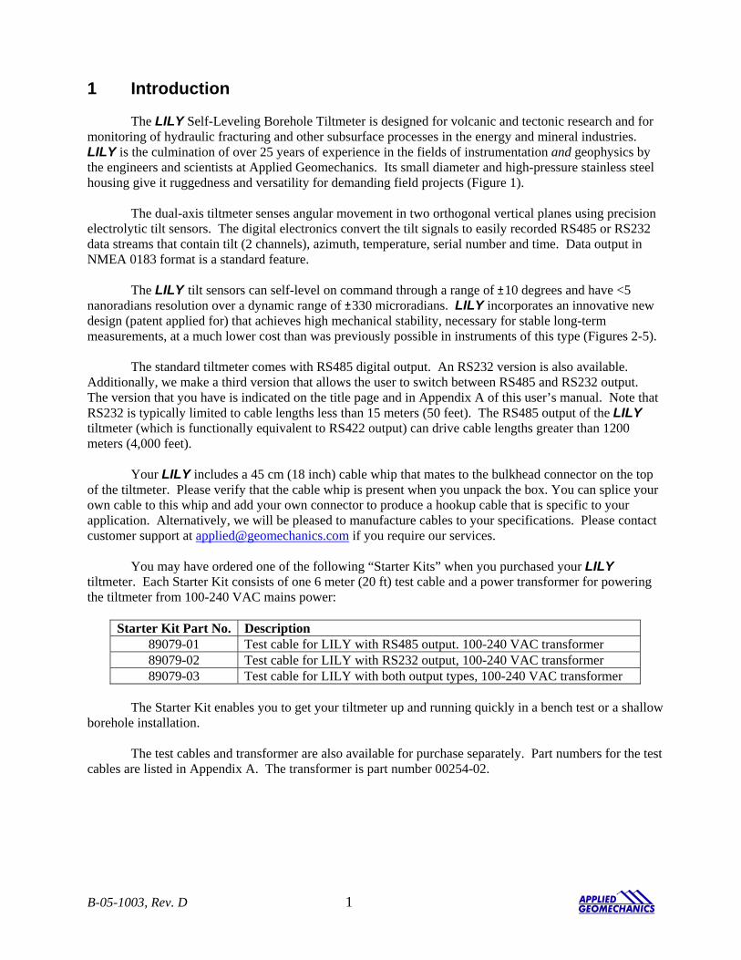
The LILY Self-Leveling Borehole Tiltmeter is designed for volcanic and tectonic research and for monitoring of hydraulic fracturing and other subsurface processes in the energy and mineral industries. LILY is the culmination of over 25 years of experience in the fields of instrumentation and geophysics by the engineers and scientists at Applied Geomechanics. Its small diameter and high-pressure stainless steel housing give it ruggedness and versatility for demanding field projects (Figure 1).
The dual-axis tiltmeter senses angular movement in two orthogonal vertical planes using precision electrolytic tilt sensors. The digital electronics convert the tilt signals to easily recorded RS485 or RS232 data streams that contain tilt (2 channels), azimuth, temperature, serial number and time. Data output in NMEA 0183 format is a standard feature.
The LILY tilt sensors can self-level on command through a range of ±10 degrees and have <5 nanoradians resolution over a dynamic range of ±330 microradians. LILY incorporates an innovative new design (patent applied for) that achieves high mechanical stability, necessary for stable long-term measurements, at a much lower cost than was previously possible in instruments of this type (Figures 2-5).
The standard tiltmeter comes with RS485 digital output. An RS232 version is also available. Additionally, we make a third version that allows the user to switch between RS485 and RS232 output. The version that you have is indicated on the title page and in Appendix A of this user’s manual. Note that RS232 is typically limited to cable lengths less than 15 meters (50 feet). The RS485 output of the LILY tiltmeter (which is functionally equivalent to RS422 output) can drive cable lengths greater than 1200 meters (4,000 feet).
Your LILY includes a 45 cm (18 inch) cable whip that mates to the bulkhead connector on the top of the tiltmeter. Please verify that the cable whip is present when you unpack the box. You can splice your own cable to this whip and add your own connector to produce a hookup cable that is specific to your application. Alternatively, we will be pleased to manufacture cables to your specifications. Please contact customer support at [email protected] if you require our services.
You may have ordered one of the following “Starter Kits” when you purchased your LILY tiltmeter. Each Starter Kit consists of one 6 meter (20 ft) test cable and a power transformer for powering the tiltmeter from 100-240 VAC mains power:
Starter Kit Part No. Description 89079-01 Test cable for LILY with RS485 output. 100-240 VAC transformer 89079-02 Test cable for LILY with RS232 output, 100-240 VAC transformer 89079-03 Test cable for LILY with both output types, 100-240 VAC transformer
The Starter Kit enables you to get your tiltmeter up and running quickly in a bench test or a shallow
borehole installation. The test cables and transformer are also available for purchase separately. Part numbers for the test
cables are listed in Appendix A. The transformer is part number 00254-02.
B-05-1003, Rev. D 1
Figure 1. LILY Self-Leveling Borehole Tiltmeter 2 Technical Highlights LILY includes the following key features:
• Tilt angle is measured with two electrolytic sensors with resolution < 5 nanoradians.
• The tiltmeter will automatically level both sensors upon receipt of one firmware command.
• An onboard magnetic compass measures tiltmeter azimuth.
• The tiltmeter comes with a powerful set of user-selectable firmware commands.
• All electronics reside on a single internal printed-circuit board.
• Housing and all structural elements are nonmagnetic stainless steel. The housing is designed for rapid assembly and for full submergence at high water pressures (Figure 3).
• All tiltmeters are hand-assembled, calibrated, and tested at our plant under stringent quality control standards.
• AGI maintains complete specifications and test records for every tiltmeter built. Your tiltmeter contains two electrolytic level sensors (one for each tilt axis) that produce changes in resistance in response to a rotation of the sensor. A voltage divider network senses the resistance change. The electronics then sample and convert the sensor outputs into tilt angles using factory calibration data stored in nonvolatile FLASH memory. LILY measure tilts in two orthogonal vertical planes, X and Y
B-05-1003, Rev. D 2
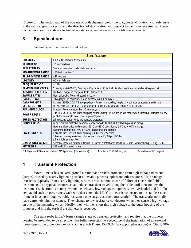
(Figure 6). The vector sum of the outputs of both channels yields the magnitude of rotation with reference to the vertical gravity vector and the direction of this rotation with respect to the tiltmeter azimuth. Please contact us should you desire technical assistance when processing your tilt measurements. 3 Specifications
General specifications are listed below:
Specifications CHANNELS X tilt, Y tilt, azimuth, temperature RESOLUTION < 5 nanoradians REPEATABILITY Same as resolution under static conditions MEASUREMENT RANGE ±330 microradians* SELF-LEVELING RANGE ±10 degrees LINEARITY 0.2% of full span FREQ. RESPONSE < 1 Hz TEMPERATURE COEFS. Span: KS = +0.02%/°C, Zero: KZ = ±3 µradians/°C, typical. Smaller coefficients available at higher cost. AZIMUTH DETECTION On-board magnetic compass, 0° to 360° output SAMPLE RATES User-selectable from 10/second to 1/day DATA STORAGE 2 Megabytes of nonvolatile Flash memory (64,000 samples) DATA FORMATS Formats: NMEA XDR, Trimble proprietary, Ashtech compatible, Simple (x, y, azimuth, temperature, serial no.) SERIAL OUTPUT RS232 or RS485 (RS422). Baud rate: 4800, 9600, 19200 (default), 28800, 57600, 115200 REAL-TIME CLOCK Present. Accuracy better than 10 minutes/year.
POWER REQT’S. 7 to 28 VDC @ 30 mA when sampling or transmitting, @16.5 mA in idle mode when sampling 1/minute; 250 mV peak-to-peak ripple max., reverse polarity protected
SURGE PROTECTION All input and output wires are tranzorb protected. CONNECTIONS 6- or 8-pin wet-mateable neoprene connector with 10,000 psi (690 bars) pressure rating
ENVIRONMENTAL
Housing, electronics and sensor: -25°C to +85°C operational, -30°C to +100°C storage Neoprene connector: -4°C to +60°C operational and storage Collapse pressure of tubular housing = 3,300 psi (227 bars). Titanium housing available, collapse pressure = 10,500 psi (725 bars) LILY is fully submersible.
DIMENSION & WEIGHT 51mm (2 inches) diameter x 915mm (36 inches); detachable handle is 150mm (6 inches) long. 6.8 kg (15 lb) MATERIALS 303 and 304 stainless steel * 1 degree = 3600 arc seconds = 17453 µradians (microradians) 1 radian = 57.29578 degrees 2π radians = 360 degrees
4 Transient Protection Your tiltmeter has an earth ground circuit that provides protection from high-voltage transients (surges) caused by nearby lightening strikes, unstable power supplies and other sources. High-voltage transients, typically from nearby lightning strikes, are a common cause of failure of electronic field instruments. In a typical occurrence, an induced transient travels along the cable until it encounters the instrument’s electronic circuitry, where the delicate, low-voltage components are overloaded and fail. To help avoid such an occurrence, each wire that enters the LILY tiltmeter is connected to the stainless steel tiltmeter housing through variable-resistance type surge absorbers (transzorbs). The transzorbs normally have extremely high resistance. They change to low-resistance conductors when they sense a high voltage on one of the incoming wires. Ideally, they will then short this high voltage to the outer housing of the tiltmeter and into the earth if the tiltmeter is grounded. The transzorbs in LILY form a single stage of transient protection and require that the tiltmeter housing be grounded to be effective. For fuller protection, we recommend the installation of an external three-stage surge protection device, such as a PolyPhaser IX-DC24 (www.polyphaser.com) or Citel B480-
B-05-1003, Rev. D 3
B-05-10
03, Rev. D 4
12 (www.citelprotection.com). Transient protection and noise reduction can also be enhanced by keeping your cable as short as possible, and by earthing your cable shield (drain wire) at one end only. Note that the tiltmeter connector does not carry a cable shield into the tiltmeter or short it to the tiltmeter housing. 5 Digital Output Features and Wiring
The firmware in your tiltmeter can be selected to give you either RS232 or RS485 (RS422) digital
output. The test cable shipped with your cable has DB9 connectors for both output protocols. Firmware command XY-SET-RSMODE,x is used to switch between the two protocols. Please read Section 8.7 before attempting to change output protocols.
5.1 RS232 Output
RS232 output is designed for signal transmission over cable lengths less than approximately 15 meters. LILY versions 98020-02 and 98020-03 have RS232 output. Appendix A lists the RS232 pin assignments in the tiltmeter connector and cable.
5.2 RS485 (RS422) Output RS485 and RS422 outputs are designed for signal transmission over long cables. The RS485 and
RS422 standards specify transmission distances up to 1220 meters (4000 ft), but it is common to transmit data longer distances by using heavier gauge wire. LILY uses the RS485 protocol for data transmission, which is functionally equivalent to the RS422 protocol in most cases. If you are operating more than one tiltmeter with RS485 output, each requires its own serial port. It is not currently possible to operate a series of tiltmeters in “multidrop” fashion on a single 4-wire cable. Appendix A shows the wiring and pin assignments for version 98020-01 with RS485 output. Wiring of the DB9 connector on the test cable corresponds to the National Instruments 8-port RS485 card for the PCI databus, part no. 777641-08 (2004).
When cable length exceeds 12 meters we recommend that termination resistors be used at the ends
of the transmit and receive lines to dampen possible reflections and maintain good signal quality. Recommended resistor values are between 100 and 130 Ohms. Connect one resistor between the “receive” inputs, Rx+ and Rx–, at the computer end of the cable. Similarly, connect one resistor between the tiltmeter’s Rx+ and Rx– inputs at the tiltmeter end of the cable (Appendix A).
5.3 Using the Test Cable
The test cable and power transformer in the Starter Kit (see Section 1) are intended for initial check-out and bench testing of the tiltmeter. The test cable includes a barrel connector (Figure 7) that mates with the output jack of the power transformer. When the transformer is plugged into a 110 or 220 VAC wall socket, it supplies 12 Volts DC to the tiltmeter. The standard transformer shipped with the tiltmeter accepts 100 to 240 Volts AC at 50-60 Hz. For safe operation, read the power rating printed on the transformer and verify that it conforms to your wall socket power before use!
The test cable has either one or two DB9 serial connectors, depending on the tiltmeter version that
you have (Figure 8). To use the test cable, plug one end into the tiltmeter and the other end into your RS232 or RS485 serial port. Connect power and then begin communicating with the tiltmeter using the firmware commands. If you use your own power supply, you can cut off the barrel connector and wire DC power directly to the red (+) and black (−) wires.
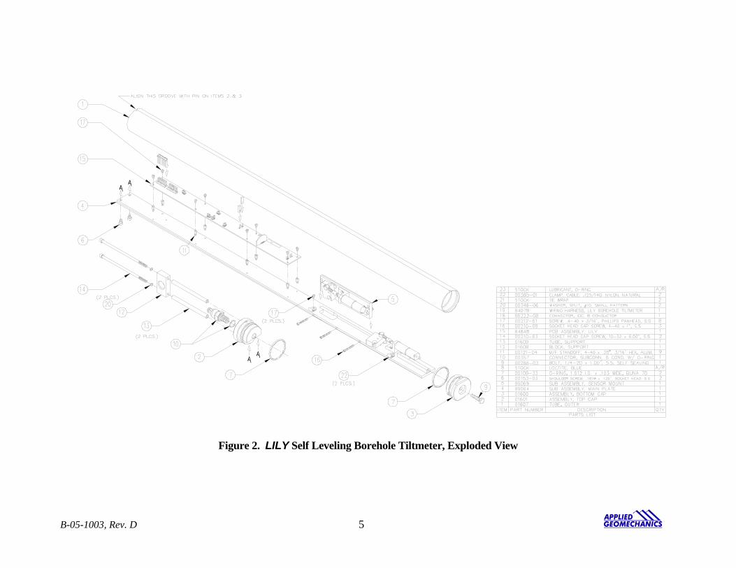
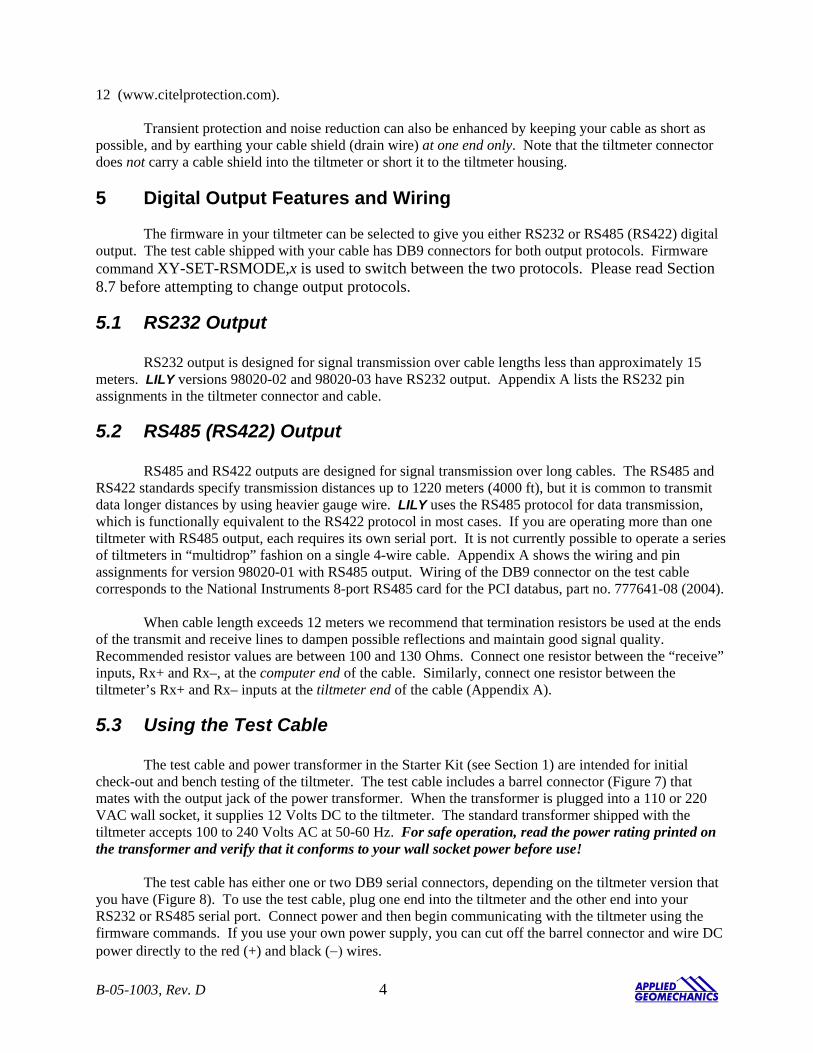
Figure 2. LILY Self Leveling Borehole Tiltmeter, Exploded View
B-05-1003, Rev. D 5

Figure 3. Assembled View, with and without Outer Tube
B-05-1003, Rev. D 6
03, Rev. D 7
Figure 4. Assembled View Showing Header Locations on Circuit Board
B-05-10
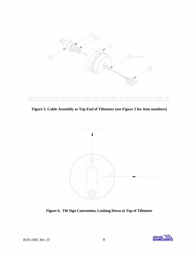
Figure 5. Cable Assembly at Top End of Tiltmeter (see Figure 2 for item numbers)
Figure 6. Tilt Sign Convention, Looking Down at Top of Tiltmeter
B-05-1003, Rev. D 8
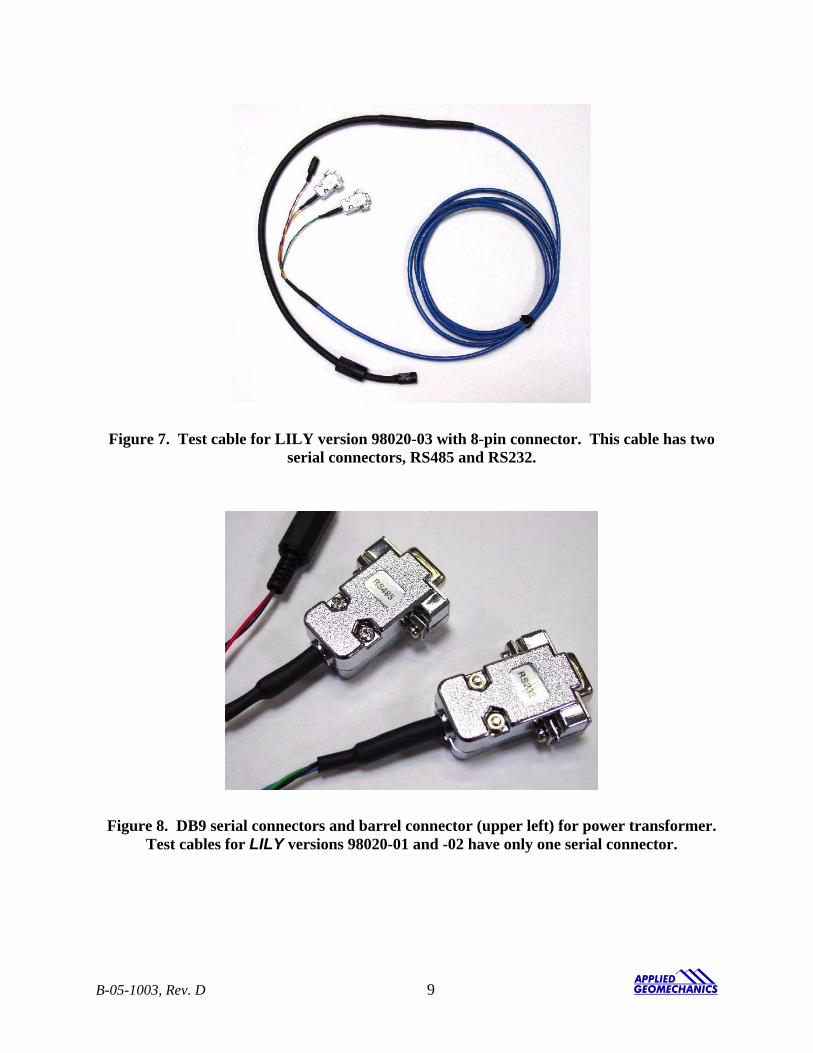
Figure 7. Test cable for LILY version 98020-03 with 8-pin connector. This cable has two serial connectors, RS485 and RS232.
Figure 8. DB9 serial connectors and barrel connector (upper left) for power transformer. Test cables for LILY versions 98020-01 and -02 have only one serial connector.
B-05-1003, Rev. D 9
6 Initial Check-Out Procedures Before installing your tiltmeter, verify that it is functioning properly by following the steps below. Refer to the firmware command summary in Section 8.3. The following instructions assume that the operator is using HyperTerminal (Windows 95 and later) to communicate with the tiltmeter:
1. Apply power and attach the tiltmeter to a PC according to the wire color and pin assignment code in Appendix A. Or, use the test cable (Figure 7 and 8) and power transformer supplied with your Starter Kit.
2. Open HyperTerminal, selecting the proper COM port and baud rate (the default baud rate for your
tiltmeter is 19200).
3. Type the command *9900XYC2 (note that the tiltmeter firmware commands are case sensitive).
4. If properly attached, the tiltmeter will now start outputting data through the serial port at a rate of 1 reading per second, and the data will be displayed in HyperTerminal.
5. Tilt the unit in the +X and then the +Y direction (Figure 6). Next tilt it in the –X and –Y
directions. Verify that the tilt values move through the full measurement range (Section 3) and that the sign (polarity) of the output changes on opposite sides of null.
6. Type the command *9900XYC-OFF to stop the output.
7. Your LILY tiltmeter is now ready for installation.
7 Installing and Leveling Your Tiltmeter, Collecting Data LILY tiltmeters are designed for installation at any depth in cased or uncased holes with internal diameters of 64 mm (2.5 inches) or greater. We consider an internal diameter of 76 mm (3 inches) to be ideal. If the diameter is too small, the tiltmeter may become stuck if the casing bends or deforms. To install your tiltmeter, first pour clean sand into bottom of the hole to a depth of 8-10 cm (3-4 inches). Lower LILY to the bottom of the hole on a rope which has been threaded through the hole in the handle (Figure 3). Then pour enough sand into the hole to cover the tiltmeter to the middle of the handle. Keep the rope on the tiltmeter if you plan to retrieve it later. After LILY has been installed in the hole, connect the cable to a computer, power the tiltmeter, and begin the self-leveling process by issuing the following firmware commands: *9900SO-SIM (This command puts the output into “Simple” format.) *9900XY-LEVEL,1 (This command begins the leveling process.)
The leveling process typically takes 5-10 minutes. When the X and Y readings are around 0 to +/-20 microradians, the leveling process will stop. You should then issue the following command before proceeding: *9900XY-LEVEL,0 (This command resets the tiltmeter so that it can be releveled again later.)
B-05-1003, Rev. D 10
Unless you plan to collect data with the “Simple” output format, you should now change the format using the SO command to your desired output format. For example, the following command changes the output to the XDR format. *9900SO-XDR Next, set the number of samples to average for each output. The command below sets the number at 8000: *9900XY-SET-N-SAMP,8000 To request a single sample, e.g., from a GPS receiver, issue the command: *9900XY Or, to continuously output once per minute, issue the command: *9900XYC4
Note that the LILY tiltmeter samples the waveform coming from each of the tilt sensors at a rate of 1 kilohertz. An 8000-sample average requires 8 seconds per sensor, or a total of 16 seconds to average enough samples for one output on each channel.
For a complete description of the firmware commands, see Section 8 and Appendix B.
7.1 Settling Behavior After you level the sensors in your tiltmeter, they will continue to “settle” until they reach equilibrium. A typical example of this settling is shown in Figure 9. In this example, the sensors were leveled after tiltmeter installation in a barrel filled with sand in the Applied Geomechanics laboratory. The graph (Figure 9) begins at the end of the leveling process and shows that the X sensor settled about 25 microradians and the Y sensor about 12 microradians over a period of a few hours (the increase in output at the end of the data set is caused by warming after sunrise). In some cases, we have found that leveling a second time after installation increases long-term stability and reduces long-term drift. 8 Communicating with your LILY Tiltmeter
8.1 Basic Requirements and Settings You may communicate with your tiltmeter using:
1. A terminal emulator program (e.g. Terminal in Windows 3.1 or HyperTerminal in Windows 95 and later); or
2. A GPS receiver that is capable of sending and receiving terminal commands.
All communication to the tiltmeter is performed through the send (transmit) and receive wires of the serial port. The default parameters for the serial port are set to no parity, 8 bits and 1 stop bit with no hardware or software flow control. The baud rate is the only parameter that is user-selectable. The default baud rate is 19200. Baud rates up to 115200 are supported.
B-05-1003, Rev. D 11
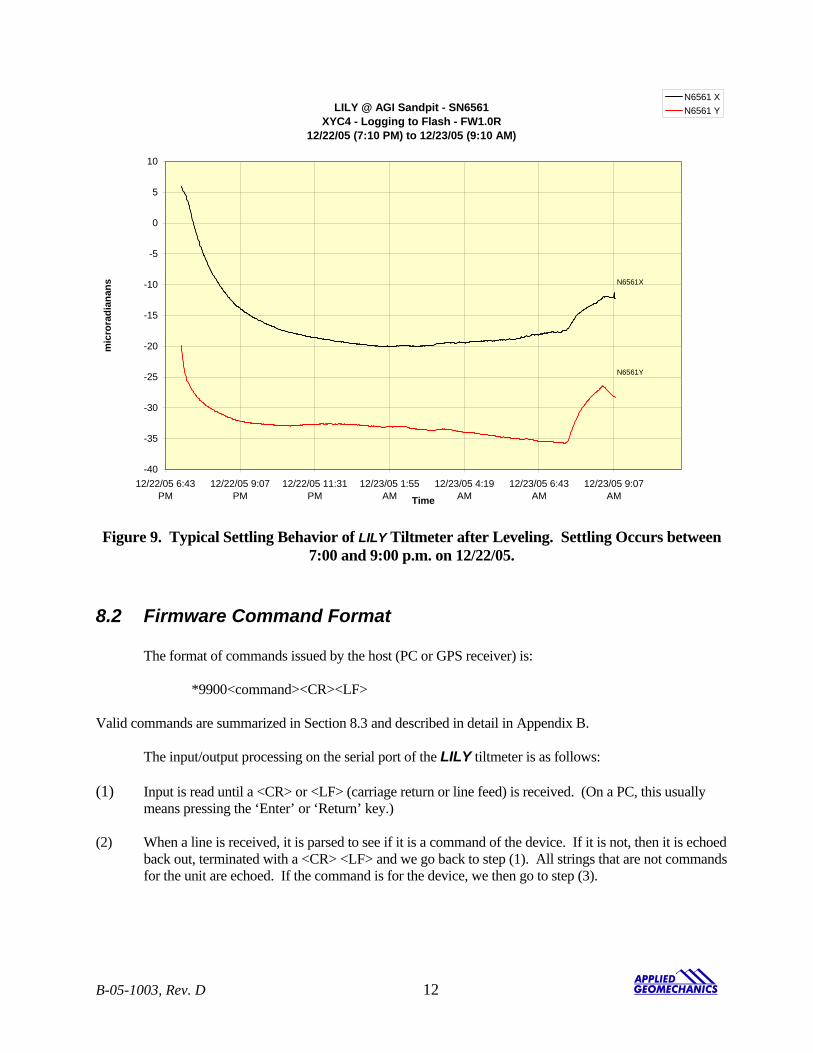
LILY @ AGI Sandpit - SN6561XYC4 - Logging to Flash - FW1.0R
12/22/05 (7:10 PM) to 12/23/05 (9:10 AM)
-40
-35
-30
-25
-20
-15
-10
-5
0
5
10
12/22/05 6:43PM
12/22/05 9:07PM
12/22/05 11:31PM
12/23/05 1:55AM
12/23/05 4:19AM
12/23/05 6:43AM
12/23/05 9:07AMTime
mic
rora
dian
ans
N6561 XN6561 Y
N6561X
N6561Y
Figure 9. Typical Settling Behavior of LILY Tiltmeter after Leveling. Settling Occurs between
7:00 and 9:00 p.m. on 12/22/05.
8.2 Firmware Command Format The format of commands issued by the host (PC or GPS receiver) is: *9900<command><CR><LF> Valid commands are summarized in Section 8.3 and described in detail in Appendix B. The input/output processing on the serial port of the LILY tiltmeter is as follows: (1) Input is read until a <CR> or <LF> (carriage return or line feed) is received. (On a PC, this usually
means pressing the ‘Enter’ or ‘Return’ key.) (2) When a line is received, it is parsed to see if it is a command of the device. If it is not, then it is echoed
back out, terminated with a <CR> <LF> and we go back to step (1). All strings that are not commands for the unit are echoed. If the command is for the device, we then go to step (3).
B-05-1003, Rev. D 12
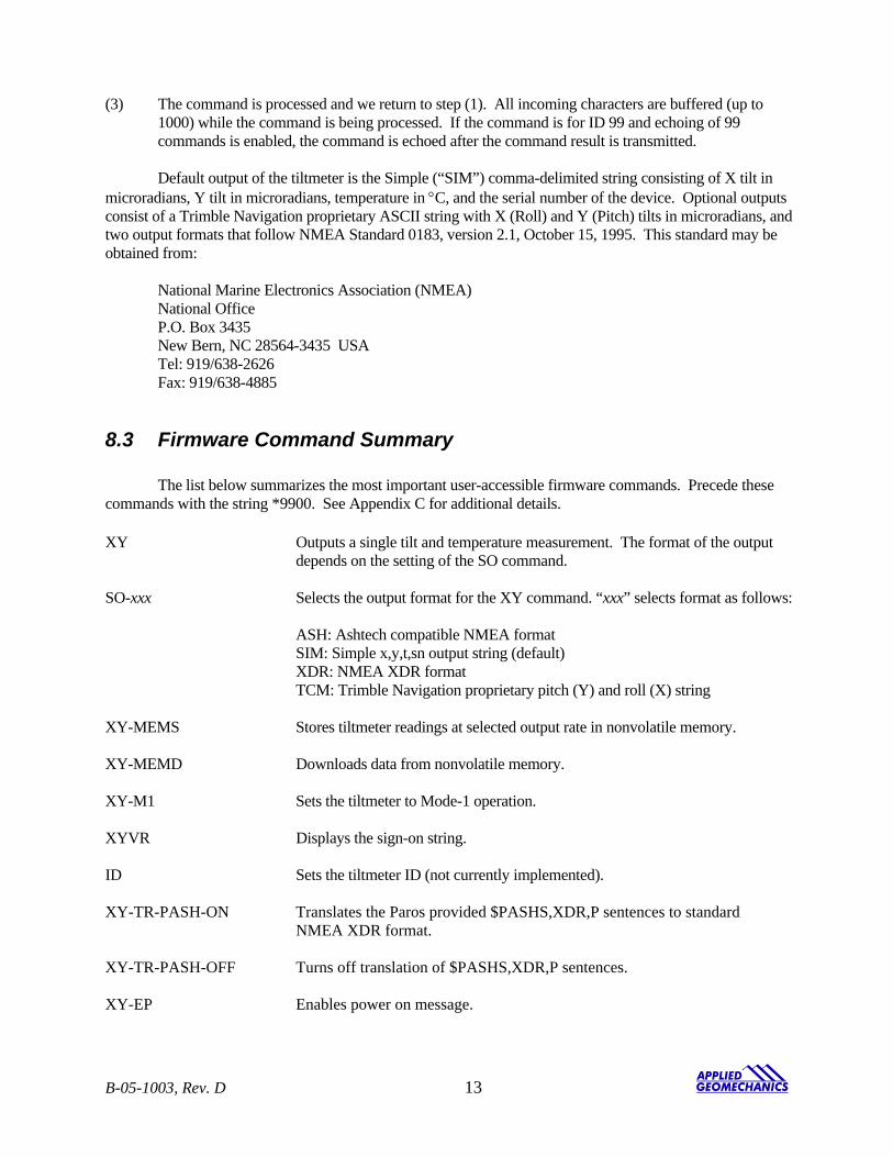
(3) The command is processed and we return to step (1). All incoming characters are buffered (up to 1000) while the command is being processed. If the command is for ID 99 and echoing of 99 commands is enabled, the command is echoed after the command result is transmitted.
Default output of the tiltmeter is the Simple (“SIM”) comma-delimited string consisting of X tilt in
microradians, Y tilt in microradians, temperature in °C, and the serial number of the device. Optional outputs consist of a Trimble Navigation proprietary ASCII string with X (Roll) and Y (Pitch) tilts in microradians, and two output formats that follow NMEA Standard 0183, version 2.1, October 15, 1995. This standard may be obtained from: National Marine Electronics Association (NMEA) National Office P.O. Box 3435 New Bern, NC 28564-3435 USA Tel: 919/638-2626 Fax: 919/638-4885
8.3 Firmware Command Summary
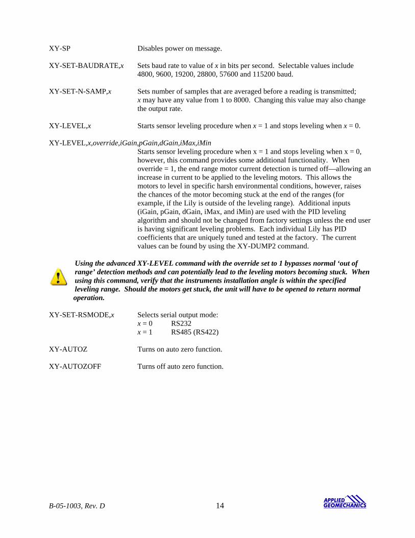
The list below summarizes the most important user-accessible firmware commands. Precede these commands with the string *9900. See Appendix C for additional details. XY Outputs a single tilt and temperature measurement. The format of the output
depends on the setting of the SO command. SO-xxx Selects the output format for the XY command. “xxx” selects format as follows:
ASH: Ashtech compatible NMEA format SIM: Simple x,y,t,sn output string (default) XDR: NMEA XDR format TCM: Trimble Navigation proprietary pitch (Y) and roll (X) string
XY-MEMS Stores tiltmeter readings at selected output rate in nonvolatile memory. XY-MEMD Downloads data from nonvolatile memory. XY-M1 Sets the tiltmeter to Mode-1 operation. XYVR Displays the sign-on string. ID Sets the tiltmeter ID (not currently implemented). XY-TR-PASH-ON Translates the Paros provided $PASHS,XDR,P sentences to standard NMEA XDR format. XY-TR-PASH-OFF Turns off translation of $PASHS,XDR,P sentences. XY-EP Enables power on message.
B-05-1003, Rev. D 13
XY-SP Disables power on message. XY-SET-BAUDRATE,x Sets baud rate to value of x in bits per second. Selectable values include
4800, 9600, 19200, 28800, 57600 and 115200 baud. XY-SET-N-SAMP,x Sets number of samples that are averaged before a reading is transmitted; x may have any value from 1 to 8000. Changing this value may also change
the output rate. XY-LEVEL,x Starts sensor leveling procedure when x = 1 and stops leveling when x = 0. XY-LEVEL,x,override,iGain,pGain,dGain,iMax,iMin Starts sensor leveling procedure when x = 1 and stops leveling when x = 0,
however, this command provides some additional functionality. When override = 1, the end range motor current detection is turned off—allowing an increase in current to be applied to the leveling motors. This allows the motors to level in specific harsh environmental conditions, however, raises the chances of the motor becoming stuck at the end of the ranges (for example, if the Lily is outside of the leveling range). Additional inputs (iGain, pGain, dGain, iMax, and iMin) are used with the PID leveling algorithm and should not be changed from factory settings unless the end user is having significant leveling problems. Each individual Lily has PID coefficients that are uniquely tuned and tested at the factory. The current values can be found by using the XY-DUMP2 command.
Using the advanced XY-LEVEL command with the override set to 1 bypasses normal ‘out of range’ detection methods and can potentially lead to the leveling motors becoming stuck. When using this command, verify that the instruments installation angle is within the specified leveling range. Should the motors get stuck, the unit will have to be opened to return normal operation.
XY-SET-RSMODE,x Selects serial output mode: x = 0 RS232 x = 1 RS485 (RS422) XY-AUTOZ Turns on auto zero function. XY-AUTOZOFF Turns off auto zero function.
B-05-1003, Rev. D 14
XYCx Continuously sends XY data where x determines output rate as follows:
x = 0: 8-10 outputs per second x = 1: 4 outputs per second x = 2: 1 output per second (default) x = 3: 1 output every 10 seconds x = 4: 1 output every 60 seconds x = 5: 1 output every hour x = 6: 1 output every 12 hours x = 7: 1 output every 24 hours x = 0A: Averaging of the 8-10 outputs per second data x = 1A: Averaging of the 4 outputs per second data x = 2A or x = A: Averaging of the 1 output per second data
Once initiated, continuous output remains in effect until turned off with the XYC-OFF command (see below).
XYC-OFF Turns off XYC mode. XY-SET-MAG,x Adds compass heading to Simple (SIM) output string when x = 1 and
removes it when x = 0. This command works only when the tiltmeter output is set to the Simple (SIM) output string (see section 8.4).
XY- MAG-OFFSET,x Sets the magnetic declination. The x value is added to the measured output. XY-DUMP-SETTINGS Dumps settings of device. XY-DUMP2 Dumps extended settings of device. XY-TOGGLE-SUPPLYVOLTAGE Appends a supply voltage reading to the Simple (SIM) output string when toggled on (see section 8.4). XY-TOGGLE-TIMESTAMP Appends a timestamp to the Simple (SIM) output string when
toggled on (see section 8.4). SET-TIME,sec,min,hour,day,month,year Sets the current Lily time to a specific time. Each input must
be two characters long: sec 00-59 min 00-59 hour 00-23 day 00-31 month 00-12 year 00-99
B-05-1003, Rev. D 15
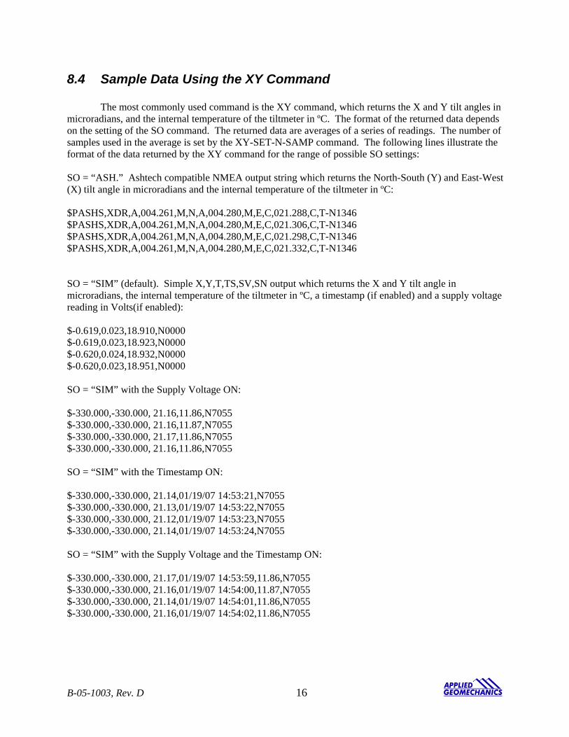
8.4 Sample Data Using the XY Command The most commonly used command is the XY command, which returns the X and Y tilt angles in microradians, and the internal temperature of the tiltmeter in ºC. The format of the returned data depends on the setting of the SO command. The returned data are averages of a series of readings. The number of samples used in the average is set by the XY-SET-N-SAMP command. The following lines illustrate the format of the data returned by the XY command for the range of possible SO settings: SO = “ASH.” Ashtech compatible NMEA output string which returns the North-South (Y) and East-West (X) tilt angle in microradians and the internal temperature of the tiltmeter in ºC: $PASHS,XDR,A,004.261,M,N,A,004.280,M,E,C,021.288,C,T-N1346 $PASHS,XDR,A,004.261,M,N,A,004.280,M,E,C,021.306,C,T-N1346 $PASHS,XDR,A,004.261,M,N,A,004.280,M,E,C,021.298,C,T-N1346 $PASHS,XDR,A,004.261,M,N,A,004.280,M,E,C,021.332,C,T-N1346 SO = “SIM” (default). Simple X,Y,T,TS,SV,SN output which returns the X and Y tilt angle in microradians, the internal temperature of the tiltmeter in ºC, a timestamp (if enabled) and a supply voltage reading in Volts(if enabled): $-0.619,0.023,18.910,N0000 $-0.619,0.023,18.923,N0000 $-0.620,0.024,18.932,N0000 $-0.620,0.023,18.951,N0000 SO = “SIM” with the Supply Voltage ON: $-330.000,-330.000, 21.16,11.86,N7055 $-330.000,-330.000, 21.16,11.87,N7055 $-330.000,-330.000, 21.17,11.86,N7055 $-330.000,-330.000, 21.16,11.86,N7055 SO = “SIM” with the Timestamp ON: $-330.000,-330.000, 21.14,01/19/07 14:53:21,N7055 $-330.000,-330.000, 21.13,01/19/07 14:53:22,N7055 $-330.000,-330.000, 21.12,01/19/07 14:53:23,N7055 $-330.000,-330.000, 21.14,01/19/07 14:53:24,N7055 SO = “SIM” with the Supply Voltage and the Timestamp ON: $-330.000,-330.000, 21.17,01/19/07 14:53:59,11.86,N7055 $-330.000,-330.000, 21.16,01/19/07 14:54:00,11.87,N7055 $-330.000,-330.000, 21.14,01/19/07 14:54:01,11.86,N7055 $-330.000,-330.000, 21.16,01/19/07 14:54:02,11.86,N7055
B-05-1003, Rev. D 16
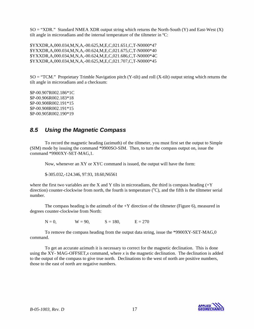
SO = “XDR.” Standard NMEA XDR output string which returns the North-South (Y) and East-West (X) tilt angle in microradians and the internal temperature of the tiltmeter in ºC: $YXXDR,A,000.034,M,N,A,-00.625,M,E,C,021.651,C,T-N0000*47 $YXXDR,A,000.034,M,N,A,-00.624,M,E,C,021.675,C,T-N0000*40 $YXXDR,A,000.034,M,N,A,-00.624,M,E,C,021.686,C,T-N0000*4C $YXXDR,A,000.034,M,N,A,-00.625,M,E,C,021.707,C,T-N0000*45 SO = “TCM.” Proprietary Trimble Navigation pitch (Y-tilt) and roll (X-tilt) output string which returns the tilt angle in microradians and a checksum: $P-00.907R002.186*1C $P-00.906R002.183*18 $P-00.908R002.191*15 $P-00.908R002.191*15 $P-00.905R002.190*19
8.5 Using the Magnetic Compass To record the magnetic heading (azimuth) of the tiltmeter, you must first set the output to Simple (SIM) mode by issuing the command *9900SO-SIM. Then, to turn the compass output on, issue the command *9900XY-SET-MAG,1.
Now, whenever an XY or XYC command is issued, the output will have the form: $-305.032,-124.346, 97.93, 18.60,N6561 where the first two variables are the X and Y tilts in microradians, the third is compass heading (+Y direction) counter-clockwise from north, the fourth is temperature (oC), and the fifth is the tiltmeter serial number. The compass heading is the azimuth of the +Y direction of the tiltmeter (Figure 6), measured in degrees counter-clockwise from North: N = 0, W = 90, S = 180, E = 270 To remove the compass heading from the output data string, issue the *9900XY-SET-MAG,0 command.
To get an accurate azimuth it is necessary to correct for the magnetic declination. This is done using the XY- MAG-OFFSET,x command, where x is the magnetic declination. The declination is added to the output of the compass to give true north. Declinations to the west of north are positive numbers, those to the east of north are negative numbers.
B-05-1003, Rev. D 17
8.6 Recording Data in Internal Memory or on a PC; Data File Sizes
You can log data to nonvolatile FLASH memory in your LILY tiltmeter by using the XY-MEMS command. Data stored to FLASH memory must be stored in simple (SIM) format. Storage capacity is 2 megabytes, or approximately 64,000 lines of data. To download the data to a PC or other device, issue the XY-MEMD command.
If you record the data to a PC, the sizes of the data files are approximately: Format ASH 16.5 lines = 1 kilobyte SIM 29.8 lines = 1 kilobyte XDR 16.6 lines = 1 kilobyte TCM 42.3 lines = 1 kilobyte
8.7 Switching between RS232 and RS485 Output
If you have the LILY version with the 8-pin connector (part no. 98020-03) you may switch the output between RS232 and RS485 by issuing the *9900XY-SET-RSMODE firmware command. However, after switching to RS485, an RS232 port can no longer be used to communicate with the tiltmeter. You must switch to the RS485 serial connector on the test cable (Figure 8) and an RS485 port on your computer. Similarly, after a switch to RS232, the RS485 serial connector and port can no longer be used.
If your LILY has a 6-pin connector, it is wired for only one output protocol, RS485 or RS232. Do not switch output protocols. If this happens, you will lose the ability to communicate with your tiltmeter!
9 Maintenance and Troubleshooting LILY tiltmeters are rugged and require no special maintenance other than normal care and cleaning. Apart from the procedures described below, the tiltmeters are not field-serviceable. If you encounter problems not described here, please contact Applied Geomechanics Inc. at (831) 462-2801 or [email protected] in California. A service engineer will assist you in determining the cause of any problem.
9.1 Routine Maintenance Keep all tiltmeters away from extremes of heat and cold. Extreme temperatures shorten the life of the seals and unnecessarily stress the electronic components. Keep tiltmeters out of direct sun because the internal temperature can reach levels much greater than the ambient temperature. We advise keeping a light coating of silicone grease on the rubber of the connector to prevent it from drying and cracking at times when it is not submerged.
B-05-1003, Rev. D 18
9.2 Determining the Cause of Malfunctions Although your tiltmeter is not field-serviceable, there are some basic things you can do if you encounter problems. If there is no output when you have connected the tiltmeter to a PC while using HyperTerminal, check that all connectors are securely attached and properly wired to the power and communication pins. Failure to obtain an output signal from the tiltmeter normally is the result of lack of power or a broken wire or connection. If no communication is seen in HyperTerminal, check your port settings. Most computers connect to their serial ports using COM 1-4. Verify that the software settings conform to the COM port that you are using. The default baud rate of the tiltmeter is 19200 baud, which is factory set and verified upon shipment. If your computer requires a different baud rate, change the tiltmeter’s baud rate setting using the XY-SET-BAUDRATE command. Check your wiring (Appendix A), as RS485(RS422) uses different signals and connector pins than the single-ended RS232 protocol. For either protocol, verify that the tiltmeter’s transmit output is connected to the receive pin(s) on the computer and that its receive is connected to the PC’s transmit pin(s). If the tiltmeter output is “pegged” at either end of the output range, the tiltmeter is probably tilted off scale. Relevel the unit.
9.3 Opening Your LILY Tiltmeter
If you suspect a hardware problem inside the tiltmeter, it may be opened for inspection, as follows:
1. Unscrew the ¼-20 bolt in the center of the bottom cap (item 9 in Figure 2). 2. Slide the outer tube downward (away from the top cap), taking care to not damage any of the
internal components in the process.
After the outer tube has been removed, inspect the internal assembly for loose connectors or other problems. If a connector appears to be loose, push it back onto its mating header pins.
To reassemble the tiltmeter, reverse the process above. Make sure that all 0-rings and their contact surfaces, including the O-ring on the ¼-20 bolt, are clean and have no cuts or scratches. They should receive a light coating of silicone grease before reassembling the tiltmeter. WARNING! NEVER USE AN OHMMETER TO MEASURE THE TILT SENSORS INSIDE THE TILTMETER. APPLYING DC CURRENT THROUGH THE SENSORS WILL CAUSE
PERMANENT DAMAGE THAT IS NOT COVERED BY THE WARRANTY!
B-05-1003, Rev. D 19
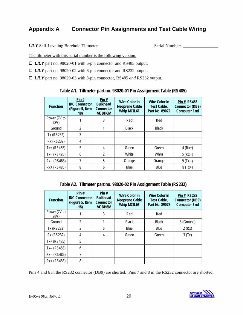
Appendix A Connector Pin Assignments and Test Cable Wiring LILY Self-Leveling Borehole Tiltmeter Serial Number: ________________
The tiltmeter with this serial number is the following version:
LILY part no. 98020-01 with 6-pin connector and RS485 output.
LILY part no. 98020-02 with 6-pin connector and RS232 output.
LILY part no. 98020-03 with 8-pin connector, RS485 and RS232 output.
Table A1. Tiltmeter part no. 98020-01 Pin Assignment Table (RS485)
Function Pin #
IDC Connector (Figure 5, Item
18)
Pin # Bulkhead Connector MCBH6M
Wire Color in Neoprene Cable
Whip MCIL6F
Wire Color in Test Cable,
Part No. 89072
Pin # RS485 Connector (DB9) Computer End
Power (7V to 28V) 1 3 Red Red
Ground 2 1 Black Black Tx (RS232) 3 Rx (RS232) 4 Tx+ (RS485) 5 4 Green Green 4 (Rx+) Tx− (RS485) 6 2 White White 5 (Rx−) Rx− (RS485) 7 5 Orange Orange 9 (Tx−) Rx+ (RS485) 8 6 Blue Blue 8 (Tx+)
Table A2. Tiltmeter part no. 98020-02 Pin Assignment Table (RS232)
Function Pin #
IDC Connector (Figure 5, Item
18)
Pin # Bulkhead Connector MCBH6M
Wire Color in Neoprene Cable
Whip MCIL6F
Wire Color in Test Cable,
Part No. 89078
Pin # RS232 Connector (DB9) Computer End
Power (7V to 28V) 1 3 Red Red
Ground 2 1 Black Black 5 (Ground) Tx (RS232) 3 6 Blue Blue 2 (Rx) Rx (RS232) 4 4 Green Green 3 (Tx) Tx+ (RS485) 5 Tx− (RS485) 6 Rx− (RS485) 7 Rx+ (RS485) 8
Pins 4 and 6 in the RS232 connector (DB9) are shorted. Pins 7 and 8 in the RS232 connector are shorted.
B-05-1003, Rev. D 20
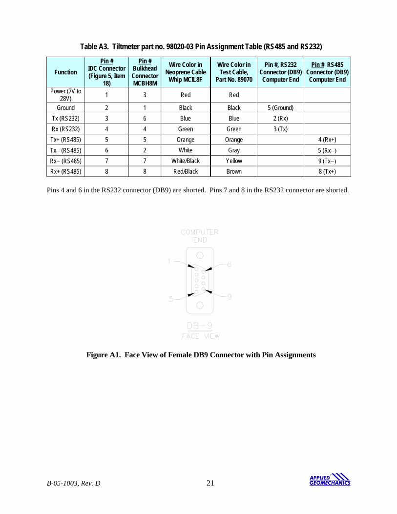
Table A3. Tiltmeter part no. 98020-03 Pin Assignment Table (RS485 and RS232)
Function Pin #
IDC Connector (Figure 5, Item
18)
Pin # Bulkhead Connector MCBH8M
Wire Color in Neoprene Cable
Whip MCIL8F
Wire Color in Test Cable,
Part No. 89070
Pin #, RS232 Connector (DB9) Computer End
Pin # RS485 Connector (DB9) Computer End
Power (7V to 28V) 1 3 Red Red
Ground 2 1 Black Black 5 (Ground) Tx (RS232) 3 6 Blue Blue 2 (Rx) Rx (RS232) 4 4 Green Green 3 (Tx) Tx+ (RS485) 5 5 Orange Orange 4 (Rx+) Tx− (RS485) 6 2 White Gray 5 (Rx−) Rx− (RS485) 7 7 White/Black Yellow 9 (Tx−) Rx+ (RS485) 8 8 Red/Black Brown 8 (Tx+)
Pins 4 and 6 in the RS232 connector (DB9) are shorted. Pins 7 and 8 in the RS232 connector are shorted.
Figure A1. Face View of Female DB9 Connector with Pin Assignments
B-05-1003, Rev. D 21
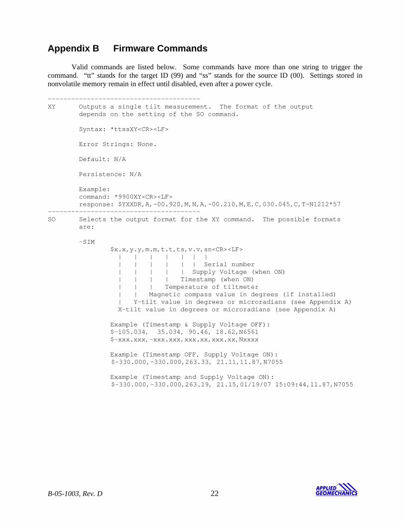
Appendix B Firmware Commands Valid commands are listed below. Some commands have more than one string to trigger the command. “tt” stands for the target ID (99) and “ss” stands for the source ID (00). Settings stored in nonvolatile memory remain in effect until disabled, even after a power cycle. --------------------------------------- XY Outputs a single tilt measurement. The format of the output depends on the setting of the SO command. Syntax: *ttssXY<CR><LF> Error Strings: None. Default: N/A Persistence: N/A Example: command: *9900XY<CR><LF> response: $YXXDR,A,-00.920,M,N,A,-00.210,M,E,C,030.045,C,T-N1212*57 --------------------------------------- SO Selects the output format for the XY command. The possible formats are: -SIM $x.x,y.y,m.m,t.t,ts,v.v,sn<CR><LF> | | | | | | | | | | | | | Serial number | | | | | Supply Voltage (when ON) | | | | Timestamp (when ON) | | | Temperature of tiltmeter | | Magnetic compass value in degrees (if installed) | Y-tilt value in degrees or microradians (see Appendix A) X-tilt value in degrees or microradians (see Appendix A) Example (Timestamp & Supply Voltage OFF): $-105.034, 35.034, 90.46, 18.62,N6561 $-xxx.xxx,-xxx.xxx,xxx.xx,xxx.xx,Nxxxx Example (Timestamp OFF, Supply Voltage ON): $-330.000,-330.000,263.33, 21.11,11.87,N7055 Example (Timestamp and Supply Voltage ON): $-330.000,-330.000,263.19, 21.15,01/19/07 15:09:44,11.87,N7055
B-05-1003, Rev. D 22
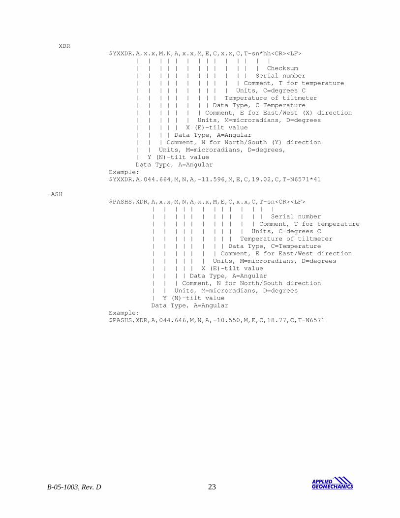
-XDR $YXXDR,A,x.x,M,N,A,x.x,M,E,C,x.x,C,T-sn*hh<CR><LF> | | | | | | | | | | | | | | | | | | | | | | | | | | | Checksum | | | | | | | | | | | | Serial number | | | | | | | | | | | Comment, T for temperature | | | | | | | | | | Units, C=degrees C | | | | | | | | | Temperature of tiltmeter | | | | | | | | Data Type, C=Temperature | | | | | | | Comment, E for East/West (X) direction | | | | | | Units, M=microradians, D=degrees | | | | | X (E)-tilt value | | | | Data Type, A=Angular | | | Comment, N for North/South (Y) direction | | Units, M=microradians, D=degrees, | Y (N)-tilt value Data Type, A=Angular Example: $YXXDR,A,044.664,M,N,A,-11.596,M,E,C,19.02,C,T-N6571*41 -ASH $PASHS,XDR,A,x.x,M,N,A,x.x,M,E,C,x.x,C,T-sn<CR><LF> | | | | | | | | | | | | | | | | | | | | | | | | | Serial number | | | | | | | | | | | Comment, T for temperature | | | | | | | | | | Units, C=degrees C | | | | | | | | | Temperature of tiltmeter | | | | | | | | Data Type, C=Temperature | | | | | | | Comment, E for East/West direction | | | | | | Units, M=microradians, D=degrees | | | | | X (E)-tilt value | | | | Data Type, A=Angular | | | Comment, N for North/South direction | | Units, M=microradians, D=degrees | Y (N)-tilt value Data Type, A=Angular Example: $PASHS,XDR,A,044.646,M,N,A,-10.550,M,E,C,18.77,C,T-N6571
B-05-1003, Rev. D 23
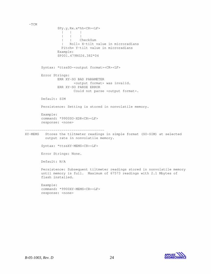
-TCM $Py.y,Rx.x*hh<CR><LF> | | | | | | | | CheckSum | Roll= X-tilt value in microradians Pitch= Y-tilt value in microradians Example: $P001.479R026.382*04 Syntax: *ttssSO-<output format><CR><LF> Error Strings: ERR XY-SO BAD PARAMETER <output format> was invalid. ERR XY-SO PARSE ERROR Could not parse <output format>. Default: SIM Persistence: Setting is stored in nonvolatile memory. Example: command: *9900SO-XDR<CR><LF> response: <none> --------------------------------------- XY-MEMS Stores the tiltmeter readings in simple format (SO-SIM) at selected output rate in nonvolatile memory. Syntax: *ttssXY-MEMS<CR><LF> Error Strings: None. Default: N/A Persistence: Subsequent tiltmeter readings stored in nonvolatile memory until memory is full. Maximum of 67573 readings with 2.1 Mbytes of flash installed. Example: command: *9900XY-MEMS<CR><LF> response: <none>
B-05-1003, Rev. D 24
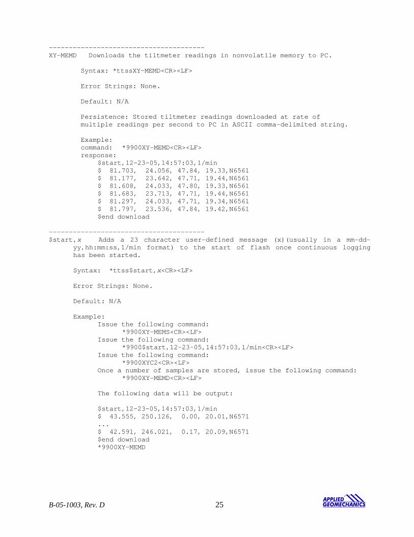
--------------------------------------- XY-MEMD Downloads the tiltmeter readings in nonvolatile memory to PC. Syntax: *ttssXY-MEMD<CR><LF> Error Strings: None. Default: N/A Persistence: Stored tiltmeter readings downloaded at rate of multiple readings per second to PC in ASCII comma-delimited string. Example: command: *9900XY-MEMD<CR><LF> response:
$start,12-23-05,14:57:03,1/min $ 81.703, 24.056, 47.84, 19.33,N6561 $ 81.177, 23.642, 47.71, 19.44,N6561 $ 81.608, 24.033, 47.80, 19.33,N6561 $ 81.683, 23.713, 47.71, 19.44,N6561 $ 81.297, 24.033, 47.71, 19.34,N6561 $ 81.797, 23.536, 47.84, 19.42,N6561 $end download
--------------------------------------- $start ,x Adds a 23 character user-defined message (x)(usually in a mm-dd-
yy,hh:mm:ss,1/min format) to the start of flash once continuous logging has been started.
Syntax: *ttss$start,x<CR><LF>
Error Strings: None. Default: N/A Example:
Issue the following command: *9900XY-MEMS<CR><LF>
Issue the following command: *9900$start,12-23-05,14:57:03,1/min<CR><LF>
Issue the following command: *9900XYC2<CR><LF>
Once a number of samples are stored, issue the following command: *9900XY-MEMD<CR><LF> The following data will be output: $start,12-23-05,14:57:03,1/min $ 43.555, 250.126, 0.00, 20.01,N6571 ... $ 42.591, 246.021, 0.17, 20.09,N6571 $end download *9900XY-MEMD
B-05-1003, Rev. D 25
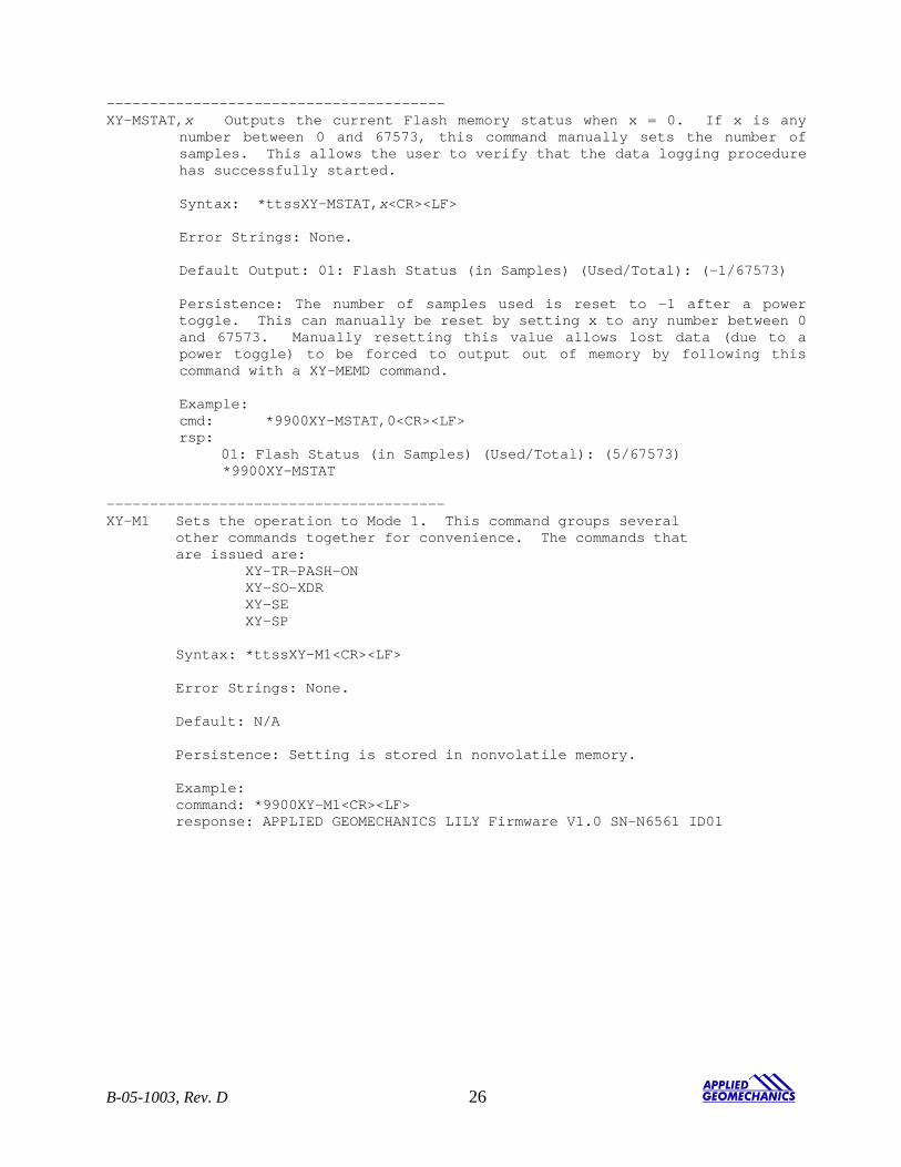
--------------------------------------- XY-MSTAT,x Outputs the current Flash memory status when x = 0. If x is any
number between 0 and 67573, this command manually sets the number of samples. This allows the user to verify that the data logging procedure has successfully started.
Syntax: *ttssXY-MSTAT,x<CR><LF> Error Strings: None. Default Output: 01: Flash Status (in Samples) (Used/Total): (-1/67573)
Persistence: The number of samples used is reset to -1 after a power toggle. This can manually be reset by setting x to any number between 0 and 67573. Manually resetting this value allows lost data (due to a power toggle) to be forced to output out of memory by following this command with a XY-MEMD command. Example: cmd: *9900XY-MSTAT,0<CR><LF> rsp: 01: Flash Status (in Samples) (Used/Total): (5/67573) *9900XY-MSTAT
--------------------------------------- XY-M1 Sets the operation to Mode 1. This command groups several other commands together for convenience. The commands that are issued are: XY-TR-PASH-ON XY-SO-XDR XY-SE XY-SP Syntax: *ttssXY-M1<CR><LF> Error Strings: None. Default: N/A Persistence: Setting is stored in nonvolatile memory. Example: command: *9900XY-M1<CR><LF> response: APPLIED GEOMECHANICS LILY Firmware V1.0 SN-N6561 ID01
B-05-1003, Rev. D 26
--------------------------------------- XYVR Displays the sign-on string. Syntax: *ttssXYVR<CR><LF> Error Strings: None. Default: N/A Persistence: N/A Example: command: *9900XYVR<CR><LF> response: APPLIED GEOMECHANICS LILY Firmware V1.0 SN-N6561 ID01 --------------------------------------- ID This command is not currently supported. Sets the ID of units in the daisy chain. The first device in the serial chain sets its ID to the source ID plus one (ss+1), and then outputs a the ID command to the next device with the source ID set to its new ID. The target ID of this command must be 99. Syntax: *99ssID<CR><LF> Error Strings: None. Default: 01 Persistence: Setting is stored in nonvolatile memory. Example: command: *9900ID<CR><LF> response: *9901ID<CR><LF> --------------------------------------- XY-TR-PASH-ON Translates the Paros provided $PASHS,XDR,P sentences to standard NMEA XDR format. An example input PASH string would be: $PASHS,XDR,P,1.000123,B,SN123,C,22.12,C,SN123,H,32.11,P,SN123<CR><LF> The translated string would then be: $WIXDR,P,1.000123,B,SN123,C,22.12,C,SN123,H,32.11,P,SN123*hh<CR><LF> Syntax: *ttssXY-TR-PASH-ON<CR><LF> Error Strings: None. Default: Off. Persistence: Setting is stored in nonvolatile memory. Example: command: *9900XY-TR-PASH-ON<CR><LF> response: <none>
B-05-1003, Rev. D 27
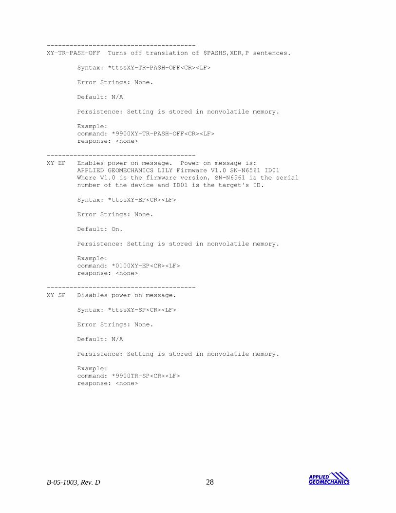
--------------------------------------- XY-TR-PASH-OFF Turns off translation of $PASHS,XDR,P sentences. Syntax: *ttssXY-TR-PASH-OFF<CR><LF> Error Strings: None. Default: N/A Persistence: Setting is stored in nonvolatile memory. Example: command: *9900XY-TR-PASH-OFF<CR><LF> response: <none> --------------------------------------- XY-EP Enables power on message. Power on message is: APPLIED GEOMECHANICS LILY Firmware V1.0 SN-N6561 ID01 Where V1.0 is the firmware version, SN-N6561 is the serial number of the device and ID01 is the target's ID. Syntax: *ttssXY-EP<CR><LF> Error Strings: None. Default: On. Persistence: Setting is stored in nonvolatile memory. Example: command: *0100XY-EP<CR><LF> response: <none> --------------------------------------- XY-SP Disables power on message. Syntax: *ttssXY-SP<CR><LF> Error Strings: None. Default: N/A Persistence: Setting is stored in nonvolatile memory. Example: command: *9900TR-SP<CR><LF> response: <none>
B-05-1003, Rev. D 28
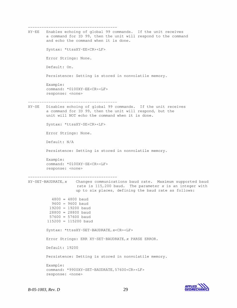
--------------------------------------- XY-EE Enables echoing of global 99 commands. If the unit receives a command for ID 99, then the unit will respond to the command and echo the command when it is done. Syntax: *ttssXY-EE<CR><LF> Error Strings: None. Default: On. Persistence: Setting is stored in nonvolatile memory. Example: command: *0100XY-EE<CR><LF> response: <none> --------------------------------------- XY-SE Disables echoing of global 99 commands. If the unit receives a command for ID 99, then the unit will respond, but the unit will NOT echo the command when it is done. Syntax: *ttssXY-SE<CR><LF> Error Strings: None. Default: N/A Persistence: Setting is stored in nonvolatile memory. Example: command: *0100XY-SE<CR><LF> response: <none> --------------------------------------- XY-SET-BAUDRATE,x Changes communications baud rate. Maximum supported baud rate is 115,200 baud. The parameter x is an integer with up to six places, defining the baud rate as follows:
4800 = 4800 baud 9600 = 9600 baud 19200 = 19200 baud 28800 = 28800 baud 57600 = 57600 baud 115200 = 115200 baud
Syntax: *ttssXY-SET-BAUDRATE,x<CR><LF> Error Strings: ERR XY-SET-BAUDRATE,x PARSE ERROR. Default: 19200 Persistence: Setting is stored in nonvolatile memory. Example: command: *9900XY-SET-BAUDRATE,57600<CR><LF> response: <none>
B-05-1003, Rev. D 29
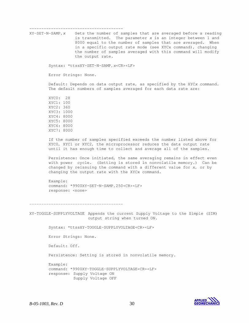
--------------------------------------- XY-SET-N-SAMP,x Sets the number of samples that are averaged before a reading is transmitted. The parameter x is an integer between 1 and 8000 equal to the number of samples that are averaged. When in a specific output rate mode (see XYCx command), changing the number of samples averaged with this command will modify the output rate. Syntax: *ttssXY-SET-N-SAMP,x<CR><LF> Error Strings: None. Default: Depends on data output rate, as specified by the XYCx command. The default numbers of samples averaged for each data rate are: XYC0: 28 XYC1: 100 XYC2: 360 XYC3: 1000 XYC4: 8000 XYC5: 8000 XYC6: 8000 XYC7: 8000 If the number of samples specified exceeds the number listed above for XYC0, XYC1 or XYC2, the microprocessor reduces the data output rate until it has enough time to collect and average all of the samples. Persistence: Once initiated, the same averaging remains in effect even with power cycle. (Setting is stored in nonvolatile memory.) Can be changed by reissuing the command with a different value for x, or by changing the output rate with the XYCx command. Example: command: *9900XY-SET-N-SAMP,250<CR><LF> response: <none> --------------------------------------- XY-TOGGLE-SUPPLYVOLTAGE Appends the current Supply Voltage to the Simple (SIM) output string when turned ON. Syntax: *ttssXY-TOGGLE-SUPPLYVOLTAGE<CR><LF> Error Strings: None. Default: Off. Persistence: Setting is stored in nonvolatile memory. Example: command: *9900XY-TOGGLE-SUPPLYVOLTAGE<CR><LF> response: Supply Voltage ON Supply Voltage OFF
B-05-1003, Rev. D 30
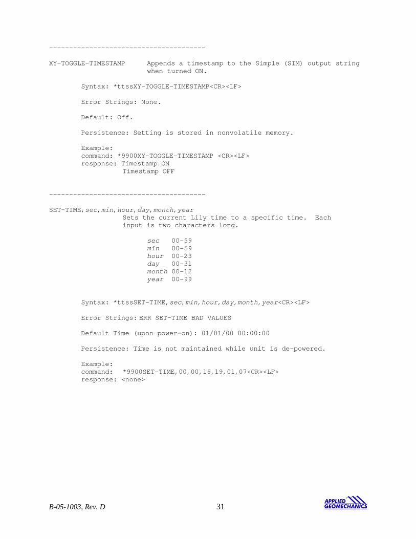
--------------------------------------- XY-TOGGLE-TIMESTAMP Appends a timestamp to the Simple (SIM) output string when turned ON. Syntax: *ttssXY-TOGGLE-TIMESTAMP<CR><LF> Error Strings: None. Default: Off. Persistence: Setting is stored in nonvolatile memory. Example: command: *9900XY-TOGGLE-TIMESTAMP <CR><LF> response: Timestamp ON Timestamp OFF --------------------------------------- SET-TIME,sec,min,hour,day,month,year
Sets the current Lily time to a specific time. Each input is two characters long.
sec 00-59 min 00-59 hour 00-23 day 00-31 month 00-12 year 00-99 Syntax: *ttssSET-TIME,sec,min,hour,day,month,year<CR><LF> Error Strings: ERR SET-TIME BAD VALUES Default Time (upon power-on): 01/01/00 00:00:00 Persistence: Time is not maintained while unit is de-powered. Example: command: *9900SET-TIME,00,00,16,19,01,07<CR><LF> response: <none>
B-05-1003, Rev. D 31
--------------------------------------- XY-SET-RSMODE,x Sets output protocol to RS232 or RS485(RS422), as follows: x = 0: RS232 x = 1: RS485(RS422) Syntax: *ttss XY-SET-RSMODE,x<CR><LF> Error Strings: None. Default: Set in factory to customer specification. Persistence: Once initiated, remains in effect even with power cycle. (Setting is stored in nonvolatile memory.) Example: command: *9900XY-SET-RSMODE,0<CR><LF> response: <none> CAUTION: If you change the output protocol, you will no longer be able to communicate with the tiltmeter unless you have the correct interconnect cable and serial port. --------------------------------------- XY-AUTOZ Turns autozero function on, causing tiltmeter to subtract current X and Y readings from all subsequent X and Y readings. Syntax: *ttssXY-AUTOZ <CR><LF> Error Strings: None. Default: Off. Persistence: Setting is stored in nonvolatile memory. Example: command: *9900XY-AUTOZ<CR><LF> response: <none> --------------------------------------- XY-AUTOZOFF Turns autozero function off, causing tiltmeter to display non-biased (unshifted) position readings. Syntax: *ttssXY-AUTOZ-OFF<CR><LF> Error Strings: None. Default: Off. Persistence: Setting is stored in nonvolatile memory. Example: command: *9900XY-AUTOZ-OFF<CR><LF> response: <none>
B-05-1003, Rev. D 32
------------------------------------- XYCx Continuously sends XY data - even after power has been turned off and then on again. Timing is determined by the microprocessor’s crystal and
is approximate. The parameter x is an integer between 1 and 7, the letter A, or 0A, 1A, or 2A. An A indicates the use of the moving average function, in which the moving average of the data is output. When the moving average function is used, the first output is delayed until the first n readings have been taken, where n is the number of readings to be averaged. After that, the outputs occur at the same rate as the readings. For example, the command XYC2A outputs the moving average of the same data that would be output if the user issued the command XYC2. Since XYC2 outputs data once per second, XYC2A also outputs once per second. However, the first output occurs after a four-second delay, in which the first four readings (at a rate of 1 per second) are averaged. The second output is the average of readings 2-5, the third output is the average of readings 3-6, and so on, creating an output rate equal to that of XYC2. The parameter x determines rate of continuous output as follows: x = 0: 8-10 per second 1: 4 per second 2: 1 per second
3: 1 every 10 seconds 4: 1 every 60 seconds 5: 1 every 60 minutes 6: 1 every 12 hours 7: 1 every 24 hours 0A: Average of 8-10 outputs/sec data. 10 readings are averaged. 1A: Average of 4 outputs/second data. 4 readings are averaged.
2A or A: Average of 1 output/second data. 4 readings are averaged. Syntax: *ttssXYCx<CR><LF> Error Strings: None. Default: Off. Persistence: Once initiated, continuous output remains in effect even with power cycle. (Setting is stored in nonvolatile memory.) Must be turned off using the XYC-OFF command (see below). Example (with SO=”SIM”): command: *9900XYC1<CR><LF> response:
$ 81.608, 24.033, 47.80, 19.33,N6561 $ 81.683, 23.713, 47.71, 19.44,N6561 $ 81.297, 24.033, 47.71, 19.34,N6561 $ 81.797, 23.536, 47.84, 19.42,N6561
B-05-1003, Rev. D 33
--------------------------------------- XYC-OFF Turns off XYC mode. Syntax: *ttssXYC-OFF<CR><LF> Error Strings: None. Default: N/A. Persistence: Setting is stored in nonvolatile memory. Example: command: *9900XYC-OFF<CR><LF> response: *9900XYC-OFF<CR><LF> --------------------------------------- XY-SET-MAG,x Enables or disables magnetic compass output during simple (SO-SIM)
mode sample output. The parameter x can either be 0 or 1. When x = 0, the compass output is disabled, when x = 1, the compass output is enabled. The current status can be verified by issuing a XY-DUMP2 command.
Syntax: *ttssXY-SET-MAG,x <CR><LF> Error Strings: None. Default: ON Persistence: Setting is stored in nonvolatile memory. Example (enabling magnetic compass in simple output mode): cmd: *9900XY-SET-MAG,1<CR><LF> rsp: *9900XY-SET-MAG,1<CR><LF>
$ 81.703, 24.056, 47.84, 19.33,N6561 $ 81.177, 23.642, 47.71, 19.44,N6561 $ 81.608, 24.033, 47.80, 19.33,N6561
Example (disabling magnetic compass in simple output mode): cmd: *9900XY-SET-MAG,0<CR><LF> rsp: *9900XY-SET-MAG,0<CR><LF>
$ 81.703, 24.056, 19.33,N6561 $ 81.177, 23.642, 19.44,N6561 $ 81.608, 24.033, 19.33,N6561
B-05-1003, Rev. D 34
--------------------------------------- XY-MAG-OFFSET,x Sets the magnetic declination. The x value is added to the
magnetic output. The x value can be a negative or positive number. The current status can be verified by issuing a XY-DUMP2 command.
Syntax: *ttssXY-MAG-OFFSET,x <CR><LF> Error Strings: None. Default: x = 0 Persistence: Setting is stored in nonvolatile memory. Example: cmd: *9900XY-MAG-OFFSET,1.2345<CR><LF> rsp: *9900XY-MAG-OFFSET,1.2345,0<CR><LF> cmd: *9900XY-MAG-OFFSET,-1.2345<CR><LF> rsp: *9900XY-MAG-OFFSET,-1.2345,0<CR><LF> --------------------------------------- XY-LEVEL,x Issuing this command starts the sensor leveling procedure when x = 1
and stops the leveling procedure when x = 0. To halt a leveling procedure that is in progress, use XY-LEVEL,0. The procedure first levels the X axis, then proceeds to the Y axis, appending a “Switching to Y!” text message to the end of the current output sample. Once both sensors have been leveled, a “Leveled!” text message is appended to the end of the current output sample. Once leveled, the leveling procedure continues to output data points (for settling information), at approximately 10Hz, until the user manually stops the output. The output can be stopped by issuing either the XY-LEVEL,0 or the XYC-OFF command.
Syntax: *ttssXY-LEVEL,x <CR><LF> Error Strings: None. Default: Off Persistence: N/A Example: cmd: *9900XY-LEVEL,1<CR><LF> rsp:
*9900XY-LEVEL,1<CR><LF> $ 334.892,-334.892, 0.68, 21.49,N6571 $ 334.894,-334.894, 0.77, 21.51,N6571 $ 334.859,-334.859, 0.60, 21.16,N6571 ... $-109.454,-334.862, 0.51, 21.19,N6571 $ -78.018,-334.861, 0.60, 21.18,N6571 $ -33.612,-334.862, 0.60, 21.19,N6571 $ -3.491,-334.838, 0.51, 20.95,N6571
B-05-1003, Rev. D 35
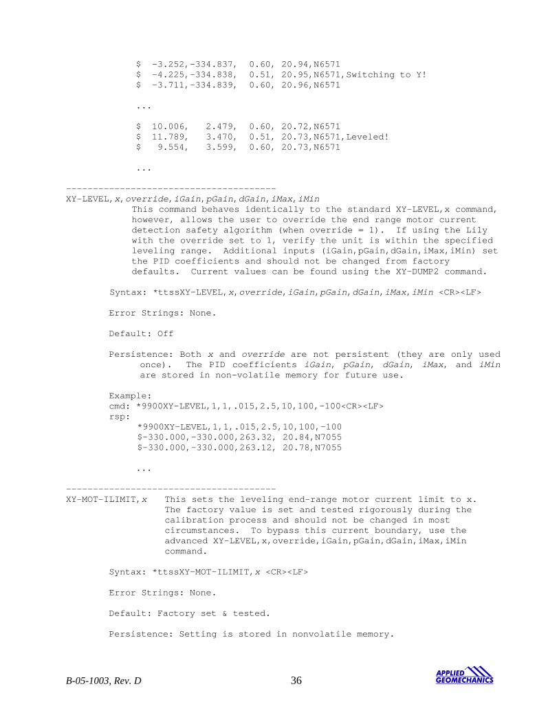
$ -3.252,-334.837, 0.60, 20.94,N6571 $ -4.225,-334.838, 0.51, 20.95,N6571,Switching to Y! $ -3.711,-334.839, 0.60, 20.96,N6571 ... $ 10.006, 2.479, 0.60, 20.72,N6571 $ 11.789, 3.470, 0.51, 20.73,N6571,Leveled! $ 9.554, 3.599, 0.60, 20.73,N6571 ...
--------------------------------------- XY-LEVEL,x,override,iGain,pGain,dGain,iMax,iMin This command behaves identically to the standard XY-LEVEL,x command, however, allows the user to override the end range motor current detection safety algorithm (when override = 1). If using the Lily with the override set to 1, verify the unit is within the specified leveling range. Additional inputs (iGain,pGain,dGain,iMax,iMin) set the PID coefficients and should not be changed from factory defaults. Current values can be found using the XY-DUMP2 command. Syntax: *ttssXY-LEVEL,x,override,iGain,pGain,dGain,iMax,iMin <CR><LF> Error Strings: None. Default: Off Persistence: Both x and override are not persistent (they are only used
once). The PID coefficients iGain, pGain, dGain, iMax, and iMin are stored in non-volatile memory for future use.
Example: cmd: *9900XY-LEVEL,1,1,.015,2.5,10,100,-100<CR><LF> rsp: *9900XY-LEVEL,1,1,.015,2.5,10,100,-100 $-330.000,-330.000,263.32, 20.84,N7055 $-330.000,-330.000,263.12, 20.78,N7055
...
--------------------------------------- XY-MOT-ILIMIT,x This sets the leveling end-range motor current limit to x. The factory value is set and tested rigorously during the calibration process and should not be changed in most circumstances. To bypass this current boundary, use the advanced XY-LEVEL,x,override,iGain,pGain,dGain,iMax,iMin command. Syntax: *ttssXY-MOT-ILIMIT,x <CR><LF> Error Strings: None. Default: Factory set & tested. Persistence: Setting is stored in nonvolatile memory.
B-05-1003, Rev. D 36
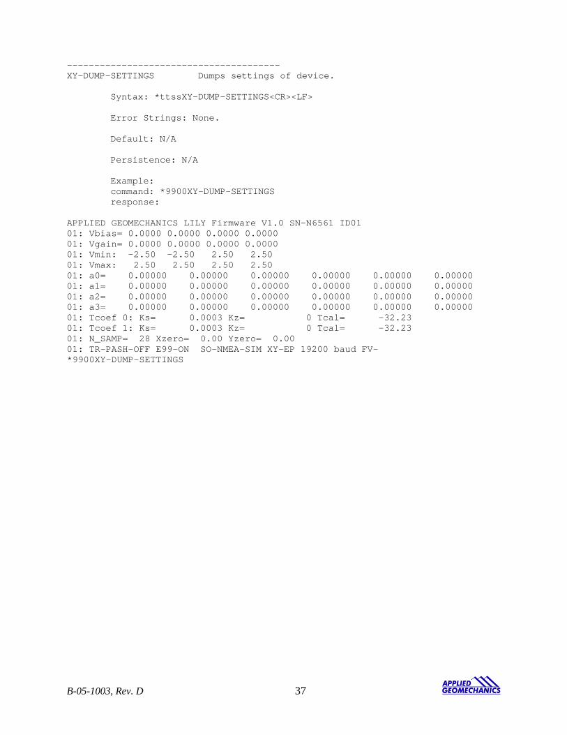
--------------------------------------- XY-DUMP-SETTINGS Dumps settings of device. Syntax: *ttssXY-DUMP-SETTINGS<CR><LF> Error Strings: None. Default: N/A Persistence: N/A Example: command: *9900XY-DUMP-SETTINGS response: APPLIED GEOMECHANICS LILY Firmware V1.0 SN-N6561 ID01 01: Vbias= 0.0000 0.0000 0.0000 0.0000 01: Vgain= 0.0000 0.0000 0.0000 0.0000 01: Vmin: -2.50 -2.50 2.50 2.50 01: Vmax: 2.50 2.50 2.50 2.50 01: a0= 0.00000 0.00000 0.00000 0.00000 0.00000 0.00000 01: a1= 0.00000 0.00000 0.00000 0.00000 0.00000 0.00000 01: a2= 0.00000 0.00000 0.00000 0.00000 0.00000 0.00000 01: a3= 0.00000 0.00000 0.00000 0.00000 0.00000 0.00000 01: Tcoef 0: Ks= 0.0003 Kz= 0 Tcal= -32.23 01: Tcoef 1: Ks= 0.0003 Kz= 0 Tcal= -32.23 01: N_SAMP= 28 Xzero= 0.00 Yzero= 0.00 01: TR-PASH-OFF E99-ON SO-NMEA-SIM XY-EP 19200 baud FV- *9900XY-DUMP-SETTINGS
B-05-1003, Rev. D 37
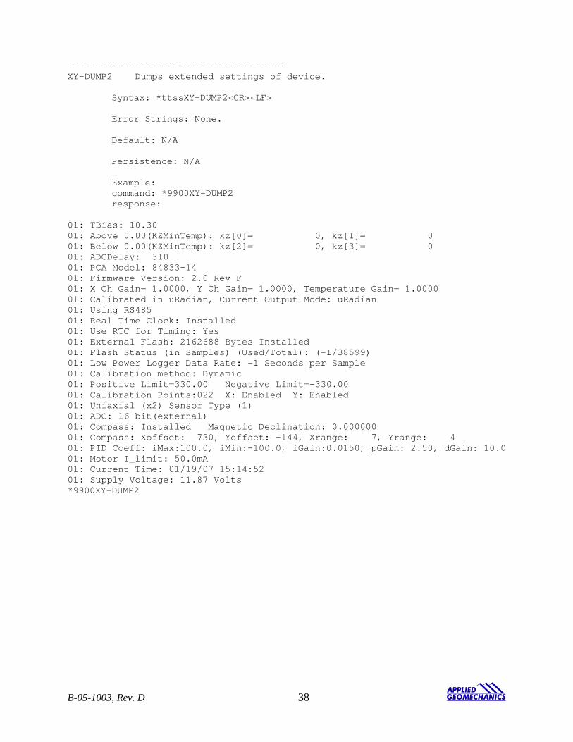
--------------------------------------- XY-DUMP2 Dumps extended settings of device. Syntax: *ttssXY-DUMP2<CR><LF> Error Strings: None. Default: N/A Persistence: N/A Example: command: *9900XY-DUMP2 response: 01: TBias: 10.30 01: Above 0.00(KZMinTemp): kz[0]= 0, kz[1]= 0 01: Below 0.00(KZMinTemp): kz[2]= 0, kz[3]= 0 01: ADCDelay: 310 01: PCA Model: 84833-14 01: Firmware Version: 2.0 Rev F 01: X Ch Gain= 1.0000, Y Ch Gain= 1.0000, Temperature Gain= 1.0000 01: Calibrated in uRadian, Current Output Mode: uRadian 01: Using RS485 01: Real Time Clock: Installed 01: Use RTC for Timing: Yes 01: External Flash: 2162688 Bytes Installed 01: Flash Status (in Samples) (Used/Total): (-1/38599) 01: Low Power Logger Data Rate: -1 Seconds per Sample 01: Calibration method: Dynamic 01: Positive Limit=330.00 Negative Limit=-330.00 01: Calibration Points:022 X: Enabled Y: Enabled 01: Uniaxial (x2) Sensor Type (1) 01: ADC: 16-bit(external) 01: Compass: Installed Magnetic Declination: 0.000000 01: Compass: Xoffset: 730, Yoffset: -144, Xrange: 7, Yrange: 4 01: PID Coeff: iMax:100.0, iMin:-100.0, iGain:0.0150, pGain: 2.50, dGain: 10.0 01: Motor I_limit: 50.0mA 01: Current Time: 01/19/07 15:14:52 01: Supply Voltage: 11.87 Volts *9900XY-DUMP2
B-05-1003, Rev. D 38
Appendix C Warranty and Limitation of Liability Standard goods (those listed in Applied Geomechanics’ published sales literature, excluding software) manufactured by Applied Geomechanics Inc. (AGI) are warranted against defects in materials and workmanship for twelve (12) months from the date of shipment from AGI’s premises with the following exceptions: Series 900 analog or digital clinometers are warranted against defects in materials and workmanship for 90 days from the delivery date. AGI will repair or replace (at its option) goods that prove to be defective during the warranty period provided that they are returned prepaid to AGI and: (a) that the goods were used at all times for the purpose for which they were designed and in accordance with any instructions given by AGI in respect of them, (b) that notice is received by AGI within 30 days of the defects becoming apparent, and (c) that return authorization is received from AGI prior to the goods being sent back. Should goods be damaged in transit to the Purchaser, AGI will accept no liability unless the Purchaser can show that such damage arose solely from AGI’s failure to pack the goods properly for shipment. Software products are warranted to perform substantially in accordance with their documentation for 90 days following your receipt of the software. AGI and its suppliers do not and cannot warrant the performance or results you may obtain by using the software or its documentation. In respect of goods or parts thereof manufactured by others and resold by AGI, AGI will pass on to the customer the benefit of any guarantee or warranty received by AGI from the original manufacturer insofar as such guarantee or warranty is assignable. ANY OTHER CONDITIONS OR WARRANTIES WHETHER EXPRESS OR IMPLIED BY STATUTE OR OTHERWISE ARE EXCLUDED. THE REMEDIES PROVIDED HEREIN ARE THE BUYER’S SOLE AND EXCLUSIVE REMEDIES. APPLIED GEOMECHANICS INC. SHALL NOT BE LIABLE FOR ANY DIRECT, INDIRECT, SPECIAL, INCIDENTAL OR CONSEQUENTIAL DAMAGES, INCLUDING LOST PROFITS OR LOST SAVINGS, WHETHER BASED ON CONTRACT, TORT, OR ANY OTHER LEGAL THEORY. THIS WARRANTY EXTENDS ONLY TO THE ORIGINAL PURCHASER AND IS EXPRESSLY IN LIEU OF ALL OTHER WARRANTIES, WHETHER OF MERCHANTABILITY OR FITNESS FOR ANY PARTICULAR USE, AND OF ALL OTHER OBLIGATIONS AND LIABILITIES OF ANY KIND AND CHARACTER. THERE ARE NO WARRANTIES WHICH EXTEND BEYOND THE DESCRIPTION ON THE FACE HEREOF. AGI’s liability arising out of the sale of its goods is expressly limited to the repair and/or replacement of defective parts or the cost of such repair and/or replacement. If software does not perform substantially in accordance with the documentation, the entire and exclusive liability and remedy shall be limited to either, at AGI’s option, the replacement of the software or the refund of the license fee you paid for the software. Liability for any other form of loss or damage is hereby expressly excluded. Customer shall indemnify AGI against any third party claim arising out of the use of goods and/or services supplied by AGI, including any claim arising directly or indirectly out of alleged negligence on the part of AGI, its employees, servants, representatives or agents.
B-05-1003, Rev. D 39
![Deep Borehole Field Test Laboratory and Borehole Testing ... · The characterization borehole (CB) is the smaller-diameter borehole (i.e., 21.6 cm [8.5”] diameter at total depth),](https://img.pdfslide.net/doc/110x75/5ebe68817151f10bcd35645a/deep-borehole-field-test-laboratory-and-borehole-testing-the-characterization.jpg)