Embed Size (px)
DESCRIPTION
transformer design
Citation preview
Trade of ElectricianStandards Based Apprenticeship
The Transformer
Phase 2
Module No. 2.1
Unit No. 2.1.10
COURSE NOTES
SOLAS Electrical Course Notes - Unit 2.1.10
Created by Gerry Ryan - Galway TC
Revision 1 April 2000 byGerry Ryan - Galway TCJohn Watters - Sligo TC
Revision 2 Nov. 2002 byGerry Ryan - Galway TC
Chris Ludlow - DundalkTC
Revision 3 Aug 2006 byChris Ludlow - DundalkTC
Revision 4, November 2013SOLAS
Published by
27-33 Upper Baggot StreetDublin 4Ireland
© SOLAS - 2013
All rights reserved. No part of this publication may be reproduced, stored in a retrieval system ortransmitted in any form or by any means, electronic, mechanical, photocopying, recording or otherwise, without
the prior permission of the copyright owner.
Revision 4, November 20132
SOLAS Electrical Course Notes - Unit 2.1.10
Table of Contents
INTRODUCTION................................................................................................................................... 4
THE TRANSFORMER.......................................................................................................................... 5
TRANSFORMER SYMBOLS................................................................................................................ 5
TRANSFORMER CONSTRUCTION....................................................................................................6
THE TRANSFORMER PRINCIPLE.....................................................................................................7
TURNS AND VOLTAGE RATIO.......................................................................................................... 9
STEP-DOWN TRANSFORMER.......................................................................................................... 10
STEP-UP TRANSFORMER................................................................................................................. 11
CURRENT RATIO............................................................................................................................... 12
POWER TRANSFER IN TRANSFORMERS......................................................................................14
POWER RATING OF TRANSFORMERS..........................................................................................15
TRANSFORMER LOSSES.................................................................................................................. 16
TRANSFORMER EFFICIENCY.........................................................................................................16
RESISTANCE TEST ON A TRANSFORMER...................................................................................17
Insulation Resistance Test on a Transformer.......................................................................................18
Revision 4, November 20133
SOLAS Electrical Course Notes - Unit 2.1.10
Introduction
Welcome to this section of your course, which is designed to introduce you the learner, to the transformer.
Objectives
By the end of this unit you will be able to:
Recognise and use appropriate symbols Understand the principle of the transformer State the relationship between turns ratio, voltage ratio and current ratio Explain the difference between a step down and a step up transformer Select a suitable power rating for a given load Test transformer winding resistance and insulation resistance
Reasons
The transformer is a very widely used piece of electrical equipment. The importance of understanding how it operates cannot be over emphasised.
Revision 4, November 20134
SOLAS Electrical Course Notes - Unit 2.1.10
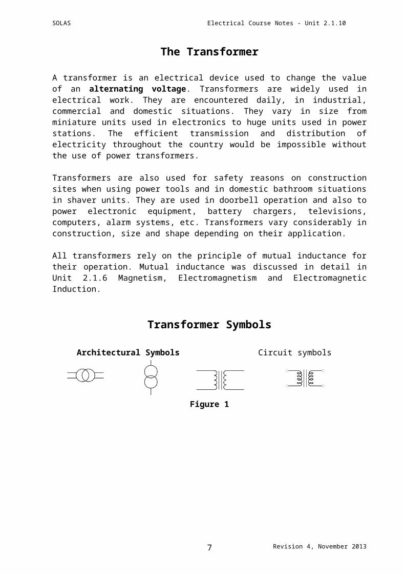
The Transformer
A transformer is an electrical device used to change the value of an alternating voltage. Transformers are widely used in electrical work. They are encountered daily, in industrial, commercial and domestic situations. They vary in size from miniature units used in electronics to huge units used in power stations. The efficient transmission and distribution of electricity throughout the country would be impossible without the use of power transformers.
Transformers are also used for safety reasons on construction sites when using power tools and in domestic bathroom situations in shaver units. They are used in doorbell operation and also to power electronic equipment, battery chargers, televisions, computers, alarm systems, etc. Transformers vary considerably in construction, size and shape depending on their application.
All transformers rely on the principle of mutual inductance for their operation. Mutual inductance was discussed in detail in Unit 2.1.6 Magnetism, Electromagnetism and Electromagnetic Induction.
Transformer Symbols
Architectural Symbols Circuit symbols
Figure 1
Revision 4, November 20135
SOLAS Electrical Course Notes - Unit 2.1.10
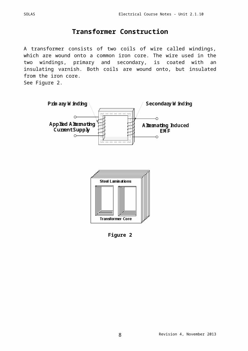
Transformer Construction
A transformer consists of two coils of wire called windings, which are wound onto a common iron core. The wire used in the two windings, primary and secondary, is coated with an insulating varnish. Both coils are wound onto, but insulated from the iron core.See Figure 2.
Figure 2
Revision 4, November 20136
SOLAS Electrical Course Notes - Unit 2.1.10
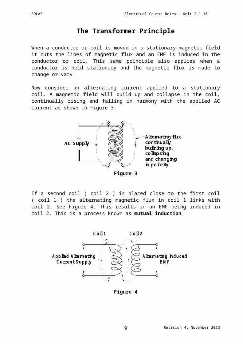
The Transformer Principle
When a conductor or coil is moved in a stationary magnetic field it cuts the lines of magnetic flux and an EMF is induced in the conductor or coil. This same principle also applies when a conductor is held stationary and the magnetic flux is made to change or vary.
Now consider an alternating current applied to a stationary coil. A magnetic field will build up and collapse in the coil, continually rising and falling in harmony with the applied AC current as shown in Figure 3.
Figure 3
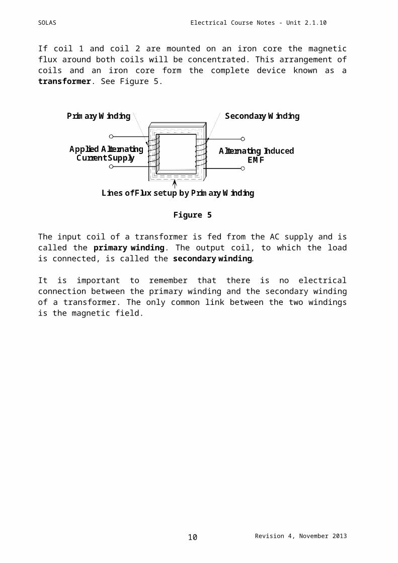
If a second coil ( coil 2 ) is placed close to the first coil ( coil 1 ) the alternating magnetic flux in coil 1 links with coil 2. See Figure 4. This results in an EMF being induced in coil 2. This is a process known as mutual induction.
Alternating InducedEMF
Applied AlternatingCurrent Supply
Coil 1 Coil 2
Figure 4
Revision 4, November 20137
SOLAS Electrical Course Notes - Unit 2.1.10
If coil 1 and coil 2 are mounted on an iron core the magnetic flux around both coils will be concentrated. This arrangement of coils and an iron core form the complete device known as a transformer. See Figure 5.
Figure 5
The input coil of a transformer is fed from the AC supply and is called the primary winding. The output coil, to which the load is connected, is called the secondary winding.
It is important to remember that there is no electrical connection between the primary winding and the secondary winding of a transformer. The only common link between the two windings is the magnetic field.
Revision 4, November 20138
SOLAS Electrical Course Notes - Unit 2.1.10
Turns and Voltage Ratio
The relationship between the number of primary winding turns (N1) and the number of secondary winding turns (N2) together with the primary input voltage (U1) and the secondary output voltage (U2) can be expressed as a ratio or equation as shown below.
U1 N1
=U2 N2
Where:N1 = Number of Primary Winding turnsN2 = Number of Secondary Winding turnsU1 = Primary Input VoltageU2 = Secondary Output Voltage
This formula can be transformed to find any one unknown provided the other three are known.
U2 x N1 U1 x N2
U1 = U2 = N2 N1
U1 x N2 U2 x N1
N1 = N2 = U2 U1
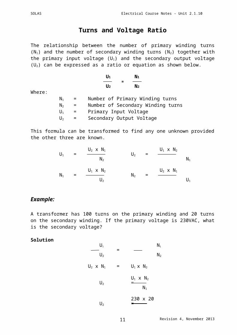
Example:
A transformer has 100 turns on the primary winding and 20 turns on the secondary winding. If the primary voltage is 230VAC, what is the secondary voltage?
Solution U1 N1
= U2 N2
U2 x N1 = U1 x N2
U1 x N2
U2 = N1
230 x 20 U2 =
100
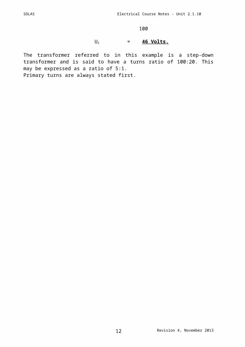
U2 = 46 Volts.
The transformer referred to in this example is a step-down transformer and is said to have a turns ratio of 100:20. This may be expressed as a ratio of 5:1.Primary turns are always stated first.
Revision 4, November 20139
SOLAS Electrical Course Notes - Unit 2.1.10
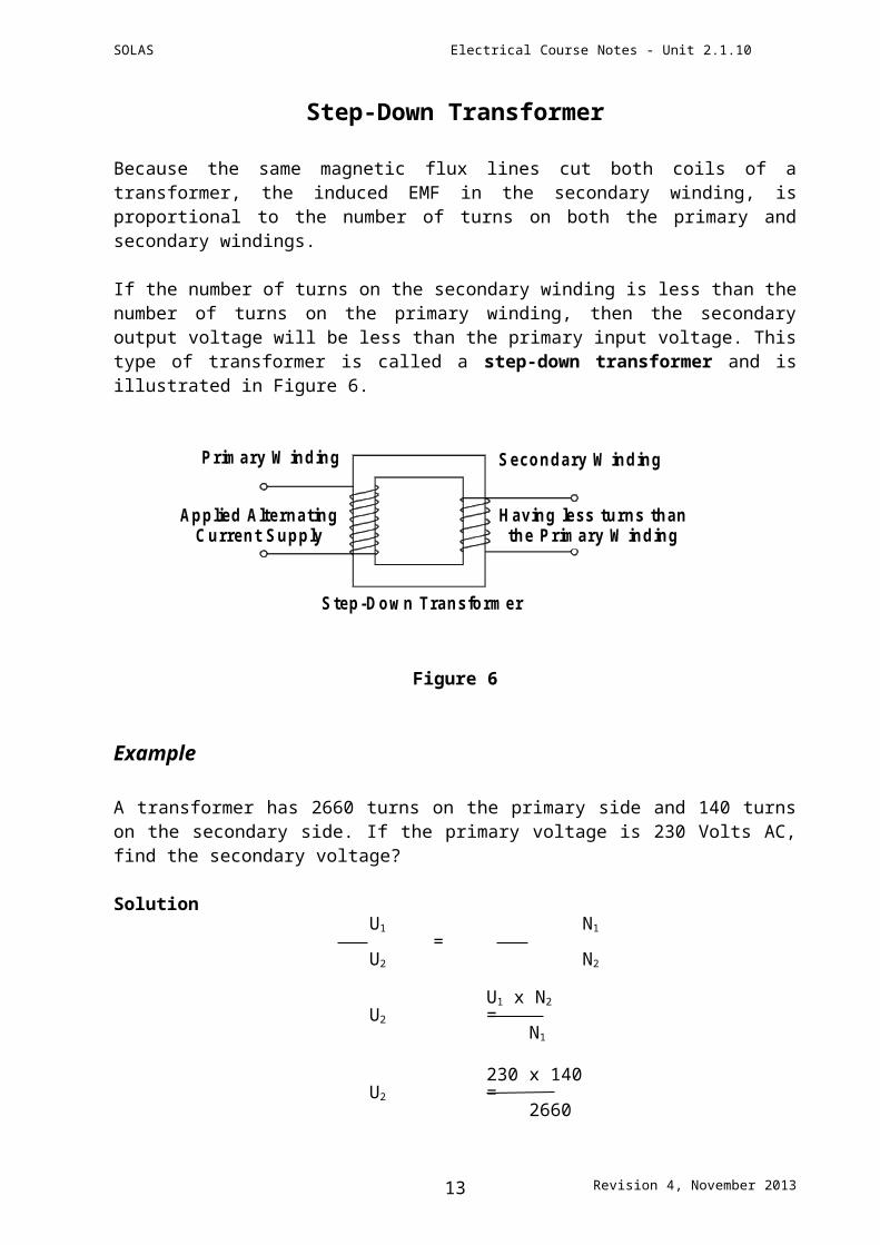
Step-Down Transformer
Because the same magnetic flux lines cut both coils of a transformer, the induced EMF in the secondary winding, is proportional to the number of turns on both the primary and secondary windings.
If the number of turns on the secondary winding is less than the number of turns on the primary winding, then the secondary output voltage will be less than the primary input voltage. This type of transformer is called a step-down transformer and is illustrated in Figure 6.
Applied AlternatingCurrent Supply
Primary W inding Secondary W inding
Having less turns thanthe Primary W inding
Step-Down Transformer
Figure 6
Example
A transformer has 2660 turns on the primary side and 140 turns on the secondary side. If the primary voltage is 230 Volts AC, find the secondary voltage?
Solution U1 N1
= U2 N2
U1 x N2
U2 = N1
230 x 140 U2 =
2660
U2 = 12.10 Volts.
This is a step down transformer and is said to have a turns ratio of 2,660:140 or 19:1.
Revision 4, November 201310
SOLAS Electrical Course Notes - Unit 2.1.10
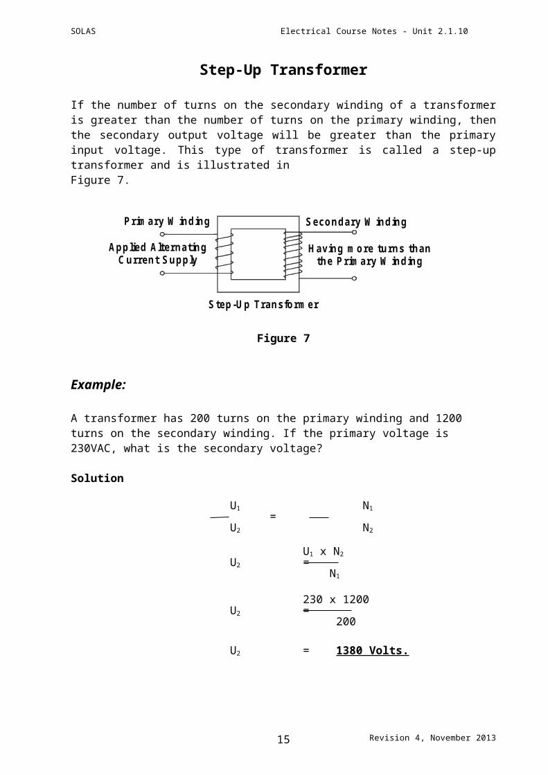
Step-Up Transformer
If the number of turns on the secondary winding of a transformer is greater than the number of turns on the primary winding, then the secondary output voltage will be greater than the primary input voltage. This type of transformer is called a step-up transformer and is illustrated inFigure 7.
Secondary W indingPrimary W inding
Applied AlternatingCurrent Supply
Having more turns thanthe Primary W inding
Step-Up Transformer
Figure 7
Example:
A transformer has 200 turns on the primary winding and 1200 turns on the secondary winding. If the primary voltage is 230VAC, what is the secondary voltage?
Solution
U1 N1
= U2 N2
U1 x N2
U2 = N1
230 x 1200 U2 =
200
U2 = 1380 Volts.
This is a step-up transformer and is said to have a turns ratio of 200:1200 or 1:6.
Revision 4, November 201311
SOLAS Electrical Course Notes - Unit 2.1.10
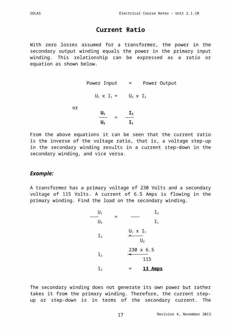
Current Ratio
With zero losses assumed for a transformer, the power in the secondary output winding equals the power in the primary input winding. This relationship can be expressed as a ratio or equation as shown below.
Power Input = Power Output
U1 x I1 = U2 x I2
orU1 I2
=U2 I1
From the above equations it can be seen that the current ratio is the inverse of the voltage ratio, that is, a voltage step-up in the secondary winding results in a current step-down in the secondary winding, and vice versa.
Example:
A transformer has a primary voltage of 230 Volts and a secondary voltage of 115 Volts. A current of 6.5 Amps is flowing in the primary winding. Find the load on the secondary winding.
U1 I2
= U2 I1
U1 x I1
I2 = U2
230 x 6.5 I2 =
115
I2 = 13 Amps
The secondary winding does not generate its own power but rather takes it from the primary winding. Therefore, the current step-up or step-down is in terms of the secondary current. The primary current is determined by the load resistance across the secondary winding. These points are illustrated by the following example.
Revision 4, November 201312
SOLAS Electrical Course Notes - Unit 2.1.10
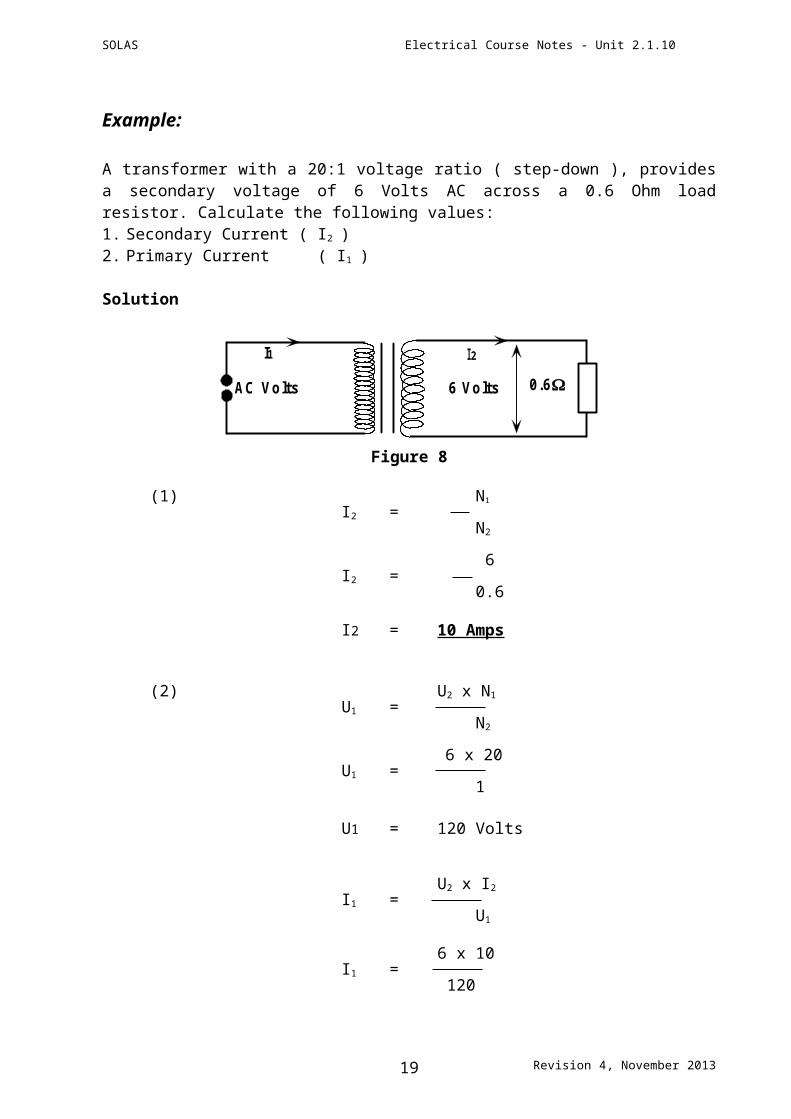
Example:
A transformer with a 20:1 voltage ratio ( step-down ), provides a secondary voltage of 6 Volts AC across a 0.6 Ohm load resistor. Calculate the following values:1. Secondary Current ( I2 )2. Primary Current ( I1 )
Solution
AC Volts
I1 I2
6 Volts 0.6
Figure 8
(1) N1
I2 = N2
6I2 =
0.6
I2 = 10 Amps
(2) U2 x N1
U1 = N2
6 x 20U1 =
1
U1 = 120 Volts
U2 x I2
I1 = U1
6 x 10I1 =
120
I1 = 0.5 Amp
Revision 4, November 201313
SOLAS Electrical Course Notes - Unit 2.1.10
Power Transfer in Transformers
U1 = 120V 0.6U2 = 6V
I1 = 0.5A I2 = 10A
Figure 9
In Figure 9 we can now look at the circuit from the previous example, redrawn with the calculated voltage and current values included. The power in the primary winding of a transformer transfers to the secondary. This is illustrated in the example below.
Power in Primary = Power in Secondary
U1 x I1 = U2 x I2
120 x 0.5 = 6 x 10
60 VA = 60 VA
Remember that the winding with the higher voltage has the lower current and the winding with the lower voltage has the higher current. In the above example the voltage ratio is 20:1 while the current ratio is 1:20. The secondary winding would need to be wound with wire of a larger cross sectional area than that of the primary winding in order to carry the larger current.
Reflecting on Formulae U1 N1
= U2 N2
and U1 I2
= U2 I1
Therefore
U1 N1 I2
= = U2 N2 I1
And so
N1 I2
= N2 I1
Revision 4, November 201314
SOLAS Electrical Course Notes - Unit 2.1.10
Power Rating of Transformers
The power rating of a transformer may be calculated by multiplying the secondary AC voltage by the full load secondary AC current.
Rating = Secondary Voltage x Secondary Current
Rating = V x A ( U2 x I2 )
Rating = VA
A rating quoted in VA will apply to small transformers. The rating of larger transformers will be quoted in kVA or MVA
VA That is = kVA
1000
VA or = MVA
1000,000
kVA
or = MVA 1000
Revision 4, November 201315
SOLAS Electrical Course Notes - Unit 2.1.10
Transformer Losses
Iron Losses in a Transformer
Eddy currents are induced into the transformer core. These unwanted eddy currents, cause heating of the core. They represent a loss in the transformer and are referred to as iron losses. The iron core is made up of steel laminations, to reduce eddy currents to a minimum. Silicon steel is generally used as its magnetism is easily reversed.
Copper Losses in a Transformer
Copper losses are due to, current flowing through the resistance of the windings, and are often referred to as the I2R losses ( P = I2 x R ). The greater the current flow through the windings, the greater the copper losses.
Transformer Efficiency
A transformer has no moving parts and is a highly efficient device. Normal transformer efficiency is around 98%. In general, the larger the transformer the higher its efficiency. Efficiency is defined as the ratio of power output to power input.
Warning
Great care must be exercised when connecting the primary and secondary windings of transformers.The rated voltage of the windings must never be exceeded otherwise damage will result to equipment, property and may also present a danger to the Health and Safety of person(s).
Revision 4, November 201316
SOLAS Electrical Course Notes - Unit 2.1.10
Resistance Test on a Transformer
Connect an ohmmeter across the two ends of the primary winding of the transformer and record the resistance. See Figure 10.
PrimaryW inding
SecondaryW inding
Figure 10
Connect an ohmmeter across the two ends of the secondary winding of the transformer and record the resistance. See Figure 11.
PrimaryW inding
SecondaryW inding
Figure 11
Conclusion:
If an infinite resistance is obtained in either of the two tests this will indicate an open circuit in that winding and hence non-function of the transformer.
The resistance values of both windings may differ quite substantially due to the difference in the number of turns on each winding and also the difference in the cross sectional area of the wire in the primary and secondary windings.
To determine if the resistance values measured are correct, the manufacturer’s specifications will have to be obtained and both resistance readings compared.
Revision 4, November 201317
SOLAS Electrical Course Notes - Unit 2.1.10
Insulation Resistance Test on a Transformer
Class 1 Transformer
Insulation resistance tests between each winding and earth
Primary Winding to core Secondary winding to core
Insulation resistance test between windings
PrimaryW inding
SecondaryW inding
M 500V
Temporary short for the duration of the test
The minimum insulation resistance value accepted in each of the above tests is 2M.
A 500V Insulation Resistance Test is suitable for 110 – 400 Volt transformers.
Revision 4, November 201318
SOLAS Electrical Course Notes - Unit 2.1.10
Class 2 Transformer
Double Insulated Symbol
Insulation Resistance Test Between Windings
PrimaryW inding
SecondaryW inding
M 500V
Temporary short for the duration of the test
The minimum insulation resistance value accepted in the test is 2 M.
Revision 4, November 201319


