Embed Size (px)
Citation preview
Magneto-Optic Tracking of a FlexibleLaparoscopic Ultrasound Transducer for
Laparoscope Augmentation
Marco Feuerstein1, Tobias Reichl1, Jakob Vogel1, Armin Schneider2,Hubertus Feussner2, and Nassir Navab1
1 Computer-Aided Medical Procedures (CAMP), TUM, Munich, Germany2 Department of Surgery, Klinikum rechts der Isar, TUM, Munich, Germany
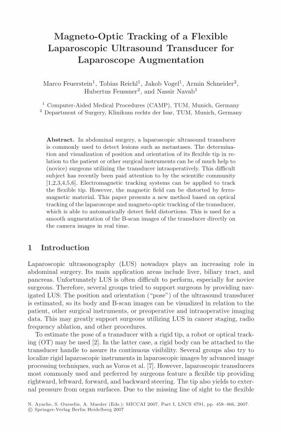
Abstract. In abdominal surgery, a laparoscopic ultrasound transduceris commonly used to detect lesions such as metastases. The determina-tion and visualization of position and orientation of its flexible tip in re-lation to the patient or other surgical instruments can be of much help to(novice) surgeons utilizing the transducer intraoperatively. This difficultsubject has recently been paid attention to by the scientific community[1,2,3,4,5,6]. Electromagnetic tracking systems can be applied to trackthe flexible tip. However, the magnetic field can be distorted by ferro-magnetic material. This paper presents a new method based on opticaltracking of the laparoscope and magneto-optic tracking of the transducer,which is able to automatically detect field distortions. This is used for asmooth augmentation of the B-scan images of the transducer directly onthe camera images in real time.
1 Introduction
Laparoscopic ultrasonography (LUS) nowadays plays an increasing role inabdominal surgery. Its main application areas include liver, biliary tract, andpancreas. Unfortunately LUS is often difficult to perform, especially for novicesurgeons. Therefore, several groups tried to support surgeons by providing nav-igated LUS: The position and orientation (“pose”) of the ultrasound transduceris estimated, so its body and B-scan images can be visualized in relation to thepatient, other surgical instruments, or preoperative and intraoperative imagingdata. This may greatly support surgeons utilizing LUS in cancer staging, radiofrequency ablation, and other procedures.
To estimate the pose of a transducer with a rigid tip, a robot or optical track-ing (OT) may be used [2]. In the latter case, a rigid body can be attached to thetransducer handle to assure its continuous visibility. Several groups also try tolocalize rigid laparoscopic instruments in laparoscopic images by advanced imageprocessing techniques, such as Voros et al. [7]. However, laparoscopic transducersmost commonly used and preferred by surgeons feature a flexible tip providingrightward, leftward, forward, and backward steering. The tip also yields to exter-nal pressure from organ surfaces. Due to the missing line of sight to the flexible
N. Ayache, S. Ourselin, A. Maeder (Eds.): MICCAI 2007, Part I, LNCS 4791, pp. 458–466, 2007.c© Springer-Verlag Berlin Heidelberg 2007
Magneto-Optic Tracking of a Flexible Laparoscopic Ultrasound Transducer 459
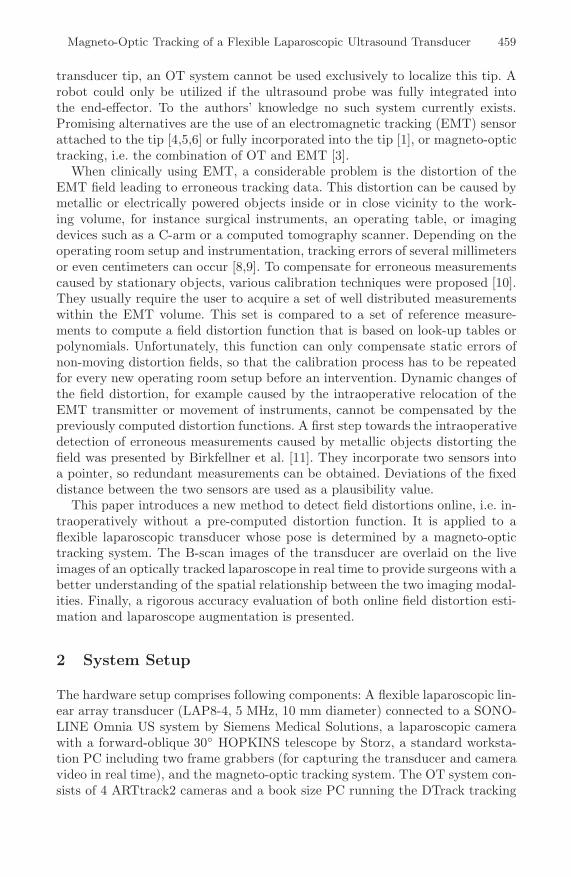
transducer tip, an OT system cannot be used exclusively to localize this tip. Arobot could only be utilized if the ultrasound probe was fully integrated intothe end-effector. To the authors’ knowledge no such system currently exists.Promising alternatives are the use of an electromagnetic tracking (EMT) sensorattached to the tip [4,5,6] or fully incorporated into the tip [1], or magneto-optictracking, i.e. the combination of OT and EMT [3].
When clinically using EMT, a considerable problem is the distortion of theEMT field leading to erroneous tracking data. This distortion can be caused bymetallic or electrically powered objects inside or in close vicinity to the work-ing volume, for instance surgical instruments, an operating table, or imagingdevices such as a C-arm or a computed tomography scanner. Depending on theoperating room setup and instrumentation, tracking errors of several millimetersor even centimeters can occur [8,9]. To compensate for erroneous measurementscaused by stationary objects, various calibration techniques were proposed [10].They usually require the user to acquire a set of well distributed measurementswithin the EMT volume. This set is compared to a set of reference measure-ments to compute a field distortion function that is based on look-up tables orpolynomials. Unfortunately, this function can only compensate static errors ofnon-moving distortion fields, so that the calibration process has to be repeatedfor every new operating room setup before an intervention. Dynamic changes ofthe field distortion, for example caused by the intraoperative relocation of theEMT transmitter or movement of instruments, cannot be compensated by thepreviously computed distortion functions. A first step towards the intraoperativedetection of erroneous measurements caused by metallic objects distorting thefield was presented by Birkfellner et al. [11]. They incorporate two sensors intoa pointer, so redundant measurements can be obtained. Deviations of the fixeddistance between the two sensors are used as a plausibility value.
This paper introduces a new method to detect field distortions online, i.e. in-traoperatively without a pre-computed distortion function. It is applied to aflexible laparoscopic transducer whose pose is determined by a magneto-optictracking system. The B-scan images of the transducer are overlaid on the liveimages of an optically tracked laparoscope in real time to provide surgeons with abetter understanding of the spatial relationship between the two imaging modal-ities. Finally, a rigorous accuracy evaluation of both online field distortion esti-mation and laparoscope augmentation is presented.
2 System Setup
The hardware setup comprises following components: A flexible laparoscopic lin-ear array transducer (LAP8-4, 5 MHz, 10 mm diameter) connected to a SONO-LINE Omnia US system by Siemens Medical Solutions, a laparoscopic camerawith a forward-oblique 30◦ HOPKINS telescope by Storz, a standard worksta-tion PC including two frame grabbers (for capturing the transducer and cameravideo in real time), and the magneto-optic tracking system. The OT system con-sists of 4 ARTtrack2 cameras and a book size PC running the DTrack tracking
460 M. Feuerstein et al.
software. The EMT system in use is a 3D Guidance unit of Ascension equippedwith a mid-range transmitter and insulated 1.3 mm sensors, which have a totaldiameter of 1.7 mm including the vinyl tubing. Time synchronization of all datastreams and visualization is performed by CAMPAR [12].
3 Methods
In addition to an OT body, which is attached to the transducer handle (below re-ferred to as “rigid body”), two EMT sensors are attached to the transducer shaft:One to the flexible tip (“flexible sensor”), the other one to the rigid part (“rigidsensor”), as close to each other as possible. Another OT body is mounted onthe EMT transmitter (“transmitter body”). This setup allows us to co-calibrateEMT and OT and to obtain redundant tracking information of the rigid part ofthe transducer shaft, which is important to detect EMT errors. Finally, two OTbodies are attached to the laparoscopic camera, one to the head (“laparoscopebody”) and another one to the telescope to adjust for telescope rotations.
3.1 System Calibration
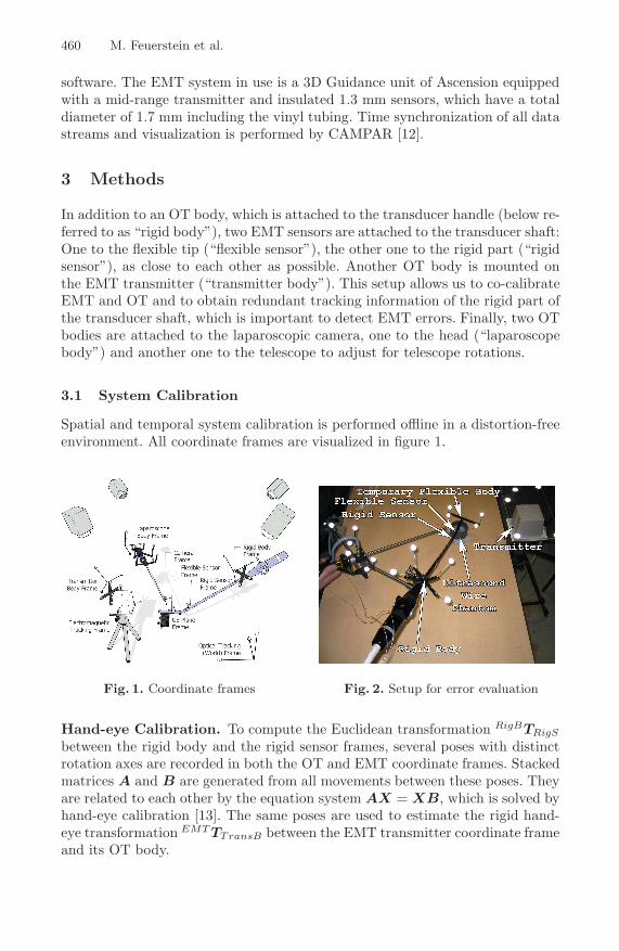
Spatial and temporal system calibration is performed offline in a distortion-freeenvironment. All coordinate frames are visualized in figure 1.
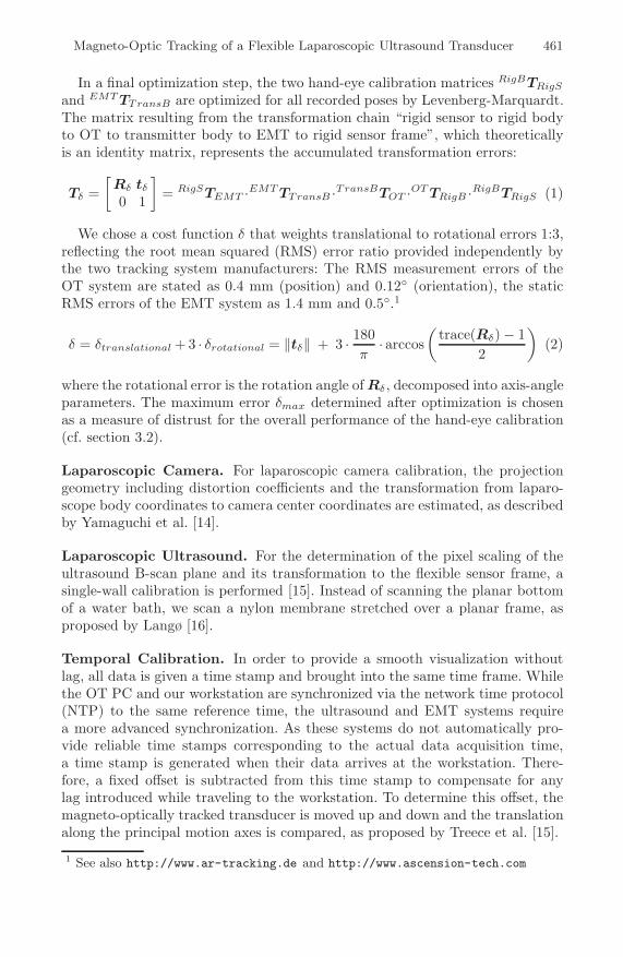
Fig. 1. Coordinate frames Fig. 2. Setup for error evaluation
Hand-eye Calibration. To compute the Euclidean transformation RigBTRigS
between the rigid body and the rigid sensor frames, several poses with distinctrotation axes are recorded in both the OT and EMT coordinate frames. Stackedmatrices A and B are generated from all movements between these poses. Theyare related to each other by the equation system AX = XB, which is solved byhand-eye calibration [13]. The same poses are used to estimate the rigid hand-eye transformation EMT TTransB between the EMT transmitter coordinate frameand its OT body.
Magneto-Optic Tracking of a Flexible Laparoscopic Ultrasound Transducer 461
In a final optimization step, the two hand-eye calibration matrices RigBTRigS
and EMT TTransB are optimized for all recorded poses by Levenberg-Marquardt.The matrix resulting from the transformation chain “rigid sensor to rigid bodyto OT to transmitter body to EMT to rigid sensor frame”, which theoreticallyis an identity matrix, represents the accumulated transformation errors:
Tδ =[
Rδ tδ
0 1
]= RigSTEMT ·EMT TTransB ·TransBTOT ·OT TRigB ·RigBTRigS (1)
We chose a cost function δ that weights translational to rotational errors 1:3,reflecting the root mean squared (RMS) error ratio provided independently bythe two tracking system manufacturers: The RMS measurement errors of theOT system are stated as 0.4 mm (position) and 0.12◦ (orientation), the staticRMS errors of the EMT system as 1.4 mm and 0.5◦.1
δ = δtranslational + 3 · δrotational = ‖tδ‖ + 3 · 180π
· arccos(
trace(Rδ) − 12
)(2)
where the rotational error is the rotation angle of Rδ, decomposed into axis-angleparameters. The maximum error δmax determined after optimization is chosenas a measure of distrust for the overall performance of the hand-eye calibration(cf. section 3.2).
Laparoscopic Camera. For laparoscopic camera calibration, the projectiongeometry including distortion coefficients and the transformation from laparo-scope body coordinates to camera center coordinates are estimated, as describedby Yamaguchi et al. [14].
Laparoscopic Ultrasound. For the determination of the pixel scaling of theultrasound B-scan plane and its transformation to the flexible sensor frame, asingle-wall calibration is performed [15]. Instead of scanning the planar bottomof a water bath, we scan a nylon membrane stretched over a planar frame, asproposed by Langø [16].
Temporal Calibration. In order to provide a smooth visualization withoutlag, all data is given a time stamp and brought into the same time frame. Whilethe OT PC and our workstation are synchronized via the network time protocol(NTP) to the same reference time, the ultrasound and EMT systems requirea more advanced synchronization. As these systems do not automatically pro-vide reliable time stamps corresponding to the actual data acquisition time,a time stamp is generated when their data arrives at the workstation. There-fore, a fixed offset is subtracted from this time stamp to compensate for anylag introduced while traveling to the workstation. To determine this offset, themagneto-optically tracked transducer is moved up and down and the translationalong the principal motion axes is compared, as proposed by Treece et al. [15].
1 See also http://www.ar-tracking.de and http://www.ascension-tech.com
462 M. Feuerstein et al.
3.2 Online Error Estimation
Intraoperatively, every measured pose of the rigid sensor is transformed applyingequation 1. If a corresponding error δ is determined, which is bigger than thedistrust level δmax, the surgical staff is automatically warned. Such errors areoften caused by dynamic or static field distortions. Additionally, as the flexiblesensor is in close proximity to the rigid one, its measurements will be most likelyaffected by these distortions as well.
In order to also approximate a correction of erroneous measurements of theflexible sensor, a simple approach is to apply the deviation between the previ-ously hand-eye calibrated (“calib”) and the measured (“meas”) transformationof the rigid sensor to the measured flexible sensor transformation, all relativelyto the fixed OT (world) reference frame:
OT RFlexS(corr) = OT RRigidS(meas)T · OT RRigidS(calib) · OT RFlexS(meas) (3)
OT tFlexS(corr) = −OT tRigidS(meas) + OT tRigidS(calib) + OT tFlexS(meas) (4)
4 Experimental Evaluation Results
To avoid too many outliers, all EMT measurements were acquired in a restrictedvolume of 20–36 cm for x, and ±15 cm for y and z.
4.1 Ultrasound Calibration Error
After acquiring 40 flexible sensor poses and their corresponding lines that wereautomatically detected in the B-scan images, the calibration matrix was com-puted using the Levenberg-Marquardt optimizer. To determine the ultrasoundcalibration accuracy, a single EMT sensor with tip coordinates given in the EMTframe was submerged into the water bath. Its tip was segmented manually in 5regions of the B-scan plane, which was repeated for 4 poses of the transducerdiffering from the ones used during calibration. The tip coordinates were trans-formed into the B-scan plane coordinates and compared to the segmented tipcoordinates (scaled to mm). An RMS error of 1.69 mm with standard deviationof 0.51 mm and maximum error of 2.39 mm was obtained.
4.2 Laparoscope Augmentation Error
In order to estimate the laparoscope augmentation errors automatically, an ad-ditional OT body (“flexible body”) was temporarily attached to the transducertip and co-calibrated to the flexible sensor by another hand-eye calibration (cf.section 3.1 and figure 2). One marker of the flexible body was chosen as a ref-erence and automatically segmented whenever visible in the laparoscopic video.We compared its center coordinates to the projection of its respective OT coordi-nates onto the image plane. Additionally, the corresponding EMT measurementsas well as their approximated corrections were projected using the previously de-termined hand-eye calibration transformations.
Magneto-Optic Tracking of a Flexible Laparoscopic Ultrasound Transducer 463
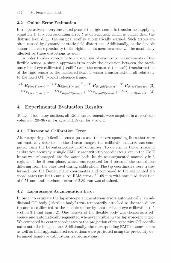
Fig. 3. RMS projection errors
Evaluation data wasrecorded using a laparo-scope-to-marker distanceof 5 to 10 cm, whichis a typical intraoper-ative working distance.The current distance canbe recovered from OTdata and the camera cal-ibration parameters. Wealso used this informa-tion to scale pixel units tomm.
For each of six evalua-tion series, the transducerwas fixed at a differentpose and the laparoscopewas used to measure the projected distances from five differing poses, each in anundistorted and a distorted environment. To distort the EMT field, two alterna-tives were evaluated. A metal plate was placed on the table to simulate primarilystatic distortions caused for instance by an operating table. For dynamic distor-tions, a steel rod of 10 mm diameter was brought close to the transducer tosimulate a surgical instrument, changing its proximity and angle to the trans-ducer in five measurements.
The RMS errors are given in figure 3. For each of the six series, we plotted theerrors of the three distortion cases (no distortion, static, and dynamic distortion),each scenario with our simple correction function enabled and disabled. Whilewe have been able to predict and correct static interferences with high reliability,dynamic distortions yielded even worse results when attempting a correction.
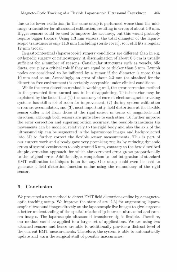
In order to evaluate our distrust function statistically, we computed the dis-trust level (cf. equation 2) for each of the poses. An offset between the segmentedmarker and the EMT projections of more than 2 mm was regarded as erroneousmeasurement. In this case, we expect a distrust level δ of more than δmax (duringhand-eye calibration, δmax was empirically determined to be 20). We defined thefollowing cases for our evaluation:
– A true positive is a measurement, in which the EMT error was above 2 mmwith a distrust level of above 20 – the detector rejected an erroneous readingcorrectly.
– A true negative is a measurement, in which the EMT error was below 2 mmwith a distrust level below 20 – we correctly accepted the original EMT data.
– A false positive (type 1 error) is a measurement, in which the EMT errorwas below 2 mm, but the distrust level above 20 – we have not been able todetect a correct value and rejected it without necessity.
464 M. Feuerstein et al.
Table 1. Distortion detection rateby our distrust level
distortion true falsew/o: positive 40.0% 10.0%
negative 30.0% 20.0%static: positive 100.0% 0.0%
negative 0.0% 0.0%dynamic: positive 73.8% 13.8%
negative 12.4% 0.0%avg: positive 71.3% 7.9%
negative 14.1% 6.7%
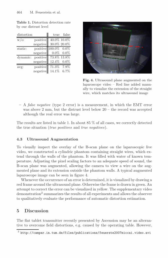
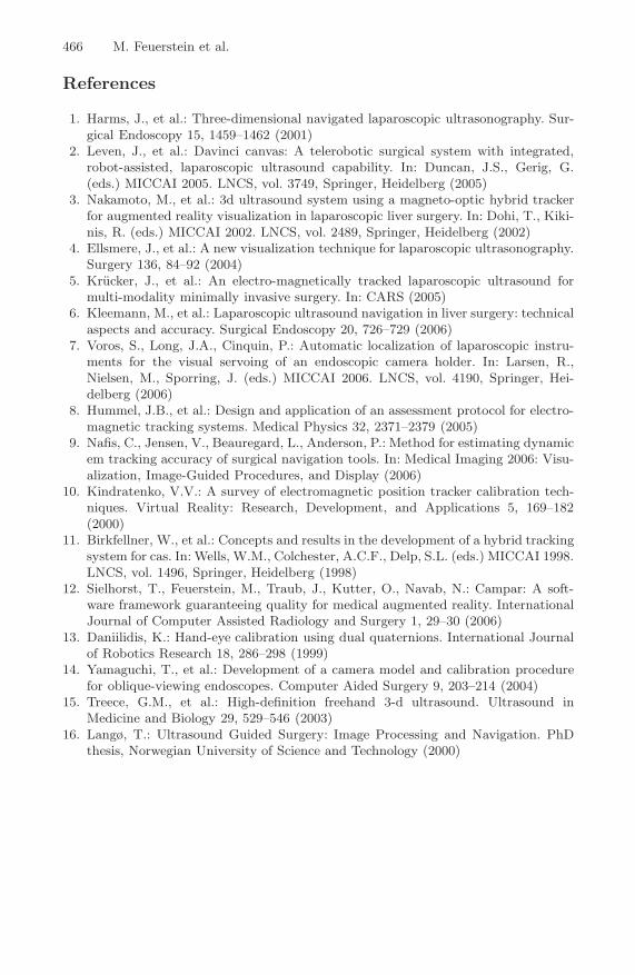
Fig. 4. Ultrasound plane augmented on thelaparoscope video – Red line added manu-ally to visualize the extension of the straightwire, which matches its ultrasound image
– A false negative (type 2 error) is a measurement, in which the EMT errorwas above 2 mm, but the distrust level below 20 – the record was acceptedalthough the real error was large.
The results are listed in table 1. In about 85 % of all cases, we correctly detectedthe true situation (true positives and true negatives).
4.3 Ultrasound Augmentation
To visually inspect the overlay of the B-scan plane on the laparoscopic livevideo, we constructed a cylindric phantom containing straight wires, which ex-tend through the walls of the phantom. It was filled with water of known tem-perature. Adjusting the pixel scaling factors to an adequate speed of sound, theB-scan plane was augmented, allowing the camera to view a wire on the aug-mented plane and its extension outside the phantom walls. A typical augmentedlaparoscope image can be seen in figure 4.
Whenever the occurrence of an error is determined, it is visualized by drawing ared frame around the ultrasound plane. Otherwise the frame is drawn in green. Anattempt to correct the error can be visualized in yellow. The supplementary videodemonstration2 summarizes the results of all experiments and allows the observerto qualitatively evaluate the performance of automatic distortion estimation.
5 Discussion
The flat tablet transmitter recently presented by Ascension may be an alterna-tive to overcome field distortions, e.g. caused by the operating table. However,2 http://campar.in.tum.de/files/publications/feuerste2007miccai.video.avi
Magneto-Optic Tracking of a Flexible Laparoscopic Ultrasound Transducer 465
due to its lower excitation, in the same setup it performed worse than the mid-range transmitter for ultrasound calibration, resulting in errors of about 4-8 mm.Bigger sensors could be used to improve the accuracy, but this would probablyrequire bigger trocars. Using 1.3 mm sensors, the total diameter of the laparo-scopic transducer is only 11.8 mm (including sterile cover), so it still fits a regular12 mm trocar.
In gastrointestinal (laparoscopic) surgery conditions are different than in e.g.orthopedic surgery or neurosurgery. A discrimination of about 0.5 cm is usuallysufficient for a number of reasons. Canalicular structures such as vessels, bileducts, etc. play a critical role if they are equal to or thicker than 5 mm. Lymphnodes are considered to be inflicted by a tumor if the diameter is more than10 mm and so on. Accordingly, an error of about 2-3 mm (as obtained for thedistortion free environment) is certainly acceptable under clinical conditions.
While the error detection method is working well, the error correction methodin the presented form turned out to be disappointing. This behavior may beexplained by the facts, that (1) the accuracy of current electromagnetic trackingsystems has still a lot of room for improvement, (2) during system calibrationerrors are accumulated, and (3), most importantly, field distortions at the flexiblesensor differ a lot from those at the rigid sensor in terms of magnitude anddirection, although both sensors are quite close to each other. To further improvethe error correction and superimposition accuracy, the possible transducer tipmovements can be modeled relatively to the rigid body and also the axis of theultrasound tip can be segmented in the laparoscope images and backprojectedinto 3D to further correct the flexible sensor measurements. This is part ofour current work and already gave very promising results by reducing dynamicerrors of several centimeters to only around 5 mm, contrary to the here describedsimple correction approach, for which the corrected error grows proportionallyto the original error. Additionally, a comparison to and integration of standardEMT calibration techniques is on its way. Our setup could even be used togenerate a field distortion function online using the redundancy of the rigidsensor.
6 Conclusion
We presented a new method to detect EMT field distortions online by a magneto-optic tracking setup. We improve the state of art [2,3] for augmenting laparo-scopic ultrasound images directly on the laparoscopic live images to give surgeonsa better understanding of the spatial relationship between ultrasound and cam-era images. The laparoscopic ultrasound transducer tip is flexible. Therefore,our method could be applied to a larger set of applications. We are using twoattached sensors and hence are able to additionally provide a distrust level ofthe current EMT measurements. Therefore, the system is able to automaticallyupdate and warn the surgical staff of possible inaccuracies.
466 M. Feuerstein et al.
References
1. Harms, J., et al.: Three-dimensional navigated laparoscopic ultrasonography. Sur-gical Endoscopy 15, 1459–1462 (2001)
2. Leven, J., et al.: Davinci canvas: A telerobotic surgical system with integrated,robot-assisted, laparoscopic ultrasound capability. In: Duncan, J.S., Gerig, G.(eds.) MICCAI 2005. LNCS, vol. 3749, Springer, Heidelberg (2005)
3. Nakamoto, M., et al.: 3d ultrasound system using a magneto-optic hybrid trackerfor augmented reality visualization in laparoscopic liver surgery. In: Dohi, T., Kiki-nis, R. (eds.) MICCAI 2002. LNCS, vol. 2489, Springer, Heidelberg (2002)
4. Ellsmere, J., et al.: A new visualization technique for laparoscopic ultrasonography.Surgery 136, 84–92 (2004)
5. Krucker, J., et al.: An electro-magnetically tracked laparoscopic ultrasound formulti-modality minimally invasive surgery. In: CARS (2005)
6. Kleemann, M., et al.: Laparoscopic ultrasound navigation in liver surgery: technicalaspects and accuracy. Surgical Endoscopy 20, 726–729 (2006)
7. Voros, S., Long, J.A., Cinquin, P.: Automatic localization of laparoscopic instru-ments for the visual servoing of an endoscopic camera holder. In: Larsen, R.,Nielsen, M., Sporring, J. (eds.) MICCAI 2006. LNCS, vol. 4190, Springer, Hei-delberg (2006)
8. Hummel, J.B., et al.: Design and application of an assessment protocol for electro-magnetic tracking systems. Medical Physics 32, 2371–2379 (2005)
9. Nafis, C., Jensen, V., Beauregard, L., Anderson, P.: Method for estimating dynamicem tracking accuracy of surgical navigation tools. In: Medical Imaging 2006: Visu-alization, Image-Guided Procedures, and Display (2006)
10. Kindratenko, V.V.: A survey of electromagnetic position tracker calibration tech-niques. Virtual Reality: Research, Development, and Applications 5, 169–182(2000)
11. Birkfellner, W., et al.: Concepts and results in the development of a hybrid trackingsystem for cas. In: Wells, W.M., Colchester, A.C.F., Delp, S.L. (eds.) MICCAI 1998.LNCS, vol. 1496, Springer, Heidelberg (1998)
12. Sielhorst, T., Feuerstein, M., Traub, J., Kutter, O., Navab, N.: Campar: A soft-ware framework guaranteeing quality for medical augmented reality. InternationalJournal of Computer Assisted Radiology and Surgery 1, 29–30 (2006)
13. Daniilidis, K.: Hand-eye calibration using dual quaternions. International Journalof Robotics Research 18, 286–298 (1999)
14. Yamaguchi, T., et al.: Development of a camera model and calibration procedurefor oblique-viewing endoscopes. Computer Aided Surgery 9, 203–214 (2004)
15. Treece, G.M., et al.: High-definition freehand 3-d ultrasound. Ultrasound inMedicine and Biology 29, 529–546 (2003)
16. Langø, T.: Ultrasound Guided Surgery: Image Processing and Navigation. PhDthesis, Norwegian University of Science and Technology (2000)