Embed Size (px)
DESCRIPTION
BBUGS Mackay November 2011. Longwall Support Selection Geotechnical Aspects. Strata Products Cuttable Supports:. But first. Basic longwall developed in Shropshire U.K. and Germany in the 17 th century. - PowerPoint PPT Presentation
Citation preview

LONGWALL SUPPORT SELECTIONGEOTECHNICAL ASPECTS
BBUGS Mackay November 2011
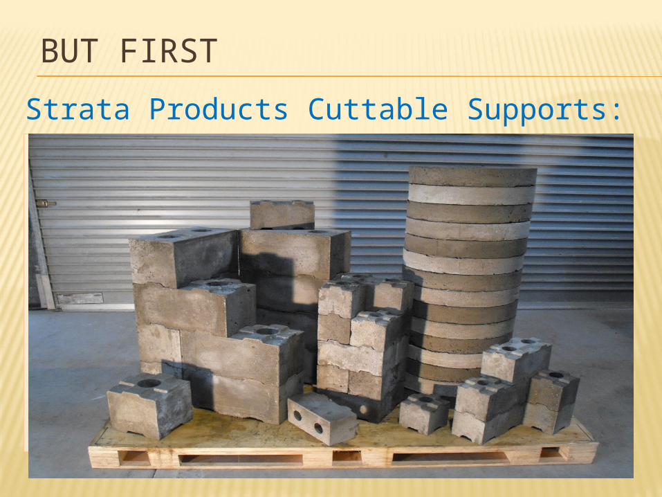
BUT FIRSTStrata Products Cuttable Supports:
0 5 10 15 20 25 30 350
5
10
15
20
25
30
35
40
45
28 day Compression Test 400x200 Link Blocks
Deformation (mm)
Load
(To
nnes
)
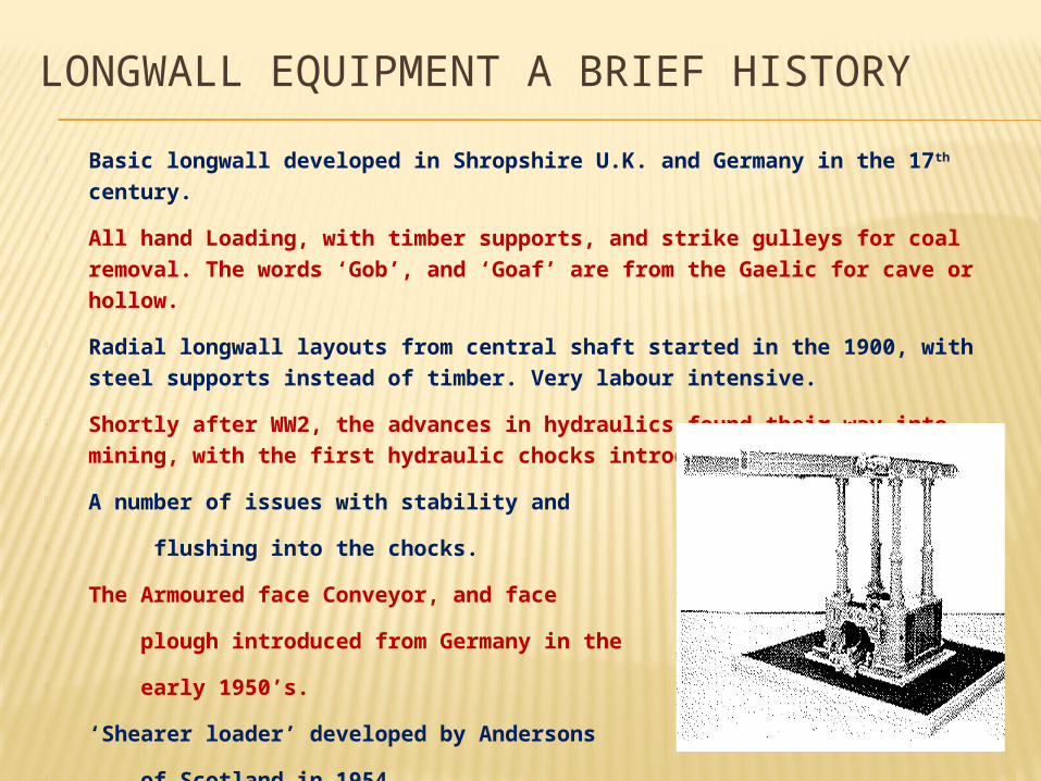
• Basic longwall developed in Shropshire U.K. and Germany in the 17th century.
• All hand Loading, with timber supports, and strike gulleys for coal removal. The words ‘Gob’, and ‘Goaf’ are from the Gaelic for cave or hollow.
• Radial longwall layouts from central shaft started in the 1900, with steel supports instead of timber. Very labour intensive.
• Shortly after WW2, the advances in hydraulics found their way into mining, with the first hydraulic chocks introduced.
• A number of issues with stability and flushing into the chocks.• The Armoured face Conveyor, and face plough introduced from Germany in the early 1950’s. • ‘Shearer loader’ developed by Andersons of Scotland in 1954.
LONGWALL EQUIPMENT A BRIEF HISTORY
HISTORY CONTINUED The ‘Chock shield’ was developed in the late 1960’s with a solid
connection between the top canopy, and the base of the shield, to provide stability, and prevent flushing.
Major changes in the 1980’s were the development of the ‘Lemniscate linkage’, and the change from four to two leg supports.
Support loads increased dramatically, from 250 tonne supports in the early 1970’s, to the current 1475 tonne supports available today.
This development is restricted at present due to space to place the large legs, and limitations on hydraulic pressures and Flow.
Recent major improvements have been in terms of electronic controls, and automation of the longwall equipment.
Face widths have increased from 150m to 350m over the last 15 years
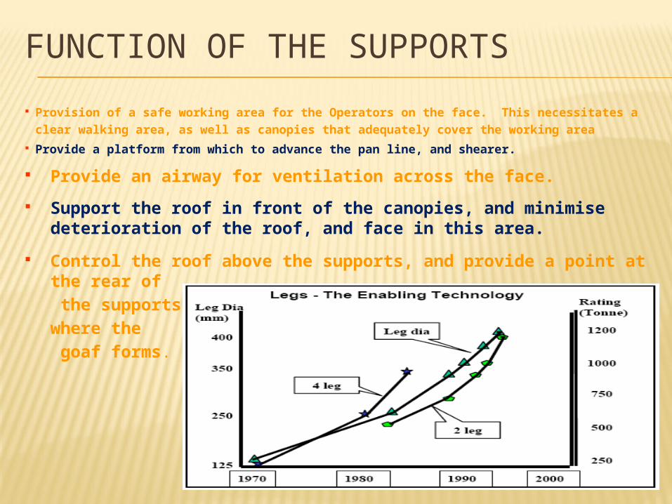
FUNCTION OF THE SUPPORTS Provision of a safe working area for the Operators on the face. This necessitates a
clear walking area, as well as canopies that adequately cover the working area Provide a platform from which to advance the pan line, and shearer. Provide an airway for ventilation across the face. Support the roof in front of the canopies, and minimise
deterioration of the roof, and face in this area. Control the roof above the supports, and provide a point at the
rear of the supports where the goaf forms.
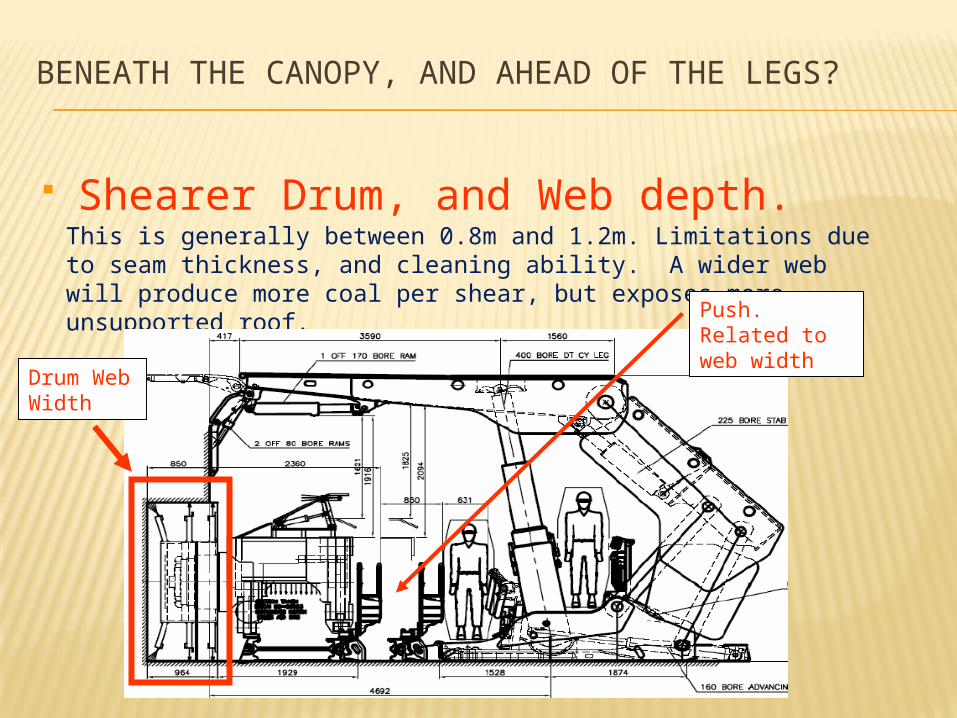
Shearer Drum, and Web depth.This is generally between 0.8m and 1.2m. Limitations due to seam thickness, and cleaning ability. A wider web will produce more coal per shear, but exposes more unsupported roof.
Drum Web Width
Push. Related to web width
BENEATH THE CANOPY, AND AHEAD OF THE LEGS?
Shearer, and Armoured Face Conveyor (A.F.C.)
BENEATH THE CANOPY, AND AHEAD OF THE LEGS?
With the increased production requirements, larger and more powerful shearers and increasingly wider A.F.C.’s are being installed. Is the increase in ‘nameplate’ capacity warranted?Capacity may be driven by ‘Project team’, who require a specific tonnage to make a project ‘work’ . These figures are then ‘discounted’, ultimately requiring a really high capacity coal clearance system to make the figures stack up.
4000 tph x 128hrs x 50% = 256 000 tpw x 48 weeks (LW Move) = 12,288 m tonnesEither we only cut for 31 hours per week, or we definitely don’t use nameplate capacity!!!!
Citect assessment of belt and shearer data indicates that, 80% of nameplate capacity is used for only 2% of production time.Engineering logic suggests that an over rated layout is less likely to be ‘overloaded’, and therefore should be less problematic, and last longer.
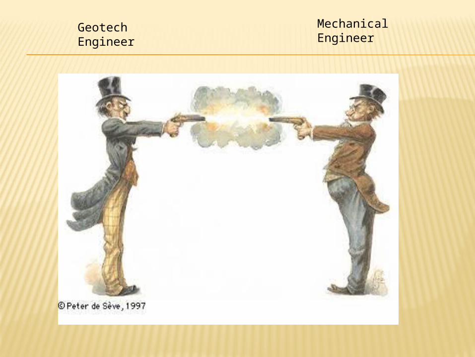
Geotech Engineer
Mechanical Engineer
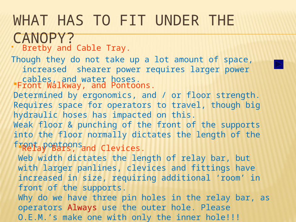
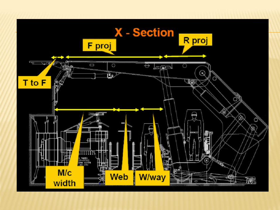
WHAT HAS TO FIT UNDER THE CANOPY? Bretby and Cable Tray.Though they do not take up a lot amount of space, increased
shearer power requires larger power cables, and water hoses.Front Walkway, and Pontoons.Determined by ergonomics, and / or floor strength. Requires space for operators to travel, though big hydraulic hoses has impacted on this. Weak floor & punching of the front of the supports into the floor normally dictates the length of the front pontoons.Relay Bars, and Clevices.Web width dictates the length of relay bar, but with larger panlines, clevices and fittings have increased in size, requiring additional ‘room’ in front of the supports.Why do we have three pin holes in the relay bar, as operators Always use the outer hole. Please O.E.M.’s make one with only the inner hole!!!
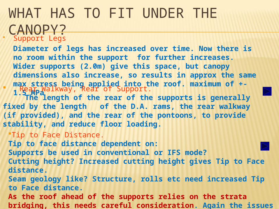
Support Legs Diameter of legs has increased over time. Now there is no room within the support for further increases. Wider supports (2.0m) give this space, but canopy dimensions also increase, so results in approx the same max stress being applied into the roof. maximum of +- 1.5 MPa Rear Walkway, Rear of Support.
The length of the rear of the supports is generally fixed by the length of the D.A. rams, the rear walkway (if provided), and the rear of the pontoons, to provide stability, and reduce floor loading.
Tip to Face Distance.Tip to face distance dependent on:Supports be used in conventional or IFS mode?Cutting height? Increased cutting height gives Tip to Face distance.Seam geology like? Structure, rolls etc need increased Tip to Face distance.As the roof ahead of the supports relies on the strata bridging, this needs careful consideration. Again the issues of Pins in the Relay bars !!!
WHAT HAS TO FIT UNDER THE CANOPY?
Geotech Engineer
Design Personnel
LOADING INTO THE ROOF
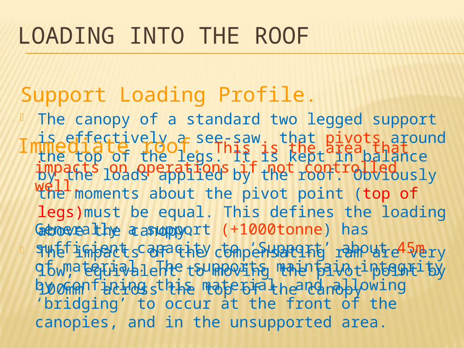
Support Loading Profile. The canopy of a standard two legged support is
effectively a see-saw that pivots around the top of the legs. It is kept in balance by the loads applied by the roof. Obviously the moments about the pivot point (top of legs)must be equal. This defines the loading above the canopy.
The impacts of the compensating ram are very low, equivalent to moving the pivot point by 100mm across the top of the canopy
Immediate roof. This is the area that impacts on operations if not controlled well.
Generally a support (+1000tonne) has sufficient capacity to ‘Support’ about 45m of material. The supports maintain integrity by confining this material, and allowing ‘bridging’ to occur at the front of the canopies, and in the unsupported area.
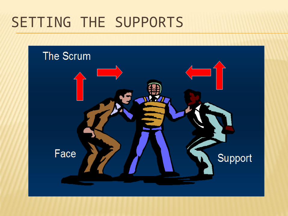
SETTING THE SUPPORTS
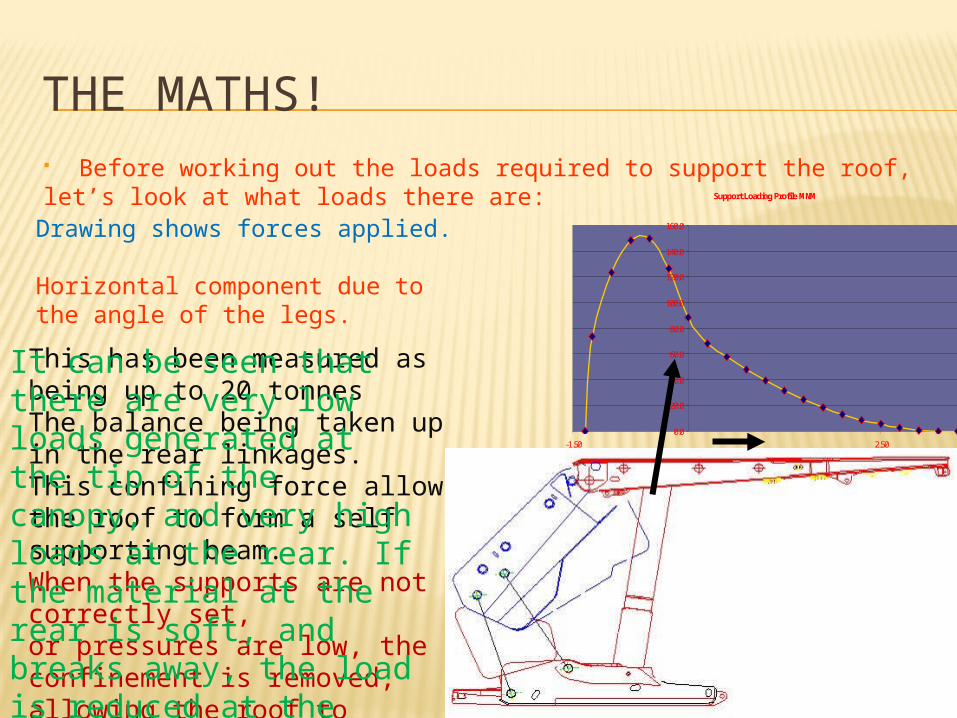
THE MATHS! Before working out the loads required to support the roof, let’s look at what loads there are:
Drawing shows forces applied.
Horizontal component due to the angle of the legs.This has been measured as being up to 20 tonnesThe balance being taken up in the rear linkages.This confining force allows the roof to form a self supporting beam. When the supports are not correctly set, or pressures are low, the confinement is removed, allowing the roof to unravel.
It can be seen that there are very low loads generated at the tip of the canopy, and very high loads at the rear. If the material at the rear is soft, and breaks away, the load is reduced at the rear, and at the same time the front of the canopy.
Support Loading Profile MNM
0.0
20.0
40.0
60.0
80.0
100.0
120.0
140.0
160.0
-1.50 2.50
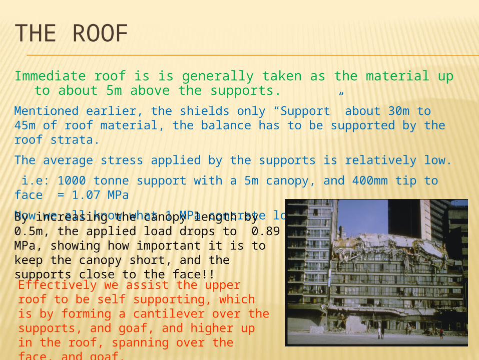
THE ROOFImmediate roof is is generally taken as the material up to about
5m above the supports.Mentioned earlier, the shields only “Support” about 30m to 45m of roof material, the balance has to be supported by the roof strata.The average stress applied by the supports is relatively low. i.e: 1000 tonne support with a 5m canopy, and 400mm tip to face = 1.07 MPaNow we all know what 1 MPa concrete looks like;By increasing the canopy length by 0.5m, the applied load drops to 0.89 MPa, showing how important it is to keep the canopy short, and the supports close to the face!!Effectively we assist the upper roof to be self supporting, which is by forming a cantilever over the supports, and goaf, and higher up in the roof, spanning over the face, and goaf.
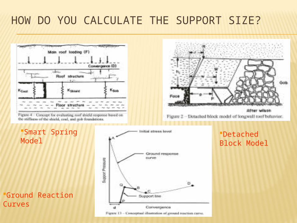
HOW DO YOU CALCULATE THE SUPPORT SIZE?
Smart Spring Model
Detached Block Model
Ground Reaction Curves
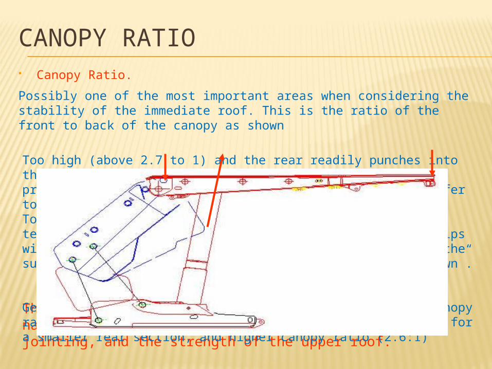
CANOPY RATIO Canopy Ratio.Possibly one of the most important areas when considering the stability of the immediate roof. This is the ratio of the front to back of the canopy as shown
Too high (above 2.7 to 1) and the rear readily punches into the roof, or it is not possible to fully use posi (high pressure) set. In addition, there is very poor load transfer to the tips of the supportsToo low, and the cantilever effect of the upper roof will tend to push down the rear of the supports. Load at the tips will however be improved, and it will be possible to set the supports to full pressure, but the supports may “squat down”.
The choice of canopy ratio is very dependant on the nature of the immediate roof, the direction of jointing, and the strength of the upper roof.Generally the weaker the immediate roof, the lower the canopy ratio (2.3:1), while a stronger immediate roof will allow for a smaller rear section, and higher canopy ratio (2.6:1)
SUPPORT STIFFNESSThere is much discussion regarding the Stiffness of supportsThere are three distinct areas of stiffness:Hydraulic StiffnessConsidered only once the supports have set, the hydraulic stiffness is displacement of the supports due to the compression of the fluid in the legs. This is small; 12mm to 15mm for large supports. (100 bar pressure change decreases the volume of 1 litre of water by 5ml)Mechanical Stiffness.The deformation of the structure, pins, canopy, and expansion of the cylinders. Increases with age, Depending on where measured, between 10 mm and 75mm between zero and set pressure.Setting Stiffness.Crucial in maintaining stability of the roof, is the time taken from cutting the face, to setting the supports. Thereafter the greater the amount of work put into the roof as the roof deforms the better.The hydraulic capacity, clean roof and floor, bank push, and use of Posi set all have a large impact on the ability to rapidly set the supports to the roof. Minimise leaks!!!
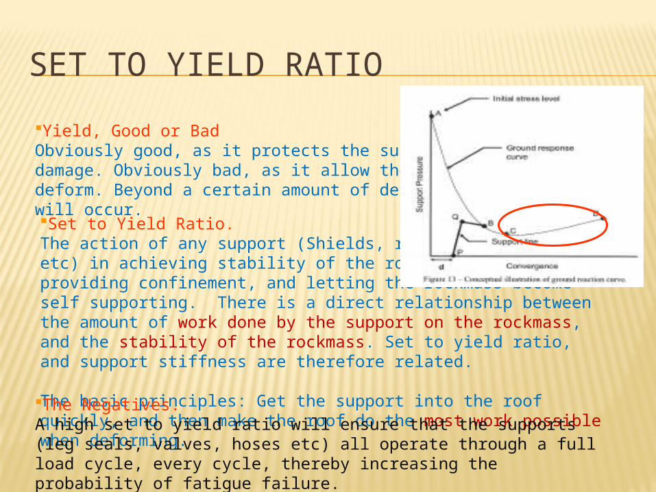
SET TO YIELD RATIOYield, Good or BadObviously good, as it protects the supports from damage. Obviously bad, as it allow the roof strata to deform. Beyond a certain amount of deformation, failure will occur.Set to Yield Ratio.The action of any support (Shields, roof bolts, cables etc) in achieving stability of the rockmass, is in providing confinement, and letting the rockmass become self supporting. There is a direct relationship between the amount of work done by the support on the rockmass, and the stability of the rockmass. Set to yield ratio, and support stiffness are therefore related.
The basic principles: Get the support into the roof quickly, and then make the roof do the most work possible when deforming.The Negatives.A high set to yield ratio will ensure that the supports (leg seals, valves, hoses etc) all operate through a full load cycle, every cycle, thereby increasing the probability of fatigue failure.

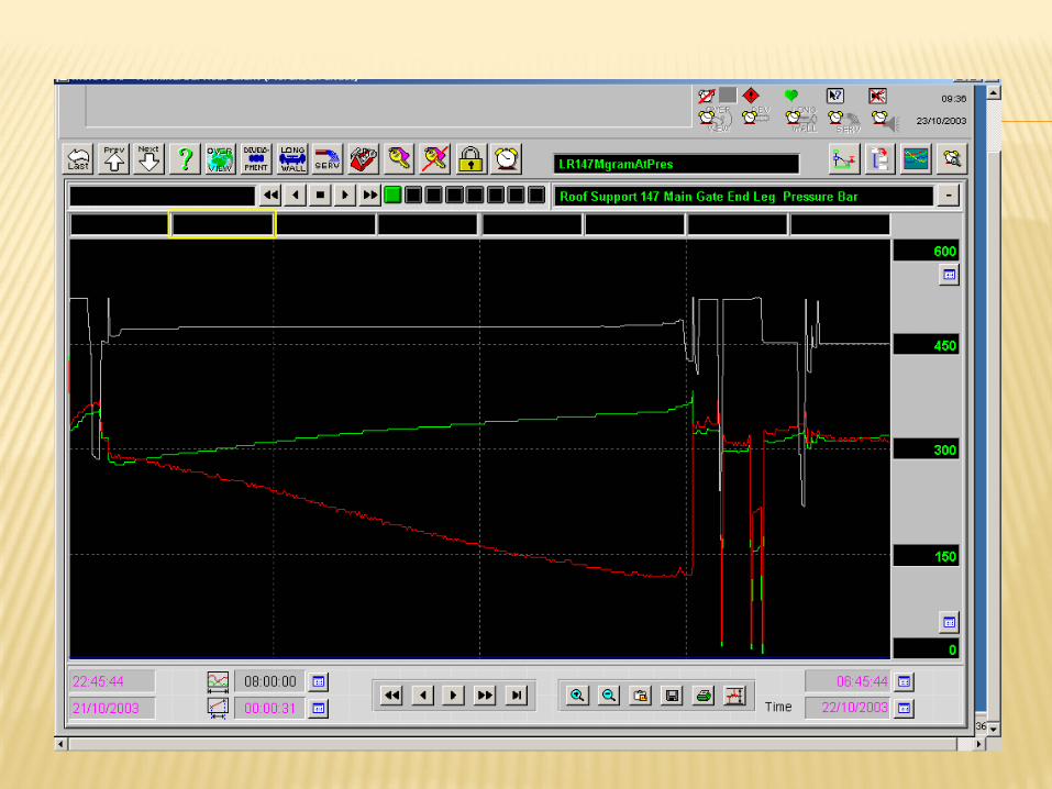
DOES SIZE COUNT?When requesting an OEM for prices, the first question is HOW BIG?With high capacity supports, the biggest impacts to operations are probably the price, the size of components, and the weight of the supports.Geotechnical Perspectives.In an area that has been mined, or has neighbours that have mined a similar seam, the selection of the longwall equipment is easier.A full analysis is still required, but information on roof behaviour, and mining conditions can be added to the equation.Geological mapping from underground operations.Information from Citect, and other monitoring programs:Info they provide:How quickly do the supports set, Leaking legs, how many, and do they impact on supportHow often do the supports go into yield? (S curves)Spacing of yield (weighting?) cycles
SIZE
Geotechnical Perspectives.Greenfield site. The decisions regarding support design, and capacity are driven by:Upper, and lower roof strengths and thicknesses. (spanning ability)Stress environment. (How will the stresses interact with the longwall)Depth (what virgin vertical and horizontal stresses will we have)Longwall width (Sub critical, supercritical, possible spanning)Cutting height (stiffness of face, and supports)Geological structure. (What will we find, and how will it goaf / span)Required Production. (what size do the Engineers want the equipment to be)Budget. (what can we justify to the beancounters.) Quality is remembered long after the price is forgotten!!!Dust and Ventilation (how often do we forget about these issues)
Etc
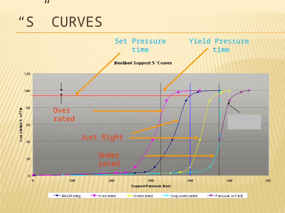
“S” CURVES
Idealised Support 'S' Curves
0
20
40
60
80
100
120
0 100 200 300 400 500 600
Support Pressure (bar)
Cum
ulat
ive
% o
f Tim
e
Ideal Rating Over rated Under rated Very under rated Pressure at Yield
Start Posi Set Posi Set Yield pressure
5 %
This portion not available, due to being in yield
Over rated
Just Right
Under rated
Set Pressuretime
Yield Pressure time
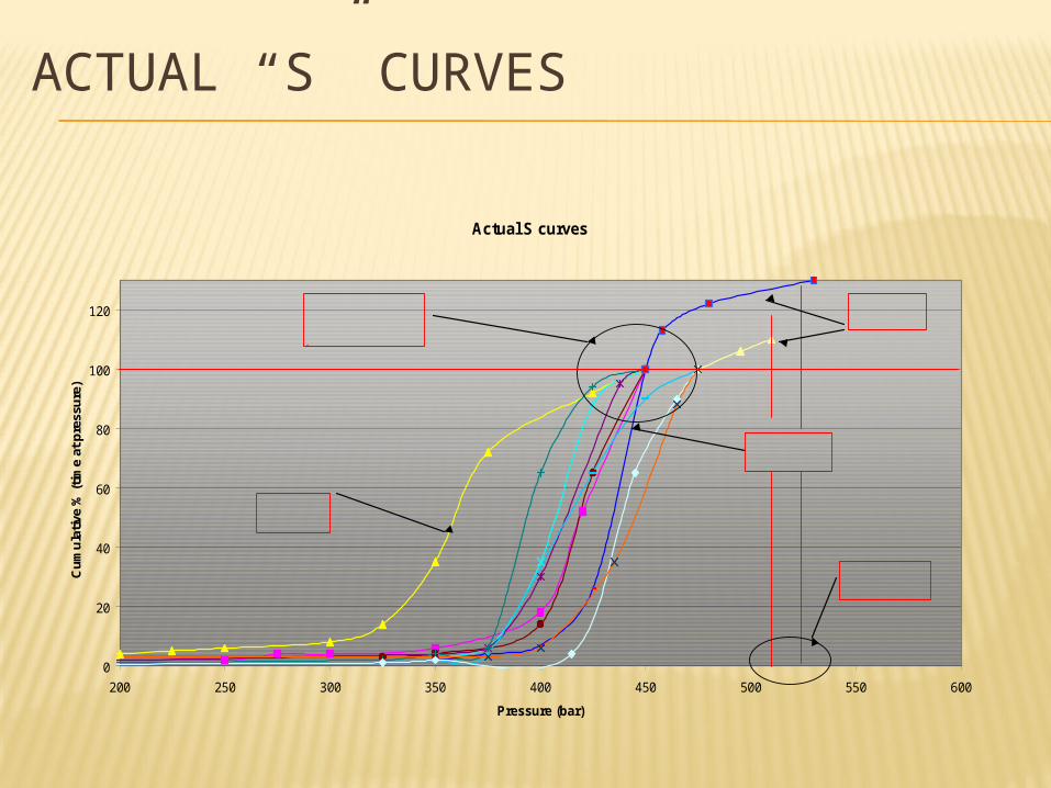
ACTUAL “S” CURVES
Actual S curves
0
20
40
60
80
100
120
200 250 300 350 400 450 500 550 600
Pressure (bar)
Cum
ulat
ive
% (t
ime
at p
ress
ure)
Shallower Longwall
Narrow Longwall
Extrapolated results
Very little curling over in the later panels. 'Under
Effective rating required

Thanks


![Influence of geotechnical factors on gas flow …undergroundcoal.com.au/outburst/pdfs/gas flow[1]-UK.pdf · Influence of geotechnical factors on gas flow experienced in a UK longwall](https://img.pdfslide.net/doc/110x75/5ba30dff09d3f26f6e8d14f8/inuence-of-geotechnical-factors-on-gas-ow-flow1-ukpdf-inuence-of.jpg)