Embed Size (px)
Citation preview
7/30/2019 Low Impact Developement Manual Part B
http://slidepdf.com/reader/full/low-impact-developement-manual-part-b 1/68
DEVELOPMENT BEST MANAGEMENT PRACTICES HANDBOOK LOW IMPACT DEVELOPMENT MANUAL PART B
PLANNING ACTIVITES June 2011 4
TH EDITION

7/30/2019 Low Impact Developement Manual Part B
http://slidepdf.com/reader/full/low-impact-developement-manual-part-b 2/68
THIS PAGE INTENTIONALLY LEFT BLANK

7/30/2019 Low Impact Developement Manual Part B
http://slidepdf.com/reader/full/low-impact-developement-manual-part-b 3/68
This 4th edition is a revision to the 3rd
edition to reflect the newly adopted Low Impact Development
(LID) requirements that take effect May 12, 2012. The handbook was created under the direction of
the City of Los Angeles, who is fully responsible for the content within and a technical committee
comprised of the Departments of Planning, Building and Safety, and Water and Power, the Bureaus of
Street Services and Engineering, and individuals from the development, environmental, and
consultant community.
This Development Best Management Practices Handbook, Part B Planning Activities, 4th edition was
adopted by the City of Los Angeles, Board of Public Works on July 1, 2011 as authorized by Section
64.72 of the Los Angeles Municipal Code approved by Ordinance No. 173494.

7/30/2019 Low Impact Developement Manual Part B
http://slidepdf.com/reader/full/low-impact-developement-manual-part-b 4/68
THIS PAGE INTENTIONALLY LEFT BLANK
7/30/2019 Low Impact Developement Manual Part B
http://slidepdf.com/reader/full/low-impact-developement-manual-part-b 5/68
TABLE OF CONTENTS
SECTION 1: INTRODUCTION.............................................................................................................. 1
1.1 BACKGROUND .......................................... .......................................... ............................................. .........1
1.2 USERS OF THE HANDBOOK..................................... ............................................. .............................. 21.3 HANDBOOK PURPOSE AND SCOPE......................... ................................. ....................................... 2
1.4 LEGAL FRAMEWORK.............................................. .................................................. ............................. 2
1.5 DEVELOPMENT PLANNING PROGRAM.................................................. ....................................... 4
SECTION 2: PROJECT REVIEW AND PERMITTING PROCESS .............................................. 7
2.1 PLAN APPROVAL PROCESS ..................................... ............................................. .............................. 7
2.2 INSPECTION PROCESS.... ....................................... .................................................. .......................... 11
2.3 BMP MAINTENANCE ....................................... ........................................ ........................................... 11
2.4 MUNICIPAL PROJECTS..................... ...................................... .............................................. .............. 12
SECTION 3: STORMWATER MANAGEMENT MEASURES................................................... 13
3.1 LOW IMPACT DEVELOPMENT (LID) PLAN ................................. ............................................. 13
3.2 STANDARD URBAN STORMWATER MITIGATION PLAN (SUSMP).......... ...................... 21
3.3 SITE SPECIFIC MITIGATION.................................. ....................................... ................................... 21
3.4 SOURCE CONTROL MEASURES.................... ...................................... ............................................ 21
SECTION 4: BMP PRIORITIZATION AND SELECTION.......................................................... 24
4.1 PRIORITIZATION OF BMP SELECTION................................................. ...................................... 24
4.2 INFILTRATION FEASIBILITY SCREENING ................................... ............................................. 25
4.3 CAPTURE AND USE FEASIBILITY SCREENING .......................... ............................................. 29
4.4 INFILTRATION BMPS ......................................... ............................................. ................................... 33
4.5 CAPTURE AND USE BMPS ....................................... .............................................. ........................... 44
SECTION 5: OFFSITE MITIGATION MEASURES......................... ............................................. 59
5.1 OFFSITE MITGATION MEASURES............................................. .................................................. .. 59

7/30/2019 Low Impact Developement Manual Part B
http://slidepdf.com/reader/full/low-impact-developement-manual-part-b 6/68
TABLE OF CONTENTS
APPENDICES
Appendix A Development Planning Ordinances
Appendix B CEQA Mitigation Measures
Appendix C Contact List
Appendix D Plan Check Review Forms
Appendix E Small Scale Residential Prescriptive Measures
Appendix F All Other Development Volume Design Calculations
Appendix G Standard Urban Stormwater Mitigation Plan (SUSMP)
Appendix H Site Specific Mitigation Measures
Appendix I LA Department of Building and Safety Stormwater Infiltration Guidelines
Appendix J Upper Los Angeles River Watermaster Requirements
Appendix K County of LA Department of Public Health Policy and Operations Manual
LIST OF TABLES
Table 3.1 Summary of Site Specific Source Control Measure Design Features
Table 4.1 Infiltration Feasibility Screening
Table 4.2 Capture and Use Feasibility Screening
Table 4.3 Landscaped Area Categorization
Table 4.4 Infiltration BMP Design Criteria
Table 4.5 Biofiltration BMP Design Criteria
Table 4.6 Swale Base Width and Length (Per Unit Catchment Area)
Table 4.7 Check Dam Spacing Requirements for Swales
LIST OF FIGURES
Figure 3.1 Small Scale Residential BMP Schematic
Figure 3.2 Requirements for Residential Development of 4 Units or Less
Figure 3.3 Requirements for All Other Developments

7/30/2019 Low Impact Developement Manual Part B
http://slidepdf.com/reader/full/low-impact-developement-manual-part-b 7/68
TABLE OF CONTENTS
ACRONYMS AND ABBREVIATION
ASCE American Society of Civil Engineers
BMP Best Management Practices
BOE Bureau of Engineering
BOS Bureau of Sanitation
CGPL California General Plan Law
CEQA California Environmental Quality Act
CZARA Coastal Zone Act Reauthorization Amendments of 1990
C&A Covenant and Agreement
DCP Los Angeles Department of City Planning
DPW Los Angeles Department of Public Works
EAF Environmental Assessment Form
EIR Environmental Impact Report
EPA
United
States
Environmental
Protection
Agency
ESA Environmentally Sensitive Area
ETWU Estimated Total Water Use
CGPL California General Plan Law
HC Hydrocarbons
LADBS Los Angeles Department of Building and Safety
LID Low Impact Development
MAWA Maximum Applied Water Allowance
MEP Maximum Extent Practicable (statutory standard)
MND Mitigated Negative Declaration
MS4 Municipal Separate Storm Sewer Systems
NPDES National Pollutant Discharge Elimination System
O&G Oil and Grease
O&M Operation and Maintenance
PCIS Plan Check and Inspection System
RGO Retail Gasoline Outlets
RWQCB Los Angeles Regional Water Quality Control Board
SIC Standard Industrial Classification
SOR Stormwater Observation Report
SWRCB State Water Resources Control Board (California)
SUSMP Standard Urban Stormwater Mitigation Plan
ULARA Upper Los Angeles River Area ULARWM Upper Los Angeles River Area Watermaster
WEF Water Environment Federation
WPD Watershed Protection Division
7/30/2019 Low Impact Developement Manual Part B
http://slidepdf.com/reader/full/low-impact-developement-manual-part-b 8/68
Section 1: Introduction |1
CITY OF LOS ANGELES LOW IMPACT DEVELOPMENT BEST MANAGEMENT PRACTICES HANDBOOK
SECTION 1: INTRODUCTION
1.1 BACKGROUND
Urban runoff discharged from municipal storm drain systems has been identified by local, regional, and national research programs as one of the principal causes of water quality impacts
in most urban areas. Urban runoff potentially contains a host of pollutants such as trash and
debris, bacteria and viruses, oil and grease, sediments, nutrients, metals, and toxic chemicals.
These contaminants can adversely affect receiving and coastal waters, associated biota, and
public health. An epidemiological study by the Santa Monica Bay Restoration Project was
conducted to investigate possible health effects of swimming in Santa Monica Bay. Study
results indicated that individuals swimming near flowing storm drain outlets have a greater risk
of developing various symptoms of illnesses compared to those swimming 400 yards away from
the
same
drains.
In
addition,
oil
and
grease
from
parking
lots,
leaking
petroleum
or
other
hydrocarbon products, leachate from storage tanks, pesticides, cleaning solvents, and other
toxic chemicals can contaminate stormwater and be transported downstream into water
bodies and receiving waters. Fertilizer constituents from lawns and golf courses or leaking
septic tanks can cause algal blooms. Disturbances of the soil from construction can allow silt
to wash into storm channels and receiving waters, making them muddy, cloudy, and
inhospitable to natural aquatic organisms. Heavy metals are toxic to aquatic organisms and
many artificial surfaces of the urban environment such as galvanized metal, paint, or preserved
wood containing metals contribute to stormwater pollution as the surfaces corrode, flake,
dissolve, or decay.
Land development and construction activities significantly alter drainage patterns and
contribute pollutants to urban runoff primarily through erosion and removal or change of
existing natural vegetation. When homes, shops, work places, recreational areas, roads,
parking lots, and structures are built, increased flows are discharged into local waterways. As
the amount of impervious surface increases, water that once percolated into the soil now flows
over the land surface. Accordingly, increases in impervious surfaces can increase the frequency
and intensity of stormwater flows through a watershed. Flow from rainstorms and other water
uses wash rapidly across the impervious landscape, scouring the surface of various kinds of
urban pollutants such as automotive fluids, cleaning solvents, toxic or hazardous chemicals,
detergents, sediment, metals, bacteria, pesticides, oil and grease, and food wastes. These
pollutants, unfiltered and unfettered, flow through stormwater infrastructure and ultimately contaminate receiving waters.
7/30/2019 Low Impact Developement Manual Part B
http://slidepdf.com/reader/full/low-impact-developement-manual-part-b 9/68
Section 1: Introduction |2
CITY OF LOS ANGELES LOW IMPACT DEVELOPMENT BEST MANAGEMENT PRACTICES HANDBOOK
1.2 HANDBOOK PURPOSE AND SCOPE
The purpose of this handbook is to assist developers in complying with the requirements of the
Development Planning Program regulations of the City’s Stormwater Program. This handbook
summarizes
the
City’s
project
review
and
permitting
process,
identifies
stormwater
mitigation
measures, and references source and treatment control BMP information. It provides guidance
for individuals involved in new development and redevelopment projects. The target audience
for this handbook includes developers, designers, contractors, homeowners, and City staffs that
are engaged in plan‐checking, permitting, and inspections related to land development
activities. This handbook also contains the necessary forms and worksheets required to be
completed by the developer for approval.
1.3 LEGAL FRAMEWORK
With public concern growing over urban runoff and stormwater pollution, local, state, and
federal agencies have devised plans to control and/or treat stormwater‐related pollution
before it reaches receiving waters.
The Federal Clean Water Act is the principal vehicle for control of stormwater pollution. Under
the Federal Clean Water Act, each municipality throughout the nation is issued a stormwater
permit through the National Pollutant Discharge Elimination System (NPDES) program. The
primary goal of each permit is to stop polluted discharges from entering the storm drain system
and local receiving and coastal waters. In California, the NPDES stormwater permitting
program is administered by the State Water Resources Control Board (SWRCB) through its nine Regional Boards.
On July 5, 1996, the Los Angeles Regional Water Quality Control Board (Regional Board or
RWQCB) adopted Order No. 96‐054‐ the NPDES Stormwater Permit (Permit) for the County of
Los Angeles and cities within (NPDES No. CAS614001). The Permit was issued to Los Angeles
County (Principal Permittee) and 84 cities (Permittees) to reduce pollutants discharged from
their Municipal Separate Storm Sewer Systems (MS4) to the Maximum Extent Practicable (MEP)
statutory standard. On December 13, 2001, the Regional Board adopted a new Permit (Order
No. 01‐182, NPDES Permit No. CAS004001).
The requirement to implement the Permit is based on federal and state statutes, including
Section 402(p) of the Federal Clean Water Act, Section 6217 of the Coastal Zone Act
Reauthorization Amendments (CZARA) of 1990, and the California Water Code. The Federal
Clean Water Act amendments of 1987 established a framework for regulating stormwater
discharges from municipal, industrial, and construction activities under the NPDES program.
The primary objectives of the stormwater program requirements are to:

7/30/2019 Low Impact Developement Manual Part B
http://slidepdf.com/reader/full/low-impact-developement-manual-part-b 10/68
Section 1: Introduction |3
CITY OF LOS ANGELES LOW IMPACT DEVELOPMENT BEST MANAGEMENT PRACTICES HANDBOOK
• Effectively prohibit non‐stormwater discharges, and
• Reduce the discharge of pollutants from stormwater conveyance systems to the MEP
statutory standard.
Based on the Permit issued by the Regional Board, the County and its co‐permittees are
required to develop and implement a number of stormwater management programs designed
to reduce pollutants in stormwater and urban runoff. These programs are the Public
Information and Participation Program, Industrial/Commercial Facilities Program, Illicit
Connections and Illicit Discharges Elimination Program, Development Planning Program,
Development Construction Program, Public Agency Activities Program, and the Monitoring and
Reporting Program.
One of these programs, the Development Planning Program, focuses on preventing pollutants
that could be generated from new development and redevelopment projects from reaching
stormwater conveyance systems and receiving waters. Under this program, the RWQCB
developed requirements for the Standard Urban Stormwater Mitigation Plan (SUSMP) which
requires specific development and redevelopment categories to manage stormwater runoff. In
2002, the City of Los Angeles implemented the SUSMP program requiring all the affected land
development projects to capture or treat stormwater runoff.
A relatively recent stormwater management approach aimed at achieving this goal is the use of
Low Impact Development (LID). Over the past 10 years, LID practices have received increased
attention and implementation, becoming a leading practice for stormwater management. In
recognition of this, recent actions by the RWQCB, SWRCB, and US EPA have prioritized the use
of LID as the preferred approach to stormwater management, including for the purpose of
water quality compliance.
LID is a stormwater management strategy that seeks to mitigate the impacts of increases in
runoff and stormwater pollution as close to its source as possible. LID comprises a set of site
design approaches and Best Management Practices (BMPs) that promote the use of natural
systems for infiltration, evapotranspiration, and use of stormwater. These LID practices can
effectively remove nutrients, bacteria, and metals from stormwater while reducing the volume
and intensity of stormwater flows. With respect to urban development and redevelopment
projects, it can be applied onsite to mimic the site’s predevelopment drainage characteristics.
Through the use of various infiltration techniques, LID is geared towards minimizing surface
area that produces large amounts of runoff and does not allow water to infiltrate into the
ground. Where infiltration is infeasible, the use of bioretention, rain gardens, vegetated
rooftops, and rain barrels that will store, evaporate, detain, and/or treat runoff can be used.
7/30/2019 Low Impact Developement Manual Part B
http://slidepdf.com/reader/full/low-impact-developement-manual-part-b 11/68
Section 1: Introduction |4
CITY OF LOS ANGELES LOW IMPACT DEVELOPMENT BEST MANAGEMENT PRACTICES HANDBOOK
In November 2011, the City adopted the Stormwater LID Ordinance (Ordinance #181899) with
the stated purpose of:
• Requiring the use of LID standards and practices in future developments and
redevelopments
to
encourage
the
beneficial
use
of
rainwater
and
urban
runoff;
• Reducing stormwater/urban runoff while improving water quality;
• Promoting rainwater harvesting;
• Reducing offsite runoff and providing increased groundwater recharge;
• Reducing erosion and hydrologic impacts downstream; and
• Enhancing the recreational and aesthetic values in our communities.
In addition to SUSMP the City institutionalized the use of LID techniques for development and
redevelopment projects. Subsequent to the adoption of the Stormwater LID Ordinance, this
handbook has been amended to require stormwater mitigation for a much larger number of
development projects.
In addition to the SUSMP and LID provisions, other programs dealing with stormwater pollution
include the State of California General Plan Law (CGPL) for Municipalities and the California
Environmental Quality Act (CEQA). The California CGPL and CEQA provide a basis for
municipalities to review and comment on all projects within their jurisdiction. Under the CGPL,
municipalities are required to develop policies and regulations that guide development within
the municipality. Each development project is reviewed for conformance with these policies.
Under CEQA, projects are also subject to review and comment for potential adverse
environmental impacts, including impacts from stormwater discharges.
1.4 DEVELOPMENT PLANNING PROGRAM
The Development Planning Program is, in order of priority, comprised of a LID Plan, and/or a
Standard Urban Stormwater Mitigation Plan (SUSMP), and/or a Site Specific Mitigation Plan.
This handbook provides guidance for compliance with the LID, SUSMP, and Site Specific
Mitigation Plan requirements. Project applicants will be required to incorporate stormwater
mitigation measures into their design plans and submit the plans to the City for review and
approval as described in Section 2.
1.4.1 Low Impact Development Plan
Adopted by the City of Los Angeles on November 14, 2011, the Stormwater LID Ordinance
requires stormwater mitigation for a much larger number of development and redevelopment
projects than was previously required under SUSMP. Prior to the implementation of the LID
7/30/2019 Low Impact Developement Manual Part B
http://slidepdf.com/reader/full/low-impact-developement-manual-part-b 12/68
Section 1: Introduction |5
CITY OF LOS ANGELES LOW IMPACT DEVELOPMENT BEST MANAGEMENT PRACTICES HANDBOOK
Ordinance, the City’s SUSMP program required only specific development and redevelopment
categories to incorporate stormwater BMPs. The Stormwater LID Ordinance has expanded
these categories to include all development and redevelopment projects that create, add, or
replace 500 square feet or more of impervious area.
The Stormwater LID Ordinance applies to all development and redevelopment in the City of Los
Angeles that requires building permits within the City after the ordinance effective date except
for the following:
• A development or redevelopment that only creates, adds, or replaces less than 500
square feet of impervious area;
• A development or redevelopment involving only emergency construction activity
required to immediately protect public health and safety;
• Infrastructure projects within the public right‐of ‐way;
• A development or redevelopment involving only activity related to gas, water, cable, or
electricity services on private property;
• A development or redevelopment involving only re‐striping of permitted parking lots;
• A project involving only exterior movie and television production sets, or facades on
existing developed site.
1.4.2 Standard Urban Stormwater Mitigation Plan (SUSMP)
The
SUSMP
was
adopted
by
the
Regional
Board
on
March
8,
2000
under
Resolution
No.
R‐
00‐
02, and was further amended by the SWRCB on October 5, 2000 under State Water Board
Order WQ 2000‐11. The SUSMP was developed as part of the municipal stormwater program
to address stormwater pollution from new development and redevelopment projects.
The NPDES Permit cites the categories of new development and redevelopment projects that
require stormwater mitigation measures and outlines the necessary BMPs applicable to each
category. The following project categories require a SUSMP:
1. Single‐family hillside residential developments 1
2. Housing developments (including single‐family homes, multi‐family homes,
condominiums, and apartments) of ten or more units
1 Single‐family hillside developments less than one acre excluded from the numerical Structural and Treatment
Control BMP design standard requirements.
7/30/2019 Low Impact Developement Manual Part B
http://slidepdf.com/reader/full/low-impact-developement-manual-part-b 13/68
Section 1: Introduction |6
CITY OF LOS ANGELES LOW IMPACT DEVELOPMENT BEST MANAGEMENT PRACTICES HANDBOOK
3. Industrial/Commercial 2 developments of one acre or more of impervious surface area
4. Automotive service facilities (SIC 5013, 5014, 5541, 7532‐7534, and 7536‐7539)
5. Retail gasoline outlets
6. Restaurants (SIC 5812)
7. Parking lots with 5,000 square feet or more of surface area, including accessory
driveways, or with 25 or more parking spaces
8. Projects located in, adjacent to, or discharging directly to a designated Environmentally
Sensitive Area (ESA)
1.4.3 Site Specific Mitigation Plan
New development and/or redevelopment projects not requiring a LID or SUSMP but which may
potentially have adverse impacts on stormwater quality must incorporate a Site Specific
Mitigation plan to mitigate stormwater pollution. Such projects may have, but are not limited
to, one or more of the following characteristics:
1. Vehicle or equipment fueling areas
2. Vehicle or equipment maintenance areas, including washing and repair
3. Commercial or industrial waste handling or storage
4. Outdoor handling or storage of hazardous materials
5. Outdoor manufacturing areas
6. Outdoor food handling or processing
7. Outdoor animal care, confinement, or slaughter
8. Outdoor horticulture activities
9. Major transportation projects
Projects with one or more of the above characteristics or any project that is subject to the Site
Specific Mitigation requirement will be required to incorporate appropriate stormwater
mitigation measures or apply either LID or SUSMP to satisfy stormwater requirements.
2 Industrial/Commercial Facility: any facility involved and/or used in the production, manufacturing, storage,
transportation, distribution, exchange or sale of goods and/or commodities, and any facility involved and/or used
in providing professional and non‐professional services. This category of facilities includes, but is not limited to,
any facility defined by the Standard Industrial Classifications (SIC).
7/30/2019 Low Impact Developement Manual Part B
http://slidepdf.com/reader/full/low-impact-developement-manual-part-b 14/68
Section 2: Project Review and Permitting Process |7
CITY OF LOS ANGELES LOW IMPACT DEVELOPMENT BEST MANAGEMENT PRACTICES HANDBOOK
SECTION 2: PROJECT REVIEW AND PERMITTING
PROCESS
2.1
PLAN
APPROVAL
PROCESS
The requirement to incorporate stormwater pollution control measures into the design plans of
new development and redevelopment projects in order to mitigate stormwater quality impacts
is implemented through the City’s plan review and approval process. During the review
process, the plans will be reviewed for compliance with the City’s General Plans, zoning
ordinances, and other applicable local ordinances and codes, including stormwater
requirements. Plans and specifications will be reviewed to ensure that the appropriate BMPs
are incorporated to address stormwater pollution prevention goals. The reviewer will also
determine if project designs need to be modified to address stormwater pollution prevention
objectives.
New development and redevelopment projects are mainly processed through DCP and LADBS.
Entitlement approvals are processed by DCP and these projects require discretionary action.
Building/Grading Permit approvals are processed by LADBS.
2.1.1 Department of City Planning Process
The Permit requirements are incorporated into the CEQA process for discretionary projects. The
CGPL and CEQA provide a basis for municipalities to review and comment on all projects within
their jurisdiction. Under the CGPL, municipalities are required to develop policies and
regulations that guide developments within their municipalities. Each development project is
then reviewed for conformance with these policies. Under CEQA, projects are also subject to
review for any adverse impacts the projects may have on the environment, including those
impacts from stormwater discharges. These project types (e.g., zone variances, conditional use
permits, plan amendments, site plan reviews, etc.) are considered discretionary review projects
requiring review by an elected or appointed decision‐making body. Mitigation measures for
stormwater quality impacts (such as stormwater BMPs) will be incorporated into the project
during environmental and project reviews. The project will be reviewed to ensure that required
stormwater BMPs are included. Planning approvals for discretionary projects will not be
granted until stormwater mitigation measures are incorporated into the project plans.
All applications for DCP’s discretionary decisions are required to be accompanied by an
environmental clearance (e.g., Categorical Exemption, Negative Declaration, Mitigated Negative
Declaration, or Environmental Impact Report). When an applicant files an application for a
discretionary project, DCP staff at the public counter will determine whether the project
qualifies for an exemption from CEQA. If the project is not exempt and could possibly have a
significant impact, the applicant files an Environmental Assessment Form (EAF).
7/30/2019 Low Impact Developement Manual Part B
http://slidepdf.com/reader/full/low-impact-developement-manual-part-b 15/68
Section 2: Project Review and Permitting Process |8
CITY OF LOS ANGELES LOW IMPACT DEVELOPMENT BEST MANAGEMENT PRACTICES HANDBOOK
The DCP Environmental Review Section prepares the Initial Study and Checklist. DCP will
indicate if the project will impact water absorption rates, drainage patterns, urban runoff or
other water quality issues. If no significant effect upon the environment is found, a Negative
Declaration
will
be
issued
for
the
project.
If
mitigation
measures
are
needed,
a
Mitigated
Negative Declaration (MND) is issued for the project, or an Environmental Impact Report (EIR) is
required. Stormwater mitigation measures (as shown in Appendix B) will be added to the MND
or the EIR for the decision‐maker to impose as conditions.
The project applicant must incorporate stormwater pollution control measures into the design
plans and submit these plans to the Department of Public Works, Bureau of Sanitation,
Watershed Protection Division (WPD) for review and approval. See Appendix C for contact
information. Upon satisfaction that all stormwater requirements have been met, WPD staff will
stamp the plan approved. Following approval by DCP, building/grading permits are obtained
from LADBS.
2.1.2 Department of Building and Safety Process
Applicants must submit design plans to LADBS personnel for review and approval prior to
issuance of building/grading permits. LADBS personnel determine if the project requires
stormwater mitigation measures and refer applicable projects to WPD for review and approval.
LADBS issues the applicant a “Clearance Worksheet” that identifies all of the outstanding
approvals from City agencies. A building/grading permit will be issued once all corrections have
been completed and clearances are obtained, including for stormwater requirements.
Outlined
below
are
some
guidelines
for
project
applicants
to
follow
in
submitting
design
plans
for review and approval.
Step One - Submit design plans
The project applicant submits the design plans to LADBS. During the plan review process,
LADBS will refer projects needing discretionary action to DCP for additional processing.
Step Two ‐ Define the project category
The plan check engineer will review the design plans and determine if the project is subject to
the LID provisions, falls under any of the SUSMP categories or meets any of the characteristics
identified under Site Specific Mitigation. If the project is subject to LID provisions, falls under
any of the SUSMP categories or meets any of the characteristics identified under Site Specific
Mitigation the plan check engineer will refer the applicant to WPD.
7/30/2019 Low Impact Developement Manual Part B
http://slidepdf.com/reader/full/low-impact-developement-manual-part-b 16/68
Section 2: Project Review and Permitting Process |9
CITY OF LOS ANGELES LOW IMPACT DEVELOPMENT BEST MANAGEMENT PRACTICES HANDBOOK
Step Three – Issue Building and/or Grading Permit
Once all items on the “Clearances Worksheet” have been completed, including stormwater
requirements imposed by WPD, the plan check engineer issues the Building and/or Grading
Permit.
2.1.3 Department of Public Works / Bureau of Sanitation Process
To ensure compliance with all City Codes, it is recommended that the architect, civil engineer,
plumbing engineer, and/or landscape architect coordinate at the early stage of the project
design. Also WPD plan‐checking staff is available for consultation regarding the applicable
requirements based on the project concept.
Step One ‐ Identify appropriate BMPs
Identify, evaluate, and incorporate into the plan documents the appropriate BMPs for the
project categories listed in Section 3.1 (LID), Section 3.2 (SUSMP), or Section 3.3 (Site Specific
Mitigation) of this handbook, whichever is applicable.
To assist the residents in small scale residential development/redevelopment projects (4 units
or less) Appendix E contains prescriptive methods detailing BMPs to be incorporated into the
design plans. The advantage of the prescriptive methods is they were developed as pre‐
approved designs. Use of prescriptive methods for these types of project categories will
dramatically reduce plan preparation and review time.
Approval
for
development
projects
and
building/grading
permits
will
not
be
granted/issued
until appropriate and applicable stormwater BMPs are incorporated into the project design
plans. Also, a plumbing permit from LADBS will be required for certain treatment control BMPs
such as grease traps, sump pumps, and clarifiers. For all projects other than small scale
residential developments (4 units or less), if an infiltration BMP is chosen for treatment control,
a soils report to address the feasibility of infiltration will be required to be submitted with the
plan for review and approval.
Step Two – Submit LID, SUSMP, and/or Site Specific Mitigation plans to WPD for review
For first review, the following is a list of the minimum submittal requirements for Small Scale
Residential Developments
(4
units
or
less):
• One (1) sets of full plans (plot, elevation, utility, mechanical, plumbing, architectural,
and landscape plans).
• Plans must include at least the following:
7/30/2019 Low Impact Developement Manual Part B
http://slidepdf.com/reader/full/low-impact-developement-manual-part-b 17/68
Section 2: Project Review and Permitting Process |10
CITY OF LOS ANGELES LOW IMPACT DEVELOPMENT BEST MANAGEMENT PRACTICES HANDBOOK
• Location, size, and capacity of all BMPs on plans
• Landscaping areas
• Draft Covenant & Agreement (C&A) Form (Appendix D) with an Operation &
Maintenance Plan as discussed in Section 2.3.
For first review, the following is a list of the minimum submittal requirement for all other
projects:
• One (1) set of grading and/or site plans (may need plumbing, architectural, and
landscape plans).
• Plans must be wet‐stamped and signed by an engineer or architect.
• Plans must include, but not limited to, at least the following:
• Location of all BMPs on plans, including elevations and drainage patterns.
• Detailed drawings of all BMPs, including model, size, and capacity
• Stenciling note and/or detail
• Trash enclosure location and details
• Landscaping areas
• Flow calculations identifying flow rate or volume of stormwater runoff that must be
treated (see Appendix F). Submit the manufacturer’s product specifications to verify
that
the
selected
BMP
model
can
adequately
handle
the
design
flow
rate.
• Draft Covenant & Agreement (C&A) Form (Appendix D) with an Operation &
Maintenance Plan as discussed in Section 2.3
Step Three – WPD Approval
WPD plan‐checking staff will review the submitted documents and identify corrections. Once all
LID/SUSMP/Site Specific Mitigation requirements have been met, WPD staff will stamp four (4)
sets of the approved plans, sign the applicant’s clearance worksheet, and clear the project in
the LADBS plan check tracking system, known as the Plan Check and Inspection System (PCIS).
7/30/2019 Low Impact Developement Manual Part B
http://slidepdf.com/reader/full/low-impact-developement-manual-part-b 18/68
Section 2: Project Review and Permitting Process |11
CITY OF LOS ANGELES LOW IMPACT DEVELOPMENT BEST MANAGEMENT PRACTICES HANDBOOK
2.2 INSPECTION PROCESS
To ensure that all stormwater related BMPs are constructed and/or installed in accordance with
the approved LID, SUSMP, Site Specific Mitigation Plan the City requires a Stormwater
Observation
Report
(SOR)
to
be
submitted
to
the
City
prior
to
the
issuance
of
the
Certificate
of
Occupancy.
All projects reviewed and approved will require a SOR which shall be prepared, signed, and
stamped by the engineer of record (for example, a California‐licensed civil engineer, architect,
contractor or qualified professional) responsible for the approved LID/SUSMP/Site Specific
Mitigation Plan, certifying that:
1. He/she is the engineer or architect responsible for the approved LID/SUSMP/Site
Specific Mitigation Plan and
2.
He/she
or
the
designated
staff
under
his/her
responsible
charge
has
performed
the
required site visits at each significant construction stage and at completion to verify that
the BMPs shown on the approved plan have been constructed and installed in
accordance with the approved LID/SUSMP/Site Specific Mitigation Plan.
An original SOR needs to be submitted and not a photocopy. The Certificate of Occupancy will
be issued by LADBS after all required clearances are obtained, including the one by WPD plan‐
checking staff. At that stage the project has been determined, through the normal inspection
process, to be built in accordance with the approved plan, including the construction and/or
installation of appropriate stormwater‐related BMPs and the project has been determined to
comply with all applicable codes, ordinances, and other laws.
2.3 BMP MAINTENANCE
A Covenant and Agreement (C&A) document shall be submitted, along with the design plans
showing the project’s stormwater measures, during the plan review and approval process, and
must be signed by the legal owner or authorized agent of the property. The C&A shall also be
recorded with the County Recorder. The City will withhold the grading and/or building permit
for the development application until this requirement is satisfied. A sample form of the C&A is
provided in Appendix D.
Maintenance is crucial for proper and continuous operation, effectiveness, and efficiency of a
structural or treatment control BMP. The cost of long‐term maintenance should be evaluated
during the BMP selection process. By signing a maintenance form, the legal property owner
affirms he/she will perform regular and long‐term maintenance of all BMPs installed onsite. For
residential properties where the structural or treatment control BMPs are located within a
common area and will be maintained by a homeowner’s association, language regarding the
7/30/2019 Low Impact Developement Manual Part B
http://slidepdf.com/reader/full/low-impact-developement-manual-part-b 19/68
Section 2: Project Review and Permitting Process |12
CITY OF LOS ANGELES LOW IMPACT DEVELOPMENT BEST MANAGEMENT PRACTICES HANDBOOK
responsibility for maintenance must be included in the project’s conditions, covenants and
restrictions (CC&Rs). The C&A is bound to the property and transfers to the new owner with
any subsequent sale of the property. It should be noted that an original copy of the letter of
authority should be submitted for individuals signing the C&A form that are not the property
owners.
Attached
to
the
C&A
will
be
an
Operation
and
Maintenance
(O&M)
Plan
(see
Appendix
D for a sample) describing the BMP operation and maintenance procedures, employee training
program and duties, operating schedule, maintenance frequency, routine service schedule, and
other activities. A maintenance log shall be maintained at the facility to document all of the
activities mentioned above. These documents may be inspected by the City of Los Angeles at
any time and shall be made available to the City upon request.
2.4 MUNICIPAL PROJECTS
Stormwater mitigation measures are required for all projects subject to the LID, SUSMP, or Site
Specific Mitigation Plan. City projects that will be processed through DCP and/or LADBS will be
subject to the review and approval process described in Section 2.1. For other City projects
that do not undergo the plan review and approval process with DCP and/or LADBS, the public
agency must use this handbook to incorporate the required stormwater mitigation measures
into their projects.
Public agency projects other than from the City of Los Angeles, such as State of California,
County of Los Angeles, the Metropolitan Transit Authority that are subject to the SUSMP or Site
Specific Mitigation and require a permit from the City of Los Angeles are required to implement
stormwater mitigation measures. In addition non‐roadway transportation projects that meet
the
thresholds
for
LID/SUSMP
categories
are
also
required
to
implement
stormwater
mitigation
measures. Examples of such projects include the rail lines and stations, airport runways, and
busways. Such projects must incorporate stormwater BMPs into their design plans and
specifications, which must be submitted to WPD for review and approval.
7/30/2019 Low Impact Developement Manual Part B
http://slidepdf.com/reader/full/low-impact-developement-manual-part-b 20/68
Section 3: Stormwater Management Measures |13
CITY OF LOS ANGELES LOW IMPACT DEVELOPMENT BEST MANAGEMENT PRACTICES HANDBOOK
SECTION 3: STORMWATER MANAGEMENT MEASURES
3.1 LOW IMPACT DEVELOPMENT (LID) PLAN
Project applicants for all developments and redevelopments will be required to incorporate
stormwater mitigation measures into their design plans and submit the plans to the City for
review and approval. The design plans will be subjected to a review process as indicated in
Section 2, prior to the issuance of approvals for building and/or grading permits.
Projects that are part of a larger common plan of development involving five units or more will
be subject to the requirements for “All Other Development”, as set forth in Section 3.1.2. This
includes projects that are subject to one common grading permit and projects that have phased
schedules or are intended to be sectioned‐off for sale to individual homeowners.
Project applicants for all developments and redevelopments will also be required incorporate
the following performance measures and practices into their design plans.
Peak Stormwater Runoff Discharge Rates New development and/or redevelopment projects that drain to natural drainage systems in a
small part of the Upper Los Angeles watershed shall control post‐development peak storm
water runoff discharge rates, velocities, and duration (peak flow control) to mimic pre‐
development hydrology and to prevent accelerated stream erosion and to protect stream
habitat. These controls should be consistent with the Hydromodification Control Plan
developed by the County of Los Angeles, Department of Public Works. Conserve
Natural
Areas
Each project site possesses unique topographic, hydrologic and vegetative features, some of
which are more suitable for development than others. Locating development on the least
sensitive portion of a site and conserving naturally vegetated areas can minimize environmental
impacts in general and stormwater runoff impacts in particular.
If applicable and feasible for the given site conditions, the following measures are required and
should be included in the project site layout:
1. Concentrate or cluster improvements on the least‐sensitive portions of the site, while
leaving the remaining land in a natural undisturbed state;
2. Limit clearing and grading of native vegetation at the site to the minimum area needed
to build the home, allow access, and provide fire protection;
3. Maximize trees and other vegetation at the site by planting additional vegetation,
clustering tree areas, and promoting the use of native and/or drought‐tolerant plants;
and
4. Preserve riparian areas and wetlands.
7/30/2019 Low Impact Developement Manual Part B
http://slidepdf.com/reader/full/low-impact-developement-manual-part-b 21/68
Section 3: Stormwater Management Measures |14
CITY OF LOS ANGELES LOW IMPACT DEVELOPMENT BEST MANAGEMENT PRACTICES HANDBOOK
Protect Slopes and Channels Erosion of slopes and channels can be a major source of sediment and associated pollutants,
such as nutrients, if not properly protected and stabilized.
Slope
protection
practices
must
conform
to
design
requirements
or
standards
set
forth
by
local
permitting agency erosion and sediment control standards and design standards. The post‐
construction design criteria described below are intended to enhance and be consistent with
these local standards.
1. Slopes must be protected from erosion by safely conveying runoff from the tops of
slopes.
2. Slopes must be vegetated with first consideration given to native or drought‐tolerant
species.
The following measures should be implemented to provide erosion protection to unlined
receiving streams on the project site. Activities and structures must conform to applicable
permitting requirements, standards and specifications of agencies with jurisdiction (e.g., U.S.
Army Corps of Engineers, California Department of Fish and Game, or RWQCB).
1. Utilize natural drainage systems to the maximum extent practicable, but minimize
runoff discharge to the maximum extent practicable.
2. Stabilize permanent channel crossings.
3. Install energy dissipaters, such as rock riprap, at the outlets of storm drains, culverts,
conduits or channels that discharge into unlined channels.
Provide Storm Drain System Stenciling and Signage Storm drain message markers or placards are required at all storm drain inlets within the
boundary of the project. The marker should be placed in clear sight facing toward anyone
approaching the inlet from either side. All storm drain inlet locations must be identified on the
development site map.
Some local agencies within the City have approved storm drain message placards for use.
Consult local permitting agency stormwater staff to determine specific requirements for
placard types and methods of application.
3.1.1 Environmentally Sensitive Areas (ESAs)
Development and redevelopment projects that are greater than or equal to 1 acre or greater
than or equal to 2,500 square feet and within an ESA, shall comply with the standards and
requirements of Section 3.1.3 ‐ All Other Developments.

7/30/2019 Low Impact Developement Manual Part B
http://slidepdf.com/reader/full/low-impact-developement-manual-part-b 22/68
Section 3: Stormwater Management Measures |15
CITY OF LOS ANGELES LOW IMPACT DEVELOPMENT BEST MANAGEMENT PRACTICES HANDBOOK
3.1.2 SMALL SCALE RESIDENTIAL DEVELOPMENTPROJECTS (4 UNITS AND LESS)
Small scale residential projects include all projects that increase impervious area by more than
500 square feet (i.e., residential development of 4 units or less and all other developments that
are
not
subject
to
Section
1.4.2).
The
majority
of
these
projects
are
not
required
to
complete
formal hydrologic analysis or obtain approval from the Upper Los Angeles River Area (ULARA)
Watermaster. The basic objectives for these projects include reducing a site’s impervious
surfaces, improving a site’s ability to infiltrate stormwater, conserving stormwater runoff for
other on‐site water demand uses, and reducing negative impacts downstream.
REQUIREMENTS:
i. Development or redevelopment less than 1 acre shall implement adequately sized LID
BMP alternatives as defined and listed in Appendix E; or
ii. Development or redevelopment that are one acre or larger, the development shall comply with the standards and requirements of Section 3.1.3 ‐ All Other Developments.
BEST MANAGEMENT PRACTICES (BMPS):
Upon filing an application for a Building Permit with LADBS, a separate plot plan identifying the
LID BMPs that are used (including size) and drainage area tributary to each BMP shall be shown
in accordance with the prescriptive methods.
The following LID BMPs have been established as prescriptive LID improvement features to be
employed on a qualifying small scale project. These BMPs are presented in the form of Fact
Sheets in Appendix E with the intent of providing self ‐contained BMP background context and
sizing requirements to facilitate a permit applicant to follow and comply with the City of Los
Angeles’ Stormwater LID Ordinance. Applicants may choose from one or more of the
prescriptive BMPs to comply with the ordinance.
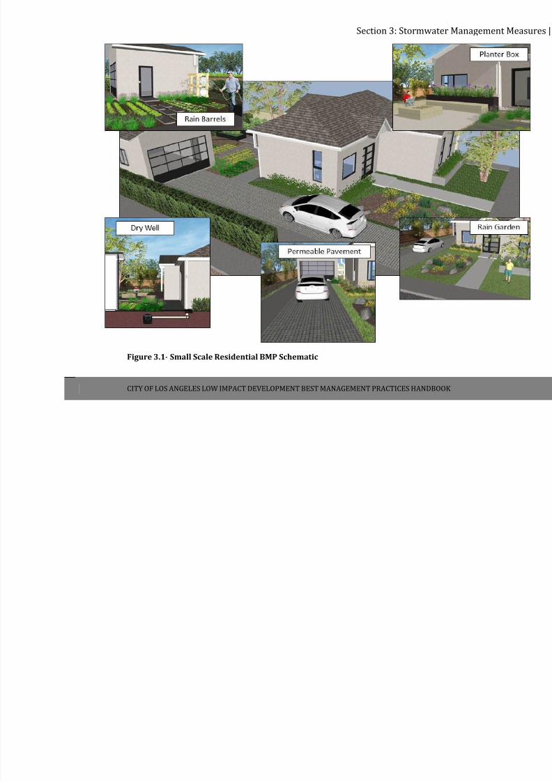
The prescriptive specific small scales BMPs include the following:
1. Rain Barrels & Small Cisterns
2. Permeable Pavements (or Porous Pavement Systems)
3. Planter Boxes
4. Rain Gardens
5. Dry Wells
Figure 3.1 demonstrates the use of all five of these small scale residential BMPs at a residence.
7/30/2019 Low Impact Developement Manual Part B
http://slidepdf.com/reader/full/low-impact-developement-manual-part-b 23/68
Section 3: Stormwater Ma
CITY OF LOS ANGELES LOW IMPACT DEVELOPMENT BEST MANAGEMENT PRACTICES HANDBOOK
Figure 3.1- Small Scale Residential BMP Schematic
7/30/2019 Low Impact Developement Manual Part B
http://slidepdf.com/reader/full/low-impact-developement-manual-part-b 24/68
Section 3: Stormwater Management Measures |17
CITY OF LOS ANGELES LOW IMPACT DEVELOPMENT BEST MANAGEMENT PRACTICES HANDBOOK
3.1.3 ALL OTHER DEVELOPMENTS
Any new development or redevelopment project that does not meet the requirements of
Section 3.1.2 – Small Scale Residential Development Projects, shall comply with this section.
A LID Plan shall be prepared to comply with the following:
1. Stormwater runoff will be infiltrated, evapotranspired, captured and used, and/or treated
through high removal efficiency Best Management Practices onsite, through stormwater
management techniques as identified in Section 4.1. The onsite stormwater management
techniques must be properly sized, at a minimum, to infiltrate, evapotranspire, store for
use, and/or treat through a high removal efficiency biofiltration/biotreatment system,
without any stormwater runoff leaving the site to the maximum extent feasible, for at least
the volume of water produced by the water quality design storm event that results from:
i. The 85th percentile 24‐hour runoff event determined as the maximized capture
stormwater volume for the area using a 48 to 72‐hour drawdown time, from the
formula recommended in Urban Runoff Quality Management, WEF Manual of Practice
No. 23/ASCE Manual of Practice No. 87, (1998); or
ii. The volume of annual runoff based on unit basin storage water quality volume, to
achieve 80 percent or more volume treatment by the method recommended in the
California Stormwater Best Management Practices Handbook – Industrial/Commercial,
(2003); or
iii. The volume of runoff produced from a 0.75 inch storm event.
2. Pollutants shall be prevented from leaving the development site for a water quality design
storm event as defined above unless it has been treated through an onsite high removal
efficiency biofiltration/biotreatment system.
3. Hydromodification impacts shall be minimized to natural drainage systems.
REQUIREMENTS:
All
other
developments
(residential
developments
of
5
units
or
more
and
nonresidential
developments) shall adhere to the following requirements:
1. For new development or where redevelopment results in an alteration of at least fifty
percent or more of the impervious surfaces of an existing developed site, the entire site
shall comply with the standards and requirements of Section 3.1.3; or

7/30/2019 Low Impact Developement Manual Part B
http://slidepdf.com/reader/full/low-impact-developement-manual-part-b 25/68
Section 3: Stormwater Management Measures |18
CITY OF LOS ANGELES LOW IMPACT DEVELOPMENT BEST MANAGEMENT PRACTICES HANDBOOK
2. Where the redevelopment results in an alteration of less than fifty percent of the
impervious surfaces of an existing developed site, only such incremental development shall
comply with the standards and requirements of Section 3.1.3.
If
partial
or
complete
onsite
compliance
of
any
type
is
technically
infeasible,
the
project
Site
and
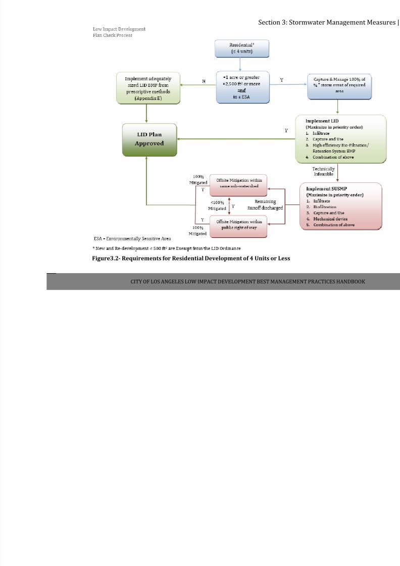
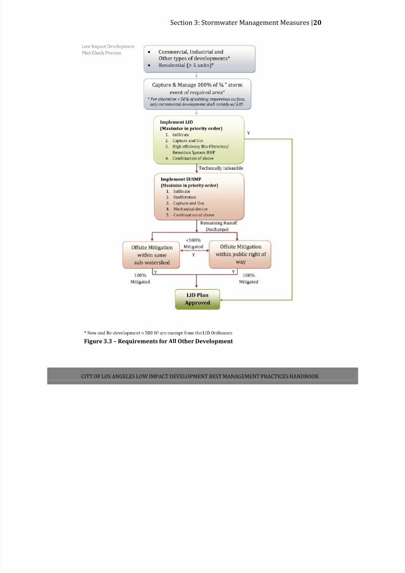
LID Plan shall be required to comply with, at a minimum, all applicable SUSMP requirements
(Appendix G) in order to maximize onsite compliance. Any remaining runoff that cannot feasibly
be managed onsite must be mitigated under the Offsite Mitigation Option. Figure 3.2 is a
schematic which depicts the design requirements for small scale residential projects, while
Figure 3.3 depicts the design requirements for all other developments.
7/30/2019 Low Impact Developement Manual Part B
http://slidepdf.com/reader/full/low-impact-developement-manual-part-b 26/68
Section 3: Stormwater Ma
CITY OF LOS ANGELES LOW IMPACT DEVELOPMENT BEST MANAGEMENT PRACTICES
Figure3.2- Requirements for Residential Development of 4 Units or Less
7/30/2019 Low Impact Developement Manual Part B
http://slidepdf.com/reader/full/low-impact-developement-manual-part-b 27/68
Section 3: Stormwater Management Measures |20
CITY OF LOS ANGELES LOW IMPACT DEVELOPMENT BEST MANAGEMENT PRACTICES HANDBOOK
Figure 3.3 – Requirements for All Other Development
7/30/2019 Low Impact Developement Manual Part B
http://slidepdf.com/reader/full/low-impact-developement-manual-part-b 28/68
Section 3: Stormwater Management Measures |21
CITY OF LOS ANGELES LOW IMPACT DEVELOPMENT BEST MANAGEMENT PRACTICES HANDBOOK
3.2 STANDARD URBAN STORMWATER MITIGATION PLAN (SUSMP)
Any project that cannot comply with the LID requirements in Section 3.1 shall be required to
comply with, at a minimum, all applicable SUSMP requirements (Appendix G) in order to
maximize onsite compliance.
Project applicants will be required to incorporate stormwater mitigation measures into their
design plans and submit the plans to the City for review and approval. The design plans will be
subjected to a review process as indicated in Section 2, prior to the issuance of approvals for
building and/or grading permits.
3.3 SITE SPECIFIC MITIGATION
Site Specific project applicants will be required to submit to the City a design plan that
incorporates appropriate stormwater mitigation measures and details the source and
treatment
control
BMPs,
and
must
also
submit
the
O&M
plan
for
the
treatment
control
BMPs.
All maintenance agreements should refer the Covenant and Agreement forms in Appendix D.
The design plans will be subject to the review and approval process described in Section 2, prior
to the issuance of building or grading permits.
3.4 SOURCE CONTROL MEASURES
Source control measures are low‐technology practices designed to prevent pollutants from
contacting stormwater runoff or to prevent discharge of contaminated runoff to the storm
drainage system. This section addresses site‐specific source control measures consisting of
specific design features or elements. These control measures have been developed for specific
types of sites or activities that have been identified as potential significant sources of pollutants
in stormwater. Each of the measures specified in this section should be implemented in
conjunction with any other operational source control measure such as good housekeeping,
and employee training to optimize pollution prevention.
The measures addressed in this section apply to both stormwater and non‐stormwater
discharges. Non‐stormwater discharges are the discharge of any substance, such as process
wastewater, to the storm drainage system or water body that is not composed entirely of
stormwater. Stormwater that is mixed or commingled with other non‐stormwater flows is
considered non‐stormwater. Discharges of stormwater and non‐stormwater to the storm
drainage
system
or
a
water
body
may
be
subject
to
local,
state,
or
federal
permitting
prior
to
discharge. The appropriate agency should be contacted prior to any discharge. Discuss the
matter with the stormwater staff if you are uncertain as to which agency should be contacted.
Some of the measures presented in this section require connection to the sanitary sewer
system. Connection and discharge to the sanitary sewer system without prior approval or
obtaining the required permits is prohibited. Contact the WPD staff to obtain information

7/30/2019 Low Impact Developement Manual Part B
http://slidepdf.com/reader/full/low-impact-developement-manual-part-b 29/68
Section 3: Stormwater Management Measures |22
CITY OF LOS ANGELES LOW IMPACT DEVELOPMENT BEST MANAGEMENT PRACTICES HANDBOOK
regarding obtaining sanitary sewer permits from the appropriate City office. Discharges of
certain types of flows to the sanitary sewer system may be cost prohibitive and may not be
allowed. The designer is urged to contact the appropriate City offices prior to completing site
and equipment design of the facility.
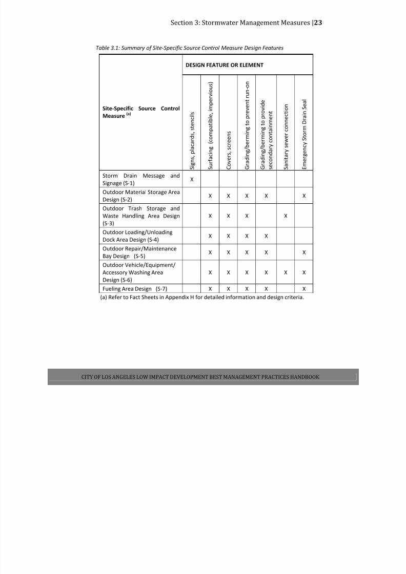
Site‐specific source control measures and associated design features specified for various sites
and activities are summarized in Table 3.1. Fact Sheets are presented in Appendix H for each
source control measure. These sheets include design criteria established by the City to ensure
effective implementation of the required measures. Finally the CEQA Mitigation Measures
listed in Appendix B includes a number of additional source control measures that should be
implemented.
The source control measures and the site specific requirements that are discussed in this
section should be incorporated in the design plans when appropriate. The C&A should also
make a reference to any long‐term operational plans such as a Stormwater Pollution Prevention
Plan (SWPPP) to commit the facility to these measures.
7/30/2019 Low Impact Developement Manual Part B
http://slidepdf.com/reader/full/low-impact-developement-manual-part-b 30/68
Section 3: Stormwater Management Measures |23
CITY OF LOS ANGELES LOW IMPACT DEVELOPMENT BEST MANAGEMENT PRACTICES HANDBOOK
Table 3.1: Summary of Site‐Specific Source Control Measure Design Features
DESIGN FEATURE OR ELEMENT
Site‐Specific Source Control
Measure
(a)
S i g n s ,
p l a c a r d s , s t e n c i l s
S u r f a c
i n g
( c o m p a t i b l e , i m p e r v i o u s )
C o v e r s , s c r e e n s
G r a d i n
g / b e r m i n g t o p r e v e n t r u n
‐ o n
G r a d i n
g / b e r m i n g t o p r o v i d e
s e c o n d a r y c o n t a i n m e n t
S a n i t a r y s e w e r c o n n e c t i o n
E m e r g
e n c y S t o r m
D r a i n S e a l
Storm Drain Message and
Signage (S‐1) X
Outdoor Material Storage Area
Design (S‐2) X X X X X
Outdoor Trash Storage and
Waste Handling Area Design
(S‐3)
X X X X
Outdoor Loading/Unloading
Dock Area Design (S‐4) X X X X
Outdoor Repair/Maintenance
Bay Design (S‐5) X X X X X
Outdoor Vehicle/Equipment/
Accessory Washing Area
Design (S‐6)
X X X X X X
Fueling Area Design (S‐7) X X X X X
(a) Refer to Fact Sheets in Appendix H for detailed information and design criteria.
7/30/2019 Low Impact Developement Manual Part B
http://slidepdf.com/reader/full/low-impact-developement-manual-part-b 31/68
Section 4: BMP Prioritization and Selection|24
CITY OF LOS ANGELES LOW IMPACT DEVELOPMENT BEST MANAGEMENT PRACTICES HANDBOOK
SECTION 4: BMP PRIORITIZATION AND SELECTION
4.1 PRIORITIZATION OF BMP SELECTION
BMPs shall be designed to manage and capture stormwater runoff. Infiltration systems are the
first priority type of BMP improvements as they provide for percolation and infiltration of the
stormwater into the ground, which not only reduces the volume of stormwater runoff entering
the MS4, but in some cases, can contribute to groundwater recharge. If stormwater infiltration
is not possible based on one or more of the project site conditions listed below, the developer
shall utilize the next priority BMP.
The order of priority specified below shall apply to all projects categorized as “all other
developments” in accordance with Section 3.1.3. Each type of BMP shall be implemented to the
maximum extent feasible when determining the appropriate BMPs for a project.
1.
Infiltration Systems
2. Stormwater Capture and Use
3. High Efficiency Biofiltration/Bioretention Systems
4. Combination of Any of the Above
For purposes of compliance with the LID requirements, and without changing the priority order
of design preferences as mentioned in this section, all runoff from the water quality design
storm event, as determined in Section 3.1.3 above, that has been treated through an onsite
high removal efficiency biofiltration system shall be credited as equivalent to 100% infiltration
regardless of the runoff leaving the site from the onsite high removal efficiency biofiltration
system and that runoff volume shall not be subject to the offsite mitigation requirements.
If partial or complete onsite compliance of any type is technically infeasible, the project Site and
LID Plan shall be required to comply with, at a minimum, all applicable SUSMP requirements in
order to maximize onsite compliance. Under this option a mechanical / hydrodynamic unit may
be used. Any remaining runoff that cannot feasibly be managed onsite must be mitigated under
the offsite mitigation option.
7/30/2019 Low Impact Developement Manual Part B
http://slidepdf.com/reader/full/low-impact-developement-manual-part-b 32/68
Section 4: BMP Prioritization and Selection|25
CITY OF LOS ANGELES LOW IMPACT DEVELOPMENT BEST MANAGEMENT PRACTICES HANDBOOK
4.2 INFILTRATION FEASIBILITY SCREENING
The implementation of infiltration BMPs may be deemed infeasible at a project site due to
existing site conditions. To assist in the determination of compliance feasibility, a categorical
screening of specific site information shall be carried out to assess site conditions.
The first category of screening shall consist of specific site conditions which, if present at the
site, would deem the specified BMP‐type “feasible”. The second category of screening shall
consist of specific site conditions which, if present at the site, would deem the BMP‐type
“potentially feasible”. Project locations passing this screening category may still be able to
utilize the screened compliance measure, though the implementation of such a measure may
require supplementary actions. The third category of screening shall consist of site conditions
which, if present at the site, would deem a specified BMP‐type “infeasible”. This type of
screening can generally be carried out in the pre‐planning stage of a project. These categorical
screenings must be verified by a site‐specific geotechnical investigation report and/or
hydrologic analysis conducted and certified by a State of California registered professional
geotechnical engineer or geologist and approved by LADBS.
To assist in the determination of site feasibility for infiltration BMPs, Table 4.1 has been
created.
7/30/2019 Low Impact Developement Manual Part B
http://slidepdf.com/reader/full/low-impact-developement-manual-part-b 33/68
7/30/2019 Low Impact Developement Manual Part B
http://slidepdf.com/reader/full/low-impact-developement-manual-part-b 34/68
Section 4: BMP Prioritization and Selection |27
CITY OF LOS ANGELES LOW IMPACT DEVELOPMENT BEST MANAGEMENT PRACTICES HANDBOOK
Assessing Site Infiltration Feasibility
Assessing a site’s potential for implementation of Low Impact Development Best Management
Practices (LID BMPs) and infiltration BMPs requires both the review of existing information and
the collection of site‐specific measurements. Available information regarding site layout and
slope, soil type, geotechnical conditions, and local groundwater conditions should be reviewed as discussed below. In addition, soil and infiltration testing is required to be conducted to
determine if stormwater infiltration is feasible and to determine the appropriate design
parameters for the infiltration BMP.
Geotechnical Considerations and Report Requirements:
As determined by the City of Los Angeles, Department of Building and Safety, Grading Division,
a geotechnical report will be required for projects that will incorporate infiltration as part of the
drainage system. Geotechnical reports shall be signed by a professional Geotechnical or Civil
Engineer licensed in the State of California and/or a Certified Engineering Geologist.
Refer to Building & Safety information bulletin, “Guidelines for Stormwater Infiltration” for
additional information, Appendix I.
http://ladbs.org/LADBSWeb/LADBS_Forms/InformationBulletins/IB‐P‐BC2008‐118StormwaterInfiltn.pdf
Site Conditions
Slope:
The site’s topography should be assessed to evaluate surface drainage, topographic high and
low points, and to identify the presence of steep slopes that qualify as hillside locations, all of which have an impact on what type of infiltration BMPs will be most beneficial for a given
project site. Stormwater infiltration is more effective on level or gently sloping sites. On
hillsides, infiltrated runoff may seep a short distance down slope, which could cause slope
instability depending on the soil or geologic conditions, or result in nuisance seepage. Figure E‐1
in Appendix E provides general guidance of the City with slopes greater than 15%.
Soil Type and Geology:
The site’s soil types and geologic conditions should be determined to evaluate the site’s ability
to infiltrate stormwater and to identify suitable, as well as unsuitable locations for locating
infiltration‐based BMPs.
In addition, available geologic or geotechnical reports on local geology should be reviewed to
identify relevant features such as depth to bedrock, rock type, lithology, faults, and
hydrostratigraphic or confining units. These geologic investigations may also identify shallow

7/30/2019 Low Impact Developement Manual Part B
http://slidepdf.com/reader/full/low-impact-developement-manual-part-b 35/68
Section 4: BMP Prioritization and Selection |28
CITY OF LOS ANGELES LOW IMPACT DEVELOPMENT BEST MANAGEMENT PRACTICES HANDBOOK
water tables and past groundwater issues that are important for BMP design (see below).
Figure E‐5 in Appendix E provides general guidance identifying parts of the City that have well‐
draining soil conditions.
Groundwater Considerations:
The depth to groundwater beneath the project during the wet season may preclude infiltration.
A minimum of five feet of separation to the seasonal (December through April) high ground
water level and mounded groundwater level is required. For projects located in the Upper Los
Angeles River Area, ten feet of separation is required.
Infiltration on sites with contaminated soils or groundwater that could be mobilized or
exacerbated by infiltration is not allowed, unless a site‐specific analysis determines the
infiltration would be beneficial. A site‐specific analysis may be conducted where groundwater
pollutant mobilization is a concern to allow for infiltration‐based BMPs. Areas with known
groundwater impacts include sites listed by the RWQCB’s Leaking Underground Storage Tanks
(LUST) program and Site Cleanup Program (SCP). The California State Water Resources Control
Board maintains a database of registered contaminated sites through their ‘Geotracker’
Program. Registered contaminated sites can be identified in the project vicinity when the site
address is typed into the “map cleanup sites” field. Mobilization of groundwater contaminants
may also be of concern where contamination from natural sources is prevalent (e.g., marine
sediments, selenium rich groundwater, to the extent that data is available). Figure E‐3 in
Appendix E provides general guidance identifying parts of the City that may be in areas of
concern.
Upper Los Angeles River Watermaster Requirements:
Infiltration projects located in the Upper Los Angeles River Area (ULARA) must comply with the
requirements of the ULARA Watermaster. See Appendix J for requirements and approval
process. Boundaries of the ULARA are shown in Appendix J.
Managing Offsite Drainage:
Locations and sources of offsite run‐on to the site must be identified early in the design
process. Offsite drainage must be considered when determining appropriate BMPs for the site
so that the drainage can be managed. By identifying the locations and sources of offsite
drainage, the volume of water running onto the site may be estimated and factored into the
siting and sizing of onsite BMPs. Vegetated swales or storm drains may be used to intercept,
divert, and convey offsite drainage through or around a site to prevent flooding or erosion that
might otherwise occur.
7/30/2019 Low Impact Developement Manual Part B
http://slidepdf.com/reader/full/low-impact-developement-manual-part-b 36/68
Section 4: BMP Prioritization and Selection |29
CITY OF LOS ANGELES LOW IMPACT DEVELOPMENT BEST MANAGEMENT PRACTICES HANDBOOK
4.3 CAPTURE AND USE FEASIBILITY SCREENING
Capture and use, commonly referred to as rainwater harvesting, collects and stores stormwater
for later use, thereby reducing the quantity of stormwater runoff. Partial capture and use can
also be achieved as part of a treatment train by directing the overflow to a bioretention system
to provide additional volume reduction and water quality treatment in instances where the
quantity of runoff from a storm event exceeds the volume of the collection tank.
In the City of Los Angeles, the use of collected stormwater will primarily be limited to irrigation
of landscaped surfaces. However, as new guidelines and guidance becomes available the
potential for other uses of collected stormwater will be considered. Capture and use BMPs that
are designed with the intent to use captured stormwater for indoor or consumptive purposes
will be reviewed on a case‐by‐case basis to ensure that all treatment, plumbing, and Building
and Safety codes are met.
At a minimum, capture and use BMPs must be designed and maintained to ensure adequate
capacity is available to capture the stormwater quality design volume within 3 days of a storm
event that is forecasted to have a 50% or grater probability of providing precipitation.
Precipitation forecast information must be obtained from the National Weather Service
Forecast Office (e.g. by entering the zip code of the developments location at
http://www.srh.noaa.gov/forecast). BMPs sized to capture only the runoff produced from the
0.75 inch storm event, or BMPs designed to capture less than this volume if being used in
conjunction with other BMPs, must therefore drawdown their entire captured volume within 3
days of a storm event. Capture and use BMPs designed for storm events larger than 0.75 inches
are not required to disperse their entire captured volume within 3 days of capture; rather, the
requirement mandates that enough water be dispersed from the BMP to ensure that adequate
capacity is available to capture the next storm event up to 0.75 inches.
In instances where the quantity of runoff from the 0.75 inch storm event exceeds the volume of
the collection tank, partial capture and use can also be achieved as part of a treatment train by
directing the overflow to stable vegetated areas where erosion or suspension of sediment is not
a factor or through a high flow biotreatment BMP to provide additional volume reduction and
water quality treatment. Overflow from the tank into the storm drain system is not allowed.
The implementation of capture and use BMPs may be deemed infeasible at a project site due to
existing site conditions. To assist in the determination of compliance feasibility, a categorical
screening of specific site information shall be carried out to assess site conditions. This
screening approach follows the same general guidelines as those designed for the infiltration
feasibility screening. Table 4.2 has been created to help determine site feasibility for capture
and use BMPs.
7/30/2019 Low Impact Developement Manual Part B
http://slidepdf.com/reader/full/low-impact-developement-manual-part-b 37/68

7/30/2019 Low Impact Developement Manual Part B
http://slidepdf.com/reader/full/low-impact-developement-manual-part-b 38/68
Section 4: BMP Prioritization and Selection |31
DEVELOPMENT BEST MANAGEMENT PRACTICES HANDBOOK – PART B: PLANNING ACTIVITIES, 4 TH ED.
Table 4.3 has been created to help determine site feasibility for capture and use BMPs based on
the local infiltration rate as well and the percent of the project that is landscaped. The table is
to be used in conjunction with Table 4.2 to determine site feasibility.
Table 4.3: Landscaped Area Categorization Percent of Project that is Landscaped
Local Infiltration Rate 0‐5% 5‐10% 10‐20% 20‐30% 30‐50% >50%
0.3 ‐ 0.5 in/hr 2 2 2 1 1 1
0.2 ‐ 0.3 in/hr 3 2 2 2 1 1
0.1 ‐ 0.2 in/hr 3 3 2 2 2 1
0 ‐ 0.1 in/hr 3 3 3 2 2 2
Assessing Site Capture and Use Feasibility
As with infiltration BMPs, assessing a site’s potential for implementation of capture and use
BMPs requires both the review of existing information and the collection of site‐specific
measurements. Available information regarding the site’s landscaped area should be reviewed
as discussed below. In addition, human health concerns should be prioritized, particularly with
regards to vector control issues arising from the addition of standing water on site.
Landscaped Area Assessment
For capture and use BMPS, captured rainfall is stored during rain events and used for irrigation
purposes at a later time, thereby offsetting potable water demand and reducing pollutant
loading to the storm drain system. Therefore, sufficient landscaped area with appropriate
water demand is needed for the captured runoff to be directed to. A properly sized cistern
should be able to contain the runoff generated from the design storm event and discharge that
water for irrigation use within a specified drawdown time.
In the City of Los Angeles, cisterns will primarily be sized to capture the runoff generated from
the 0.75 inch storm while meeting the drawdown time requirement. A site’s landscaped area
must therefore be able to retain this volume of water within the appropriate drawdown time.
Depending on the type of irrigation application that is desirable at a site, two different methods
exist to determine if a site has adequate landscaped cover for capture and use feasibility:
1. For sites with sufficient agronomic demand to meet or exceed the captured supply of
stormwater within the drawdown time, Category 1 Feasibility may apply. Agronomic
demand must be calculated and reported by a professional landscape architect or
qualified professional.
2. For sites with sufficient landscaped area and dispersal capacity (i.e. ability to receive
irrigation water without generating runoff) to meet or exceed the captured supply of
stormwater within the drawdown time, Category 2 Feasibility may apply. The dispersal
capacity can be assumed to be equal to the infiltration capacity of the site soil for
7/30/2019 Low Impact Developement Manual Part B
http://slidepdf.com/reader/full/low-impact-developement-manual-part-b 39/68
Section 4: BMP Prioritization and Selection |32
DEVELOPMENT BEST MANAGEMENT PRACTICES HANDBOOK – PART B: PLANNING ACTIVITIES, 4 TH ED.
simplicity. The infiltration rate must be calculated and reported by a professional
landscape architect, civil engineer, geotechnical engineer, or geologist.
The above criteria must be assessed assuming that no irrigation occurs within the first 24 hours
immediately following a storm. This means that a drawdown time of 72 hours must consider
only 48 hours of active application. Agronomic demands and infiltration rates must be assessed
within 3 days of a storm event to account for resulting diminished demands.
BMPs designed for extended holding times shall be reviewed on a case‐by‐case basis for
feasibility. A site not meeting the minimum landscaped area criteria is not feasible for capture
and use BMPs (See Table 4.3 in conjunction with Table 4.2).
Los Angeles County Department of Public Health Requirements
Projects that are implementing rainfall or urban runoff capture and distribution systems must
obtain approval from the County of Los Angeles, Department of Public Health. See Appendix K
for the Policy and Operation Manual.
Vector Control Considerations
A vector is any insect, arthropod, rodent, or other animal that is capable of harboring or
transmitting a causative agent of human disease. In the City of Los Angeles, the most significant
vector population related to stormwater is mosquitoes.
Vector sources occur where conditions provide habitat suitable for breeding, particularly any
source of standing water. This means that stormwater BMPs, especially those of the capture
and use type, can be breeding grounds for mosquitoes and other vectors resulting in adverse
public health effects related to vectors and disease transmission. Because of this, efforts shall
be made to design capture and use BMPs that do not facilitate the breeding of vectors. Vectors
should be considered during the preparation of stormwater management and maintenance
plans and during preconstruction planning to avoid creating possible public health hazards.
Oversized capture and use BMPs designed to hold captured stormwater for longer than 72 hour
periods will require additional treatment such as filtration or disinfection to protect the
collection tanks from fouling, to prevent the breeding of vectors, and/or to improve the quality
of water for reuse applications. These BMPs must have appropriate vector control measures
incorporated into the design of the system to exclude vector access and breeding (i.e.,
observation access for vector inspection and treatment). They should be approved by the
County of Los Angeles Department of Public Health. These scenarios will be reviewed on a case‐
by‐case basis.
If vector breeding is taking place at a site as a result of contained stormwater or inadequately
maintained BMPs, the Greater Los Angeles County Vector Control District has the ability to fine
site owners for violating the California Health and Safety Code (Section 2060 – 2067).

7/30/2019 Low Impact Developement Manual Part B
http://slidepdf.com/reader/full/low-impact-developement-manual-part-b 40/68
Section 4: BMP Prioritization and Selection |33
DEVELOPMENT BEST MANAGEMENT PRACTICES HANDBOOK – PART B: PLANNING ACTIVITIES, 4 TH ED.
4.4 INFILTRATION BMPS
Infiltration refers to the physcial process of percolation, or downward seepage, of water
through a soil’s pore space. As water infiltrates, the natural filtration, adsorption, and biological
decomposition properties of soils, plant roots, and micro‐organisms work to remove pollutants
prior to the water recharging the underlying groundwater. Infiltration BMPs include infiltration
basins, infiltration trenches, infiltration galleries, bioretention without an underdrain, dry wells,
and permeable pavement. Infiltration can provide multiple benefits, including pollutant
removal, peak flow control, groundwater recharge, and flood control. However, conditions that
can limit the use of infiltration include soil properties, proximity to building foundations and
other infrastructure, geotechnical hazards (e.g., liquefaction, landslides), and potential adverse
impacts on groundwater quality (e.g industrial pollutant source areas, contaminated soils,
groundwater plumes)3. To ensure that infiltration would be physcially feasible and desireable
(i.e., not have adverse impacts), a categorical screening of site feasibility criteria must be
completed prior to the use of infiltration BMPs following the guidelines presented in Section
4.2.
4.4.1 Infiltration BMP Types
Surface Infiltration BMPs
These BMPs rely on infiltration in a predominantly vertical (downward) direction and depend
primarily on soil characteristics in the upper soil layers. These infiltration BMPs include:
Infiltration Basins
An infiltration basin consists of an earthen basin constructed in naturally pervious soils with a
flat bottom typically vegetated with dry‐land grasses or irrigated turf grass. An infiltration basin
functions by retaining the design runoff
volume in the basin and allowing the
retained runoff to percolate into the
underlying native soils over a specified
period of time.
Infiltration Trenches
Infiltration trenches, which are similar to
basins, are long, narrow, gravel‐filled
trenches, often vegetated, that infiltrate stormwater runoff from small drainage areas.
Infiltration trenches may include a shallow depression at the surface, but the majority of runoff
is stored in the void space within the gravel and infiltrates through the sides and bottom of the
trench.
3 Depending on the design of the infiltration practice, Federal Underground Injection Control (UIC) Rules (40 CFR
144) may apply, which may further restrict the use of infiltration facilities in some locations.

7/30/2019 Low Impact Developement Manual Part B
http://slidepdf.com/reader/full/low-impact-developement-manual-part-b 41/68
Section 4: BMP Prioritization and Selection |34
DEVELOPMENT BEST MANAGEMENT PRACTICES HANDBOOK – PART B: PLANNING ACTIVITIES, 4 TH ED.
Infiltration Galleries
Infiltration galleries are open‐bottom,
subsurface vaults that store and infiltrate
stormwater. A number of vendors offer
prefabricated, modular infiltration galleries that
provide subsurface storage and allow for
infiltration. Infiltration galleries come in a
variety of material types, shapes and sizes.
Bioretention
Bioretention stormwater treatment facilities are
landscaped shallow depressions that capture
and filter stormwater runoff. These facilities
function as a soil and plant‐based filtration
device that removes pollutants through a
variety of physical, biological, and chemical
treatment processes. The facilities normally
consist of a ponding area, mulch layer, planting
soils, plantings, and, optionally, a subsurface
gravel reservoir layer.
Permeable Pavements
Permeable (or pervious) pavements contain
small
voids
that
allow
water
to
pass
through
to
a stone base. They come in a variety of forms;
they may be a modular paving system (concrete
pavers, modular grass or gravel grids) or
poured‐in‐place pavement (porous concrete,
permeable asphalt). All permeable pavements
with a stone reservoir base treat stormwater
and remove sediments and metals to some
degree by allowing stormwater to percolate
through the pavement and enter the soil below.
Multi‐Directional
Infiltration
BMPs
These BMPs take advantage of the hydraulic conductivities (Ksat) of multiple soil strata and
infiltration in multiple directions. They may be especially useful at locations where low Ksat
values are present near the surface and soils with higher permeabilities exist beneath. A Multi‐
Directional Infiltration BMP may be implemented to infiltrate water at these lower soil layers,

7/30/2019 Low Impact Developement Manual Part B
http://slidepdf.com/reader/full/low-impact-developement-manual-part-b 42/68
Section 4: BMP Prioritization and Selection |35
DEVELOPMENT BEST MANAGEMENT PRACTICES HANDBOOK – PART B: PLANNING ACTIVITIES, 4 TH ED.
thus allowing infiltration to occur at sites that otherwise would be infeasible. These infiltration
BMPs typically have smaller footprints and include, but are not limited to:
Dry Wells
A dry well is defined as an excavated, bored,
drilled, or driven shaft or hole whose depth is
greater than its width. Drywells are similar to
infiltration trenches in their design and function,
as they are designed to temporarily store and
infiltrate runoff, primarily from rooftops or other
impervious areas with low pollutant loading. A
dry well may be either a drilled borehole filled
with aggregate or a prefabricated storage
chamber or pipe segment.
Hybrid Bioretention/Dry Wells
A bioretention facility with dry wells is useful in
areas with low surface‐level hydraulic
conductivities that would normally deem a
bioretention BMP infeasible but have higher levels
of permeability in deeper strata. By incorporating
drywells underneath the bioretention facility,
water is able to be infiltrated at deeper soil layers
that are suitable for infiltration, if present. This
hybrid BMP combines the aesthetic and filtration
qualities of a bioretention facility with the
enhanced infiltration capabilities of a dry well.
4.4.2 Siting Requirements and Opportunity Criteria
Drainage areas implementing infiltration BMPs must pass the Category 1 or Category 2
Screening in accordance with the siting requirements set forth in Table 4.1. This screening
process must be approved by a site‐specific geotechnical investigation report and/or hydrologic
analysis conducted and certified by a State of California registered professional geotechnical
engineer or geologist.
Additionally, drainage areas that will result in high sediment loading rates to the infiltration
facility shall require pretreatment to reduce sediment loads and avoid system clogging.
Examples of appropriate pretreatment may include: sedimentation/settling basins, baffle
boxes, hydrodynamic separators, media filters, vegetated swales, or filter strips.

7/30/2019 Low Impact Developement Manual Part B
http://slidepdf.com/reader/full/low-impact-developement-manual-part-b 43/68
Section 4: BMP Prioritization and Selection |36
DEVELOPMENT BEST MANAGEMENT PRACTICES HANDBOOK – PART B: PLANNING ACTIVITIES, 4 TH ED.
4.4.3 Calculating Size Requirements for Infiltration BMPs
The main challenge associated with infiltration BMPs is preventing system clogging and
subsequent infiltration inhibition. In addition, infiltration BMPs must be designed to drain in a
reasonable period of time so that storage capacity is available for subsequent storms and so
that standing water does not result in vector risks or plant mortality. Infiltration BMPs should
be designed according to the requirements listed in Table 4.4 and outlined in the text following.
Infiltration facilities must be sized to completely infiltrate the design capture volume within 48
hours. Steps for the simple sizing method are provided below.
Step 1: Calculate the Design Volume
Infiltration facilities shall be sized to capture and infiltrate the design capture volume (Vdesign)
based on the runoff produced from a 0.75‐inch (0.0625 ft) storm event.
V design (cu ft) = 0.0625 (ft) x Catchment Area (sq ft)
Where:
Catchment Area = (Impervious Area x 0.9) + [(Pervious Area + Undeveloped Area) x 0.1]
For catchment areas given in acres, multiply the above equation by 43,560 sq. ft./acre.
7/30/2019 Low Impact Developement Manual Part B
http://slidepdf.com/reader/full/low-impact-developement-manual-part-b 44/68
Section 4: BMP Prioritization and Selection |37
DEVELOPMENT BEST MANAGEMENT PRACTICES HANDBOOK – PART B: PLANNING ACTIVITIES, 4 TH ED.
Table 4.4: Infiltration BMP Design Criteria
Design
Parameter Unit
Basins and
Trenches Galleries Bioretention
Permeable
Pavement Dry Well
Hybrid
Bioretention/
Dry Well
Design Capture
Volume, Vcapture
cubic
feet
0.0625 (ft) x Catchment Area (sq. ft.)a
Design Surface
Drawdown Time hr 48
Setbacks and
Elevations feet In accordance with the Infiltration Feasibility Criteria, Section 4.2
Pretreatment ‐Appropriate Treatment Control Measure shall be provided as pretreatment for all
tributary surfaces other than roofs
Hydraulic
Conductivity,
Ksat,measured
in/hr
Measured hydraulic conductivity at the location of the proposed BMP at the depth of
the proposed infiltrating surface (or effective infiltration rate when multi directional
infiltration is occurring
Factor of Safety, FS
b
‐ 3
Facility geometry ‐
Bottom
slope ≤ 3%
(basins);
side slope
shall not
exceed 3:1
(H:V)
Flat
bottom
slope
Bottom
slope ≤ 3%;
side slope
shall not
exceed 3:1
(H:V)
Pavement
slope ≤ 5%;
If ≥ 2%,
area shall
be terraced
Typical 18
– 36 inch
diameter;
flat
bottom
slope
Bioretention:
Bottom slope ≤
3%; side slope
shall not
exceed 3:1
Drywell: flat
bottom
Ponding Depth inch 18 (maximum)c
Media Depth feet
2 (min)
8 (max) ‐
2 (min)
8 (max)
2 (min)
8 (max) ‐
2 (min)
8 (max)
Gravel media
diameter inch 1 – 3 ‐ ‐ 1 ‐ 2 3/8 – 1 3/8 ‐ 1
Inlet erosion
control ‐ Energy dissipater to reduce velocity
Overflow device ‐
Required if system is on‐line and does not have an upstream bypass structure.Shall be
designed to handle the peak storm flow in accordance with the Building and Safety
code and requirements
a: Catchment area = (impervious area x 0.9) + [(pervious area + undeveloped area) x 0.1]
b: Listed FS values to be used only if soil infiltration / percolation test was performed and a detailed geotechnical report from a professional geotechnical engineer or engineering geologist is provided. A FS of 6 will be assigned
if only a boring was done.
c: Ponding depth may vary for galleries (which have a storage depth) and may be different from one vendor to
another. Ponding depth is not necessarily applicable to permeable pavement.
7/30/2019 Low Impact Developement Manual Part B
http://slidepdf.com/reader/full/low-impact-developement-manual-part-b 45/68
Section 4: BMP Prioritization and Selection |38
DEVELOPMENT BEST MANAGEMENT PRACTICES HANDBOOK – PART B: PLANNING ACTIVITIES, 4 TH ED.
Step 2: Determine the Design Infiltration Rate
The infiltration rate will decline between maintenance cycles as the surface becomes clogged
with particulates and debris. Monitoring of actual facility performance has shown that the full‐
scale infiltration rate is far lower than the rate measured by small‐scale testing. It is important
that
adequate
conservatism
is
incorporated
in
the
sizing
of
facilities
depending
on
a
site’s
infiltration rate and expected surface loading. Where applicable, the measured infiltration rate
discussed here is the infiltration rate of the underlying soils and not the infiltration rate of the
filter media bed or engineered surface soils.Facility maintenance is required to maintain the
infiltration rate for the life of the project. Infiltration rates used for design must be divided by
the appropriate factors of safety.
K sat,design = Ksat,measured/FS
Where:
FS = Infiltration factor of safety, in accordance with Table 4.4
Measured infiltration rates shall be determined by in‐ground, site specific infiltration tests or can be based on laboratory tests conducted on soil samples collected during the exploratory
work for a site‐specific geotechnical report.
Step 3: Calculate the BMP Surface Area
Determine the size of the required infiltrating surface by assuming the design capture volume
will fill the available ponding depth plus the void spaces based on the porosity of the gravel fill
(normally about 30 ‐ 40% 4) or amended soil (normally about 20 – 30%).
Determine the minimum infiltrating surface area necessary to infiltrate the design volume:
Amin = (Vdesign x 12 in/ft) / (T x Ksat, design)
Where:
Amin = Minimum infiltrating surface area (ft2)
T = Drawdown time (hours), 48 hours
The calculated minimum BMP surface area only considers the surface area of the BMP where
infiltration can occur. For dry wells, the calculated surface area is the total surface area of the
well lying in soils with Ksat,measured values > 0.3 in/hr. In other words, the portion of the dry well
that extends through impermeable layers should not be considered part of the infiltrating area.
For the hybrid bioretention/dry well BMP design, the calculated BMP surface area applies to
the combined surface area of the bioretention facility and the infiltrating portion of the
underlying dry well(s).
4 Terzaghi and Peck stated that in the densest possible arrangement of cohesionless spheres, the porosity is
equivalent to 26%; in the loosest possible arrangement, the porosity is equal to 47% (Terzaghi K. and Peck R. Soil
Mechanics in Engineering Practice. 2nd ed. New York: John Wiley and Sons; 1967).
7/30/2019 Low Impact Developement Manual Part B
http://slidepdf.com/reader/full/low-impact-developement-manual-part-b 46/68
Section 4: BMP Prioritization and Selection |39
DEVELOPMENT BEST MANAGEMENT PRACTICES HANDBOOK – PART B: PLANNING ACTIVITIES, 4 TH ED.
For infiltration basins, the surface area should be calculated as the surface area at mid‐ponding
depth. For infiltration trenches, the surface area should be calculated at the bottom of the
trench.
Note that Amin represents the minimum calculated surface area. It is up to the discretion of the
developer if Amin will be exceeded to allow for less media storage.
Step 4: Calculate the Total Storage Volume*
Determine the storage volume of the infiltration unit to be filled with media for capturing the
design capture volume.
Vstorage = Vdesign / n
Where:
Vstorage = Minimum media storage of the infiltration facility (ft3)
n = void ratio (use 0.40 for gap graded gravel)
* Note: Dry wells with gravel fill may not store the entire design volume; additional
storage unit(s) to capture the remaining design volume may be required
upstream of the dry well.
Step 5: Calculate the Media Storage Depth
Determine the depth of the infiltration unit to be filled with media for capturing the design
capture volume. The depth shall not exceed 8 feet – except for dry well(s).
Dmedia = Vstorage / Amin
Where:
Dmedia = Minimum media storage depth of the infiltration facility (ft)
If Dmedia is calculated as greater than 8 feet, the design infiltration area ( Adesign) shall be
increased and the depth of media shall be recalculated until it is less than 8 feet.
Many project developers may elect to increase the design infiltration area such that Adesign> Amin.
This is especially feasible where infiltration rates are relatively high (leading to a low Amin value).
The depth of media (Dmedia) should be calculated using the actual design area in Step 5 above.
For projects with designed infiltration areas significantly higher than Amin, it may be feasible to
have no media storage (i.e. Dmedia = 0 ft). For this to apply, the following condition must be met:
Adesign ≥ (V design x 12in/ft) / (K sat,design x T)
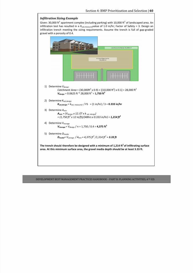
7/30/2019 Low Impact Developement Manual Part B
http://slidepdf.com/reader/full/low-impact-developement-manual-part-b 47/68
Section 4: BMP Prioritization and Selection |40
DEVELOPMENT BEST MANAGEMENT PRACTICES HANDBOOK – PART B: PLANNING ACTIVITIES, 4 TH ED.
Infiltration Sizing Example
Given: 30,000 ft2
apartment complex (including parking) with 10,000 ft2
of landscaped area. An
infiltration test has resulted in a Ksat,measuredvalue of 1.0 in/hr; Factor of Safety = 3. Design an
infiltration trench meeting the sizing requirements. Assume the trench is full of gap‐graded
gravel with a porosity of 0.4.
1) Determine V design
Catchment Area = (30,000ft2
x 0.9) + [(10,000 ft2) x 0.1] = 28,000 ft
2
V design = 0.0625 ft * 28,000 ft2
= 1,750 ft3
2) Determine Ksat,design
K sat,design = ksat, measured / FS = (1 in/hr) / 3 = 0.333 in/hr
3) Determine Amin
Amin = (V design x 12 /(T x k sat, design )
= (1,750 ft 3 x 12 in/ft)/(48hrs x 0.333 in/hr) = 1,214 ft 2
4) Determine Vstorage
V storage = Vdesign / n = 1,750 / 0.4 = 4,375 ft3
5) Determine Dmedia
Dmedia= V storage / Amin
= 4,375 ft 3 /1,314 ft
2 = 3.33 ft
The trench should therefore be designed with a minimum of 1,214 ft2
of infiltrating surface
area. At
this
minimum
surface
area,
the
gravel
media
depth
should
be
at
least
3.33
ft.
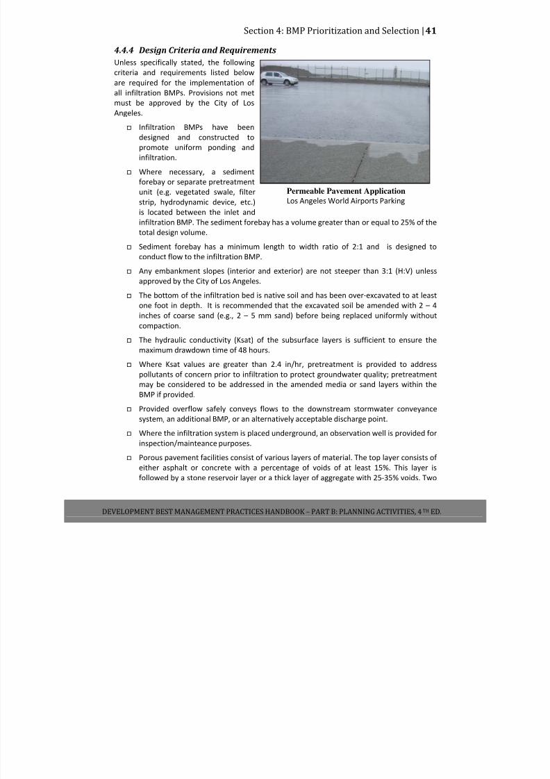
7/30/2019 Low Impact Developement Manual Part B
http://slidepdf.com/reader/full/low-impact-developement-manual-part-b 48/68
Section 4: BMP Prioritization and Selection |41
DEVELOPMENT BEST MANAGEMENT PRACTICES HANDBOOK – PART B: PLANNING ACTIVITIES, 4 TH ED.
4.4.4 Design Criteria and Requirements Unless specifically stated, the following
criteria and requirements listed below
are required for the implementation of
all infiltration BMPs. Provisions not met
must be approved by the City of Los Angeles.
Infiltration BMPs have been
designed and constructed to
promote uniform ponding and
infiltration.
Where necessary, a sediment
forebay or separate pretreatment
unit (e.g. vegetated swale, filter
strip, hydrodynamic device, etc.)
is located between the inlet and
infiltration BMP. The sediment forebay has a volume greater than or equal to 25% of the
total design volume.
Sediment forebay has a minimum length to width ratio of 2:1 and is designed to
conduct flow to the infiltration BMP.
Any embankment slopes (interior and exterior) are not steeper than 3:1 (H:V) unless
approved by the City of Los Angeles.
The bottom of the infiltration bed is native soil and has been over‐excavated to at least
one foot in depth. It is recommended that the excavated soil be amended with 2 – 4
inches of coarse sand (e.g., 2 – 5 mm sand) before being replaced uniformly without
compaction.
The hydraulic conductivity (Ksat) of the subsurface layers is sufficient to ensure the
maximum drawdown time of 48 hours.
Where Ksat values are greater than 2.4 in/hr, pretreatment is provided to address
pollutants of concern prior to infiltration to protect groundwater quality; pretreatment
may be considered to be addressed in the amended media or sand layers within the
BMP if provided.
Provided overflow safely conveys flows to the downstream stormwater conveyance
system, an additional BMP, or an alternatively acceptable discharge point.
Where the infiltration system is placed underground, an observation well is provided for
inspection/mainteance purposes.
Porous pavement facilities consist of various layers of material. The top layer consists of
either asphalt or concrete with a percentage of voids of at least 15%. This layer is
followed by a stone reservoir layer or a thick layer of aggregate with 25‐35% voids. Two
Permeable Pavement Application
Los Angeles World Airports Parking
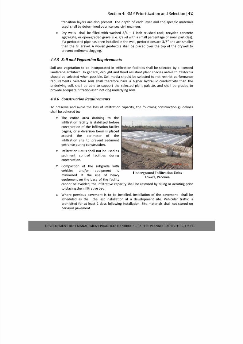
7/30/2019 Low Impact Developement Manual Part B
http://slidepdf.com/reader/full/low-impact-developement-manual-part-b 49/68
Section 4: BMP Prioritization and Selection |42
DEVELOPMENT BEST MANAGEMENT PRACTICES HANDBOOK – PART B: PLANNING ACTIVITIES, 4 TH ED.
transition layers are also present. The depth of each layer and the specific materials
used shall be determined by a licensed civil engineer.
Dry wells shall be filled with washed 3/4 – 1 inch crushed rock, recycled concrete
aggregate, or open‐graded gravel (i.e. gravel with a small percentage of small particles).
If a perforated pipe has been installed in the well, perforations are 3/8” and are smaller
than the fill gravel. A woven geotextile shall be placed over the top of the drywell to
prevent sediment clogging.
4.4.5 Soil and Vegetation Requirements
Soil and vegetation to be incorporated in infiltration facilities shall be selected by a licensed
landscape architect. In general, drought and flood resistant plant species native to California
should be selected when possible. Soil media should be selected to not restrict performance
requirements. Selected soils shall therefore have a higher hydraulic conductivity than the
underlying soil, shall be able to support the selected plant palette, and shall be graded to
provide adequate filtration as to not clog underlying soils.
4.4.6 Construction Requirements
To preserve and avoid the loss of infiltration capacity, the following construction guidelines
shall be adhered to:
The entire area draining to the
infiltration facility is stabilized before
construction of the infiltration facility
begins, or a diversion berm is placed
around the perimeter of the
infiltration site to prevent sediment
entrance during construction.
Infiltration BMPs shall not be used as
sediment control facilities during
construction.
Compaction of the subgrade with
vehicles and/or equipment is
minimized. If the use of heavy
equipment on the base of the facility
cannot be avoided, the infiltrative capacity shall be restored by tilling or aerating prior
to placing the infiltrative bed.
Where pervious pavement is to be installed, installation of the pavement shall be
scheduled as the the last installation at a development site. Vehicular traffic is
prohibited for at least 2 days following installation. Site materials shall not stored on
pervious pavement.
Underground Infiltration Units
Lowe’s, Pacoima
7/30/2019 Low Impact Developement Manual Part B
http://slidepdf.com/reader/full/low-impact-developement-manual-part-b 50/68
Section 4: BMP Prioritization and Selection |43
DEVELOPMENT BEST MANAGEMENT PRACTICES HANDBOOK – PART B: PLANNING ACTIVITIES, 4 TH ED.
4.4.7 Operations and Maintenance
Frequent inspections of the infiltration facilities shall occur to ensure that surface
ponding infiltrates into the subsurface completely within the design drawdown time
following storms. If vector breeding is taking place at a site as a result of contained
stormwater or inadequately maintained BMPs, the Greater Los Angeles County Vector Control District has the ability to fine site owners for violating the California Health and
Safety Code (Section 2060 – 2067).
Regular inspections shall take place to ensure that the pretreatment sediment removal
BMP/forebay is working efficiently. Sediment buildup exceeding 50% of the forebay
sediment storage capacity shall be removed.
The infiltration facility shall be maintained to prevent clogging. Maintenance activities
include checking for debris/sediment accumulation and removal of such debris.
Facility soil (if applicable) shall be maintained. Flow entrances, ponding areas, and
surface overflow areas will be inspected for erosion periodically. Soil and/or mulch will
be replaced as necessary to maintain the long‐term design infiltration rate for the life of
the project.
Site vegetation shall be maintained as frequently as necessary to maintain the aesthetic
apperance of the site as well as the filtration capabilities (where applicable). This
includes the removal of fallen, dead, and/or invasive plants, watering as necessary, and
the replanting and/or reseeding of vegetation for reestablishment as necessary.
Pervious pavement areas that are damaged or clogged shall be replaced/repaired per
manufacture’s recommendation as needed.
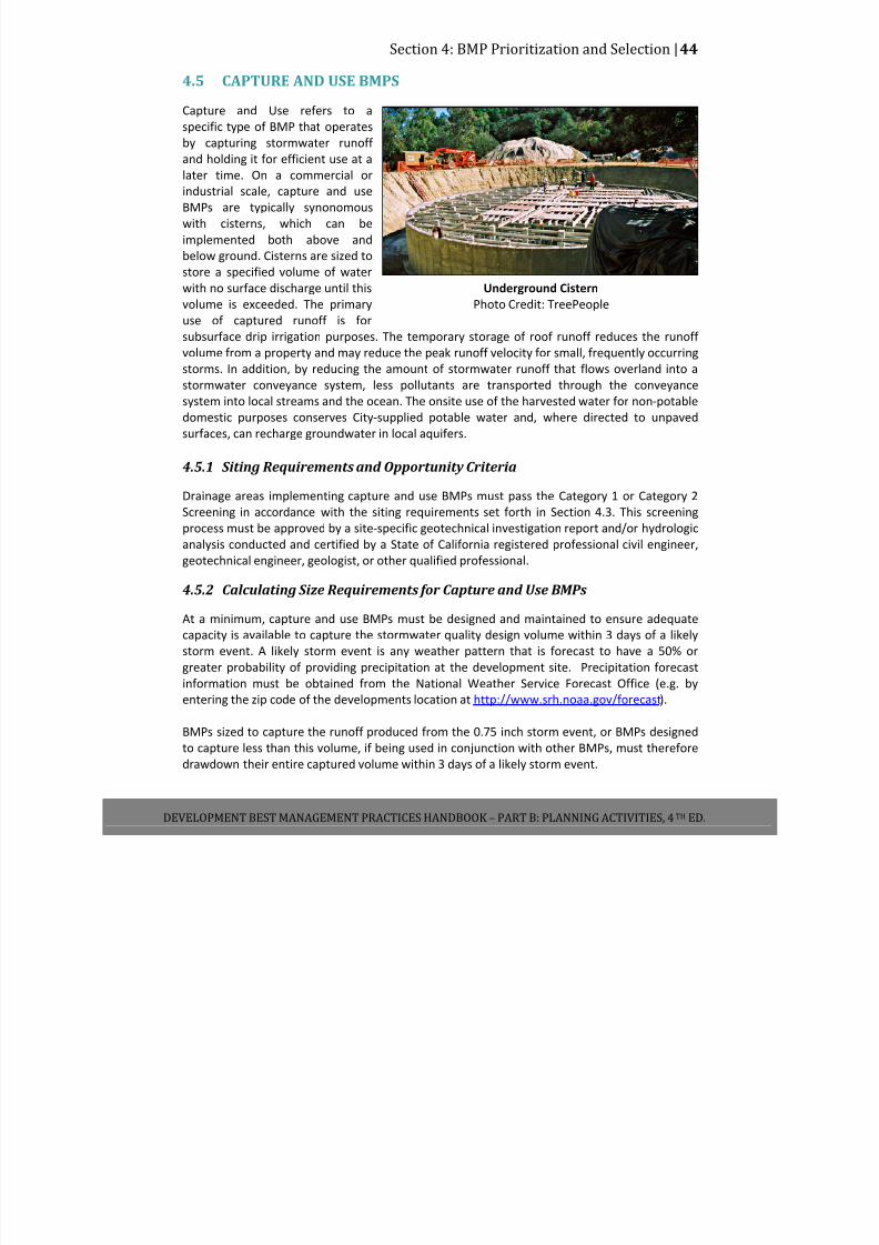
7/30/2019 Low Impact Developement Manual Part B
http://slidepdf.com/reader/full/low-impact-developement-manual-part-b 51/68
Section 4: BMP Prioritization and Selection |44
DEVELOPMENT BEST MANAGEMENT PRACTICES HANDBOOK – PART B: PLANNING ACTIVITIES, 4 TH ED.
4.5 CAPTURE AND USE BMPS
Capture and Use refers to a
specific type of BMP that operates
by capturing stormwater runoff
and holding it for efficient use at a
later time. On a commercial or
industrial scale, capture and use
BMPs are typically synonomous
with cisterns, which can be
implemented both above and
below ground. Cisterns are sized to
store a specified volume of water
with no surface discharge until this
volume is exceeded. The primary
use of captured runoff is for
subsurface drip irrigation purposes. The temporary storage of roof runoff reduces the runoff volume from a property and may reduce the peak runoff velocity for small, frequently occurring
storms. In addition, by reducing the amount of stormwater runoff that flows overland into a
stormwater conveyance system, less pollutants are transported through the conveyance
system into local streams and the ocean. The onsite use of the harvested water for non‐potable
domestic purposes conserves City‐supplied potable water and, where directed to unpaved
surfaces, can recharge groundwater in local aquifers.
4.5.1 Siting Requirements and Opportunity Criteria
Drainage areas implementing capture and use BMPs must pass the Category 1 or Category 2
Screening in accordance with the siting requirements set forth in Section 4.3. This screening
process must be approved by a site‐specific geotechnical investigation report and/or hydrologic
analysis conducted and certified by a State of California registered professional civil engineer,
geotechnical engineer, geologist, or other qualified professional.
4.5.2 Calculating Size Requirements for Capture and Use BMPs
At a minimum, capture and use BMPs must be designed and maintained to ensure adequate
capacity is available to capture the stormwater quality design volume within 3 days of a likely
storm event. A likely storm event is any weather pattern that is forecast to have a 50% or
greater
probability
of
providing
precipitation
at
the
development
site.
Precipitation
forecast
information must be obtained from the National Weather Service Forecast Office (e.g. by
entering the zip code of the developments location at http://www.srh.noaa.gov/forecast).
BMPs sized to capture the runoff produced from the 0.75 inch storm event, or BMPs designed
to capture less than this volume, if being used in conjunction with other BMPs, must therefore
drawdown their entire captured volume within 3 days of a likely storm event.
Underground Cistern
Photo Credit: TreePeople
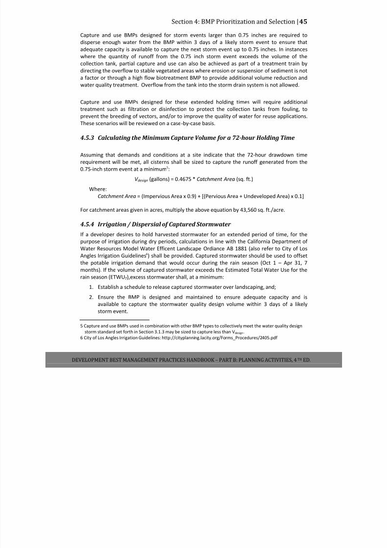
7/30/2019 Low Impact Developement Manual Part B
http://slidepdf.com/reader/full/low-impact-developement-manual-part-b 52/68
Section 4: BMP Prioritization and Selection |45
DEVELOPMENT BEST MANAGEMENT PRACTICES HANDBOOK – PART B: PLANNING ACTIVITIES, 4 TH ED.
Capture and use BMPs designed for storm events larger than 0.75 inches are required to
disperse enough water from the BMP within 3 days of a likely storm event to ensure that
adequate capacity is available to capture the next storm event up to 0.75 inches. In instances
where the quantity of runoff from the 0.75 inch storm event exceeds the volume of the
collection tank, partial capture and use can also be achieved as part of a treatment train by
directing the overflow to stable vegetated areas where erosion or suspension of sediment is not
a factor or through a high flow biotreatment BMP to provide additional volume reduction and
water quality treatment. Overflow from the tank into the storm drain system is not allowed.
Capture and use BMPs designed for these extended holding times will require additional
treatment such as filtration or disinfection to protect the collection tanks from fouling, to
prevent the breeding of vectors, and/or to improve the quality of water for reuse applications.
These scenarios will be reviewed on a case‐by‐case basis.
4.5.3 Calculating the Minimum Capture Volume for a 72-hour Holding Time
Assuming that demands and conditions at a site indicate that the 72‐hour drawdown time
requirement will be met, all cisterns shall be sized to capture the runoff generated from the
0.75‐inch storm event at a minimum5:
V design (gallons) = 0.4675 * Catchment Area (sq. ft.)
Where:
Catchment Area = (Impervious Area x 0.9) + [(Pervious Area + Undeveloped Area) x 0.1]
For catchment areas given in acres, multiply the above equation by 43,560 sq. ft./acre.
4.5.4 Irrigation
/
Dispersial
of
Captured
Stormwater
If a developer desires to hold harvested stormwater for an extended period of time, for the
purpose of irrigation during dry periods, calculations in line with the California Department of
Water Resources Model Water Efficent Landscape Ordiance AB 1881 (also refer to City of Los
Angles Irrigation Guidelines6) shall be provided. Captured stormwater should be used to offset
the potable irrigation demand that would occur during the rain season (Oct 1 – Apr 31, 7
months). If the volume of captured stormwater exceeds the Estimated Total Water Use for the
rain season (ETWU7),excess stormwater shall, at a minimum:
1. Establish a schedule to release captured stormwater over landscaping, and;
2. Ensure the BMP is designed and maintained to ensure adequate capacity and is
available to capture the stormwater quality design volume within 3 days of a likely
storm event.
5 Capture and use BMPs used in combination with other BMP types to collectively meet the water quality design
storm standard set forth in Section 3.1.3 may be sized to capture less than Vdesign.
6 City of Los Angles Irrigation Guidelines: http://cityplanning.lacity.org/Forms_Procedures/2405.pdf
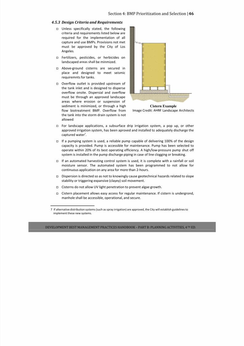
7/30/2019 Low Impact Developement Manual Part B
http://slidepdf.com/reader/full/low-impact-developement-manual-part-b 53/68
Section 4: BMP Prioritization and Selection |46
DEVELOPMENT BEST MANAGEMENT PRACTICES HANDBOOK – PART B: PLANNING ACTIVITIES, 4 TH ED.
4.5.3 Design Criteria and Requirements Unless specifically stated, the following
criteria and requirements listed below are
required for the implementation of all
capture and use BMPs. Provisions not met
must be approved by the City of Los
Angeles.
Fertilizers, pesticides, or herbicides on
landscaped areas shall be minmized.
Above‐ground cisterns are secured in
place and designed to meet seismic
requiremnts for tanks.
Overflow outlet is provided upstream of
the tank inlet and is designed to disperse
overflow onsite. Dispersial and overflow must be through an approved landscape
areas where erosion or suspension of
sediment is minimized, or through a high
flow biotreatment BMP. Overflow from
the tank into the storm drain system is not
allowed.
For landscape applications, a subsurface drip irrigation system, a pop up, or other
approved irrigation system, has been aproved and installed to adequately discharge the
captured water7.
If a pumping system is used, a reliable pump capable of delivering 100% of the design
capacity is provided. Pump is accessible for maintenance. Pump has been selected to
operate within 20% of its best operating efficiency. A high/low‐pressure pump shut off
system is installed in the pump discharge piping in case of line clogging or breaking.
If an automated harvesting control system is used, it is complete with a rainfall or soil
moisture sensor. The automated system has been programmed to not allow for
continuous application on any area for more than 2‐hours.
Dispersion is directed so as not to knowingly cause geotechnical hazards related to slope
stability or triggering expansive (clayey) soil movement.
Cisterns do not allow UV light penetration to prevent algae growth.
Cistern placement allows easy access for regular maintenance. If cistern is undergrond,
manhole shall be accessible, operational, and secure.
7 If alternative distribution systems (such as spray irrigation) are approved, the City will establish guidelines to
implement these new systems.
Cistern Example
Image Credit: AHBE Landscape Architects

7/30/2019 Low Impact Developement Manual Part B
http://slidepdf.com/reader/full/low-impact-developement-manual-part-b 54/68
Section 4: BMP Prioritization and Selection |47
DEVELOPMENT BEST MANAGEMENT PRACTICES HANDBOOK – PART B: PLANNING ACTIVITIES, 4 TH ED.
Refer to County of Los Angeles , Department of Health Services for additional guidelines
and requiremnets.
Provide observation access for vector inspection and treatment.
4.5.4 Operations
and
Maintenance
Cistern components, including spigots, downspouts, and inlets will be inspected 4 times
annually to ensure proper functionality. Parts will be repaired or replaced as needed.
Cisterns and their components will be cleaned as necessary to prevent algae growth and
the breeding of vectors.
Dispersion areas will be maintained to remove trash and debris, loose vegetation, and
rehabilitate any areas of bare soil.
Effective energy dissipation and uniform flow spreading methods will be employed to
prevent erosion and facilitate dispersion.
Cisterns will be emptied as necessary to prevent vector breeding, unless exclusion
devices are implemented to prevent vector access. If vector breeding is taking place at a
site as a result of contained stormwater or inadequately maintained BMPs, the Greater
Los Angeles County Vector Control District has the ability to fine site owners for violating
the California Health and Safety Code (Section 2060 – 2067).
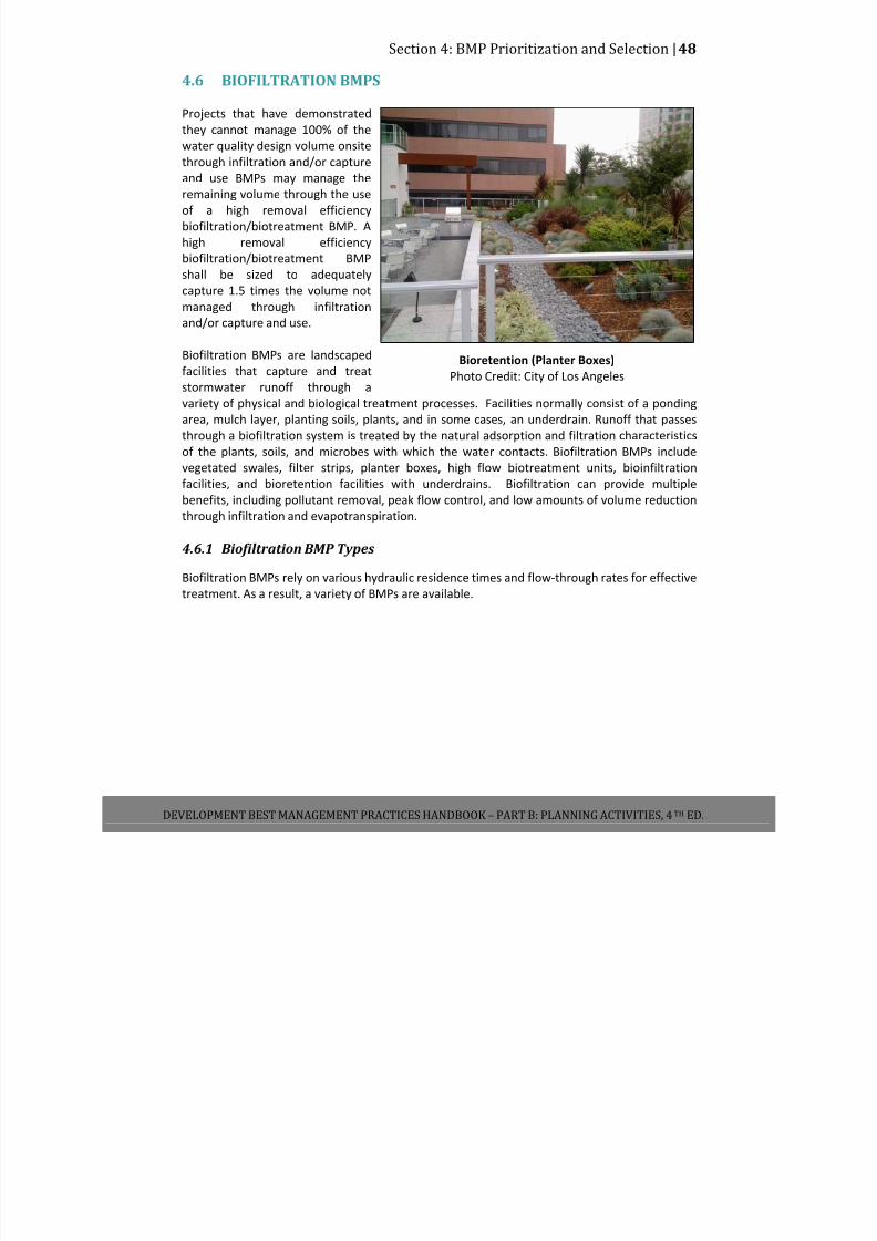
7/30/2019 Low Impact Developement Manual Part B
http://slidepdf.com/reader/full/low-impact-developement-manual-part-b 55/68
Section 4: BMP Prioritization and Selection |48
DEVELOPMENT BEST MANAGEMENT PRACTICES HANDBOOK – PART B: PLANNING ACTIVITIES, 4 TH ED.
4.6 BIOFILTRATION BMPS
Projects that have demonstrated
they cannot manage 100% of the
water quality design volume onsite
through
infiltration
and/or
capture
and use BMPs may manage the
remaining volume through the use
of a high removal efficiency
biofiltration/biotreatment BMP. A
high removal efficiency
biofiltration/biotreatment BMP
shall be sized to adequately
capture 1.5 times the volume not
managed through infiltration
and/or capture and use.
Biofiltration BMPs are landscaped
facilities that capture and treat
stormwater runoff through a
variety of physical and biological treatment processes. Facilities normally consist of a ponding
area, mulch layer, planting soils, plants, and in some cases, an underdrain. Runoff that passes
through a biofiltration system is treated by the natural adsorption and filtration characteristics
of the plants, soils, and microbes with which the water contacts. Biofiltration BMPs include
vegetated swales, filter strips, planter boxes, high flow biotreatment units, bioinfiltration
facilities, and bioretention facilities with underdrains. Biofiltration can provide multiple
benefits, including pollutant removal, peak flow control, and low amounts of volume reduction through infiltration and evapotranspiration.
4.6.1 Biofiltration BMP Types
Biofiltration BMPs rely on various hydraulic residence times and flow‐through rates for effective
treatment. As a result, a variety of BMPs are available.
Bioretention (Planter Boxes)
Photo Credit: City of Los Angeles
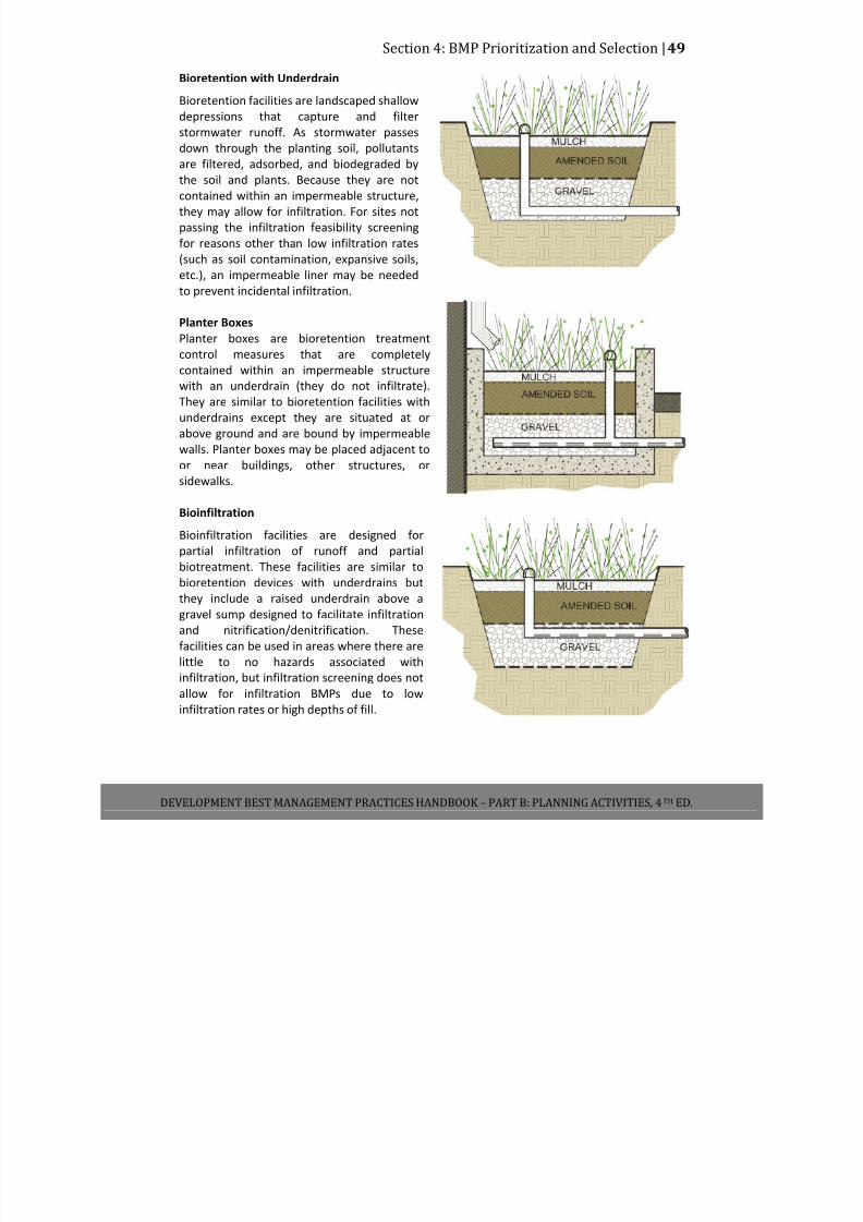
7/30/2019 Low Impact Developement Manual Part B
http://slidepdf.com/reader/full/low-impact-developement-manual-part-b 56/68
Section 4: BMP Prioritization and Selection |49
DEVELOPMENT BEST MANAGEMENT PRACTICES HANDBOOK – PART B: PLANNING ACTIVITIES, 4 TH ED.
Bioretention with Underdrain
Bioretention facilities are landscaped shallow
depressions that capture and filter
stormwater runoff. As stormwater passes
down through the planting soil, pollutants
are filtered, adsorbed, and biodegraded by
the soil and plants. Because they are not
contained within an impermeable structure,
they may allow for infiltration. For sites not
passing the infiltration feasibility screening
for reasons other than low infiltration rates
(such as soil contamination, expansive soils,
etc.), an impermeable liner may be needed
to prevent incidental infiltration.
Planter Boxes
Planter boxes are bioretention treatment
control measures that are completely
contained within an impermeable structure
with an underdrain (they do not infiltrate).
They are similar to bioretention facilities with
underdrains except they are situated at or
above ground and are bound by impermeable
walls. Planter boxes may be placed adjacent to
or near buildings, other structures, or
sidewalks.
Bioinfiltration
Bioinfiltration facilities are designed for
partial infiltration of runoff and partial
biotreatment. These facilities are similar to
bioretention devices with underdrains but
they include a raised underdrain above a
gravel sump designed to facilitate infiltration
and nitrification/denitrification. These
facilities can be used in areas where there are
little to no hazards associated with
infiltration, but infiltration screening does not
allow for infiltration BMPs due to low
infiltration rates or high depths of fill.
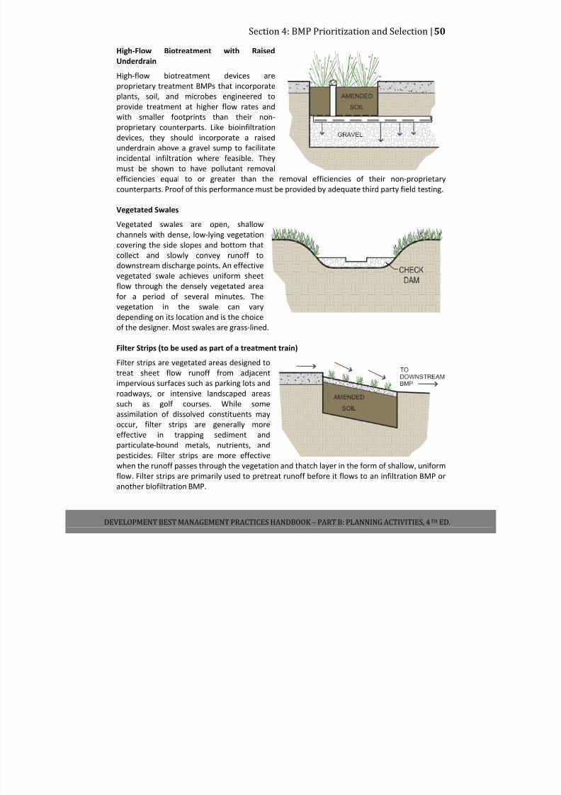
7/30/2019 Low Impact Developement Manual Part B
http://slidepdf.com/reader/full/low-impact-developement-manual-part-b 57/68
Section 4: BMP Prioritization and Selection |50
DEVELOPMENT BEST MANAGEMENT PRACTICES HANDBOOK – PART B: PLANNING ACTIVITIES, 4 TH ED.
High‐Flow Biotreatment with Raised
Underdrain
High‐flow biotreatment devices are
proprietary treatment BMPs that incorporate
plants, soil, and microbes engineered to
provide treatment at higher flow rates and
with smaller footprints than their non‐
proprietary counterparts. Like bioinfiltration
devices, they should incorporate a raised
underdrain above a gravel sump to facilitate
incidental infiltration where feasible. They
must be shown to have pollutant removal
efficiencies equal to or greater than the removal efficiencies of their non‐proprietary
counterparts. Proof of this performance must be provided by adequate third party field testing.
Vegetated Swales
Vegetated swales are open, shallow
channels with dense, low‐lying vegetation
covering the side slopes and bottom that
collect and slowly convey runoff to
downstream discharge points. An effective
vegetated swale achieves uniform sheet
flow through the densely vegetated area
for a period of several minutes. The
vegetation in the swale can vary
depending on its location and is the choice
of the designer. Most swales are grass‐lined.
Filter Strips (to be used as part of a treatment train)
Filter strips are vegetated areas designed to
treat sheet flow runoff from adjacent
impervious surfaces such as parking lots and
roadways, or intensive landscaped areas
such as golf courses. While some
assimilation of dissolved constituents may
occur, filter strips are generally more
effective in trapping sediment and
particulate‐bound metals, nutrients, and
pesticides. Filter strips are more effective
when the runoff passes through the vegetation and thatch layer in the form of shallow, uniform
flow. Filter strips are primarily used to pretreat runoff before it flows to an infiltration BMP or
another biofiltration BMP.

7/30/2019 Low Impact Developement Manual Part B
http://slidepdf.com/reader/full/low-impact-developement-manual-part-b 58/68
Section 4: BMP Prioritization and Selection |51
DEVELOPMENT BEST MANAGEMENT PRACTICES HANDBOOK – PART B: PLANNING ACTIVITIES, 4 TH ED.
4.6.2 Siting Requirements and Opportunity Criteria
Sites with plans to implement high removal efficiency biofiltration/biotreatment systems for
the management of stormwater must first be screened for infiltration and capture and use BMP
feasibility. Biofiltration should be implemented to treat all runoff onsite to the maximum extent
feasible at sites incapable of implementing infiltration and/or capture and use BMPs as a result
of the feasibility screening process set forth in this handbook.
Sites implementing biofiltration BMPs must have sufficient area available to ensure that BMPs
produce adequate contact time for filtration to occur. For biofiltration BMPs with underdrains,
sufficient vertical relief must exist to permit vertical percolation through the soil media to the
underdrain below. For biofiltration BMPs with incidental infiltration, it must be demonstrated
that there are no hazards associated with infiltration (i.e. infiltration screening does not allow
for infiltration BMPs due to low infiltration rates or high depths of fill).
4.6.3 Calculating
Size
Requirements
for
Biofiltration
BMPs
Biofiltration BMPs should be designed according to the requirements listed in Table 4.5 and
outlined in the section below.
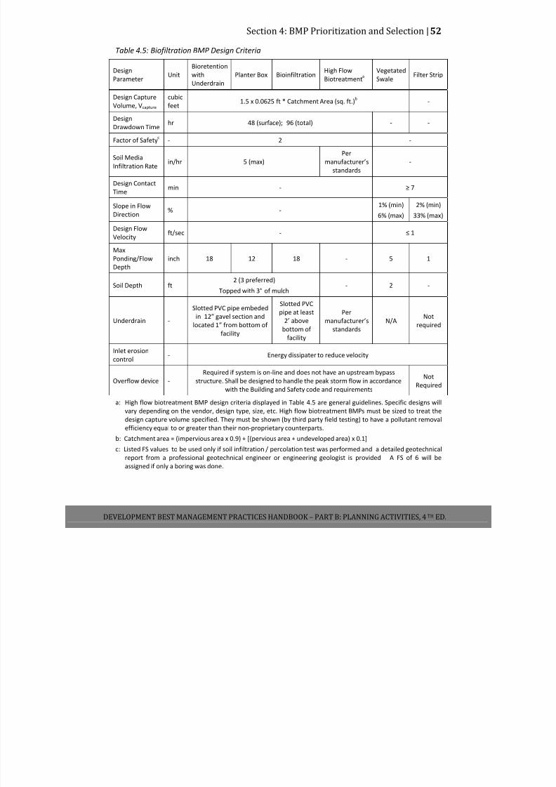
7/30/2019 Low Impact Developement Manual Part B
http://slidepdf.com/reader/full/low-impact-developement-manual-part-b 59/68
Section 4: BMP Prioritization and Selection |52
DEVELOPMENT BEST MANAGEMENT PRACTICES HANDBOOK – PART B: PLANNING ACTIVITIES, 4 TH ED.
Table 4.5: Biofiltration BMP Design Criteria
Design
Parameter Unit
Bioretention
with
Underdrain
Planter Box Bioinfiltration High Flow
Biotreatmenta
Vegetated
Swale Filter Strip
Design Capture
Volume, Vcapture
cubic
feet
1.5 x 0.0625 ft * Catchment Area (sq. ft.)b
‐
Design
Drawdown Time hr 48 (surface); 96 (total) ‐ ‐
Factor of Safetyc
‐ 2 ‐
Soil Media
Infiltration Rate in/hr 5 (max)
Per
manufacturer’s
standards
‐
Design Contact
Time min ‐ ≥ 7
Slope in Flow
Direction %‐
1% (min)
6% (max)
2% (min)
33% (max)
Design Flow
Velocity ft/sec ‐ ≤ 1
Max
Ponding/Flow
Depth
inch 18 12 18 ‐ 5 1
Soil Depth ft
2 (3 preferred)
Topped with 3” of mulch
‐ 2 ‐
Underdrain ‐
Slotted PVC pipe embeded
in
12”
gavel
section
and
located 1” from bottom of
facility
Slotted PVC
pipe at least
2’ above
bottom of
facility
Per
manufacturer’s
standards
N/A Not
required
Inlet erosion
control ‐ Energy dissipater to reduce velocity
Overflow device ‐
Required if system is on‐line and does not have an upstream bypass
structure. Shall be designed to handle the peak storm flow in accordance
with the Building and Safety code and requirements
Not
Required
a: High flow biotreatment BMP design criteria displayed in Table 4.5 are general guidelines. Specific designs will
vary depending on the vendor, design type, size, etc. High flow biotreatment BMPs must be sized to treat the
design capture volume specified. They must be shown (by third party field testing) to have a pollutant removal
efficiency equal to or greater than their non‐proprietary counterparts.
b: Catchment area = (impervious area x 0.9) + [(pervious area + undeveloped area) x 0.1]
c: Listed FS values to be used only if soil infiltration / percolation test was performed and a detailed geotechnical
report from a professional geotechnical engineer or engineering geologist is provided A FS of 6 will be
assigned if only a boring was done.

7/30/2019 Low Impact Developement Manual Part B
http://slidepdf.com/reader/full/low-impact-developement-manual-part-b 60/68
Section 4: BMP Prioritization and Selection |53
DEVELOPMENT BEST MANAGEMENT PRACTICES HANDBOOK – PART B: PLANNING ACTIVITIES, 4 TH ED.
Bioretention, Planter Box, Bioinfiltration, and High-Flow Biotreatment Sizing
With the exception of swales and filter strips, biofiltration facilities can be sized using one of
two methods: a simple sizing method or a hydrologic routing modeling method. With either
method the design capture volume must be completely infiltrated within the drawdown time
shown in Table 4.5. Steps for the simple sizing method are provided below.
Step 1: Calculate the Design Volume
Biofiltration facilities shall be sized to capture and treat 150% of the design capture volume
(V design) based on the runoff produced from a 0.75‐inch (0.0625 ft) storm event.
V design (cu ft) = 1.5 * 0.0625 ft * Catchment Area (sq. ft.)
Where
Catchment area = (Impervious Area x 0.9) + [(Pervious Area + Undeveloped Area) x 0.1]
Step 2: Determine the Design Infiltration Rate
The infiltration rate will decline between maintenance cycles as the surface and underlying soil matrix becomes clogged with particulates and debris. Monitoring of actual facility performance
has shown that the full‐scale infiltration rate is far lower than the rate measured by small‐scale
testing. It is important that adequate conservatism is incorporated in the sizing of facilities
depending on a site’s infiltration rate and expected surface loading. Unlike infiltration BMPs,
the measured infiltration rate discussed here is the infiltration rate of the filter media bed or
engineered surface soils in the biofilter. A target long‐term Ksat,media of 5 in/hr is recommended
for non‐proprietary amended soil media. Facility maintenance is required to maintain the
infiltration rate for the life of the project. Infiltration rates used for design must be divided by
the appropriate factors of safety.
Ksat,design = Ksat,media/FS
Step 3: Calculate the BMP Ponding Depth
Select a ponding depth (d p) that satisfies geometric criteria and is congruent with the
constraints of the site. The ponding depth must satisfy the maximum ponding depth constraint
shown in Table 4.5 as well as the following:
d p (ft) = (Ksat,design x T) / 12
Where:
d p = Ponding depth (ft)
K sat,design= Design infiltration rate of filter media (in/hr)
T = Required surface drain time (hrs), from Table 4.5
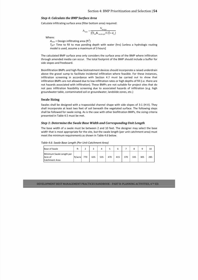
7/30/2019 Low Impact Developement Manual Part B
http://slidepdf.com/reader/full/low-impact-developement-manual-part-b 61/68
Section 4: BMP Prioritization and Selection |54
DEVELOPMENT BEST MANAGEMENT PRACTICES HANDBOOK – PART B: PLANNING ACTIVITIES, 4 TH ED.
Step 4: Calculate the BMP Surface Area
Calculate infiltrating surface area (filter bottom area) required:
( ) ]d /12KT[
VA
pdesignsat,fill
design
min+
=
Where: Amin = Design infiltrating area (ft
2)
T fill = Time to fill to max ponding depth with water (hrs) [unless a hydrologic routing
model is used, assume a maximum of 3 hours]
The calculated BMP surface area only considers the surface area of the BMP where infiltration
through amended media can occur. The total footprint of the BMP should include a buffer for
side slopes and freeboard.
Bioinfiltration BMPs and high‐flow biotreatment devices should incorporate a raised underdrain
above the gravel sump to facilitate incidental infiltration where feasible. For these instances,
infiltration screening in accordance with Section 4.2 must be carried out to show that
infiltration BMPs are not allowed due to low infiltration rates or high depths of fill (i.e. there are
not hazards associated with infiltration). These BMPs are not suitable for project sites that do
not pass infiltration feasibility screening due to associated hazards of infiltration (e.g. high
groundwater table, contaminated soil or groundwater, landslide zones, etc.)
Swale Sizing
Swales shall be designed with a trapezoidal channel shape with side slopes of 3:1 (H:V). They
shall incorporate at least two feet of soil beneath the vegetated surface. The following steps
shall be followed for swale sizing. As is the case with other biofiltration BMPs, the sizing criteria
presented in Table 4.5 must be met.
Step 1: Determine the Swale Base Width and Corresponding Unit Length
The base width of a swale must be between 2 and 10 feet. The designer may select the base
width that is most appropriate for the site, but the swale length (per unit catchment area) must
meet the minimum requirements as shown in Table 4.6 below.
Table 4.6: Swale Base Length (Per Unit Catchment Area)
Base of Swale ft 2 3 4 5 6 7 8 9 10
Minimum Swale Length per
Acre of
Catchment Area
ft/acre 770 635 535 470 415 370 335 305 285
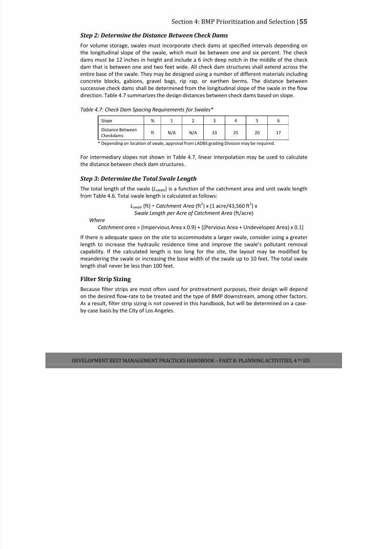
7/30/2019 Low Impact Developement Manual Part B
http://slidepdf.com/reader/full/low-impact-developement-manual-part-b 62/68
Section 4: BMP Prioritization and Selection |55
DEVELOPMENT BEST MANAGEMENT PRACTICES HANDBOOK – PART B: PLANNING ACTIVITIES, 4 TH ED.
Step 2: Determine the Distance Between Check Dams
For volume storage, swales must incorporate check dams at specified intervals depending on
the longitudinal slope of the swale, which must be between one and six percent. The check
dams must be 12 inches in height and include a 6 inch deep notch in the middle of the check
dam that is between one and two feet wide. All check dam structures shall extend across the
entire base of the swale. They may be designed using a number of different materials including
concrete blocks, gabions, gravel bags, rip rap, or earthen berms. The distance between
successive check dams shall be determined from the longitudinal slope of the swale in the flow
direction. Table 4.7 summarizes the design distances between check dams based on slope.
Table 4.7: Check Dam Spacing Requirements for Swales*
Slope % 1 2 3 4 5 6
Distance Between
Checkdams ft N/A N/A 33 25 20 17
* Depending on location of swale, approval from LADBS grading Division may be required.
For intermediary slopes not shown in Table 4.7, linear interpolation may be used to calculate
the distance between check dam structures.
Step 3: Determine the Total Swale Length
The total length of the swale (Lswale) is a function of the catchment area and unit swale length
from Table 4.6. Total swale length is calculated as follows:
Lswale (ft) = Catchment Area (ft2) x (1 acre/43,560 ft
2) x
Swale Length per Acre of Catchment Area (ft/acre)
Where
Catchment area = (Impervious Area x 0.9) + [(Pervious Area + Undeveloped Area) x 0.1]
If there is adequate space on the site to accommodate a larger swale, consider using a greater
length to increase the hydraulic residence time and improve the swale’s pollutant removal
capability. If the calculated length is too long for the site, the layout may be modified by
meandering the swale or increasing the base width of the swale up to 10 feet. The total swale
length shall never be less than 100 feet.
Filter Strip Sizing
Because filter strips are most often used for pretreatment purposes, their design will depend
on the desired flow‐rate to be treated and the type of BMP downstream, among other factors. As a result, filter strip sizing is not covered in this handbook, but will be determined on a case‐
by‐case basis by the City of Los Angeles.
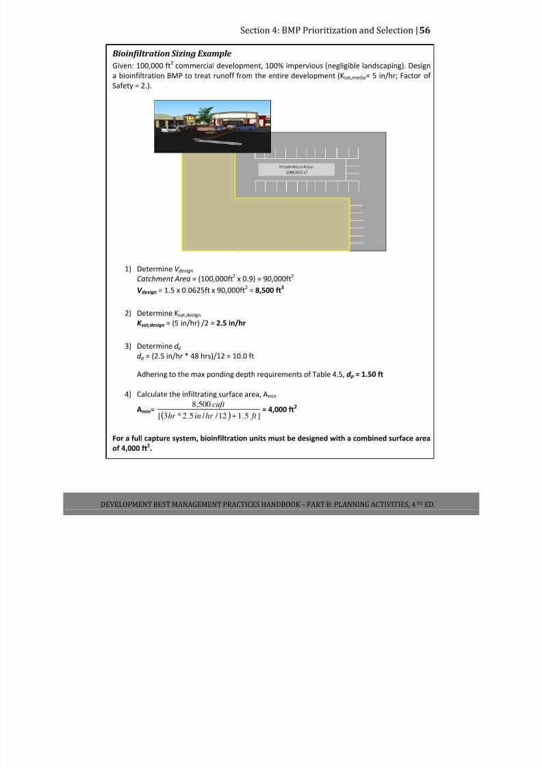
7/30/2019 Low Impact Developement Manual Part B
http://slidepdf.com/reader/full/low-impact-developement-manual-part-b 63/68
Section 4: BMP Prioritization and Selection |56
DEVELOPMENT BEST MANAGEMENT PRACTICES HANDBOOK – PART B: PLANNING ACTIVITIES, 4 TH ED.
Bioinfiltration Sizing Example
Given: 100,000 ft2 commercial development, 100% impervious (negligible landscaping). Design
a bioinfiltration BMP to treat runoff from the entire development (Ksat,media= 5 in/hr; Factor of
Safety = 2.).
1) Determine V design
Catchment Area = (100,000ft2
x 0.9) = 90,000ft2
V design = 1.5 x 0.0625ft x 90,000ft2
= 8,500 ft3
2) Determine Ksat,design
K sat,design = (5 in/hr) /2 = 2.5 in/hr
3) Determine d p
d p = (2.5 in/hr * 48 hrs)/12 = 10.0 ft
Adhering to the max ponding depth requirements of Table 4.5, d p = 1.50 ft
4) Calculate the infiltrating surface area, Amin
Amin=
( ) ]5.112 / / 5.2*3[
500,8
ft hr inhr
cuft
+
= 4,000 ft2
For a full capture system, bioinfiltration units must be designed with a combined surface area
of 4,000 ft2.

7/30/2019 Low Impact Developement Manual Part B
http://slidepdf.com/reader/full/low-impact-developement-manual-part-b 64/68
Section 4: BMP Prioritization and Selection |57
DEVELOPMENT BEST MANAGEMENT PRACTICES HANDBOOK – PART B: PLANNING ACTIVITIES, 4 TH ED.
4.6.4 Design Criteria and Requirements Unless specifically stated, all criteria and requirements listed below are required for the
implementation of all biofiltration BMPs. Provisions not met must be approved by the City of
Los Angeles.
Where applicable, biofiltration BMPs
shall be constructed with a minimum
planting soil depth of 2 feet (3 feet
preferred) and topped with 3 inches of
mulch.
Where applicable, biofiltration BMPs
shall be designed to drain below the
planting soil in less than 48 hours and
completely drain from the underdrains
in 96 hours.
Underdrains shall be constructed of
slotted PVC pipe, sloped at a minimum
0.5% and placed per Table 4.5
requirements. Underdrains drain freely
to a downstream stormwater
conveyance system, an additional BMP, or an alternatively acceptable discharge point.
If system is online, an overflow is present. The overflow safely conveys flows to the
downstream stormwater conveyance system, an additional BMP, or an alternatively
acceptable discharge point.
Inflow to
swales
shall
be
directed
towards
the
upstream
end
of
the
swale.
Bioinfiltration BMPs and high‐flow biotreatment BMPs designed for secondary
infiltration shall pass the infiltration feasibility screening for all hazardous criteria. If
necessary, weep holes shall be used to increase infiltration.
Swales shall be constructed with a bottom width between 2 and 10 feet. Check dams
shall be incorporated at the appropriate distances as specified in Table 4.7. Check dams
are 12 inches in height and include a 6 inch deep notch in the middle of the check dam
that is 1‐2 feet wide. Each check dam extends across the entire width of the swale’s
base.
Filter strips shall be constructed to extend across the full width of the tributary area.
They shall be designed with sufficient slope in the flow direction to prevent ponding.
They shall have a minimum length of 4 ft in the flow direction when sized for
pretreatment purposes.
Bioretention in a Parking Lot
Photo Credit: Geosyntec Consultants
7/30/2019 Low Impact Developement Manual Part B
http://slidepdf.com/reader/full/low-impact-developement-manual-part-b 65/68
Section 4: BMP Prioritization and Selection |58
DEVELOPMENT BEST MANAGEMENT PRACTICES HANDBOOK – PART B: PLANNING ACTIVITIES, 4 TH ED.
4.6.5 Soil and Vegetation Requirements
Soil and vegetation to be incorporated in biofiltration facilities shall be selected by a licensed
landscape architect. In general, drought and flood resistant plant species native to Southern
California should be selected when possible. Soil media should be selected to facilitate vigorous
plant growth and not restrict performance requirements. Where the project receiving waters
are impaired for nutrients, media should be selected to minimize the potential for leaching of
nutrients from biofiltration systems.
4.6.6 Operations and Maintenance
Biofiltration areas require annual plant, soil, and mulch layer maintenance to ensure optimum
infiltration, storage, and pollutant removal capabilities. In general, biofiltration maintenance
requirements are typical landscape care procedures. The following operations and maintenance
practices will be adhered to:
Facility soil will be maintained. Flow entrances, ponding areas, and surface overflow
areas will be inspected for erosion periodically. Soil and/or mulch will be replaced as
necessary to maintain an infiltration rate at or near the initial Ksat,designvalue for the
duration of the project.
Site vegetation will be maintained as frequently as necessary to maintain fire protection,
public safety, and the aesthetic appearance of the site as well as the filtration
capabilities. This includes the removal of fallen, dead, and/or invasive plants, watering
as necessary, and the replanting and/or reseeding of vegetation for reestablishment as
necessary. Swales and filters will be mowed as necessary.
BMP inlets will be inspected and maintained to ensure even flow enters the facility.
Sediment collecting at the inlet will be removed as necessary.
Proprietary devices will be inspected and maintained in accordance with the
requirements of the manufacturer.
7/30/2019 Low Impact Developement Manual Part B
http://slidepdf.com/reader/full/low-impact-developement-manual-part-b 66/68
Section 5: Offsite Mitigation Measures |59
DEVELOPMENT BEST MANAGEMENT PRACTICES HANDBOOK – PART B: PLANNING ACTIVITIES, 4 TH ED.
SECTION 5: OFFSITE MITIGATION MEASURES
5.1 OFFSITE MITGATION MEASURES
The option for offsite mitigation shall only be exercised after the following conditions have
been met:
1. All the stormwater management techniques allowed (i.e., in priority order of infiltration,
capture and use, treated through high removal efficiency biofiltration system) have
been exhausted (i.e. are deemed technically infeasible), and;
2. All applicable Standard Urban Stormwater Mitigation Plan (SUSMP) requirements are
implemented in order to maximize onsite compliance, and;
Offsite
project
BMPs
should
be
located
as
close
as
possible
to
the
project
site,
on
private
and/or
public land, and should address a mix of land uses similar to those included in the proposed
project. The offsite project shall not be located within waters of the U.S. and it shall be
demonstrated that equivalent pollutant removal is accomplished prior to discharge to waters of
the U.S.
For the remaining runoff that cannot feasibly be managed onsite, the project shall implement
offsite mitigation in either:
1. The public right of way immediately adjacent to the subject development and/or;
2. Within the same sub‐watershed (as defined as draining to the same hydrologic area as
defined in the Basin Plan) as the proposed project
Construction of an offsite mitigation project(s) shall achieve at least the same level of water
quality protection as if all of the runoff were retained onsite and also be sized to mitigate the
volume from the onsite and the tributary area from the adjacent street (from the crown of the
street to the curb face for the entire length of the development site). All City Departments will
assist the developer, when and where feasible, permitting and implementation of LID BMP
projects within the public right of way.
Construction work in the public right‐of ‐way will be the responsibility of the developer, and requires a “Revocable Permit” from the Department of Public Works, Bureau of Engineering
(BOE). The developer will also be required to file a covenant and agreement with the county
recorder’s office to insure the owner assumes full responsibility for perpetual maintenance of
the onsite and offsite BMP(s) executed by a covenant and agreement. The type of BOE permit

7/30/2019 Low Impact Developement Manual Part B
http://slidepdf.com/reader/full/low-impact-developement-manual-part-b 67/68
Section 5: Offsite Mitigation Measures |60
DEVELOPMENT BEST MANAGEMENT PRACTICES HANDBOOK – PART B: PLANNING ACTIVITIES, 4 TH ED.
required depends on the scope of construction work. Additional permit information and
detailed flowcharts can be found at: http://eng.lacity.org/techdocs/permits/index.htm
Green Infrastructure Projects
In an effort to assist developers the City has recently approved and adopted a series of green
street standard plans. These plans provide a series of standards that developers can implement
utilizing the public right of way immediately adjacent to the development. These standard plans
provide general requirements for green streets, parkway swales in major/secondary highways,
parkway swales in local/collector streets, parkway swales with no street parking, vegetated
stormwater curb extensions, and interlocking pavers for vehicular and pedestrian alleys. The
green street standard plans can be obtained from the Bureau of Engineering’s Website at:
• http://eng.lacity.org/techdocs/stdplans/s‐400.htm
• http://eng.lacity.org/techdocs/stdplans/Pdfs/Green%20Street%20Standard%20Plans%20FAQ%20Sheet_091010.pdf
Additional information on the City’s Green Streets and Green Alleys design Guidelines can be
found at: www.lastormwater.org

7/30/2019 Low Impact Developement Manual Part B
http://slidepdf.com/reader/full/low-impact-developement-manual-part-b 68/68
List of Appendices |61
Appendix A Development Planning Ordinances
Appendix B CEQA Mitigation Measures
Appendix C Contact List
Appendix D Plan Check Review Forms
Appendix E Small Scale Residential Prescriptive Measures
Appendix F All Other Development Volume Design Calculations
Appendix G Standard Urban Stormwater Mitigation Plan (SUSMP)
Appendix H Site Specific Mitigation Measures
Appendix I LA Department of Building and Safety Stormwater Infiltration Guidelines
Appendix J ULARA Watermaster Requirements
Appendix K County of LA Department of Public Health Policy and Operations Manual