Embed Size (px)
Citation preview
I.B. 32-100-lA
DESCRIPTION • INSTALLATION • MAINTENANCE
INSTRUCTIONS
Low-Voltage
METAL-ENCLOSED
SWITCHGEAR
WESTINGHOUSE ELECTRIC CORPORATION SWITCHGEAR DIVISION
EAST PITTSBURGH PLANT • EAST PITTSBURGH, PA.
SUPERSEDES I.B. 32-100-1 DECE MBER, 1952 (Rep. ll-66) Printed in U.S.A. www .
Elec
tricalP
artM
anua
ls . c
om
2
TABLE OF C ONTENTS
Part One DESCRIPTION Pages 7-18
Switchgear Having Types DB-15, DB-2 5 and DB- 50 Circuit Breakers . . . . . . . . . . . . 7
Stationary Structure . . . . . . . . . . . . . . . . . . . . . . . . . . . . . . . . . . . . . . . . . . . . . . . . . . . 7
Removable Element . . . . . . . . . . . . . . . . . . . . . . . . . . . . . . . . . . . . . . . . . . . . . . . . . . . . 8
Interlocks . . . . . . . . . . . . . . . . . . . . . . . . . . . . . . . . . . . . . . . . . . . . . . . . . . . . . . . . . . . . 9
Accessories . . . . . . . . . . . . . . . . . . . . . . . . . . . . . . . . . . . . . . . . . . . . . . . . . . . . . . . . . . . 10
Inserting the Removable Element . . . . . . . . . . . . . . . . . . . . . . . . . . . . . . . . . . . . . . . 1 0
Removing the Element. . . . . . . . . . . . . . . . . . . . . . . . . . . . . . . . . . . . . . . . . . . . . . . . . 11
Switchgear Having Type DA-7 5 Circuit Breakers . . . . . . . . . . . . . . . . . . . . . . . . . . . . 13
Interlocks . . . . . . . . . . . . . . . . . . . . . . . . . . . . . . . . . . . . . . . . . . . . . . . . . . . . . . . . . . . 13
Accessories . . . . . . . . . . . . . . . . . . . . . . . . . . . . . . . . . . . . . . . . . . . . . . . . . . . . . . . . . . . 14
Inserting the Removable Element . . . . . . . . . . . . . . . . . . . . . . . . . . . . . . . . . . . . . . . 14
Removing the Element . . . . . . . . . . . . . . . . . . . . . . . . . . . . . . . . . . . . . . . . . . . . . . . . . 14
Switchgear Having Type DA-100 Circuit Breakers . . . . . . . . . . . . . . . . . . . . . . . . . . . . 17
Stationary Structure . . . . . . . . . . . . . . . . . . . . . . . . . . . . . . . . . . . . . . . . . . . . . . . . . . . 17
Removable Element . . . . . . . . . . . . . . . . . . . . . . . . . . . . . . . . . . . . . . . . . . . . . . . . . . . . 17
Inserting the Removable Element . . . . . . . . . . . . . . . . . . . . . . . . . . . . . . . . . . . . . . . . 1 7
Removing the Element. . . . . . . . . . . . . . . . . . . . . . . . . . . . . . . . . . . . . . . . . . . . . . . . . 18
Part Two RECEIVING, HANDLING AND STORING Page 19
Receiving. . . . . . . . . . . . . . . . . . . . . . . . . . . . . . . . . . . . . . . . . . . . . . . . . . . . . . . . . . . . 19
Handling. . . . . . . . . . . • . . . . . . . . . . . . . . . . . . . . . . . . . . . . . . . . . . . . . . . . . . . . . . . . . 19
Storing. . . . ... . . . . . . . . . . . . . . . . . . . . . . . . . . . . . . . . . . . . . . . . . . . . . . . . . . . . . 19
Part Three INSTALLATION Pages 20-22
Foundation.. . . . . . . . . . . . . . . . . . . . . . . . . . . . . . . . . . . . . . . . . . . . . . . . . . . . . . . . . . 20
Placing of Stationary Structure . . . . . . . . . . . . . . . . . . . . . . . . . . . . . . . . . . . . . . . . . . 20
Power Connections . . . . . . . . . . . . . . . . . . . . . . . . . . . . . . . . . . . . . . . . . . . . . . . . . . . . 20
Ground Connection . . . . . . . . . . . . . . . . . . . . . . . . . . . . . . . . . . . . . . . . . . . . . . . . . . . . 21
Control Connection . . . . . . . . . . . . . . . . . . . . . . . . . . . . . . . . . . . . . . . . . . . . . . . . . . . . 21
Pre-operation Checks . . . . . . . . . . . . . . . . . . . . . . . . . . . . . . . . . . . . . . . . . . . . . . . . . . 22
Part Four INSPECTION AND MAINTENANCE Page 24
www . El
ectric
alPar
tMan
uals
. com

I.B. 32-100-lA L.V. METAL-ENCLOSED SWITCHGEAR
LIS T OF ILLUSTRATIONS Figure Page
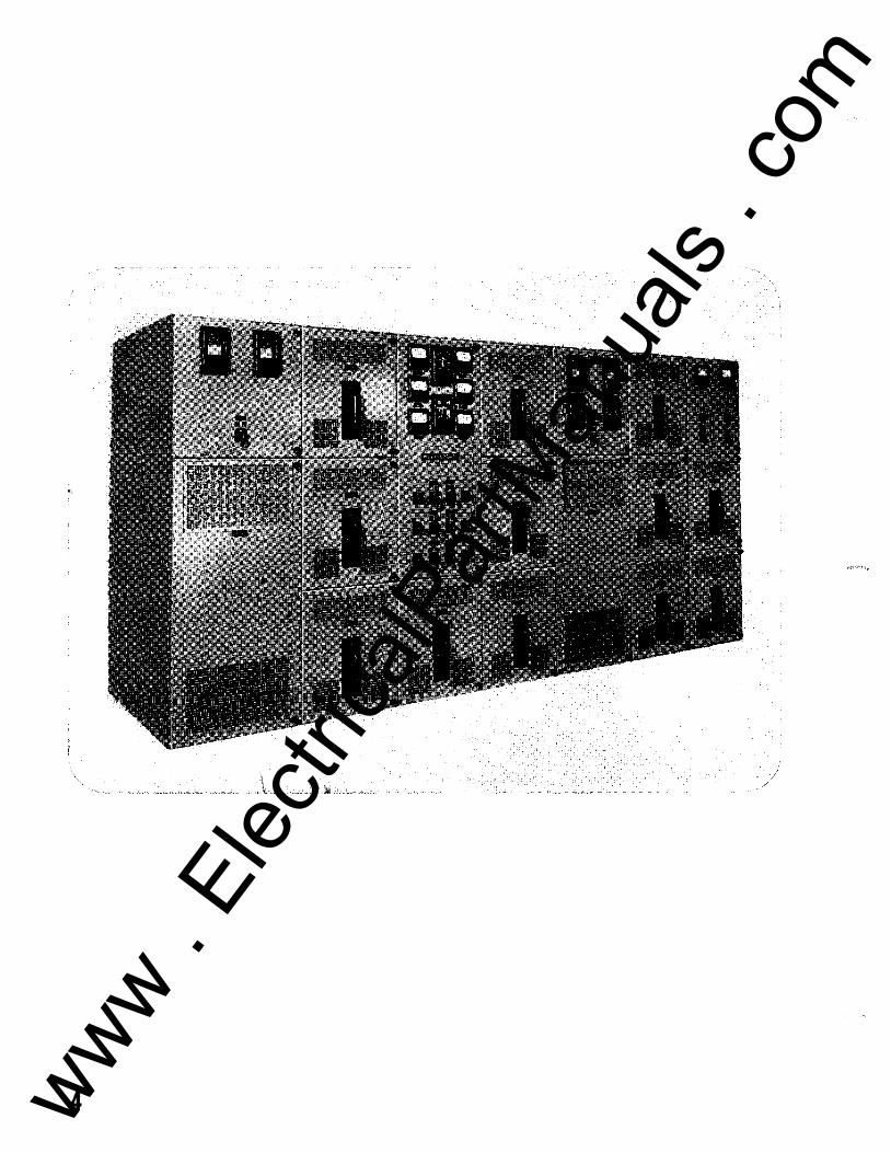
Frontispiece-Typical Installation of Indoor Metal-Enclosed Switchgear . . . . . . . . . . 4
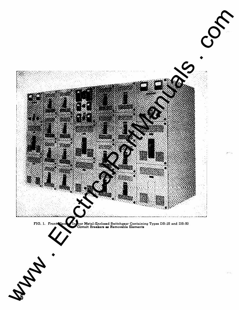
1 Front View of Indoor Metal-Enclosed Switchgear Containing Types DB-25
and DB-50 Circuit Breakers as Removable Elements . . . . . . . . . . . . . . . . . . . . . 6
2 Low-Voltage Switchgear Installed in an Outdoor Weatherproof Housing . . . . . 7
3 View of Rear Bus Compartment . . . . . . . . . . . . . . . . . . . . . . . . . . . . . . . . . . . . . . . . . 7
4 Micarta Bus Supports Arranged for One Bus Bar Per Phase . . . . . . . . . . . . . . . . 8
5 Micarta Bus Supports Arranged for Two Bus Bars Per Phase . . . . . . . . . . . . . . . . 8
6 Micarta Bus Supports Arranged for Three Bus Bars Per Phase . . . . . . . . . . . . . . 8 7 Compartment for Type DB- 1 5 Circuit Breaker . . . . . . . . . . . . . . . . . . . . . . . . . . . . 9
8 Removable Element for Type DB- 1 5 Circuit Breaker . . . . . . . . . . . . . . . . . . . . . . . 9
9 Compartment for Type DB-25 Circuit Breaker . . . . . . . . . . . . . . . . . . . . . . . . . . . . 1 0
1 0 Removable Element for Type DB-25 Circuit Breaker . . . . . . . . . . . . . . . . . . . . . . . 1 0
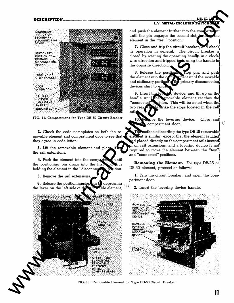
1 1 Compartment for Type DB-50 Circuit Breaker . . . . . . . . . . . . . . . . . . . . . . . . . . . . 1 1
1 2 Removable Element for Type DB-50 Circuit Breaker . . . . . . . . . . . . . . . . . . . . . . . 1 1
1 3 Switchgear Having Conjunction Parts for Mounting Smaller Removable
Elements . . . . . . . . . . . . . . . . . . . . . . . . . . . . . . . . . . . . . . . . . . . . . . . . . . . . . . . . . . 1 2
1 4 Placing Type DB-25 Removable Element on the Rail Extensions Using a Hoist . . . 1 2
1 5 Type DB-25 Element in Position on Rail Extensions Ready for Insertion in the
Compartment . . . . . . . . . . . . . . . . . . . . . . . . . . . . . . . . . . . . . . . . . . . . . . . . . . . . . . 1 2
1 6 Inserting a Type DB-25 Removable Element . . . . . . . . . . . . . . . . . . . . . . . . . . . . . . 1 3
1 7 Placing Type DB-50 Removable Element in Compartment Using the Handling
Carriage . . . . . . . . . . . . . . . . . . . . . . . . . . . . . . . . . . . . . . . . . . . . . . . . . . . . . . . . . . 1 3
1 8 Levering in a Type DA-75 Removable Element . . . . . . . . . . . . . . . . . . . . . . . . . . . 1 4
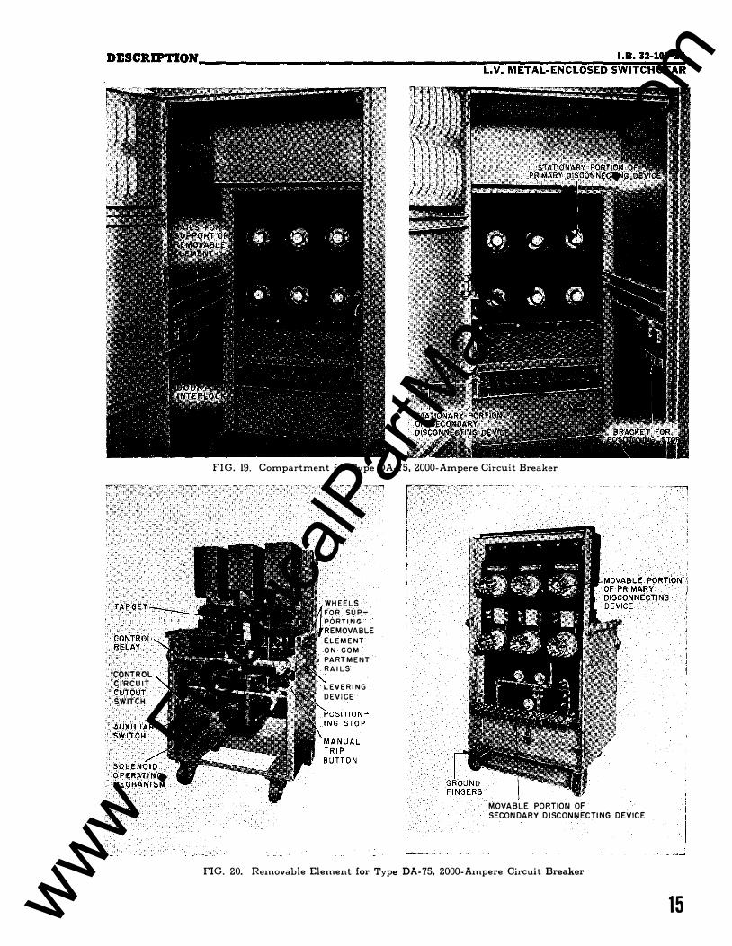
1 9 Compartment for Type DA-75, 2000-Ampere Circuit Breaker . . . . . . . . . . . . . . . 1 5
20 Removable Element for Type DA-75, 2000-Ampere Circuit Breaker. . . . . . . . . . 1 5
21 Automatic Shutters in a Type DA-1 00, 4000-Ampere Compartment-Open
Position . . . . . . . . . . . . . . . . . . . . . . . . . . . . . . . . . . . . . . . . . . . . . . . . . . . . . . . . . . . 1 6
22 Automatic Shutters in a Type DA-100 Compartment-Closed Position . . . . . . . . . 1 6
23 Removable Element for Type DA-100, 4000-Ampere Circuit Breaker . . . . . . . . . 1 6
24 Compartment for Type DA-100, 5000- or 6000-Ampere Circuit Breaker . . . . . . 1 7
25 Removable Element for Type DA-100, 5000- or 6000-Ampere Circuit Breaker . . 1 7
26 Metal-Enclosed Switchgear Partially Prepared for Shipment . . . . . . . . . . . . . . . . 1 9
27 Dimensions for Locating Stationary Structure . . . . . . . . . . . . . . . . . . . . . . . . . . . . . 20
28 Cable Clamping Block Arrangements. . . . . . . . . . . . . . . . . . . . . . . . . . . . . . . . . . . 21
3 www . El
ectric
alPar
tMan
uals
. com
4 www . El
ectric
alPar
tMan
uals
. com
I.B. 32-100-lA L.V. METAL-ENCLOSED SWITCHGEAR
Low-Voltage
METAL-ENCLOSED SWITC HGEAR
This instruction book has been prepared to familiarize the purchaser's
engineering and operating staff with the low-voltage (600 volts or lower)
metal-enclosed switchgear supplied by Westinghouse. The information con
tained herein should be carefully studied before attempting to install or operate
the equipment.
Proper installation, operation and maintenance are necessary to assure
continued satisfactory service from the equipment. It should not be installed
in places where it will be called upon to operate at voltages or currents greater
than those for which it was designed.
For instructions pertaining to a particular piece of apparatus supplied as
part of the switchgear equipment, refer to the instruction book or leaflet ap
plying to that particular type of apparatus. Copies of the applicable publica
tions are furnished along with this book for each switchgear installation .
•
Caution: Only authorized and properly trained personnel should
be permitted to operate or handle any portion of the switchgear.
5 www . El
ectric
alPar
tMan
uals
. com
6
FIG. 1. Front View of Indoor Metal-Enclosed Switchgear Containing Types DB-25 and DB-50 Circuit Breakers as Removable Elements
www . El
ectric
alPar
tMan
uals
. com
PART ONE 1.8. 32-100-lA L. V. METAL-ENCLOSED SWITCHGEAR
DESCRIPTION
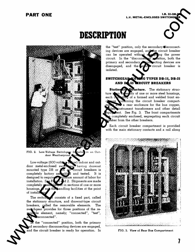
FIG. 2. Low-Voltage Switchgear Installed in an Outdoor Weatherproof Housing
Low-voltage (600 volts or below) indoor and outdoor metal-enclosed switchgear having drawout mounted type DB or DA air circuit breakers is completely factory assembled and tested. It is designed to require a minimum amount of labor for installation. See Figs. land 2. Shipments are made completely assembled, or in sections of one or more housings, to suit the handling facilities at the point of installation.
The switchgear consists of a fixed part, called the stationary structure, and drawout-type circuit breakers, called the removable elements. The switchgear provides for three positions of the removable element, namely; "connected", "test", and "disconnected".
In the "connected" position, both the primary and secondary disconnecting devices are engaged, and the circuit breaker is ready for operation. In
the "test" position, only the secondary disconnecting devices are engaged, and the circuit breaker can be operated without energizing the power circuit. In the "disconnected" position, both the primary and secondary disconnecting devices are disengaged, and the entire circuit breaker is isolated.
SWITCHGEAR HAVING TYPES DB-15, DB-ZS AND DB-50 CIRCUIT BREAKERS
Stationary Structure. The stationary structure is an assembly of one or more steel housings, each consisting of a formed and welded front enclosure containing the circuit breaker compartments and a rear enclosure for the bus copper, cables, instrument transformers and other detail equipment. See Fig. 3. The front compartments are completely enclosed, segregating each circuit breaker from the other breakers.
Each circuit breaker compartment is provided with the main stationary contacts and a rail along
FIG. 3. View of Rear Bus Compartment
1 www . El
ectric
alPar
tMan
uals
. com
DESCRIPTION---------------------------------------------------------
each side for supporting the removable element. These rails permit the removable element to be
moved between the "connected" and "discon
nected" positions, with a positive stop for each
position and by use of the rail extensions (for all
except the type DB-15), completely out of the com
partment.
The rear enclosure is made up of the rear frames,
tie members, top sheets and rear covers, all bolted
together and to the rear of the front compartment.
The rows or square holes which are punched in the rear frame, tie members and the rear flanges of the
front compartment permit changes and additions
to be made without cutting, welding or drilling.
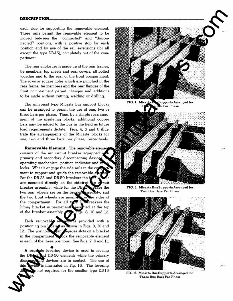
The universal type Micarta bus support blocks
can be arranged to permit the use of one, two or
three bars per phase. Thus, by a simple rearrangement of the insulating blocks, additional copper
bars may be added to the bus in the field as future
load requirements dictate. Figs. 4, 5 and 6 illustrate the arrangements of the Micarta blocks for
one, two and three bars per phase, respectively .
Removable Element. The removable element
consists of the air circuit breaker equipped with
primary and secondary disconnecting devices, an operating mechanism, position indicator and inter
locks. Wheels engage the side rails in the compartment to support and guide the removable element.
For the DB-25 and DB-50 breakers the four wheels
are mounted directly on the sides of the circuit breaker assembly, while for the DB-15 breaker the
two rear wheels are on the breaker assembly, and
the two front wheels are mounted on the sides of the compartment. For all type DB breakers the
lifting bracket is permanently mounted at the top of the breaker assembly. See Figs. 8, lO and 12.
Each removable element is provided with a
positioning pin located as shown in Figs. 8, lO and
12. The positioning pin engages slots on a bracket
in the compartment to lock the removable element
in each of the three positions. See Figs. 7, 9 and 11.
A separate levering device is used in moving
the DB-25 and DB-50 elements while the primary
disconnecting devices are in contact. The use of
this device is illustrated in Fig. 16. The levering
device is not required for the smaller type DB-15
breaker.
8
FIG. 4. Micarta Bus Supports Arranged for One Bus Bar Per Phase
FIG. 5. Micarta Bus Supports Arranged for Two Bus Bars Per Phase
FIG. 6. Micarta Bus Supports Arranged for Three Bus Bars Per Phase
www . El
ectric
alPar
tMan
uals
. com
DESCRIPTION __________________________________ ���������··�B�. 3�2�-1� 00�-�1 A L.V. METAL-ENCLOSED SWITCHGEAR
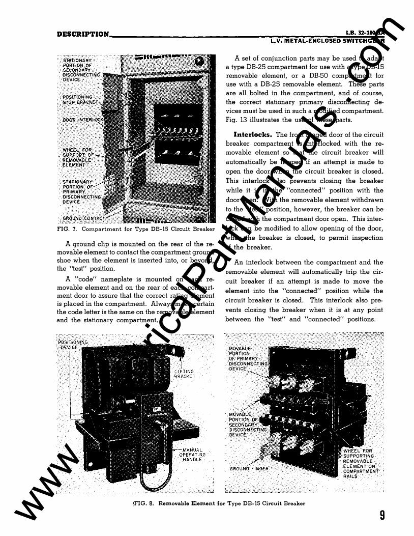
STATIONARY PORTION OF SECONDARY DISCONNECTING DEVICE
POSITIONING
STOP BRACKET
DOOR
WHEEl. FOR SUPPORT OF REMOVABI.E E L EMENT
STATIONARY PORTION PRIMARY DISCONNECTING DEVICE
FIG. 7. Compartment for Type DB-15 Circuit Breaker
A ground clip is mounted on the rear of the removable element to contact the compartment ground shoe when the element is inserted into, or beyond, the "test" position.
A "code" nameplate is mounted on each removable element and on the rear of each compartment door to assure that the correct rating element is placed in the compartment. Always make certain the code letter is the same on the removable element and the stationary compartment.
A set of conjunction parts may be used to adapt a type DB-25 compartment for use with a type DB-15
removable element, or a DB-50 compartment for use with a DB-25 removable element. These parts
are all bolted in the compartment, and of course,
the correct stationary primary disconnecting de
vices must be used in such a modified compartment.
Fig. 13 illustrates the use of these parts.
Interlocks. The front hinged door of the circuit
breaker compartment is interlocked with the re
movable element so that the circuit breaker will
automatically be tripped if an attempt is made to
open the door when the circuit breaker is closed.
This interlock also prevents closing the breaker
while it is in the "connected" position with the
door open. With the removable element withdrawn
to the "test" position, however, the breaker can be
closed with the compartment door open. This inter
lock can be modified to allow opening of the door,
when the breaker is closed, to permit inspection
of the breaker.
An interlock between the compartment and the
removable element will automatically trip the cir
cuit breaker if an attempt is made to move the
element into the "connected" position while the
circuit breaker is closed. This interlock also pre
vents closing the breaker when it is at any point
between the "test" and "connected" positions.
MOVABLE PORTION OF PRIMARY
DISCONNECTING DEVICE
E
PORTION OF
SECONDARY DISCONNECTING
·DEVICE
L FOR SUPPORTING
REMOVABLE ELEMENT ON COMPARTMENT RAILS
\FIG. 8. Removable Element for Type DB- 15 Circuit Breaker
9 www . El
ectric
alPar
tMan
uals
. com
DESCRIPTION ____________________________________________________ _
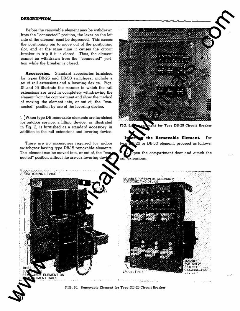
Before the removable element may be withdrawn from the "connected" position, the lever on the left side of the element must be depressed. This causes the positioning pin to move out of the positioning slot, and at the same time it causes the circuit breaker to trip if it is closed. Thus, the element cannot be withdrawn from the "connected" position while the breaker is closed.
Accessories. Standard accessories furnished for types DB-25 and DB-50 switchgear include a set of rail extensions and a levering device. Figs. 15 and 16 illustrate the manner in which the rail extensions are used in completely withdrawing the element from the compartment and show the method of moving the element into, or out of, the "connected" position by use of the levering device.
�-- �When type DB removable elements are furnished for outdoor service, a lifting device, as illustrated in Fig. 2, is furnished as a standard accessory in addition to the rail extensions and levering device.
There are no accessories required for indoor switchgear having type DB-15 removable elements. The element can be moved into, or out of, the "connected" position without the use of a levering device.
POSITIONING DEVICE .
r77;:::7£'""""""""-""'"'""-··----·--·· ......... ., ...... ..
1 !
WHEELS FOR
SUPP ORTING
REMOVABLE ELEMENT ON COMPARTMENT RAILS
FIG. 9. Compartment for Type DB-25 Circuit Breaker
Inserting the Removable Element. For
type DB-25 or DB-50 element, proceed as follows:
1 . Open the compartment door and attach the
rail extensions.
FIG. 10. Removable Element for Type DB-25 Circuit Breaker
10 www . El
ectric
alPar
tMan
uals
. com
DESCRIPTION __________________________________ �����������. B�- �32�-������A
L.V. METAL-ENCLOSED SWITCHGEAR
STATIONARY PORTiON OF SECONDARY
DtSCONNE.CTtNG DEVICE
STATIONARY PORTION PRIMARY DISCONNECTING DEVICE
DOOR INTER
RAILS SUPPORT OF REMOVABLE ELEMENT
!>ROUND CONTACT
FIG. 1 1 . Compartment for Type DB-50 Circuit Breaker
Z. Check the code nameplates on both the removable element and compartment door to see that they agree in code letter.
3. Lift the removable element and place it on the rail extensions.
4. Push the element into the compartment until the positioning pin drops into the first slot, thus holding the element in the "disconnected" position.
and push the element further into the compartment until the pin engages the second slot, holding the element in the "test" position.
7. Close and trip the circuit breaker, and check its operation in general. The circuit breaker is closed by rotating the operating handle in a clockwise direction and tripped by turning the handle in the opposite direction.
8. Release the positioning stop pin, and push the element into the compartment until the movable and stationary portions of the primary disconnecting devices start to engage.
9. Insert the levering device, and lift up on the handle until the removable element reaches the "connected" position. This will be noted when the two rear wheels strike the stops located in the cell' rails.
10. Remove the levering device. latch the compartment door.
Close and;
The method of inserting the type DB-15 removable element is similar, except that the element is lifted�
and placed directly on the compartment rails instead! of on rail extensions, and a levering device is not,
required to move the element between the "test"l and "connected" positions.
Removing the Element. For type DB-25 or DB-50 element, proceed as follows: lj
5. Remove the rail extensions. 1. Trip the circuit breaker, and open the com-partment door.
6. Release the positioning stop pin by depressing , . i ,, the lever on the left side of the removable element, -'1"1U Z. Insert the levering device handle.
WHEELS FOR SUPPORTING REMOVABLE ELEMENT ON RAILS IN COMPARTMENT.·
MOVABLE -..,_ .., PORTION OF SECONDARY DISCONNECTING
DEVICE
MOVABLE PORTION OF PRIMARY 01 SCONNECTI NG DEVICE
GROU ND FINGER
FIG. 12. Removable Element for Type DB-50 Circuit Breaker
11 www . El
ectric
alPar
tMan
uals
. com
DESCRIPTION-------------------------------------------------------
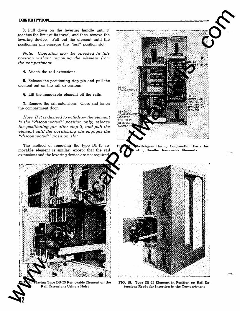
3. Pull down on the levering handle until it reaches the limit of its travel, and then remove the levering device. Pull out the element until the positioning pin engages the "test" position slot.
Note: Operation may be checked in this
position without removing the element from
the compartment.
4. Attach the rail extensions.
5. Release the positioning stop pin and pull the element out on the rail extensions.
6. Lift the removable element off the rails.
7. Remove the rail extensions. Close and fasten the compartment door.
Note: If it is desired to withdraw the element
to the "disconnected" position only, release
the positioning pin after step 3, and pull the
element until the positioning pin engages the
"disconnected" position slot.
The method of removing the type DB-15 removable element is similar, except that the rail extensions and the levering device are not required.
FIG. 14. Placing Type DB-25 Removable Element on the Rail Extensions Using a Hoist
12
DB-50 COMPARTMENT
DB-50 COMPARTMENT ADAPTED FOR DB-25 REMOVABLE
,ELEMENT
FIG. 13. Switchgear Having Conjunction Parts for Mounting Smaller Removable Elements
[ I
FIG. 15. Type DB-25 Element in Position on Rail Ex· tensions Ready for Insertion in the Compartment
www . El
ectric
alPar
tMan
uals
. com
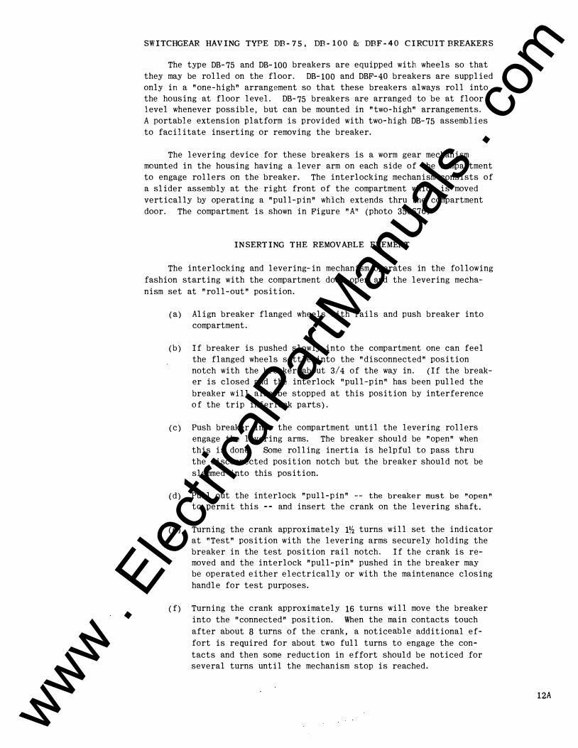
SWITCHGEAR HAVING TYPE DB-75, DB-100 & DBF-40 CIRCUIT BREAKERS
The type DB-75 and DB- 100 breakers are equipped with wheels so that
they may be rolled on the floor. DB-100 and DBF-40 breakers are supplied
only in a "one-high" arrangement so that these breakers always roll into
the housing at floor level. DB-75 breakers are arranged to be at floor level whenever possible, but can be mounted in "two-high" arrangements.
A portable extension platform is provided with two-high DB-75 assemblies
to facilitate inserting or removing the breaker.
The levering device for these breakers is a worm gear mechanism
mounted in the housing having a lever arm on each side of the compartment
to engage rollers on the breaker. The interlocking mechanism consists of
a slider assembly at the right front of the compartment which is moved
vertically by operating a "pull-pin" which extends thru the compartment
door. The compartment is shown in Figure "A" (photo 350676).
INSERTING THE REMOVABLE ELEMENT
The interlocking and levering-in mechanism operates in the following
fashion starting with the compartment door open and the levering mecha
nism set at "roll-out" position.
(a) Align breaker flanged wheels with rails and push breaker into
compartment.
(b) If breaker is pushed slowly into the compartment one can feel
the flanged wheels settle into the "disconnected" position
notch with the breaker about 3/4 of the way in. (If the break
er is closed and the interlock "pull-pin" has been pulled the
breaker will also be stopped at this position by interference
of the trip interlock parts).
(c) Push breaker into the compartment until the levering rollers
engage the levering arms. The breaker should be "open" when
this is done. Some rolling inertia is helpful to pass thru
the disconnected position notch but the breaker should not be
slammed into this position.
(d) Pull out the interlock "pull-pin" -- the breaker must be "open" to permit this -- and insert the crank on the levering shaft.
(e) Turning the crank approximately 1� turns will set the indicator
at "Test" position with the levering arms securely holding the
breaker in the test position rail notch. If the crank is removed and the interlock "pull-pin" pushed in the breaker may
be operated either electrically or with the maintenance closing
handle for test purposes.
(f) Turning the crank approximately 16 turns will move the breaker
into the "connected" position. When the main contacts touch
after about 8 turns of the crank, a noticeable additional ef
fort is required for about two full turns to engage the con
tacts and then some reduction in effort should be noticed for
several turns until the mechanism stop is reached.
12A www . El
ectric
alPar
tMan
uals
. com
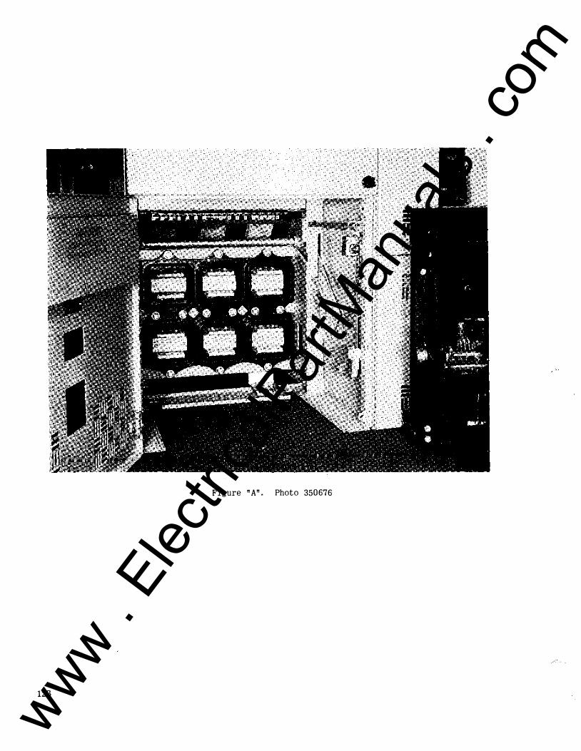
Figure "A". Photo 350676
128
www . El
ectric
alPar
tMan
uals
. com
( g) Remove the crank, close the door, secure the door latch knobs , and push i n the i nterlock " pull-p in" . A door i nterlock holds
the breaker trip-free until the door i s fully secured. Also
releas i ng the interlock latches the door on the ins ide -- if the interlock is released first then the door cannot be fully closed.
( h) To REMOVE the breaker the s implified procedure i s to:
(1) Trip breaker.
(2) Pull interlock " pull-p i n " . (3) Open door.
(4) Insert crank.
(5) Crank breaker out to " roll-out" pos ition.
(6) Pull breaker out of compartment.
The interlock p arts of the DB-75 are so designed that the interlock
cannot trip the breaker -- the breaker must be in the open position to
p erm it movement of the i nterlock .
A levering device position ind icator has been placed on the left
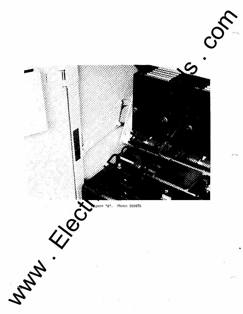
s ide of the compartment as shown in Figure "B" photo 350675. The test
pos i ti on i s established with the levering arms j ust securing the breaker
w ithout actually moving it horizontally -- this prevents the breaker " walk ing out" of the compartment when operated electrically. The roll
out and connected pos itions do not have indicating marks as they are e stabli shed by the limits of travel of the levering devi c e .
LUBRICATION
The levering dev ice should have rollers and bearings lubricated
w i th light machine o i l and the worm gear lightly coated w ith a medium
fibre grease.
The main disconnecting finger clusters and stationary contacts
should be cleaned periodically but KEPT DRY. Vaseline or grease should
NOT be applied to these contact surfaces as it w i ll hold d irt and p ar
t i cles of plating which w i ll cause an increase in the levering-i n force
required.
12C
www . El
ectric
alPar
tMan
uals
. com
-
Figure "B". Photo 350675
120
www . El
ectric
alPar
tMan
uals
. com
DESCRIPTION, __________________________________ ���������··�B�.3�2�- 1���1A L.V. METAL-ENCLOSED SWITCHGEAR
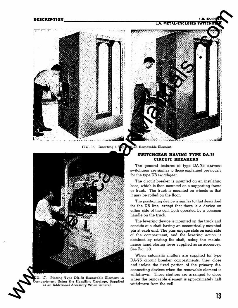
FIG. 16. Inserting a Type DB-25 Removable Element
fiG. p. Placing Type DB-50 Removable Element in Compartment Using the Handling Carriage, Supplied
as an Additional Accessory When Ordered
SWITCHGEAR HAVING TYPE DA-75 CIRCUIT BREAKERS
The general features of type DA-75 drawout switchgear are similar to those explained previously for the type DB switchgear.
The circuit breaker is mounted on an insulating base, which is then mounted on a supporting frame or truck. The truck is mounted on wheels so that it may be rolled on the floor.
The positioning device is similar to that described for the DB line, except that there is a device on either side of the cell, both operated by a common handle on the truck.
The levering device is mounted on the truck and consists of a shaft having an eccentrically mounted pin at each end. The pins engage slots on each side of the compartment, and the levering action is obtained by rotating the shaft, using the maintenance hand closing lever supplied as an accessory. See Fig. 1 8.
When automatic shutters are supplied for type DA-75 circuit breaker compartments, they close and isolate the fixed partion of the primary disconnecting devices when the removable element is withdrawn. These shutters are arranged to close when the removable element is approximately half withdrawn from the cell.
13 www . El
ectric
alPar
tMan
uals
. com
DESCRIPTION-------------------------------------------------------
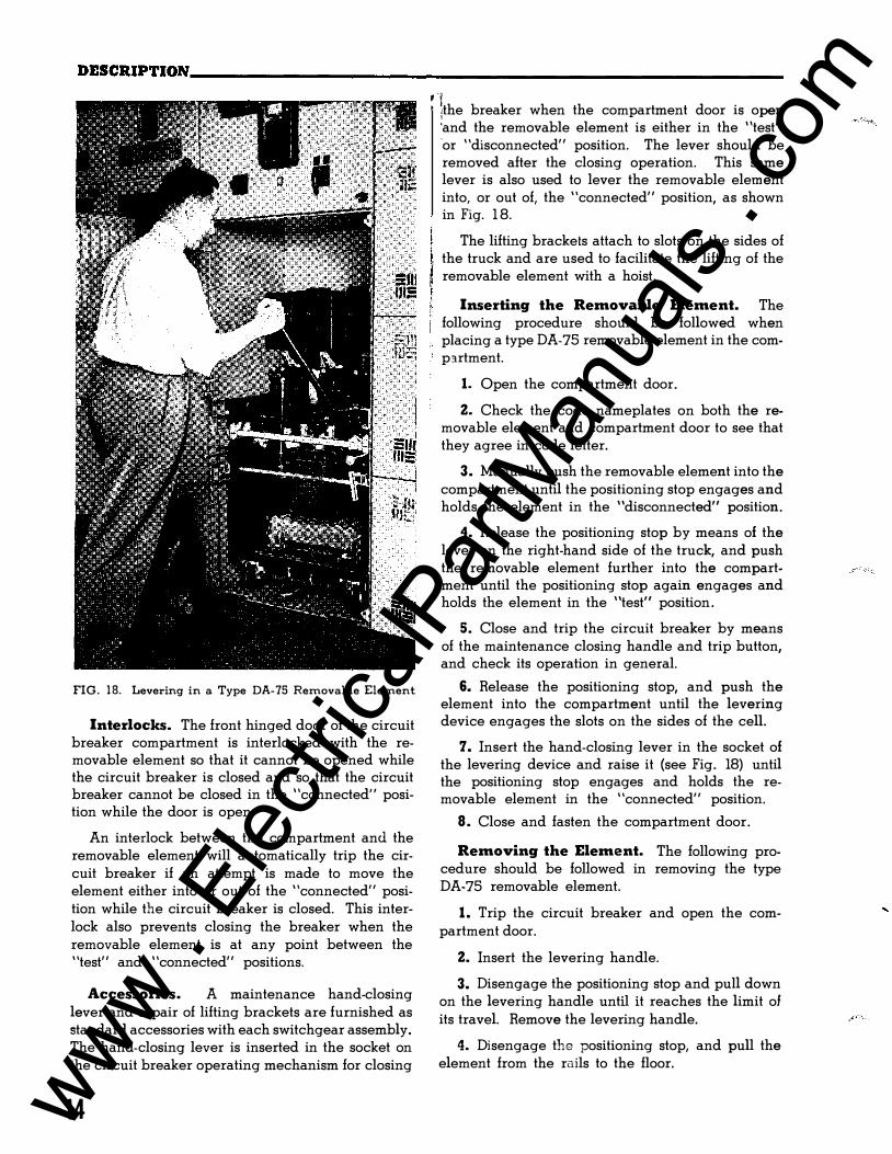
FIG. 18. Levering in a Type DA-75 Removable Element
Interlocks. The front hinged door of the circuit breaker compartment is interlocked with the removable element so that it cannot be opened while the circuit breaker is closed and so that the circuit breaker cannot be closed in the "connected" position while the door is open.
An interlock between the compartment ancl the removable element will automatically trip the circuit breaker if an attempt is made to move the element either into or out of the "connected" position while the circuit breaker is closed. This interlock also prevents closing the breaker when the removable element is at any point between the "test" and "connected" positions.
Accessories. A maintenance hand-closing lever and a pair of lifting brackets are furnished as standard accessories with each switchgear assembly. The hand-closing lever is inserted in the socket on the circuit breaker operating mechanism for closing
14
, l ' /the breaker when the compartment door is open
'and the removable element is either in the "test" 'or "disconnected" position. The lever should be removed after the closing operation. This same lever is also used to lever the removable element into, or out of, the "connected" position, as shown in Fig. 1 8.
The lifting brackets attach to slots on the sides of , the truck and are used to facilitate the lifting of the
removable element with a hoist.
Inserting the Removable Element. The following procedure should be followed when placing a type DA-75 removable element in the comp3.rtment.
1. Open the compartment door.
Z. Check the code nameplates on both the removable element and compartment door to see that they agree in code letter.
3. Manually push the removable element into the compartment until the positioning stop engages and holds the element in the "disconnected" position.
4. Release the positioning stop by means of the lever on the right-hand side of the truck, and push the removable element further into the compartment until the positioning stop again engages and holds the element in the "test" position.
S. Close and trip the circuit breaker by means of the maintenance closing handle and trip button, and check its operation in general.
6. Release the positioning stop, and push the element into the compartment until the levering device engages the slots on the sides of the cell.
7. Insert the hand-closing lever in the socket of the levering device and raise it (see Fig. 18) until the positioning stop engages and holds the removable element in the "connected" position.
8. Close and fasten the compartment door.
Removing the Element. The following procedure should be followed in removing the type DA-75 removable element.
1. Trip the circuit breaker and open the compartment door.
Z. Insert the levering handle.
3. Disengage the positioning stop and pull down on the levering handle until it reaches the limit of its travel. Remove the levering handle.
4. Disengage the positioning stop, and pull the element from the ruils to the floor.
www . El
ectric
alPar
tMan
uals
. com
DESCRIPTION __________________________________ ���������··�B�-��2�-����t A L.V. METAL-ENCLOSED SWITCHGEAR
TARGET
CONTROL CIRCUIT CUTOUT SWITCH
F I G . 19. Compartment for Type DA-75, 2000-Ampere Circuit Breaker
WHEELS FOR SUPPORTING
EMOVABLE ELEMENT ON COMPARTMENT RAILS
EVER I NG DEVICE
MOVABLE PORTION OF SECONDARY DISCONNECTING DEVICE
FIG. 20. Removable Element for Type DA-75, 2000- Ampere Circuit Breaker
15 www . El
ectric
alPar
tMan
uals
. com
DESCRIPTION1-----------------------------------------------------
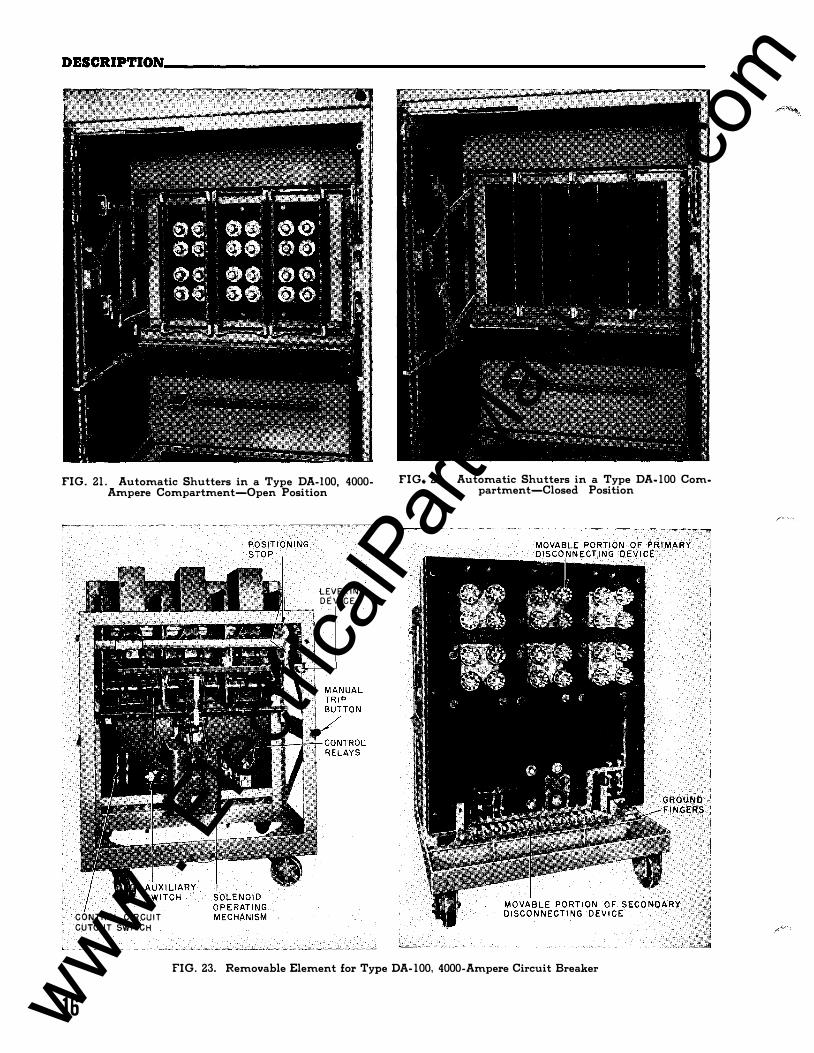
FIG. 21. Automatic Shutters in a Type DA-100, 4000-Ampere Compartment-Open Position
CONTROL CIRCUIT CUTOUT SWITCH
LEVERING DEVICE
FIG. 22. Automatic Shutters in a Type DA-100 Compartment-Closed Position
FIG. 23. Removable Element for Type DA-100, 4000-Ampere Circuit Breaker
16 www . El
ectric
alPar
tMan
uals
. com
DESCRIPTION __________________________________ ����������·-�B-�3�2�-1���1A L.V. METAL-ENCLOSED SWITCHGEAR
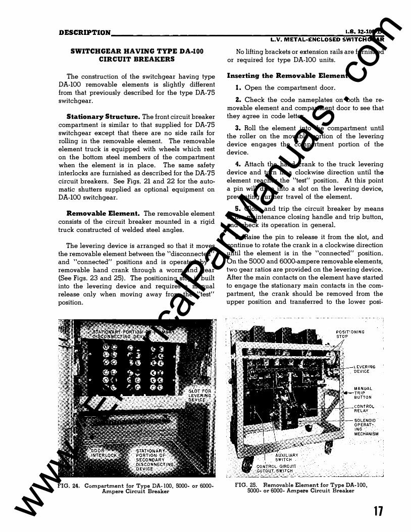
SWITCHGEAR HAVING TYPE DA-100 CIRCUIT BREAKERS
The construction of the switchgear having type DA-100 removable elements is slightly different from that previously described for the type DA-75 switchgear.
Stationary Structure. The front circuit breaker compartment is similar to that supplied for DA-75 switchgear except that there are no side rails for rolling in the removable element. The removable element truck is equipped with wheels which rest on the bottom steel members of the compartment when the element is in place. The same safety interlocks are furnished as described for the DA-75 circuit breakers. See Figs. 21 and 22 for the automatic shutters supplied as optional equipment on DA-100 switchgear.
Removable Element. The removable element consists of the circuit breaker mounted in a rigid truck constructed of welded steel angles.
The levering device is arranged so that it moves the removable element between the "disconnected" and "connected" positions and is operated by a removable hand crank through a worm and gear (See Figs. 23 and 25). The positioning stop is built into the levering device and requires a manual release only when moving away from the "test" position.
FIG. 24. Compartment for Type DA-100, 5000- or 6000-Ampere Circuit Breaker
No lifting brackets or extension rails are furnished or required for type DA-100 units.
Inserting the Removable Element
1. Open the compartment door.
2. Check the code nameplates on both the removable element and compartment door to see that they agree in code letter.
3. Roll the element into the compartment until the roller on the movable portion of the levering device engages the compartment portion of the device.
4. Attach the hand crank to the truck levering device and turn in a clockwise direction until the element reaches the "test" position. At this point a pin will drop into a slot on the levering device, preventing further travel of the element.
5. Close and trip the circuit breaker by means of the maintenance closing handle and trip button, and check its operation in general.
6. Raise the pin to release it from the slot, and continue to rotate the crank in a clockwise direction until the element is in the "connected" position. On the 5000 and 6000-ampere removable elements, two gear ratios are provided on the levering device. After the main contacts on the element have started to engage the stationary main contacts in the compartment, the crank should be removed from the upper position and transferred to the lower posi-
SOLENOID OPERAT· lNG MECHANISM
FIG. 25. Removable Element for Type DA-100, 5000- or 6000- Ampere Circuit Breaker
17 www . El
ectric
alPar
tMan
uals
. com
DESCRIPTION---------------------------------------------------------
tion. The crank is then rotated in a counter-clockwise direction until the element reaches the "connected" position. The higher gear ratio obtained with the crank in the lower position makes it easier to lever the element into the "connected" position.
7. Remove the hand crank. Close and fasten the compartment door.
Removing the Element
1. Trip the circuit breaker and open the compartment door.
18
2. Attach the hand crank and rotate counterclockwise until the levering device pin drops into the slot in the "test" position. (For the 5000 or 6000 ampere circuit breakers, the crank is first attached in the lower position and rotated in a clockwise direction until the main contacts are disengaged, after which the crank is transferred to the upper position and rotated in a counterclockwise direction.)
3. Raise the stop pin and continue to rotate the crank in a counter-clockwise direction until the element is in the "disconnected" position.
www . El
ectric
alPar
tMan
uals
. com
PART TWO I .B. 32-100-lA L.V. METAL-ENCLOSED SWITCHGEAR
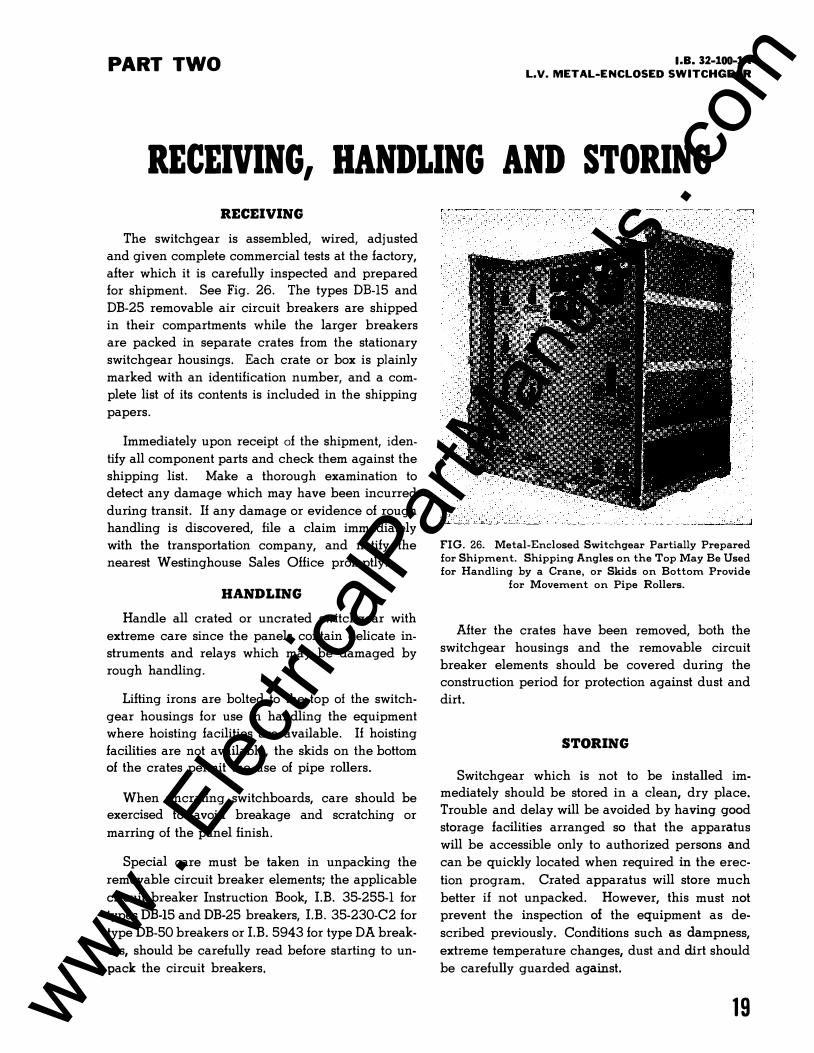
RECEIVING, HANDLING AND STORING RECEIVING
The switchgear is assembled, wired, adjusted
and given complete commercial tests at the factory,
after which it is carefully inspected and prepared
for shipment. See Fig. 26. The types DB-15 and
DB-25 removable air circuit breakers are shipped
in their compartments while the larger breakers
are packed in separate crates from the stationary
switchgear housings. Each crate or box is plainly
marked with an identification number, and a com
plete list of its contents is included in the shipping
papers.
Immediately upon receipt of the shipment, iden
tify all component parts and check them against the
shipping list. Make a thorough examination to
detect any damage which may have been incurred
during transit. If any damage or evidence of rough
handling is discovered, file a claim immediately
with the transportation company, and notify the
nearest Westinghouse Sales Office promptly.
HANDLING
Handle all crated or uncrated switchgear with
extreme care since the panels contain delicate in
struments and relays which may be damaged by
rough handling.
Lifting irons are bolted to the top of the switch
gear housings for use in handling the equipment
where hoisting facilities are available. If hoisting
facilities are not available, the skids on the bottom of the crates permit the use of pipe rollers.
When uncrating switchboards, care should be exercised to avoid breakage and scratching or
marring of the panel finish.
Special care must be taken in unpacking the
removable circuit breaker elements; the applicable
circuit breaker Instruction Book, LB. 35-255-1 for
types DB-15 and DB-25 breakers, LB. 35-230-C2 for
type DB-50 breakers or LB. 5943 for type DA break
ers, should be carefully read before starting to un
pack the circuit breakers.
FIG. 26. Metal-Enclosed Switchgear Partially Prepared for Shipment. Shipping Angles on the Top May Be Used for Handling by a Crane, or Skids on Bottom Provide
for Movement on Pipe Rollers.
After the crates have been removed, both the
switchgear housings and the removable circuit
breaker elements should be covered during the
construction period for protection against dust and
dirt.
STORING
Switchgear which is not to be installed immediately should be stored in a clean, dry place.
Trouble and delay will be avoided by having good
storage facilities arranged so that the apparatus
will be accessible only to authorized persons and
can be quickly located when required in the erec
tion program. Crated apparatus will store much
better if not unpacked. However, this must not
prevent the inspection of the equipment as de
scribed previously. Conditions such as dampness,
extreme temperature changes, dust and dirt should
be carefully guarded against.
19 www . El
ectric
alPar
tMan
uals
. com

PART THREE
INSTALLATION FOUNDATION
The switchgear is fabricated in welding jigs and
assembled on level steel bedplates and is kept
square and plumb at all times during erection and
adjustment. Since the tolerances and adjustments
are kept to a minimum, it must be installed on a
smooth level base to retain the easy operation of the
removable elements and the correct adjustments.
The preferred method of anchoring the indoor
switchgear is by fastening it to steel channels which
are embedded in the concrete floor. Floor plans
for drilling and locating this steel are supplied with
each contract. The top surfaces of the channels
must be smooth, level and flush with the finished
floor, and in the same plane.
Important: The surface of the floor be
tween the channels must not project above
the channels, and the floor in front of the
channels should not vary more than lfs inch
in any square yard and must not project
above the level of the floor steel.
Each housing is fastened to the floor channels
by either bolting or welding as shown in Fig. 27.
If bolting is to be used, the mounting bolts must be
placed in the floor steel before the concrete is
poured to assure that the tapped holes will not fill
with concrete. Welding is a quick and easy method
of securing the switchgear in place and eliminates
the layout of the mounting holes in the channels.
PLACING OF STATIONARY STRUCTURE
After the foundation is completed, the complete
switchgear assembly or section is set into place.
The assembly drawings furnished with the switch
gear should be referred to in making the installation.
If the structure has been shipped in more than two
sections, the center section should be placed in
position first and fastened down. The remaining
sections are then added progressively toward
20
� -16 TA P (4 H OLES) FOR BOLTING STEEl: WORK TO CHANNEL 1---+----
(STEEL WORK MAY I BE WELDED TO Nt''F======iF======:H· CHANN EL IF PREFERRED)
BKR. BKR. RA T. TYPE A .C.AMF' D.C. AMP.
15 15 DB-15 TO TO
225 225 35 35
DB-25 TO TO GOO 600 100 100
DB-50 TO TO 1600 1600 2000 2000
DA-75 2500 2500 3000 3000
4000 DA-100 4000 5000
6000
DA-100 5000 8000 6000 10000
DIM. A
16
20
26
30
48
60
SPACE FOR POWER a CONTROL CONDUITS
c--oo{l
DIM. DIM. DIM. B c D
.. 4B 30 36
48 271 8 36"
54 27� 44"
54 20� 8 44
66 21� 60
72 18� 8 70
"Must be 60 inches when handling carriage is furnished
FIG. 27. Dimensions for Locating Stationary Structure
either end, bolting them together and fastening
them to the floor steel. The lifting irons are re
moved from the top of each section after it is in
place.
POWER CONNECTIONS
When the switchgear consists of two or more
shipping sections, the main copper bus is neces
sarily disconnected between the shipping sections.
These bus connections should be completed first,
with particular attention to the pressure between
the contact surfaces. It is essential that the con
nections be securely bolted, since the conductivity
of the joint is proportional to the applied pressure
rather than to the area.
www . El
ectric
alPar
tMan
uals
. com
INSTALLATION __________________________________ ������
----�I .B=-� 3=��1=00�- l= A
L.V. METAL-ENCLOSED SWITCHGEAR
CABLE
'c=. --
CLEATS FOR 1!16 TO 1!11 /0 CABLE
CLEATS FOR ll11 /0 TO 1000 MCM CABLE
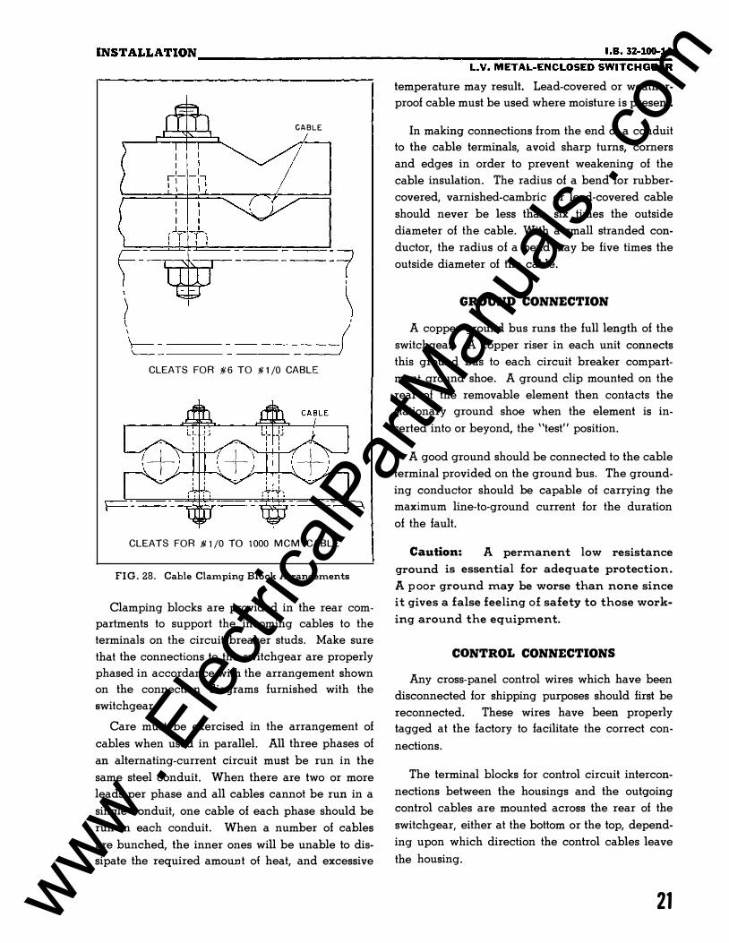
FIG. 28. Cable Clamping Block Arrangements
Clamping blocks are provided in the rear com
partments to support the incoming cables to the
terminals on the circuit breaker studs. Make sure
that the connections to the switchgear are properly
phased in accordance with the arrangement shown
on the connection diagrams furnished with the
switchgear.
Care must be exercised in the arrangement of
cables when used in parallel. All three phases of
an alternating-current circuit must be run in the
same steel conduit. When there are two or more
leads per phase and all cables cannot be run in a
single conduit, one cable of each phase should be
run in each conduit. When a number of cables
are bunched, the inner ones will be unable to dis
sipate the required amount of heat, and excessive
temperature may result. Lead-covered or weather
proof cable must be used where moisture is present.
In making connections from the end of a conduit
to the cable terminals, avoid sharp turns, corners
and edges in order to prevent weakening of the
cable insulation. The radius of a bend for rubber
covered, varnished-cambric or lead-covered cable
should never be less than six times the outside
diameter of the cable. With a small stranded con
ductor, the radius of a bend may be five times the
outside diameter of the cable.
GROUND CONNECTION
A copper ground bus runs the full length of the
switchgear. A copper riser in each unit connects
this ground bus to each circuit breaker compart
ment ground shoe. A ground clip mounted on the
rear of the removable element then contacts the
stationary ground shoe when the element is in
serted into or beyond, the "test" position.
A good ground should be connected to the cable
terminal provided on the ground bus. The ground
ing conductor should be capable of carrying the
maximum line-to-ground current for the duration
of the fault.
Caution: A permanent low resistance
ground is essential for adequate protection.
A p oor ground may be worse than none since
it gives a false feeling of safety to those work
ing around the equipment.
CONTROL CONNECTIONS
Any cross-panel control wires which have been
disconnected for shipping purposes should first be
reconnected. These wires have been properly
tagged at the factory to facilitate the correct con
nections.
The terminal blocks for control circuit intercon
nections between the housings and the outgoing
control cables are mounted across the rear of the
switchgear, either at the bottom or the top, depend
ing upon which direction the control cables leave
the housing.
21 www . El
ectric
alPar
tMan
uals
. com
INSTALLATION------------------------------------------------------
Relays designed to use movable armatures or
rotating discs have these parts tied or blocked before
shipment to protect them against possible damage
in transit. Remove all ties and blocking from the
relay armatures or discs after the switchgear is
installed and before control energy is applied.
The connections between the control wiring in
the switchgear and any remote equipment must be
of adequate size. The size of conductor required
will depend upon the distance and amount of cur
rent to be carried. When selecting wire or cable
sizes for instrument transformer circuits, the losses
in the conductor should be calculated and a check
made to assure that the combination of instrument
load and conductor losses does not exceed the
capacity of the transformer.
For electrically-operated breakers, it is important
that the voltage drop in the supply circuit be
checked to assure proper operation. This is espe
cially true where a low voltage trip source is used.
See NEMA air circuit breaker standards for the
range of control voltages at the terminals of the
operating mechanism.
The outside covering of control circuit connec
tions will depend on local conditions. If they are to
be installed in a dry place, braid-covered cable
will be satisfactory. If moisture is present, the cable
will require either a lead sheath or a weatherproof
covering.
Make sure that the polarity of the connections
from d-e control sources is correct. The polarity
is shown on the connection diagram.
When connecting external cables to the terminal
blocks on the switchgear, exercise care to assure
that the connections are properly made.
PRE-OPERATION CHECKS
After the switchgear equipment and apparatus
to be controlled have been installed and all inter
connections made, the equipment should be tested
and given a final check before being placed in
service. This is necessary to assure that the equip
ment has been correctly installed and that all con
nections are complete and have been properly
made.
22
Caution: Extreme care must be exercised
to prevent the equipment from being con
nected to the power system while the prelimi
nary tests are being conducted. If disconnect
ing switches are not available, line leads
should be disconnected to accomplish this.
The testing equipment required will depend
entirely on the type of installation. Portable volt
meters, both a-c and d-e, with a wide range of
scales, will usually be required. If the equipment
to be put into service is quite extensive and com
plicated, both a-c and d-e ammeters should be
available in case unexpected trouble develops.
Some simple portable device for ringing or
lighting out circuits should be included in the test
ing equipment. A convenient method for the latter
is to add a solid contact point to the lens end of
a flashlight. At some other convenient place on the
flashlight add a binding post. The battery and lamp
should be connected in series between the contact
point and the binding post. One end of a flexible
wire, four or five feet in length, can be attached to
the binding post and the other end provided with
a spring clip for quick attachment to the point to be
tested. Touching the contact point at the other end
of the circuit whose continuity is being checked
should complete the circuit through the lamp.
Lighting of the lamp will indicate that the circuit
is intact.
Although the inspection and tests given the
switching equipment at the factory assure that all
the connections on the switchboard are correct
and in good order, they should be examined to make
sure that they have not been loosened or damaged
during shipment or installation. Tighten all bolted
connections and joints to assure good contact.
Ring or light out the connections to the equip
ment apart from the switchboard, such as instru
ment transformers, circuit breaker operating mecha
nisms and auxiliary switches to make sure they are
correct. The extent to which this will have to be
done depends on the thoroughness of the installa
tion work.
www . El
ectric
alPar
tMan
uals
. com
INSTALLATION __________________________________ ���������·�-B�·�3�2-�1�00�-1 L.V. METAL-ENCLOSED SWITCHGEAR
Important: There must be definite assur
ance that all connections are correct before
an attempt is made to operate the equipment.
Before applying control energy, check all con
trol circuits, except current and potential trans
former secondary circuits, for grounds, and make
sure that all circuits are clear.
In order to show up any errors in the installation,
try out the different parts by putting current through
them at reduced voltage. Continue this procedure
progressively until all parts have been proved.
Remedy any incorrect operations during the trial
period.
Carefully store the covers for instruments, meters,
relays and other devices which have to be removed
d1uing the course of installation and test. Since
these are made either partly or entirely of glass,
they may be broken if not properly protected. If
anything temporarily stops the test work, such as
the end of the working day, replace all covers to
keep dust and dirt from collecting on the vital parts
of the equipment.
Any protective relays included with the equip
ment have been tested for correct connection and
operation at the factory, but the settings of the relays
for current, voltage or other quantities must be
made by the purchaser in accordance with his
standard practices to coordinate with the other
portions of his system. Study carefully the appli
cable relay instruction leaflets, supplied with the
switchgear equipment, before attempting to set the
relays.
23 www . El
ectric
alPar
tMan
uals
. com
PART FOUR
INSPECTION AND MAINTENANCE In order to obtain satisfactory service from the
switchgear, it must have proper inspection and
maintenance regularly.
The intervals between the inspections will be
determined by the operating and atmospheric con
ditions. Where dust is rapidly deposited within the
switchgear, especially if it is abrasive or has a high
conductivity, or where condensation occurs within
the switchgear, the inspection and cleaning should
be frequent.
The inspection must be done by experienced
personnel and should cover all the devices and
connections. Inspectors should be thoroughly in
structed and experienced in both the function and
adjustment of the various devices and should have
a uniform method of making the inspection. Good
results can very o.!ten be obtained by furnishing
the inspectors with detailed lists covering points
which need to be checked and reported at stated
intervals. Prints of all drawings and copies of all
instruction books, cards and leaflets should be
readily available in case of trouble; the mainte
nance personnel can refer to them for such detailed
information as may be required to correct the situa
tion.
Extreme care must be exercised that no circuits
are shorted or grounded and that the inspector
experiences no personal harm. Correct any defect
which is discovered, immediately.
Caution: Do not work around live parts
except in extreme emergencies. If work must
be performed on live equipment , take every
possible precaution to guard against acci
dents. Tools should be insulated, and rubber
gloves and insulating mats should be pro
vided.
Consider all connections live until the men
expecting to work on them assure themselves per-
24
sonally that the circuits are dead, and every pos
sible precaution should be taken to see that there
is no chance of a circuit being energized while
the men are working on it. Lock or block open
and place a suitable warning on switches which
have been opened to de-energize equipment for
maintenance purposes. In low-voltage metal-en
closed drawout switchgear, the removable ele
ments can be readily withdrawn to the "test" or
the "disconnected" position in which the primary
circuits are dead.
Caution: Do not touch a circuit breaker
under any circumstances when the removable
element is in the "connected" position. Some
of the exposed parts may he live even though
the breaker is open.
Keep the premises, particularly the switchgear
room, clean. Compressed air or a hand bellows
may be used to remove dust from the interior of the
switchgear and from the removable elements. Use
an air hose equipped with an insulating nozzle to
prevent contact with live circuits, and filter the air.
Remove dirt which cannot be blown from the insu
lating surfaces with a cloth saturated with *West
inghouse Electric Corporation Solvent Material No.
1609-1, obtainable through any Westinghouse En
gineering and Service Office. (When this solvent
is not available, Stoddard Solvent or cleaner's naph
tha can be used). Do not use abrasive material for
cleaning silverplated surfaces since the plating will
be removed, leaving the base material unprotected.
The exterior of the switchgear may be cleaned by
wiping with a chamois skin which has been im
mersed in luke warm water and wrung partially dry.
Before attempting inspection, maintenance or
adjustment of any devices such as circuit breakers,
relays, meters or instruments, read carefully the
instruction book covering the particular device.
www . El
ectric
alPar
tMan
uals
. com
SUP P L EMENT NO. l t . B . 32- 1 00- lA
SU PPLEMENTARY I NST RUCT I ON S
L O W V O L T A G E M E T A L E N C L O S E D S W I T C H G E A R T H R E E P O S I T I O N D R A W O U T T Y P E
STAT I ON A R Y STRU CTU R E
The stationary structure for three pos ition drawout c i rcuit breakers d iffers from the
structure for s ingle po si tion drawout c ircuit breakers as described in I. B. -32- 100- 1 in the
fo llowing respects :
1. The c ircuit breaker compartment doors may be closed and latched with the c ircuit
breaker in e i ther the connected , test, or d i sconnected po s i tion . (Page 7 of
I. B. 32 - 100 - 1 gives a complete description of connected, test and d i sconnected po
sitions) . The d i stance the c i rcuit breaker operating mechanism extends through the
opening in the compartment door (Fig. 1) provides a v i sual indication of whi ch po
s ition the breaker is occupy ing.
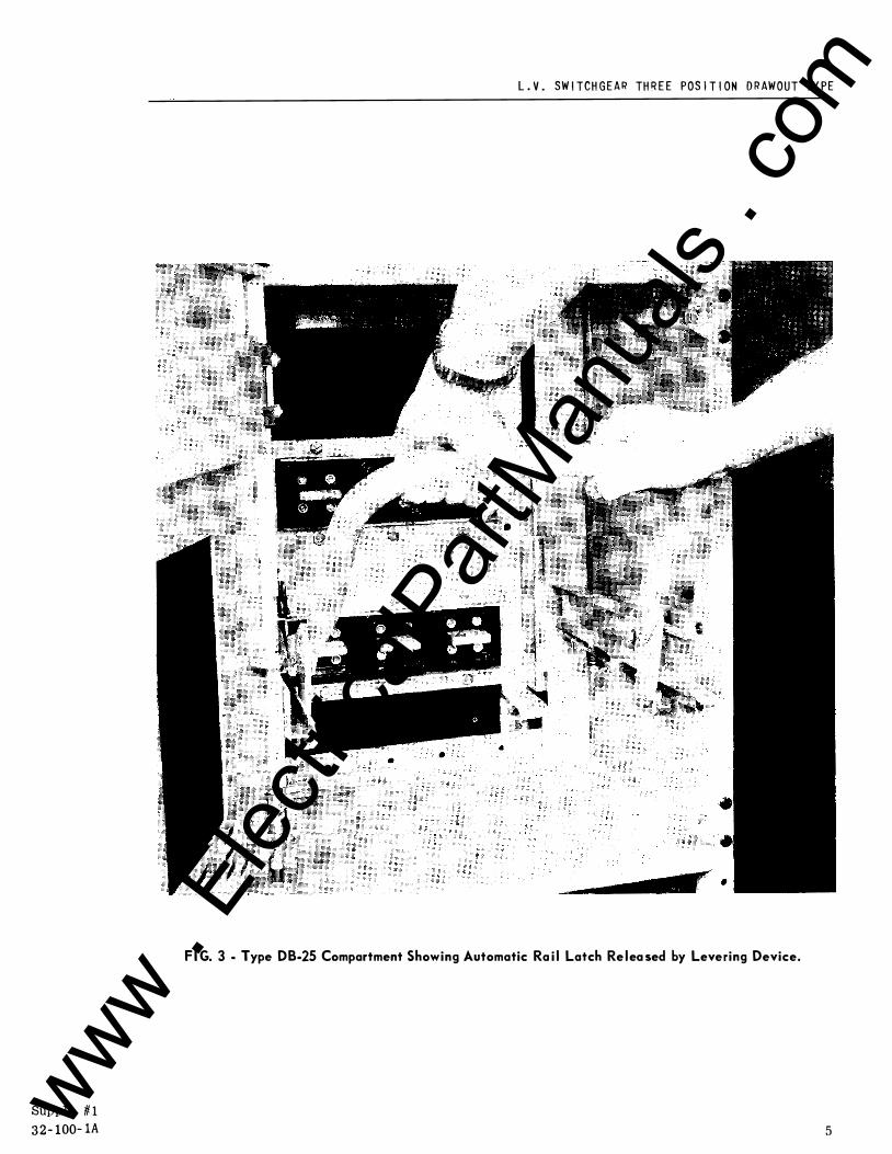
2. Type DB-50 and type DB-25 compartments have a latch o n the right hand rai l which
secures the c i rcuit breaker i n the connected position. This latch is automatically released by inserting the levering dev i c e into the compartment preparatory to with
drawing the c i rcuit breaker. (See page 11 of I. B. 32 - 100- 1 for operation of lever
ing device) . Fig. 2 for type DB-50 and Fig. 3 for type DB-25 compartments show the
levering dev i c e in position for mov i ng the c i rcuit breaker in or o ut of connected
pos ition and i llustrate the manner in which the latch is released. ( The c i rcuit
breaker element has been omitted in Fig. 2 and Fig. 3 to permit a better v i ew of
latch details) .
C A UT I ON : T h e a u t omat i c ra i l l at c h i s i n a d d i t i on t o t h e p o s i t i on i n g p i n on t he l e f t
s i d e o f t h e b reak e r e l em e n t . The l at t e r m u st s t i l l be o p e rated man u a l l y a s d e sc r i bed on p a g e
1 0 of I . B . 3 2 - 1 00 - 1 .
R EMO V A B LE E LEM ENTS
The type DB- 15 , DB-25 , DB-50, DB- 75 and DB-100 c ircuit breakers for three pos ition draw
out mounting d i ffer from the single pos ition drawout mounting c i rcuit breakers described in
I. B. 32- 100- 1 , I. B. 33 - 850- 1 & 2 , I. B . 35-230-C3 and I. B. 33 - 850-4 & 5 in the following re
spects :
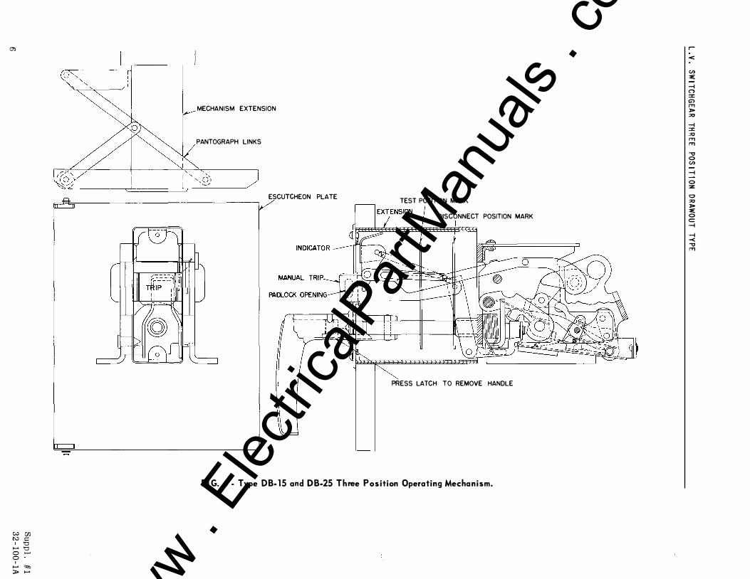
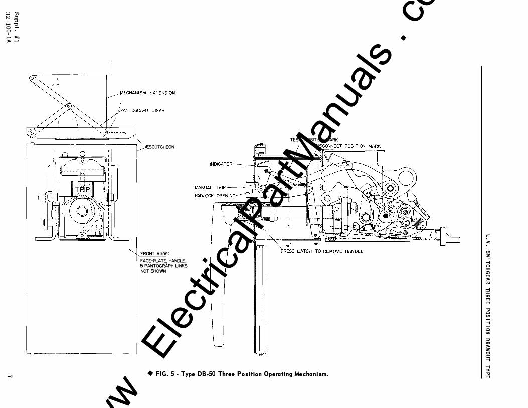
I . O p e rat i n g Mechan i sm - T y p e D B - 1 5 , D B -2 5 , F i g . � and T y p e D B - 5 0 F i g . 5 ,
A rectangular extens ion i s welded to the front o f the operating mechan i sm , enclo s ing a
lo nger handle shaft , close-open ind icator assembly , and push button hand trip details . The
removable operating handle is not used for manual tripping and is not supplied with electri
cally operated breakers .
W E S T I N G H O U S E E L E C T R I C ASSEMBL E D SWITCHGEAR D E V ICES
EAST P I TTSBU R GH P LANT •
NOVEMBE R, 1 958 C 0 R P 0 R A T I 0 N
E AST P I T TS BU RGH, PA.
www . El
ectric
alPar
tMan
uals
. com
L . V . SW I T C H G E A R T H R E E PO S I T I ON D RAWOUT TYPE
tt m:m:m:rn EIIIEUIEIJ I:
..
0 m:nr:II IEIU EIIIEIII:III :E
..
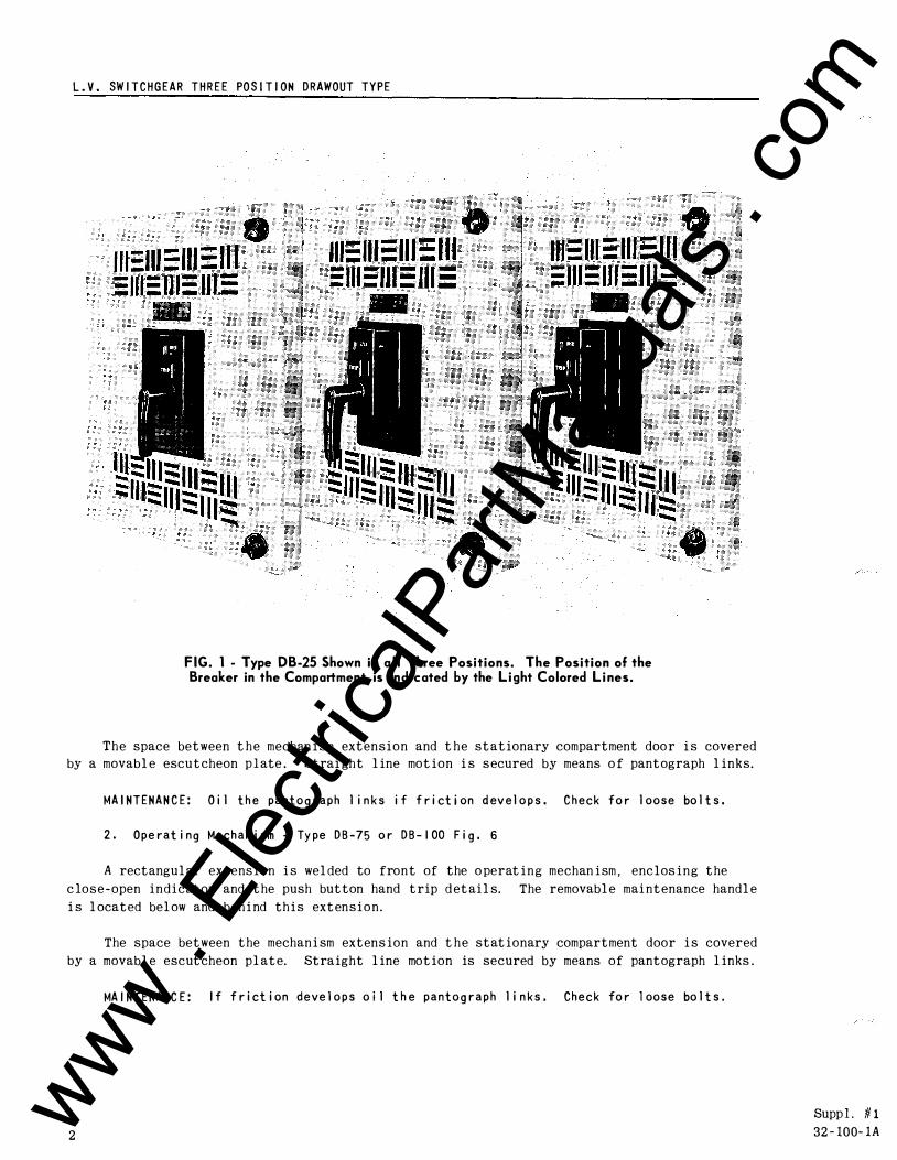
F IG. 1 - Type DB-25 Shown i n a l l Three Positions. The Position of the Breaker in the Compartment is Indicated by the L i ght Colored L i nes.
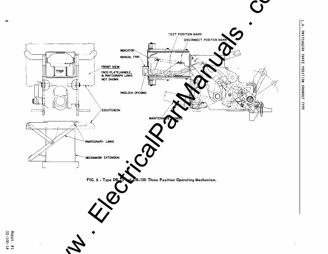
The space between the mechan i sm extension and the stationary compartment door i s covered
by a movable escutcheon p l ate . Strai ght line motion i s s ecured by means of pantograph links.
MA I N T E N A N C E : O i l t h e pan t o g r a p h l i n k s i f f r i ct i on d ev e l o p s . C h eck fo r l oo s e bo l t s .
2 . O p e rat i n g M e c h a n i sm - Ty pe D B -75 o r D B - 1 00 F i g . 6
A rectangular extens ion i s welded to front of the o perating mechan i sm , enclos ing the
close-open indicator and the push button hand trip d etails. The removable mai ntenance handle
i s located below and beh i nd th i s extension.
The space between the mechan i sm extens ion and the stationary compartment door i s covered
by a movable escutcheon plate. Straight line motion is secured by means of pantograph links .
2
MA I N T E N A N C E : I f f r i ct i on d e ve l o p s o i l t h e p a n t o g r a p h l i n k s . C h e c k fo r l oo s e bo l t s .
Supp l . '# 1 32 - 100- lA www .
Elec
tricalP
artM
anua
ls . c
om
Suppl . # 1
3 2 - 1 00 - 1A
L . V . SW I TC H G E A R TH R E E POS I T I O N D R AWOUT TYPE
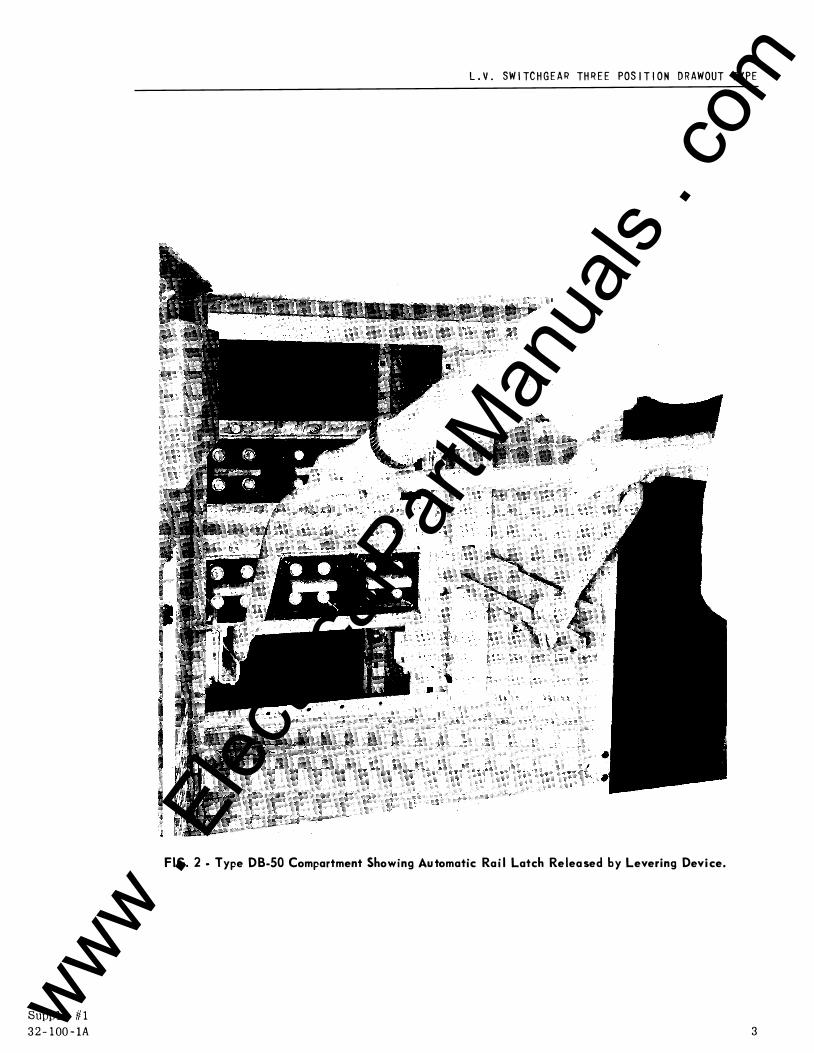
FIG. 2 · Type DB-50 Compartment Showing Au tomatic Ra i l Latch Re lea sed by Levering Devi ce.
3 www . El
ectric
alPar
tMan
uals
. com
4
L . V . SW I TC H G EA R TH R E E POS I T I ON D RAWOUT TY P E
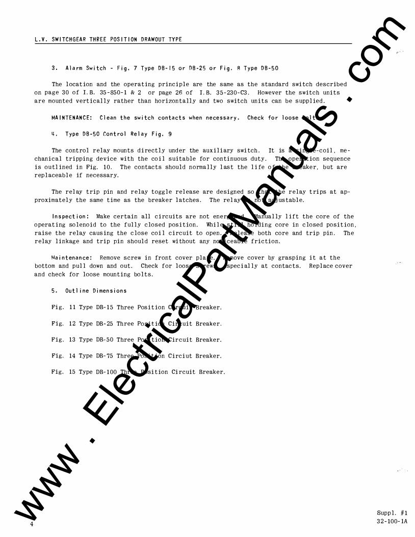
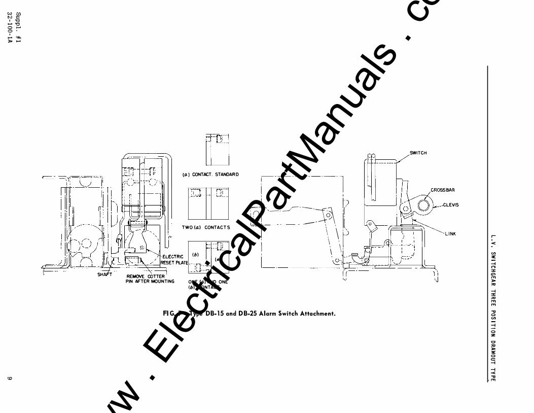
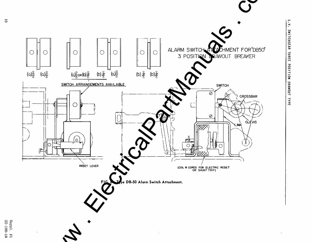
3 . A l a rm Sw i t c h - F i g . 7 T y p e D B - 1 5 o r O B - 2 5 o r F i g . R T y p e D B - 5 0
The l ocat ion and the operat ing princ i p l e are the same as the standard swi tch described
on page 3 0 o f L B. 35 - 850- 1 & 2 or page 2 6 o f L B. 3 5 - 23 0 - C3 . However the switch un i t s
a r e mounted vert ical ly rather than ho rizon t a l l y and two switch un i t s can b e s upp l ied .
MA I N T E N A N C E : C l ean t h e sw i t c h c o n t a c t s when n e ce s s a r y . C h e c k fo r l oo s e bo l t s .
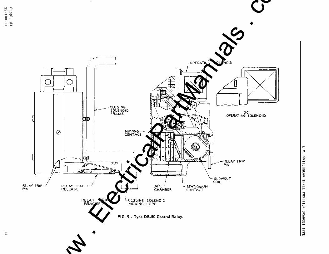
� . T y p e D B - 5 0 Co n t ro l Re l a y F i g . 9
The cont ro l r e l ay mounts d i rect l y und er the aux i l i ary swi tch . It is a single-coi l , me
chan i c a l t r i pping device with the co i l suitable fo r conti nuous duty . The operat ion sequence
i s outl ined i n Fig. 1 0 . The contacts shou l d norma l ly l as t the l i fe o f the breake r , but are
r ep l aceab l e if necessary.
The rel ay t rip pin and r e l ay togg l e rel ease are designed so that the r e l ay t ri ps at ap
proximately the same t ime as the break e r l atches . The re l ay is no t adj us tab l e.
I n s pect i on : Make certain all c i rcuits are not en e rg ized. Manua l ly l i ft the core of the
o perat i ng so l eno id to the ful ly c losed pos i t ion . Wh i l e s t i l l ho l d i n g core in c lo sed po s i t ion ,
raise the relay caus ing the c lose co i l c i rcuit to open . R e l ease both co re and trip pin . Th e
relay l i nkage and trip pin shoul d reset wi thout any no t iceab l e friction.
Ma i n t en a n ce : Remove screw i n front cover plate. Remove cover by grasp ing i t at the
bottom and pul l down and out . Check for loose sc rews , espec i al ly at contacts. Rep l ace cover
and check fo r loose mount ing bo l t s .
5 . Ou t l i n e D i men s i o n s
Fi g . 1 1 Type DB- 1 5 Three Pos i t ion C i rcuit Breaker.
F i g. 1 2 Type DB- 25 Th ree Po s i t ion Circuit Break e r .
F i g . 1 3 Type DB- 5 0 Three Pos i t ion Circuit Breaker.
Fig. 14 Type DB- 75 Three Pos i t ion C i rc i ut Breaker.
Fig. 15 Type DB- 1 00 Three Posi t ion Ci rcuit Breaker.
Supp l . tl- 1
3 2 - 100- lA www . El
ectric
alPar
tMan
uals
. com
Sup pl. # 1
32- 100- lA
L . V . SW I TCH G E A R TH R E E POS I T I ON D R AWOUT TY P E
- ·
F I G. 3 · Type DB-25 Compartment Showing Automatic Ra i l Latch Re l ea sed by Levering Device.
5 www . El
ectric
alPar
tMan
uals
. com
m
w [fJ t..:J c: I '0
,_. '0 0 ...... 0
I ,_. """' >- ,_.
MECHANISM EXTENSION
PANTOGRAPH LINKS
'-, ',0�)
ESCUTCHEON PLATE TEST POSITION MARK
DISCONNECT POSITION MARK
PRESS LATCH TO REMOVE HANDLE
FI G. 4 - Type DB- 15 and D B-25 T h ree Pos ition Operating Mecha n i sm.
r
<
U> :IE:
-i ("') :I: Ci) f"T'I ]> ;;o
-i :I: -"' f"T'I f"T'I
-o 0 U>
-i
0 :z
0 ;o ]> :IE: 0 c:: -i
-i -< -o f"T'I
www . El
ectric
alPar
tMan
uals
. com
w r:n N = I '0 ..... oo 0 ,...... 0
I ..... � :... .....
...::J
r"---- --
1 SCUTCHEON
l I "'+FRONT VIEW : · FACE-PLATE, HANDLE,
S PANTOGRAPH LINKS NOT SHOWN
TEST POSITION MARK
l....,_ _,-------- ------ ---�
FI G. 5 · Type DB-50 Th ree Po sition Operating Mechani sm.
r
<
en ::e:
-1 (") :::>:: G> I'T1 )> "' -1 :::>:: "' I'T1 I'T1 ...., 0 en
-1
0 :z
0 "' )> ::e: 0 c: -1
-1 -< ...., I'T1
www . El
ectric
alPar
tMan
uals
. com
0)
W Ul "" 1:: 1 '0 ,_. '0 0 ...... 0
I ...... '*' > ......
MANUAL I FRONT VIEW: �.J FACE-PLATE,HANOLE, 6 PANTOGRAPH LINKS
NOT SHOWN
PADLOCK
ESCUTCHEON
T E S T ITION MARK
POSITION MARK
7 MAINTENANCE HANDLE
F I G. 6 · Type DB-75 and D B- 1 00 Three Pos ition Operating Mechan ism.
r
<
(I) :e:
--i C"') :::t: G> ,., )> ::0
--i :::t: :0 ,., ,., -o 0 (I)
--i
0 ::z
0 ::0 )> :e: 0 c:: --i
--i -< -o ,.,
www . El
ectric
alPar
tMan
uals
. com
w (/) I:V C 1 '0 1-' '0 0 1-' 0 I ...... """' > ......
co
REMOVE COTTER
� lLJ (0. ) CONTACT. STANDAR D
"t;"7-t�t+-:;� .c'.J�-J- - +-"b.,l�--
TWO (0.) CONTACT S
.:! = =�}��--(b)
(4) --;il-'l:-r-.t-=
PIN AFTER MOUNTING ONE (a) AND ONE (b) CONTACT
�-�---�----l �i � - --- �/ · n · ' - - �· -1� l.r I . · J o'· I
· U :.; , bfl--- � -- - ' ' il I \ \ , )
SWITCH
1 \ . r I \ \ 0 L _ _ _ _ _ _ _ ·��� 11, / l
( ( '-J
Fl G. 7 · Type DB- 1 5 and D B-25 Alarm Switch Attachment.
CLEVIS
r
<
(I) ::E:
--t 0 :::z: C> ,..., > ::0
--t :::z: ::0 ,..., ,..., .., 0 (I)
--t
0 :z
<::I ::00 > ::E: 0 c: --t
--t -< .., ,...,
www . El
ectric
alPar
tMan
uals
. com
.... 0
W UJ "' c 1 '0 .... '0 0 ...... 0 I .... "1k ;J> ,_.
0 I I 0
(� (Q)�
0 O l i O O l i O ALARM SWITCH ATTACHMENT F OR11DB50
11
3 POSI TION DRAWOUT BREAKER
(�oR(b)f (b)� (Q� (b) � (b)� I
SWITCH ARRANGEMENTS AVA ILABLE SWITCH
----"<---------
RESET LEVER
r-1. ·-·-·-·-·{[1�-·-�·=.=--;..:v-· \A� CROSSBAR . � i
�' ,�. I r-·-. " 1 nf'-- ·-·
. •:;� · :�
��---- - -�y \ �: CLEVIS "�\_ I I ut � _ . L-------�� �· -( ,.-·-·-;-·---· ·�, \
(1)\ (�·) -�·
(COIL 8 CORES FOR ELECTRIC RESET OR SHUNT TRI P )
F I G. 8 · Type D B-50 Alarm Switch Attachment.
'
<
en :e:
-1 C"> :::t: Q m )> ;;o
-1 :::t: ;;o m m
.., 0 en
-1
0 :z
0 ;;o )> :e: 0 c: -1
-1 -< .., m
www . El
ectric
alPar
tMan
uals
. com
w Ul tv c I '0 1-' '0 0 ,_. o ·
I ...... ""' ;x,. ......
...... ......
RELJ'I.Y TRI P PI N
0
� -------, ' ? _ _ ____)
I
�CLOS I NG SOLENO I D FRAME.
M OVING CON TACT
\ I - -Y �'I' -.l . l
R E L AY TO GGLE__/ Jt I R E L EASE �
R E LA Y T R I P CLO S I N G BRAC K E T MOVI NG
ARC C H AM BER
S O L E.N O I D CORE
F I G. 9 • Type D B-50 Control Re l ay.
A. C. OPERATI N G S O L E N O I D
STAT I O NARY C O N TACT
D.C. OPERAT ING SOLEN O I D
RELAY TRIP PI N
B LOWOUT C O I L
'
<
U> ::e:
-i n ::t: G> ,.,., l> ;o
-i ::t: ;:a ,.,., ,.,., .., 0 U>
-i
0 :z
0 � l> ::e: 0 c= -i
-i -< .., ,.,.,
www . El
ectric
alPar
tMan
uals
. com
L . V . SW I T C H G E A R TH R E E POS I T I ON D RAWOUT T Y P E
3 -�1---+--+---' 4 �-------------------------r-��-----�
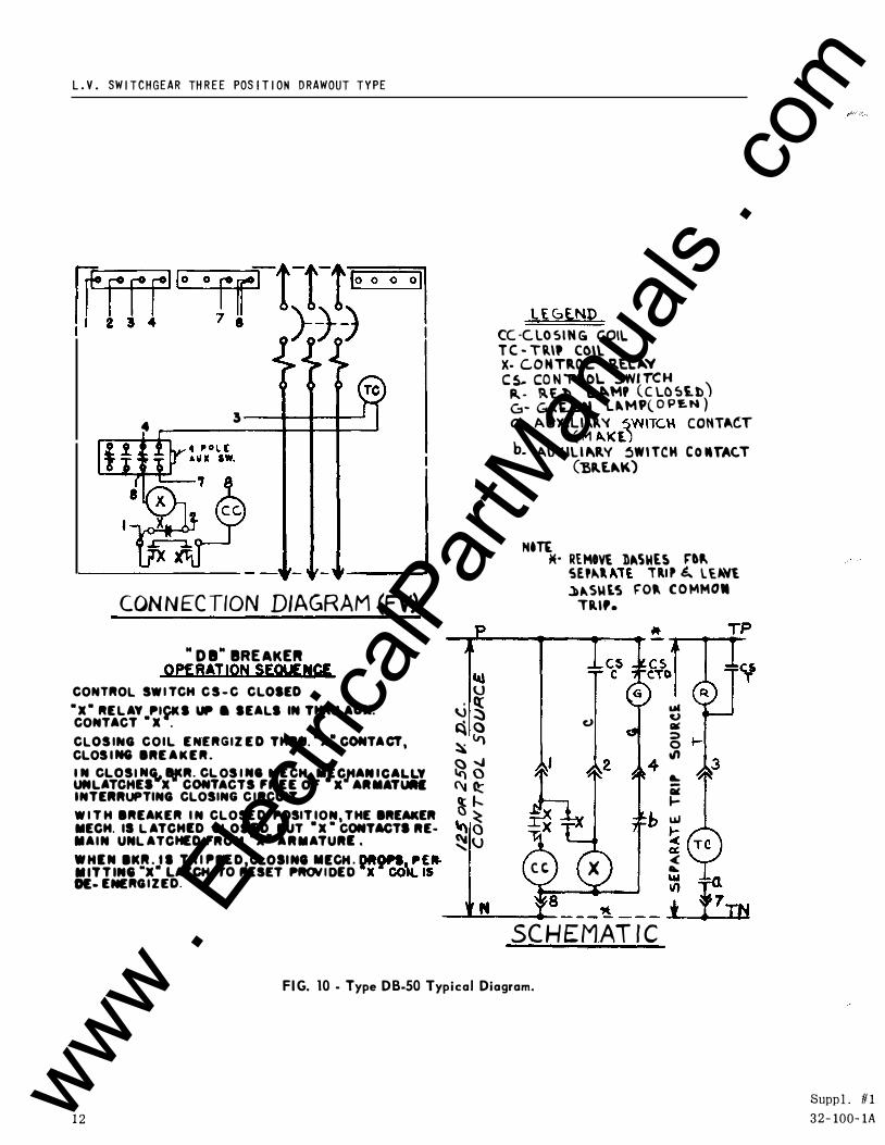
CON N EC TION DIAGRAM (FV) " D l" IRE AKEft
OPERATION SEQUENCI IU
L E GE.ND CCC. LO SIN G COIL T C - Tll\t CO\\. X· C..O MTilO\.. �E.L�'I C S.- CO N T ilOL � WI T'C H
ra,. . �E.b L �MP (C LO Si.b) G - Gll'-LM L"M'( 0 PEN ) a - AUXILI"P.'C �WITC\o\ CONTAC:T ( M "Kl.) b. A.U J.IU �RV !lWI TCH C o ln"AC.T
(Y,Il£.�K)
NtT£ *" REMtV£ ])._SME� J:"&� SEP�I. ... l£ T RI P &. lUNt ��SU t� fOP. C O MMO.
Til"·
CONTROL SW I TCH C S - C CLOSED U •x• RE L AY �lpK S tMt a SEALS IN THRU AUX. \.) � � CONTACT • x . � <;) c.> 111C CLOS ING C O I L E NERGIZ E D THitU. •x• CONTA CT, � V) 5 CLOS I NG BRE A K E R . t/t
::.�lT'b��"s�xBJC��\����·,::��,MJ;Jtt:�i�� � � � INTERRUPTING CLOSING C IRCUIT. � f.... I-W I T H BREAKER I N CLOSE D �OSIT ION, T HE BREAKER t... ()� uJ MECH. IS L ATCHED CLOSJ. D BUT •x • CONTACTS RE- .. , t; MAIN UNL ATCHED FROM x• A R M ATURE . � U � :rr'T�:.
K!'x-' �A����D .. �:��::c:��"o ��,rfs"" c c x � 0!- ENERG I Z ED.
_ ........ ____ _.,_a---'.!. ---� SC H E MAT I C
FI G. 10 - Type D B-50 Typical Diagram.
1 2
Supp l . # I 3 2 - 100- 1A www .
Elec
tricalP
artM
anua
ls . c
om
w rn � c 1 '0 >-' '0 0 ...... 0 I ...... """' > ......
...... w
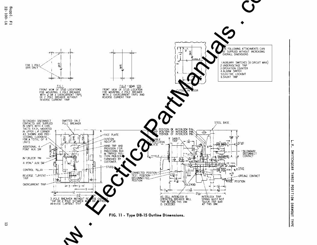
FOR 3 POLE BKR. ONLY
F I G. I
F RONT VIEW OF STUD LOCATIONS FOR MOUNTING 3 POLE BREAKER WITH 2 OR 3 OVERCURRENT TRIPS, OR 2 POLE BREAKER WITHOUT REVERSE CURRENT TRIP
SECONDARY DISCONNECT CONTACTS ARE SUPPLIED IN UNITS WITH 4 CONTACTS EACH
1 MOUNTED
IN UPPER L. H. CORNER AS SHOWN AND PRO CEEDING CLOCKW ISE FOR A TOTAL OF 4 UNITS ADDITIONAL 4 POINT AUX. SW
CONTROL RELAY---t-IN
REVERSE CURRENT T RIP
OVERCURRENT TRIP
OMITTED ON 2 POLE BREAKER
a:'
�j,
F IG. 2 - NEMA STD.
FRONT VIEW OF STUD LOCATION FOR MOUNTING 2 POLE BREAKER WITH 2 OVERCURRENT TRIPS AND REVERSE CURRENT TRIP
�' I ' I\J..R . 4 "' "' "' �HANDLE -loJ �
Lt_��
� CUTOUTJNDOOR
THE FOL LOWING ATTACHMENTS CAN BE SUPPLIED WITHOUT INCREASING OVERALL DIMENSIONS
I. AUXILIARY SWITCHES (8 CIRCUIT MAX) 2 . UNDERVOL TAGE TRIP 3 OPERATION COUNTER 4. ALARM SWITCH S.ELEHRIC LOCKOUT 6.SHUNT TRIP
STEEL BASE
FACE PLATE
MIN. POSITION OF INTERLOCK PIN.· TRIP POSITION OF INTERLOCK PIN. MAX POSITION OF INTERLOCK PIN��K-
'\: 'Y ;il
HAND TRIP AND PROVISION F O R PADLOCKING BKR IN TRIPPED POSITION. PADLOCK FURNISHED BY CUSTOMER.
STUDS
CONNECTED POSITION TEST POSITION DISCONNECTEQ POSITION
1f SHUNT ' ' TRIP
� SECONDARY DISCONNECT CONTACT
t+-----+----2112--+-------+i AS CELL INTERLOCK IS OPERATED. BREAKER WILL TRIP BEFORE THIS DIM. IS EXCEEDED.
F I G. 1 1 · Type D B- 1 5 Outl ine D i mensions.
INTERLOCK TRIP SPRING MUST NOT l�U¥�1S
T�lM _BAR
r
<
CJ) :e:
-I C") :X: � m ]> :::0
-I :X: :::0 m m
.., 0 CJ)
-I
0 :z
0 :::0 ]> :e: 0 c: -I
-I -< .., m
www . El
ectric
alPar
tMan
uals
. com
..... .;:..
w Ul N C: 1 '0 ..... '0 0 ,_. 0 I ,.... "f.k ;t. .....
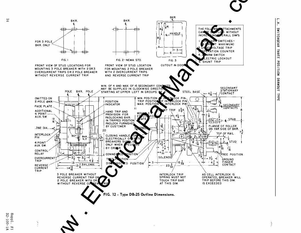
FO R 3 P O L E B K R . O N LY
-
F I G . I
B K R . It
FRONT V I EW OF ST U D LOC ATI O N S F O R M O U N T I N G 3 P O L E B R E A K E R W I T H 2 0 R 3 O V E R CU R R E NT T R I P S O R 2 P O L E B R EA KE R W I T H O U T R E V E R S E C U R R E N T T R I P.
B K R . t
$ I $
r+--, r-h t-' '--t-'
FIG. 2 - N E M A STD.
FRONT V I EW OF STUD LOCAT I O N F O R M O U N T I N G 2 P O L E B R E A K E R W I T H 2 OV E R C U R R E N T T R I P S A N D R E V E R S E C U R R E N T T R I P
B�R.
F IG . 3
C U TO U T IN D O OR
M I N . OF 4 AND MAX. O F 16 SECON DAR Y CO NTACTS MAY BE SU P P L I E D I N CLOCK W IS E D IR ECTIO N STA R T I N G AT U P PE R L E FT IN G R O U P S O F 4
M I N . POS I T I O N OF I N T E R LOCK P I N T R I P P O S I T ION O F I N T E R LO C K P I N
T H E FOLLOWING ATTAC H M E NTS C A N BE SU P P LI E D W I THOUT I N C R E A S I N G OV E R ALL D IM'S.
I. A U X I LI A RY SWITC H ES -( 8 C I R CU I T M A X I M U M)
2 . U N D E R V O LTAGE T R I P 3 . O P E R AT I O N C O U N T E R 4 . A L A R M SW ITCH 5. E L EC T R I C LO C K O U T 6 S H U N T T R I P
POSITION I N DICATOR M A X . POSI T I O N O F I N T E R LO C K P I� I\\ •�
1
4 POINT A UX . SW.
CO N T R O L R E L AY
OVERCURRENT T R I P
R E V E R S E C U R R E N T T R I P
HAND TRIP AND PROV I SION F O R PA D LOC K I N G B K R.
I I
IN TRIPPED POSITION. PA D LOCK FURNIS H ED BY C U S TO M E R
C LOS I N G HANDLE FOR =..rn�,ll \ ELEC T R I CALLY O P E RATED
3 POLE B R E A K E R WITHOUT R E V E R S E C U R R E N T T R I P OR
B R E A K E RS S U PP L I E D ONLY W H E N S P E C I F I E D B Y O R D E R
CO N N ECTED POSIT ION
TEST POSITION
2 PO L E B R E A K E R W ITH OR W I T H O U T R EV E R S E CU R R E N T T R I P
3 --2 3 32
I N T E R LO C K T R I P S P R I N G M U ST NOT TOUCH T R I P B A R AT T H I S D I M .
FI G. 12 - Type D B-25 Outl ine D i mensions.
v
GROU N D F I N G E R CO N TACT
AS C E LL I N T E R LOCK I S O P E RAT ED, B R EA K E R W I LL T R I P B E F O R E T H I S DIM. IS E X C E E D E D
r
<
(I) :e:
-t (") :::1: C) F'T1 > ::0
-t :::1: ::0 F'T1 F'T1
-o 0 (I)
-t
0 :z
0 ::0 > :e: 0 c: -t
-t -< -o F'T1
www . El
ectric
alPar
tMan
uals
. com
W C/1 � c: 1 '0 1-' '0 0 >--' 0 ,..... * ;to ,.....
,..... CJ1
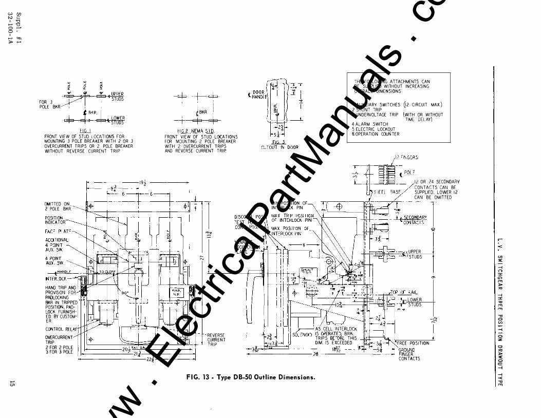
� � � li' ii' 1( 7 t lUPPER FOR 3
- STUDS POLE BKR I I I � J BKR�
LOWER 3 t STUDS llii__l
FRONT VIEW OF STUD LOCAT I ONS FOR MOUNTING 3 POLE BREAKER WITH 2 OR 3 OVERCURRENT TRIPS OR 2 POLE BREAKER WITHOUT REVERSE CURRENT T R I P
OMI1TED ON 2 POLE BKR. POSITION INDICATOR
HAND TRIP AND PROVISION FOR PADLOCKING BKR IN TRIPPED POSITION. PADLOCK FURNISHED BY CUSTOME R CONTROL RELAY· OVERCURRENT TRIP •
1 9 �
c::b i c:P �BKR i c::p .=fo
FIG. 2 NEMA STD FRONT VIEW OF STUD LOCATIONS tOR MOUNTING 2 POLE BREAKER WITH 2 OVERCURRENT ! RI PS AND REVERSE CURRENT TRIP.
r"'
"''" c<>
2 FOR 2 POLE 3 FOR 3 POLE �------------20� RAIL;, _AU __ �_'--------------�
,.._ _______
2_:14:.._22i :I
REVERSE CURRENT T R I P
M I N POSIT ION OF INTE RLOCK PIN
THE FOLLOWING ATTACHMENTS CAN BE SUPPLIED WITHOUT INCREASING OVERALL DIMENSIONS:
I. AUXILIARY SWITCHES 2 SHUNT lRIP 3 UNDERVOLTAGE TRIP
4 ALARM SWITCH S ELECTRIC LOCKOUT 6 OPERATION COUN TER
Q2 CIRCUIT MAX.)
(WITH OR WITHOUT TIME DELAY)
- �
AS CELL INTERLOCK IS OPERATE� BRK. TRIPS BEFOKE THIS DIM. I S E XCEEDED
12 OR 24 SECONDARY CONTACTS CAN BE SUPPLIED. LOWER 1 2 CAN BE OM11TED
UPPER STUDS
LOWER STUDS
Q
0>
-I"' r-"'
_k ., llfn, 181, r �--------- 28 ---------�
FREE PO S I T ION GROUND FINGER CON TACTS
F I G. 1 3 . Type D B-50 Out l ine D i men s i on s.
'
<
U) ::e:
-l ("') :::1: G> ,.., l> "" -l :::1: "" ,.., ,.., " 0 U)
-l
0 ::z
0 "" l> ::e: 0 c:: -l
-l -< " ,..,
www . El
ectric
alPar
tMan
uals
. com
...... en
W UJ tv c:
I '0 ...... '0 0 1-' 0
I ...... """ > ......
.f!' OF BREAK E R I : � : ' FOR 3 POLE BKE A K E R
O N LY � = \b =
= � �� F I G . I
F R O N T V I E W OF ST U D ARRAN G E M E NT FOR 3 PO L E BREAKE R W I TH 2 OR 3 O V E RC U R R E N T T RI PS OR 2 POLE B R E A K E R W I T HOUT R E V E R S E C U RR E N; T R I P
MOVABLE ESCUTC H E O N �
PO S I T IOIJ I N D I CATOR
ADD IT tONAL 4 POLE AUXI L I ARY SWITCH
'-
4 POLE AUX I L IARY U., 1 � ::::;r_:_r., SWITCH
FAC E PLATE
O V E R C U R R E N T - -TR I P
CONTRGL RELAY ---
1--
7�
-�ti:· ! I • I cb
�t--�- 9
F I G . 2
F R ON T V I E W O F S T U D ARRMI G E M E N T F O R 2 POLE BREAK E R W I T H 2 O V E R C I I R R E N T TR I P S A N D REV E R S E CU R R E N T
7 � g:
I l-- 2�_!oF BREAKER
r +-bi__ u]1<.9 tv) �P OF PLATFO R M
F I G . 3
C UTO OT I N DOOR � - - ,--IN - - n')
ALUM I N U M _ _ L BASE
L I F TING � BRAC K E T ---------------�
�C�I2 F I NG E R
RY CONTACTS I
! 1!:'1� -�_j__
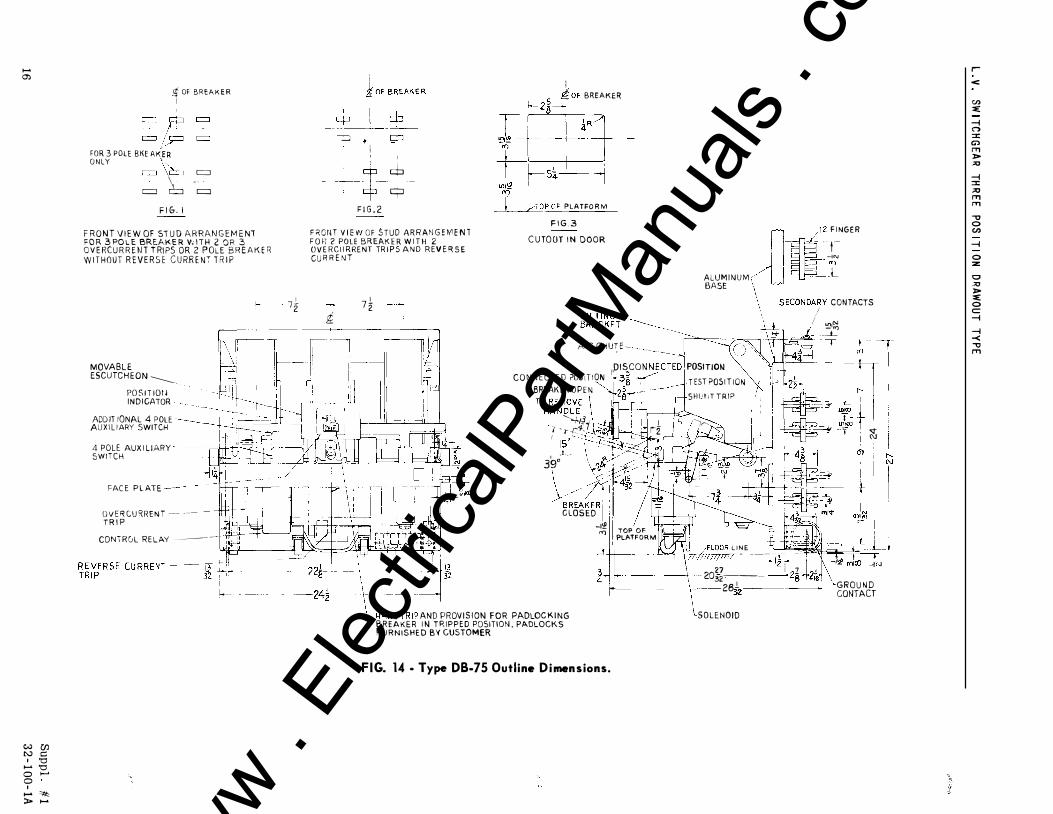
ARC CHUT E � - - --� �ISCON N�;�� POSITION I ' 5=+- j CO N N E C T E D ?OS tT. ION l-- 3s _ � - T EST POS I T I O N BREAKER OPEN �2gt -S H U t 1 T TRIP
- �� T-�h-1 TO RE MOVE��
HAN D L E , . '-..J.t}i I I l I '-, ! -,,.... I · -r -r"'�-- 'iit., ' i2 I 15'·-\-. -��
I /---- �_U � --�-� 39 �l>r l ·· - _f.:--- - � ��- ft�4tr� BREAKER ! I I / 1 � 11 C LOSED , 1t±::1J -I'£ I TOP OF
"l PLATFORM ' I -���- · � 4LOOR L INE
;//( !/1/!111 - ---27
...:-1n .. - ,
r--
�
---24� \_ "'"D TR" "D PRO" >S ' ON F O R PADCOO K ' " BR EAKER I N T R I P P E D POSITION . PADLOCKS F U R N I S H E D BY CUSTOMER
- - 2eJ. -----r--2s +z�
32 --------1 r ----1· --- 2032-. �-
2 1 7 1 GROU N D CONTACT
SOLENOID
FIG. 14 · Type DB-75 Outline D i mensions.
r
<
CJ) ::e:
-I C'"> :::t: en ..,., )> -"' -I :::t: "" ..,., ..,., ., 0 CJ)
-I
0 :z:
0 ·"' )> ::e: 0 c -I
-I -< .., ..,.,
www . El
ectric
alPar
tMan
uals
. com
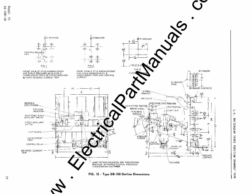
w Ul tv c: 1 '0 ...... '0 0 ...... 0 ' ...... """ ;J> ......
...... -1
j;ER
'"" ' " --$ O N LY
O L E BKE1A K E R I -It-�-F I G . I
F RO N T V I E W OF ST U D ARRANGEM ENT FOR 3 POLE BREAKER WITH 2 OR 3 O V ERCU R R E N T TRIPS OR 2 POLE B R E A K E R W I THOUT R EVERSE CURRENT T R I P
---t'"""
t ' I *-+ H'-
F I G . 2
F RONT V I E W O F STU D ARRAN G E MENT FOR 2 POL E B R EAK E R W I T H 2 O V E R C U R R ENT T R I P S A N D REV E R S E C U R R E N T
r------- 9 " 9 �
I •
•
r-z�JOF BREAKER
r �-
+-�5�-� U}j!:2 "? �p OF PLAT FOR tv\
F I G . 3 C UTO OT IN DOOR
L I F T ING ::-----..._ BRACKET ---.....__ __ -.....__
Jln� ;�NG E RS
-IN ... ALUM I NUM I BASE
NDARY CONTACTS SECO . I I
ARC C H U T E -- --------- -
MOVABLE ESCUTCHEON -...___ __ _
P O S I T I O N INDI CATOR
ADDI T I O NAL 4 POLE AUX IL IARY SWITCH
4 POLE AUX I L IARY �w �-'-SWITCH · � -,
FAC E PLATE � 11 1 1 ,, I � __L
OVE RCU RRENT -----TR I P
CONT RGL RELAY �--
R E VE R S E C U R R E NT 13+11 1�
TR I P 32 r------------- 29------�--------__J
HAND TRIP AND PROV I S I O N FOR PADLO C K I N G BREAKER IN TRIPPE D POSIT ION , PADLOCKS FURN ISHED BY CUSTOMER
F I G . 15 - Type DB-100 Out l i ne Dimensions.
GRO UN D CONTACT
SOLENOID
r
<
U) ::e: -
1'- I --i n
(\J :::t: C') I'T1 l> "" --i :::t: "" I'T1 I'T1
"'0 0 U) ---i I -0 :z 0 "" l> ::e: 0 c::: --i
--i -< "'0 I'T1
www . El
ectric
alPar
tMan
uals
. com

www . El
ectric
alPar
tMan
uals
. com

www . El
ectric
alPar
tMan
uals
. com

www . El
ectric
alPar
tMan
uals
. com
' • t i
I l .
1 1 { j
J ;J
l
-�·
I.B. 32-100-lA
DESCRIPTION • INSTALLATION • MAINTENANCE
INSTRUCTIONS
Low-V olta g e
METAL-ENCLOSED
SWITCHGEAR
.,
...
WESTINGHOUSE ELECTRIC CORPORATION SWITCHGEAR D I VI S I O N
EAST P I TTSBURGH PLANT • EAST PITTSBURGH, PA •
SUPERSEDES 1.8. 32-100-1 DECEM BER, 1 952 Printed in U.S.A. www .
Elec
tricalP
artM
anua
ls . c
om
2
TABLE OF CONTENTS
Part One DESCRIPTION Pages 7-18
Switchgear Having Types DB-15, DB-25 and DB-50 Circuit Breakers . . . . . . . . . . . . 7
Stationary Structure. . . . . . . . . . . . . . . . . . . . . . . . . . . . . . . . . . . . . . . . . . . . . . . . . . . 7
Removable Element . . . . . . . . . . . . . . . . . . . . . . . . . . . . . . . . . . . . . . . . . . . . . . . . . . . . 8
Interlocks. . . . . . . . . . . . . . . . . . . . . . . . . . . . . . . . . . . . . . . . . . . . . . . . . . . . . . . . . . . . 9
Accessories. . . . . . . . . . . . . . . . . . . . . . . . . . . . . . . . . . . . . . . . . . . . . . . . . . . . . . . . . . . 10
Inserting the Removable Element . . . . . . . . . . . . . . . . . . . . . . . . . . . . . . . . . . . . . . . l 0
Removing the Element . . . . . . . . . . . . . . . . . . . . . . . . . . . . . . . . . . . . . . . . . . . . . . . . 1 1
Switchgear Having Type DA-75 Circuit Breakers . . . . . . . . . . . . . . . . . . . . . . . . . . . . 13
Interlocks . . . . . . . . . . . . . . . . . . . . . . . . . . . . . . . . . . . . . . . . . . . . . . . . . . . . . . . . . . . . 1 3
Accessories . . . . . . . . . . . . . . . . . . . . . . . . . . . . . . . . . . . . . . . . . . . . . . . . . . . . . . . . . . . 14
Inserting the Removable Element . . . . . . . . . . . . . . . . . . . . . . . . . . . . . . . . . . . . . . . . 14
Removing the Element . . . . . . . . . . . . . . . . . . . . . . . . . . . . . . . . . . . . . . . . . . . . . . . . . 14
Switchgear Having Type DA-1 00 Circuit Breakers . . . . . . . . . . . . . . . . . . . . . . . . . . . . 17
Stationary Structure. . . . . . . . . . . . . . . . . . . . . . . . . . . . . . . . . . . . . . . . . . . . . . . . . . . 17
Removable Element . . . . . . . . . . . . . . . . . . . . . . . . . . . . . . . . . . . . . . . . . . . . . . . . . . . . 17
Inserting the Removable Element. . . . . . . . . . . . . . . . . . . . . . . . . . . . . . . . . . . . . . . . 1 7
Removing the Element. . . . . . . . . . . . . . . . . . . . . . . . . . . . . . . . . . . . . . . . . . . . . . . . . 1 8
Part Two RECEIVING, HANDLING AND STORING Page 1 9
Receiving . . . . . . . . . . . . . . . . . . . . . . . . . . . . . . . . . . . . . . . . . . . . . . . . . . . . . . . . . . . . 19
Handling . . . . . . . . . . . • . . . . . . . . . . . . . . . . . . . . . . . . . . . . . . . . . . . . . . . . . . . . . . . . . 19
Storing . . . . . . . . . . . . . . . . . . . . . . . . . . . . . . . . . . . . . . . . . . . . . . . . . . . . . . . . . . . . . . 1 9
Part Three INSTALLATION Pages 20-22
Foundation . . . . . . . . . . . . . . . . . . . . . . . . . . . . . . . . . . . . . . . . . . . . . . . . . . . . . . . . . . . 20
Placing of Stationary Structure. . . . . . . . . . . . . . . . . . . . . . . . . . . . . . . . . . . . . . . . . . 20
Power Connections . . . . . . . . . . . . . . . . . . . . . . . . . . . . . . . . . . . . . . . . . . . . . . . . . . . . 20
Ground Connection . . . . . . . . . . . . . . . . . . . . . . . . . . . . . . . . . . . . . . . . . . . . . . . . . . . . 21
Control Connection. . . . . . . . . . . . . . . . . . . . . . . . . . . . . . . . . . . . . . . . . . . . . . . . . . . . 21
Pre-operation Checks . . . . . . . . . . . . . . : . . . . . . . . . . . . . . . . . . . . . . . . . . . . . . . . . . . 22
Part Four INSPECTION AND MAINTENANCE Page 24
(
www . El
ectric
alPar
tMan
uals
. com
(
1.8. 32-100-lA L.V. METAL-ENCLOSED SWITCHGEAR
L I S T O F ILLUSTR A TIONS Figure Page
Frontispiece-Typical Installation of Indoor Metal-Enclosed Switchgear . . . . . . . . . . 4
l Front View of Indoor Metal-Enclosed Switchgear Containing Types DB-25
and DB-50 Circuit Breakers as Removable Elements . . . . . . . . . . . . . . . . . . . . . 6
2 Low-Voltage Switchgear Installed in an Outdoor Weatherproof Housing . . . . . 7
3 View of Rear Bus Compartment . . . . . . . . . . . . . . . . . . . . . . . . . . . . . . . . . . . . . . . . . 7
4 Micarta Bus Supports Arranged for One Bus Bar Per Phase . . . . . . . . . . . . . . . . 8
5 Micarta Bus Supports Arranged for Two Bus Bars Per Phase . . . . . . . . . . . . . . . . 8
6 Micarta Bus Supports Arranged for Three Bus Bars Per Phase . . . . . . . . . . . . . . 8 7 Compartment for Type DB- 1 5 Circuit Breaker . . . . . . . . . . . . . . . . . . . . . . . . . . . . 9
8 Removable Element for Type DB- 1 5 Circuit Breaker . . . . . . . . . . . . . . . . . . . . . . . 9
9 Compartment for Type DB-25 Circuit Breaker . . . . . . . . . . . . . . . . . . . . . . . . . . . . 10
1 0 Removable Element for Type DB-25 Circuit Breaker . . . . . . . . . . . . . . . . . . . . . . . 10
1 1 Compartment for Type DB-50 Circuit Breaker . . . . . . . . . . . . . . . . . . . . . . . . . . . . 1 1
1 2 Removable Element for Type DB-50 Circuit Breaker . . . . . . . . . . . . . . . . . . . . . . . 1 1
1 3 Switchgear Having Conjunction Parts for Mounting Smaller Removable
Elements . . . . . . . . . . . . . . . . . . . . . . . . . . . . . . . . . . . . . . . . . . . . . . . . . . . . . . . . . . 1 2
1 4 Placing Type DB-25 Removable Element on the Rail Extensions Using a Hoist . . . 1 2
1 5 Type DB-25 Element in Position on Rail Extensions Ready for Insertion in the
Compartment . . . . . . . . . . . . . . . . . . . . . . . . . . . . . . . . . . . . . . . . . . . . . . . . . . . . . . 1 2
1 6 Inserting a Type DB-25 Removable Element . . . . . . . . . . . . . . . . . . . . . . . . . . . . . . 1 3
17 Placing Type DB-50 Removable Element in Compartment Using the Handling
Carriage . . . . . . . . . . . . . . . . . . . . . . . . . . . . . . . . . . . . . . . . . . . . . . . . . . . . . . . . . . 1 3
1 8 Levering in a Type DA-75 Removable Element . . . . . . . . . . . . . . . . . . . . . . . . . . . 1 4
1 9 Compartment for Type DA-75, 2000-Ampere Circuit Breaker . . . . . . . . . . . . . . . 1 5
20 Removable Element for Type DA-75, 2000-Ampere Circuit Breaker . . . . . . . . . . 1 5
21 Automatic Shutters in a Type DA- 100, 4000-Ampere Compartment-Open
Position . . . . . . . . . . . . . . . . . . . . . . . . . . . . . . . . . . . . . . . . . . . . . . . . . . . . . . . . . . . 1 6
22 Automatic Shutters in a Type DA-100 Compartment-Closed Position . . . . . . . . . 1 6
23 Removable Element for Type DA-100, 4000-Ampere Circuit Breaker . . . . . . . . . 1 6
24 Compartment for Type DA-100, 5000- or 6000-Ampere Circuit Breaker . . . . . . 1 7
25 Removable Element for Type DA-100, 5000- or 6000-Ampere Circuit Breaker . . 1 7
26 Metal-Enclosed Switchgear Partially Prepared for Shipment . . . . . . . . . . . . . . . . 1 9
27 Dimensions for Locating Stationary Structure . . . . . . . . . . . . . . . . . . . . . . . . . . . . . 20
28 Cable Clamping Block Arrangements . . . . . . . . . . . . . . . . . . . . . . . . . . . . . . . . . . . 21
3 /
www . El
ectric
alPar
tMan
uals
. com
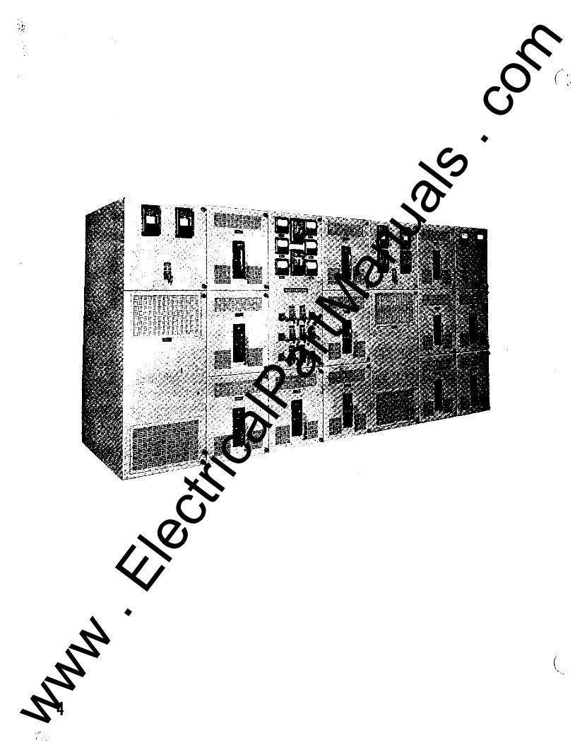
(
4 www . El
ectric
alPar
tMan
uals
. com
(
I.B. 32-100-lA L.V. METAL-ENCLOSED SWITCHGEAR
Low· Voltage
METAL-ENCLOSED SWITC HGEAR
This instruction book has been pre: pared to familiarize the purchaser's
engineering and operating staff with the low-voltage (600 volts or lower)
metal-enclosed switchgear supplied by Westinghouse. The information con
tained herein should be carefully studied before attempting to install or operate
the equipment.
Proper installation, operation and maintenance are necessary to assure
continued satisfactory servic� from the equipment. It should not be installed
in places where it will be called upon to operate at voltages or currents greater
than those for which it was designed.
For instructions pertaining to a particular piece of apparatus supplied as
part of the switchgear equipment, refer to the instruction book 01 leaflet ap.
plying to that particular type of apparatus. Copies of the applicable publica
tions are furnished along with this book for each switchgear installation .
•
Caution: Only authorized and properly trained personnel should
be permitted to operate or handle any portion of the switchgear.
5 www . El
ectric
alPar
tMan
uals
. com
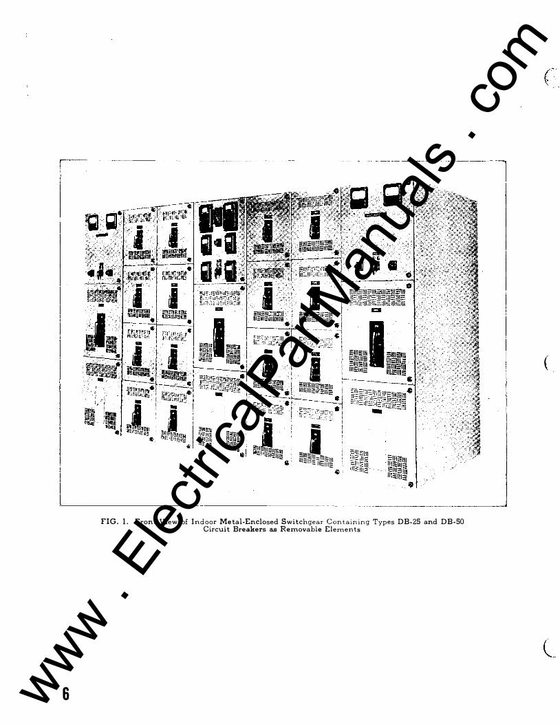
I !l!!ii :-. � �- ;g � •
FIG. 1 .
6
-
�����:::,-,,!!!:::111 ' - :::111;: �
-ll fi . Gl ' '
Front View of Indoor Metal-Enclosed Switchgear Containing Types DB-25 and DB-50 Circuit Breakers as Removable Elements
(
www . El
ectric
alPar
tMan
uals
. com
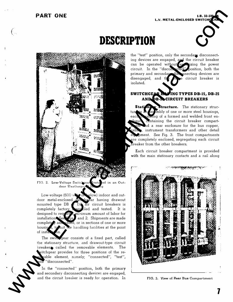
( \
(
(
PART O N E I.B. 32-100-lA L.V. METAL-ENCLOSED SWITCHGEAR
DESCRIPTION
FIG. 2. Low-Voltage Switchgear I nstalled in an Out
door Weatherproo f Housing
Low-voltage (600 volts or below) indoor and out
door metal-enclosed switchgear having drawout mounted type DB or DA air circuit breakers is
completely factory assembled and tested. It is
designed to require a minimum amount of labor for
installation. See Figs. l and 2. Shipments are made completely assembled, or in sections of one or more
housings, to suit the handling facilities at the point
of installation .
The switchgear consists of a fixed part, called
the stationary structure, and drawout-type circuit
breakers, called the removable elements. The
switchgear provides for three positions of the re
movable element, namely; "connected", "test",
and "disconnected" .
In the "connected" position, both the primary
and secondary disconnecting devices are engaged,
and the circuit breaker is ready for operation. In
the "test" position, only the secondary disconnect
ing devices are engaged, and the circuit breaker
can be operated without energizing the power
circuit . In the "disconnected" position, both the
primary and secondary disconnecting devices are
disengaged, and the entire circuit breaker is
isolated.
SWITCHGEAR HAVING TYPES DB-15, DB-25 AND DB-50 CIRCUIT BREAKERS
S tationary Structure. The stationary struc
ture is an assembly of one or more steel housings,
each consisting of a formed and welded front en
closure containing the circuit breaker compart
ments and a rear enclosure for the bus copper, cables, instrument transformers and other detail
equipment. See Fig. 3. The front compartments
are completely enclosed, segregating each circuit
breaker from the other breakers.
Each circuit breaker compartment is provided
with the main stationary contacts and a rail along
FIG. 3. View of Rear Bus Compartment
1 www . El
ectric
alPar
tMan
uals
. com
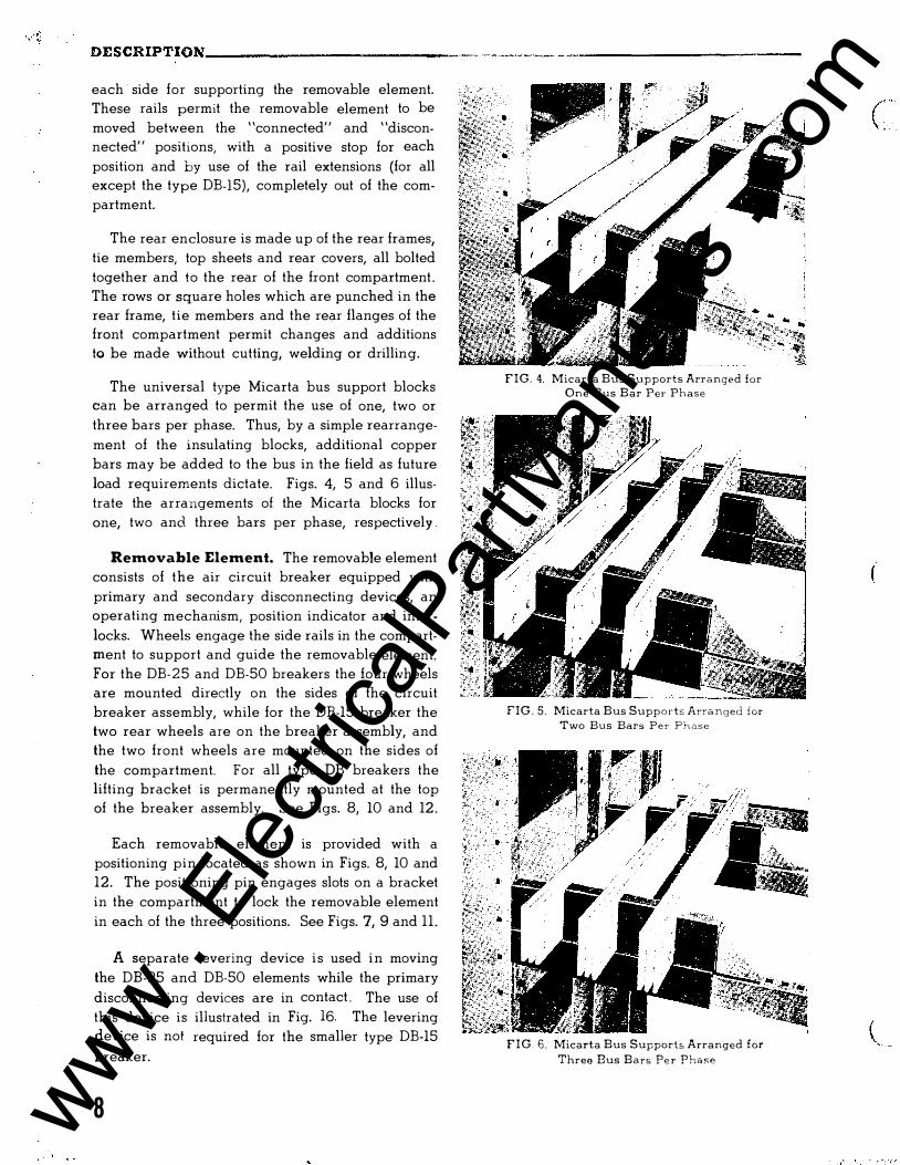
DESCRIPTION ______________ ·-·-- - ·-·-- -------- -·--·- -·-�-----------
each · side for supporting the removable element.
These rails permit the removable element to be
moved between the "connected, and "discon
nected, positions, with a positive stop for each
position and by use of the rail extensions (for all
except the type DB-15), completely out of the com
partment.
The rear enclosure is made up of the rear frames,
tie members, top sheets and rear covers, all bolted
together and to the rear of the front compartment .
The rows or square holes which are punched in the
rear frame, tie members and the rear flanges of the
front compartment permit changes and additions
to be made without cutting, welding or drilling.
The universal type Micarta bus support blocks can be arranged to permit the use of one, two or
three bars per phase. Thus, by a simple rearrange
ment of the insulating blocks, additional copper
bars may be added to the bus in the field as future
load requirements dictate. Figs. 4, 5 and 6 illus
trate the arrangements of the Micarta blocks for
one, two and three bars per phase, respectively .
Removable Element. The removable element
consists of the air circuit breaker equipped with
primary and secondary disconnecting devices, an
operating mechanism, position indicator and inter
locks. Wheels engage the side rails in the compart
ment to support and guide the removable element.
For the DB- 2 5 and DB-50 breakers the four wheels
are mounted directly on the sides of the circuit
breaker assembly, while for the DB-15 breaker the
two rear wheels are on the breaker assembly, and
the two front wheels are mounted on the sides of
the compartment. For all type DB breakers the
lifting bracket is permanently mounted at the top
of the breaker assembly. See Figs. 8, 10 and 12.
Each removable element is provided with a
positioning pin located as shown in Figs. 8, 10 and
12. The positioning pin engages slots on a bracket
in the compartment to lock the removable element
in each of the three positions. See Figs. 7, 9 and ll .
A separate levering device i s used i n moving
the DB-25 and DB-50 elements while the primary
disconnecting devices are in contact . The use of
this device is illustrated in Fig. 16. The levering
device is not required for the smaller type DB-15
breaker.
8
F I G . 4. Micarta Bus Supports Arranged for One Bus Bar Per Phase
FIG . 5 . Micarta Bus Supports Arranged ior Two Bus Bars Per Phase
F I G . 6. Micarta Bus Supports Arranged for Three Bus Bars Pe r Phase
( ' , .
(
www . El
ectric
alPar
tMan
uals
. com
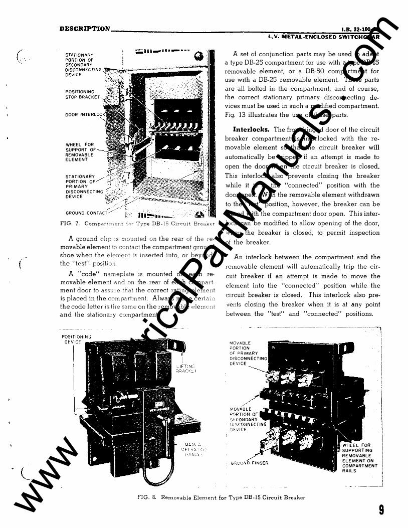
( ' . . .
(
DESCRIPTION __________________________________ ���������·�·B;-�3 2;·;100�-�; L,V. METAL-ENCLOSED SWITCHGEAR
POSITION ING
STOP BRAC K E T
DOOR
WHEEL FOR
SUPPORT OF
REMOVA B L E E L E M E N T
STAT IONARY
PORTION OF P R I M A R Y
DISCONNECTING D E V I C E
//' GROUND C O N TACT
FIG. 7. Compart ment {or Type DB - I S Circuit Breai<er
A ground clip 1 s mounted on the rear of the removable element to contact the compartment ground
shoe when the element is inserted into, or beyond,
the "test" position .
A "code" nameplate is mounted on each re
movable element and on the rear of each compart
ment door to assure that the correct rat ing element is placed in the com pa rtment . Always make certain
the code letter is the same on the removable Plemcnt
and the stationary compartment.
A set of conjunction parts may be used to adapt
a type DB-25 compartment for use with a type DB-IS
removable element, or a DB-50 compartment for
use with a DB-25 removable element. These parts
are all bolted in the compartment, and of course,
the correct stationary primary disconnecting de
vices must be used in such a modified compartment.
Fig. 13 illustrates the use of these parts.
Interlocks. The front hinged door of the circuit
breaker compartment is interlocked with the re
movable element so that the circuit breaker will
automatically be tripped if an attempt is made to
open the door when the circuit breaker is closed.
This interlock also prevents closing the breaker
while it is in the "connected" position with the
door open. With the removable element withdrawn
to the "test" position, however, the breaker can be
closed with the compartment door open. This inter
lock can be modified to allow opening of the door,
when the breaker is closed, to permit inspection
of the breaker.
An interlock between the compartment and the
removable element will automatically trip the cir
cuit breaker if an attempt is made to move the
element into the "connected" position while the
ci rcuit breaker is closed . This interlock also pre
vents closing the breaker when it is at any point
between the "test" and "connected" positions.
--�--�- --- - --- - ------ -------� MOVABLE PORTION OF P R I MARY
D I S C O N N ECTING
D E V I C E
DEV ICE
E L FOR
SUPPORTING
R E MOVABLE
E L E MENT ON COMPARTMENT R A I L S
I
I _ _ _ _j
FIG. B. Removable Element for Type DB - 1 5 Circuit Breaker
9 www . El
ectric
alPar
tMan
uals
. com
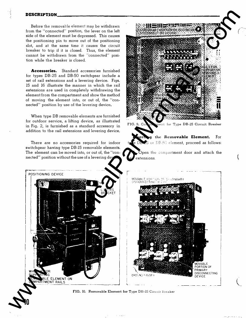
DESCRIPT,ION ______________________________________________________ __
I I I
Before the removable element may be withdrawn from the "connected" position, the lever on the left side of the element must be depressed. This causes the positioning pin to move out of the positioning slot, and at the same time it causes the circuit breaker to trip if it is closed. Thus, the element cannot be withdrawn from the "connected" position while the breaker is closed.
Accessories. Standard accessories furnished for types DB-25 and DB-50 switchgear include a set of rail extensions and a levering device. Figs. 15 and 16 illustrate the manner in which the rail extensions are used in completely withdrawing the element from the compartment and show the method of moving the element into, or out of, the "connected" position by use of the levering device.
When type DB removable elements are furnished for outdoor s ervice, a lifting device, as illustrated in Fig. 2, is furnished as a standard accessory in addition to the rail extensions and levering device.
There are no accessories required for indoor switchgear having type DB-15 removable elements. The element can be moved into, or out of, the "connected" position without the use of a levering device.
----- � � --� �
POS I T I O N I N G D E V I C E
I W H E E LS FOR
PPORT I N G
MOVABLE ELEMENT ON M PART M E N T RAILS
-�--�--- - ���---------------1
F I G . 9. Compartme,-,t for Type DB-25 Circuit Breaker
I nserting the Removable Element. For
type DB-25 or DB- 5:) element, proceed as follows:
1 . Open the" compa rtment door and attach the
rail extensions.
- �-------,
MOVABLE PORTION OF PRIMARY DISCONNECTING DEVICE
I I I I I I I
FIG. 10. Removable Element for Type DB-25 Circui i Breaker
10
( __ _
www . El
ectric
alPar
tMan
uals
. com
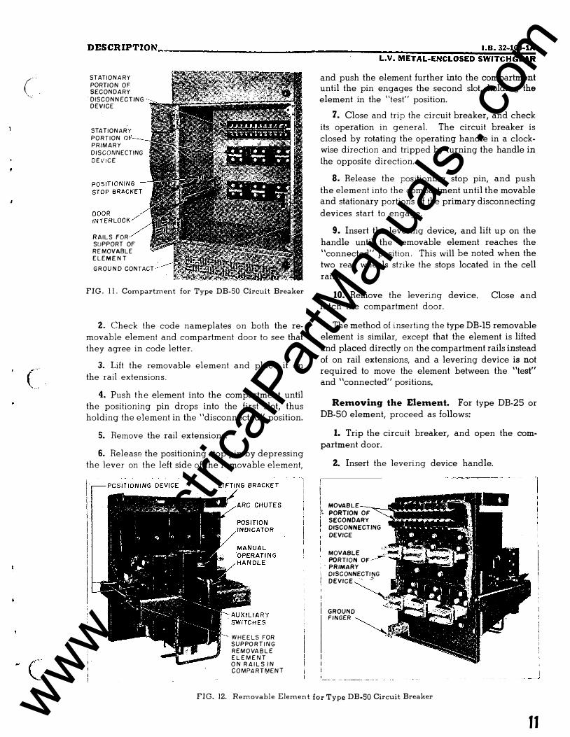
( '·:
DESCRIPTION ________________________ �--------���������· ·;8 .�3�2-�1��;�� LV. METAL-ENCLOSED SWITCHGEAR
STATION A R Y
PORTI O N O F SECONDARY
DISCONN ECTING DEVICE
STATIONARY
P O R T I O N
P R I M A R Y
D I S C O NNECTING
D E V I C E
R A I L S FOR
SUPPORT OF
R E MOVABLE
E L E M E N T
G R OU N D CONTACT
FIG . 1 1 . Compartment for Type DB-50 Circuit Breaker
2. Check the code nameplates on both the removable element and compartment door to see that they agree in code letter.
3. Lift the removable element and place it on the rail extensions .
4. Push the element into the compartment until the positioning pin drops into the first slot, thus holding the element in the "disconnected" position.
5. Remove the rail extensions.
6. Release the positioning stop pin by depressing the lever on the left side of the removable element,
W H E E LS FOR S U P PO R T I N G
R E M O VA B L E
E L E M E N T O N R A I L S I N C O M PA R T M E N T
and push the element further into the compartment until the pin engages the second slot, holding the element in the "test" position.
7. Close and trip the circuit breaker, and check its operation in general. The circuit breaker is closed by rotating the operating handle in a clockwise direction and tripped by turning the handle in the opposite direction.
8. Release the positioning stop pin, and push the element into the compartment until the movable and stationary portions of the primary disconnecting
devices start to engage.
9. Insert the levering device, and lift up on the handle until the removable element reaches the "connected" position . This will be noted when the two rear wheels strike the stops located in the cell rails.
10. Remove the levering device. Close and latch the compartment door.
The method of inserting the type DB-15 removable element is similar, except that the element is lifted and placed directly on the compartment rails instead of on rail extensions, and a levering device is not required to move the element between the "test" and "connected" positions.
Removing the Element. For type DB-25 or DB-50 element, proceed as follows:
1. Trip the circuit breaker, and open the compartment door.
i i
2. Insert the levering device handle.
! MOVABLE
:� PORTION OF
SECONDARY
DISCONNECTING
DEVICE
MOVABLE
PORTION OF
, . PRIMARY I OISCONNECTi t:IG
! DEVICE - '
GROUND FI NGER
FIG. 12. Removable Element for Type DB-50 Circuit Breaker
11 www . El
ectric
alPar
tMan
uals
. com
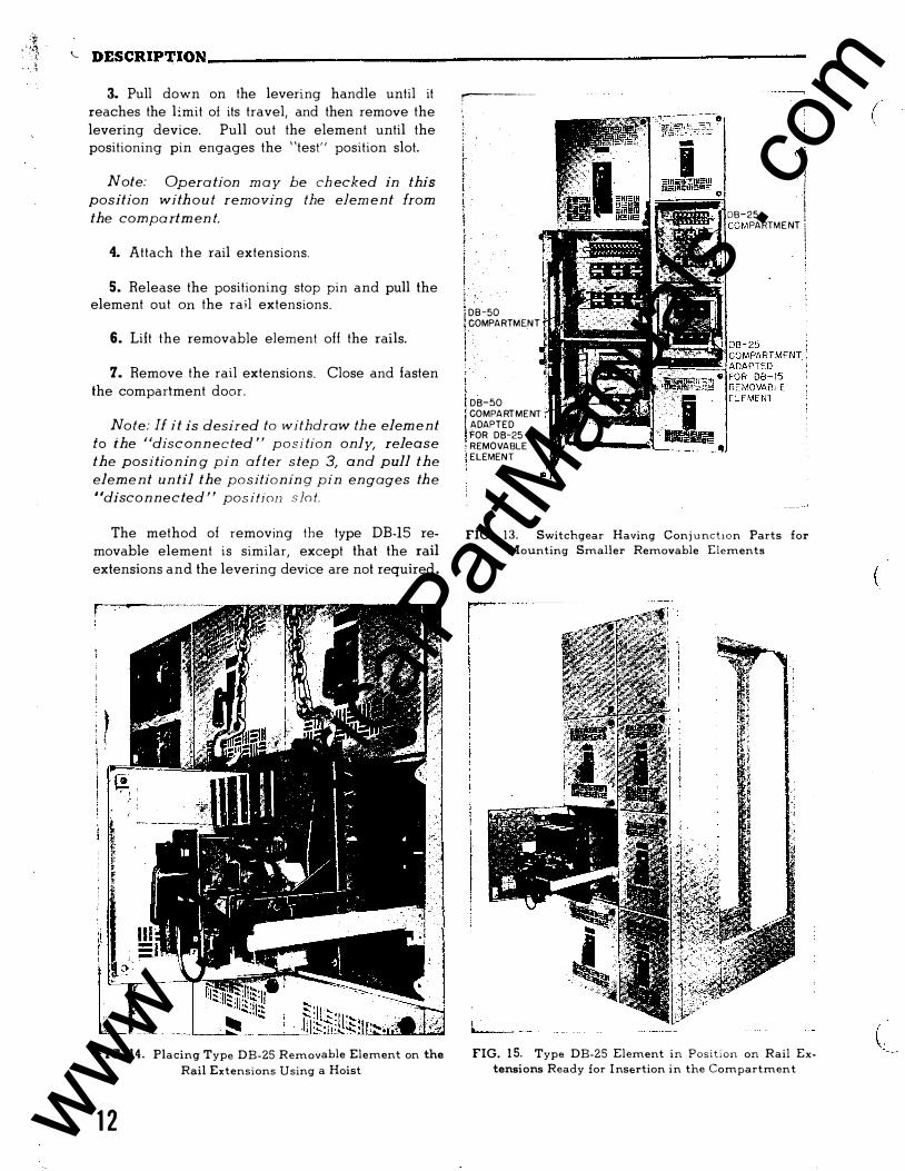
;:jr ' �>·1-, . . ·. ?,
. ' ·� � DESCRIP�ION--------------------------------------------------------
3. Pull down on the levering handle until it reaches the limit of its travel, and then remove the levering device. Pull out the element until the positioning pin engages the "test" position slot.
Note: Opera tion m a y be ch ecked in this
position with o u t removin g the elem ent from
the compa rtm en t.
4. Attach the rail extensions.
5. Release the positioning stop pin and pull the element out on the rail extensions.
6. Lift the removable element off the rails.
7. Remove the rail extensions. Close and fasten the compartment door.
Note: If it is desired to withdraw th e elem ent
to the "disc on n e c ted " position only, release
the positio n in g pin after s tep 3, and pull the
eleme n t un til the positionin g pin en gages th e
"disconnected " pos ifjon s lo t.
The method of removing the type DB-15 removable element is similar, except that the rail extensions and the levering device are not required .
FIG. 14. Placing Type DB-25 Removable Element on the Rail Extensions Using a Hoist
1 2
�----
DB-50 COMPARTMEN T
DB-50 COMPARTMENT ADAPTED FOR DB-25 REMOVABLE ELEMENT
•
( l 1
DB-25 I PARTMENT J
l !
FIG. 1 3. Switchgear Having Conj u nction Parts for Mounting Smaller Removable Elements
FIG. 15. Type DB-25 Element in Position on Rail Extensions Ready for I nsertion in the Compartment
(
(
www . El
ectric
alPar
tMan
uals
. com
(
(
S W I TCHGEAR HAV I NG TYPE DB - 7 5 , DP - 1 0 0 & DB F - 4 0 C I RCU I T BREAKERS
The type DB- 75 and DB- 100 break e rs are equ ipped with wheel s so t h at
they may be rol l ed on the f l oor. DB- 100 and DBF-40 breakers are supp l ied
on l y in a "one - h i gh " arrangement so that these b reakers a lways rol l into the hous ing at floor l eve l . DB- 75 b reakers are arranged to be at f l oor
l evel whenever pos s i bl e , but can be mounted in " two- h i gh " arrangements. A portab l e extens ion p l a t form i s prov ided with two- high DB- 75 assemb l i es
to fac i l i tate insert ing or remov ing the b reaker.
The l evering device for these break e rs i s a worm gear mechani sm
mounted in the hous ing hav i ng a l ever arm on each s i de o f the compartment
to engage ro l l ers on the breaker. The interlocking mechanism cons i st s o f
a s l i de r assembly at t h e r i ght front of the compartment which i s moved
vert i cal l y by op erat ing a " p u l l - p i n " wh i ch extends thru the compartment
door. The compartment i s shown in Fi gure " A " ( p hoto 350676 ) .
I N S ERT I NG THE REMOVABLE ELEMENT
The i n terl ock ing and l ever ing- i n me chan ism operates in the fo l l ow ing
fashion start i ng w i th the compartment door open and the l evering mecha
n i sm set at " ro l l - ou t " pos i t i on.
( a ) Al i gn b reaker f l anged whe e l s with rai l s and push break e r into
compartment .
( b ) I f break e r i s p us hed s l ow l y i nto the compartment one can feel
the fl anged whe e l s sett l e into the " d i sconnected" pos i t i on
notch with the b reaker about 3/4 of the way in. ( I f the b reak
er i s c l os ed and the i nte r l ock " pu l l - p i n " has been pul l ed the
break e r w i l l also b e stopped at th i s pos i t ion by interference
of the trip inter lock parts ) .
( c ) Push bre aker into the compartment unt i l t he l evering rol l ers
engage the l evering a rms. The break e r shou l d be " open" when
this is done . Some ro l l ing i n e rt i a is he lpful · to pass thru
the d i sconnected pos i t i on notch but the break e r should not be
s l ammed into this pos i t i on.
( d ),
Pu l l out the inter l ock " pul l -p i n " - - the breake r must be " open"
to perm i t this -- and insert the crank on t he l evering shaft.
( e ) Turn ing the c rank app roximat e l y 1� turns w i l l set the ind i c ator
at " Test" pos i t ion w i t h the l ever ing arms secure l y hol d ing the
break e r i n the test pos i t i on rai l notch . I f the c rank i s re
moved and the inte r l ock " pu l l - p i n " pushed i n the breaker may
be ope rated e i th e r e l ectric a l l y or w i t h the maintenance closing
handl e for test purposes.
( f) Turn i n g the c rank approx imat e l y 16 t urns w i l l move the break e r
i n t o the " connected" pos i t ion. When the main contacts touch
after about 8 turns of the c rank , a not ice ab l e addi t ional ef
fo rt is requi red fo r about two ful l t urns to engage the con
tacts and then some reduct ion in e ffort should be not iced for
several turns unt i l the mechan ism stop i s reached.
12A www . El
ectric
alPar
tMan
uals
. com
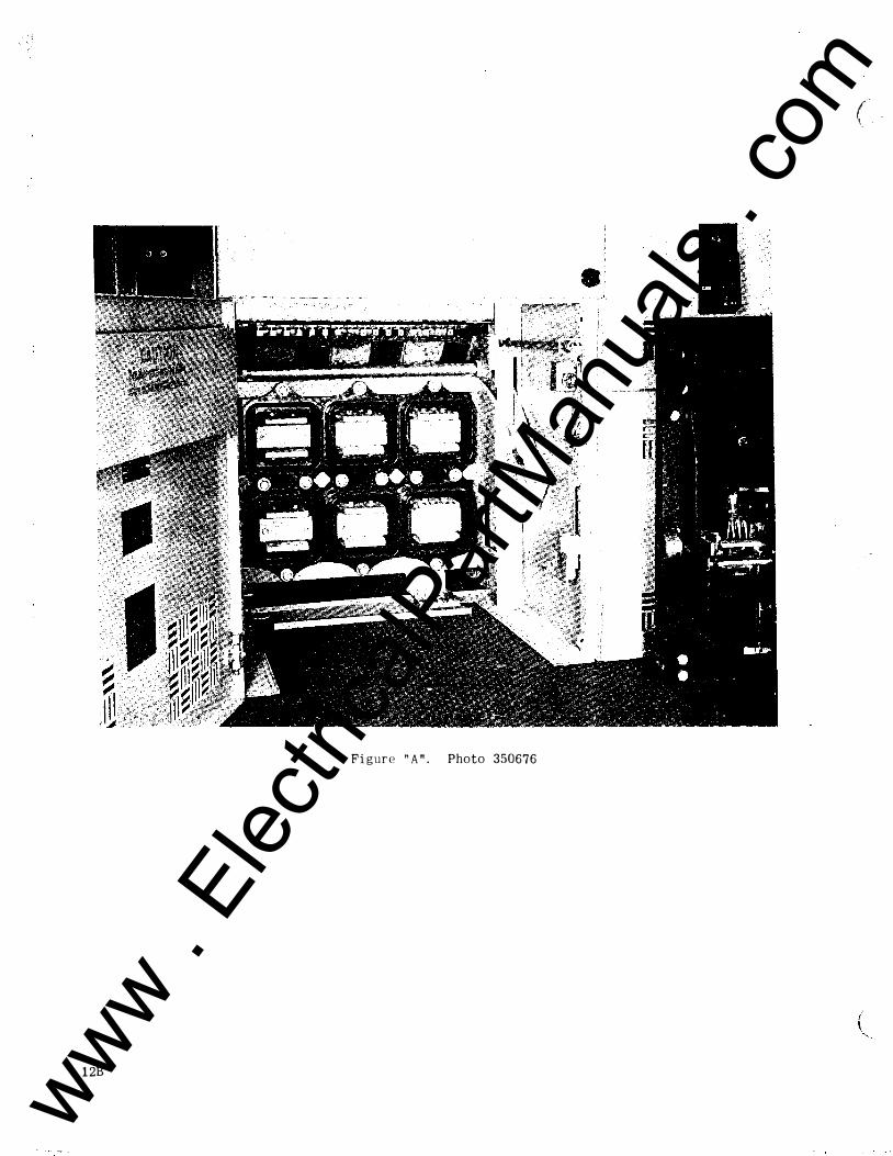
( . \, .
Fi gure " A " . Photo 350676
1 2B
www . El
ectric
alPar
tMan
uals
. com
(
,:.. 1
,, , ,
( \
\
( g ) Remove t h e crank , c l ose t h e door, secure t h e door l atch knobs, and push in the, i nterl ock " p u l l - pi n " . A door inter lock holds the breaker trip- free unt i l the door is ful ly secured. Also re l e as i ng the i n t erlock l atches the door on the inside - - i f
the interlock i s rel eased f i rst then the door cannot b e fu lly
closed.
( h ) To REMOVE the breake r the s imp l i f i ed procedure i s to:
( 1) Trip breaker.
( 2 ) Pul l interl ock " pul l -p i n " .
( 3 ) Open door.
( 4 ) Insert crank.
( 5 ) Crank breaker out to " ro l l - ou t " pos i t i on.
( 6 ) Pul l b re aker out of compartment.
The inter lock parts o f the DB- 75 are so des i gned t hat the interlock
c annot t r i p the breaker -- the breaker must be i n the open pos i t i on to
perm i t movement of the inter lock .
A l ever ing device po s i t ion i nd icator has been p l aced on the l e ft
s id e o f the compartment as shown in F igure " B " photo 350675. The test
pos i t i on is estab l ished with the l ever ing arms j ust securing the breaker
without actual l y moving i t hor i zontally -- this prevents the b re aker
" walk ing out" o f the compartment when ope rat ed e l ectrical l y . The ro l l
out and connected pos i t i ons d o not have indicat i ng marks as they are
estab l i shed by the l imit s of trave l of t he l evering device.
LUBRICATION
The l everi ng d evice should have ro l l ers and bearings lubr icated
w i th l ight mac h i ne oil and the worm gear l i ghtly coated with a med i um
fibre grease.
The main d isconnect ing finger c l usters and s tat i onary contacts
should be c l eaned periodically but KEPT DRY. Vasel i n e or grease should
NOT be app l i ed to these contact surfaces as i t w i l l ho l d d i rt and par
t i cles o f p l at i ng which w i l l c ause an increase in the l evering- i n force
required.
12C www . El
ectric
alPar
tMan
uals
. com
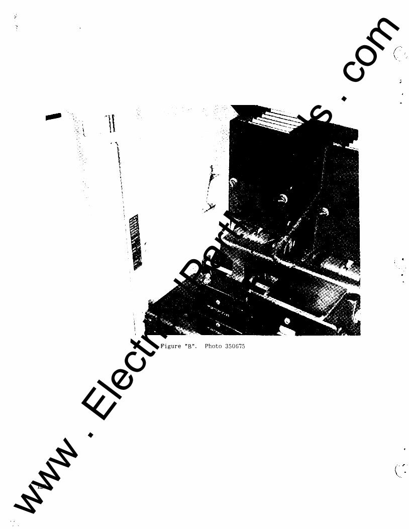
Figure " B " . Photo 3 5 0 675
120
www . El
ectric
alPar
tMan
uals
. com
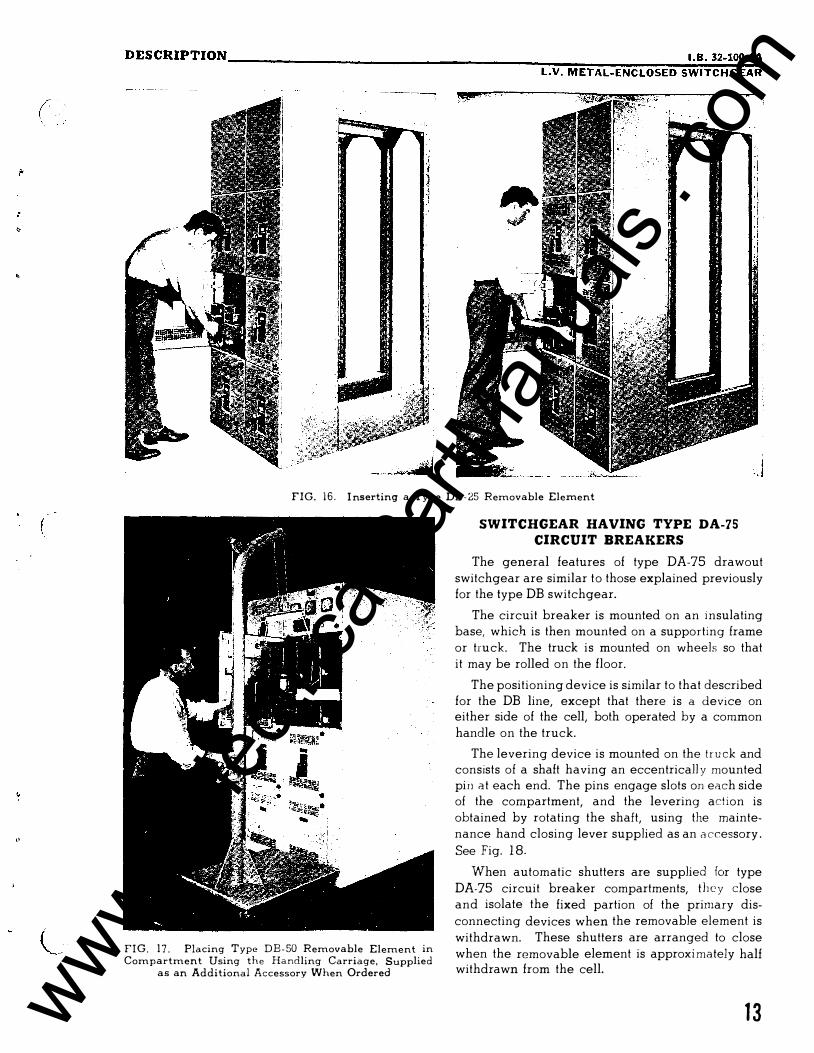
(
,.
DESCRIPTION ____________________________________ �����������. B�- �32�-�10�0�-l;A LV. METAL-ENCLOSED SWITCHGEAR
FIG. 1 6 . I nserting a Type DB- 25 Removable Element
FIG. 1 7 . Placing Type DB-50 Removable Element in Compartment Using the Handling Carriage, Supplied
as an Additional Accessory When Ordered
SWITCHGEAR HAVING TYPE DA-75 CIRCUIT BREAKERS
The general features of type DA-75 drawout switchgear are similar to those explained previously for the type DB switchgear.
The circuit breaker is mounted on an i nsulating base, which is then mounted on a supporting frame or truck. The truck is mounted on wheels so that it may be rolled on the floor.
The positioning device is similar to that described for the DB line, except that there is a device on either side of the cell, both operated by a common handle on the truck.
The levering device is mounted on the tru ck and consists of a shaft having an eccentricall y mounted pin at each end. The pins engage slots on each side of the compartment, and the levering act ion is obtained by rotating the shaft, using the maintenance hand closing lever supplied as an a ccessory .
See Fig. 1 8.
When automatic shutters are supplied for type DA-75 circuit breaker compartments, they close and isolate the fixed partion of the primary disconnecting devices when the removable element is withdrawn. These shutters are arranged to close when the removable element is approxi mately half withdrawn from the cell.
1 3 www . El
ectric
alPar
tMan
uals
. com
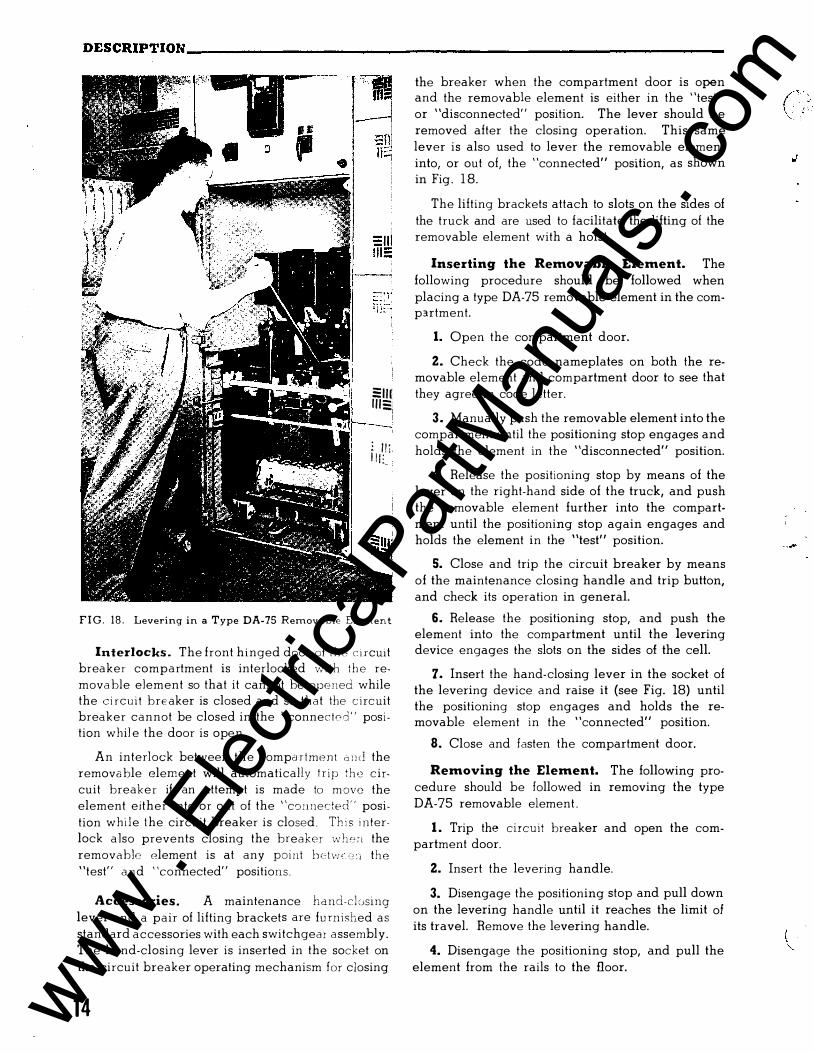
DESCRIPTION----------------------------------------------------------
Sill I l lS:: I
: I I ' in: l
FIG. 1 8 . Levering in a Type DA-75 Removable Element
Interlocks . The front hinged door of t h e c i rcuit breaker compartment is interlocked with the remova ble element so that it cannot be opened while the ci rcuit breaker is closed and so that the c ircuit breaker cannot be closed in the "connected" posi tion whil e the door is open.
An interlock between the compa rtment 2 n cl the remova ble element will automatically t r ip the c ircuit breaker if an attempt is made to m ove the element either into or out of the "co11nected" position while the circuit breaker is closed . Th i s i nterlock also prevents closing the breaker -..vhon the removable element is at any point hetv; , cc : l the "test" a n d "connected" positions .
Accessories. A maintenance hand-cl using lever and a pair of lifting brackets are fu rnished as standard accessories with each switchgear a ssembly. The hand-closing lever is inserted in the socket on
the circuit breaker operating mechanism for closing
14
the breaker when the compartment door is open and the removable element is either in the "test" or "disconnected" position. The lever should be removed after the closing operation. This same lever is also used to lever the removable element into, or out of, the "connected" position, as shown in Fig . 1 8.
The lifting brackets attach to slots on the sides of the truck and are used to facilitate the lifting of the removable element with a hoist.
Inserting the Removable Element. The following procedure should be followed when placing a type DA-75 removable element in the comp3.rtment.
1. Open the compartment door.
2. Check the code nameplates on both the removable element and compartment door to see that they agree in code letter.
3. Manually push the removable element into the compartment until the positioning stop engages and holds the element in the "disconnected" position.
4. Release the positioning stop by means of the lever on the right-hand side of the truck, and push the removable element further into the compartment until the positioning stop again engages and holds the element in the "test" position.
5. Close and trip the circuit breaker by means of the maintenance closing handle and trip button, and check its operation in general.
6. Release the positioning stop, and push the element into the compartment until the levering device engages the slots on the sides of the cell.
7. Insert the hand-closing lever in the socket of the levering device and raise it (see Fig. 18) until the positioning stop engages and holds the removable element in the "connected" position.
8. Close and fasten the compartment door.
Removing the Element. The following procedure should be followed in removing the type DA-75 removable element .
1 . Trip the circuit breaker and open the compartment door.
2. Insert the levering handle.
3. Disengage the positioning stop and pull down on the levering handle until it reaches the limit of its travel. Remove the levering handle.
4. Disengage the positioning stop, and pull the element from the rails to the floor.
( :' / ' . . '
www . El
ectric
alPar
tMan
uals
. com
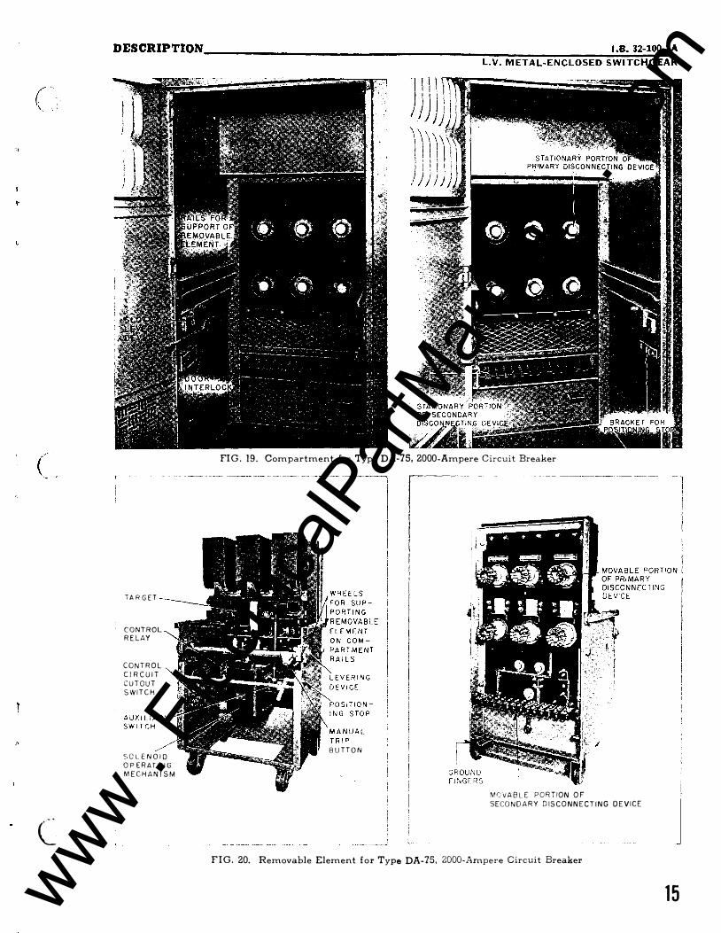
(
c
DESCRIPTION __________________________________ ���----------���.8�·�32�-�10�0-�lA LV. METAL-ENCLOSED SWITCHGEAR
T A R G E T
C O N T R O L R E LAY
C O N T R O L
C I R C U I T
C U T O U T
S W I T C H
:. G L E N O I D O P E R AT I N G
M E C H A N I S M
FIG . 19. Compartment for Type DA-75, 2000-Ampere Circuit Breaker
B U T T O N
MCVA B L E P O R TION O F
SECO N D A R Y D I S C O N N E C T I N G D E V I C E
FIG. 20. Removable Element f o r Type DA-75, 2000-Ampere Circuit Breaker
1 5 www . El
ectric
alPar
tMan
uals
. com
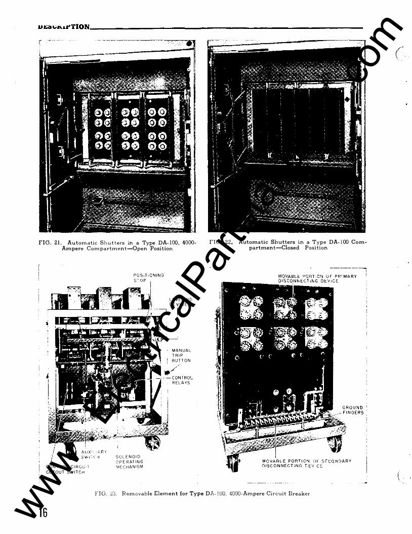
u���-&�TION--------------------------------------------------------------------
FIG. 2 1 . Automatic Shut ters in a Type DA- 1 00, 4000-Ampere Compartment-Open Position
C O N T R OL C I R G U • T CUTO U T SW I T C H
S O L. E N O I D O P E R AT I N G 'A E C HA N I S M
L E V ER I N G D E V I C E
M A N U A L T R I P B U T T O N
./ L.J'---:-- C O N T R O L
R ELAYS
FIG. 22. Automatic Shutters in a Type DA- 1 00 Compartment-Closed Position
F I G . ::::3 . Removable Element for Type DA- l OO. 4000 - Ampere Circuit Breaker
1 6
(
(
www . El
ectric
alPar
tMan
uals
. com
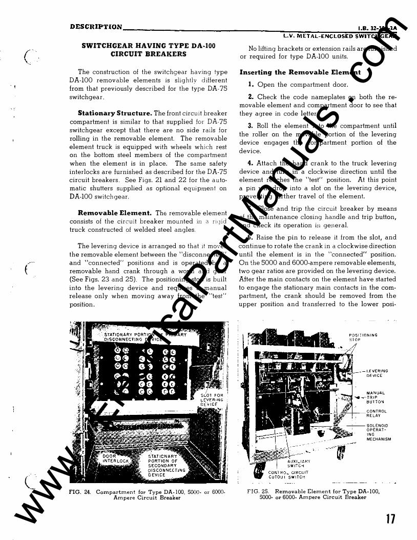
( ' '
c·
(_
DESCRIPTION ____________________________________ �����----��··�B�· �32�-�10���1A; L.V. METAL-ENCLOSED SWITCHGEAR SWITCHGEAR HAVING TYPE DA-100
CIRCUIT BREAKERS
The construction of the switchgear having type DA-100 removable elements is slight ly d ifferent from that previously described for the type DA- 75 switchgear ,
Stationary Structure. The front circu it breaker compartment is similar to that supplied for DA-75 switchgear except that there are no side rails for rolling in the removable element. The removable element truck is equipped with wheels which rest on the bottom steel members of the compartment when the element is in place. The same safety interlocks are furnished as described for the DA-75 circuit breakers . See Figs. 21 and 22 for the a utomatic shutters supplied as optional equi pmen t on DA-100 switch gear.
Removable Element. The removable element consists of the circuit breaker mounted in a riqid truck constructed of welded steel angles.
The levering device is arranged so that it moves the removable element between the "disconnected" and "connected" positions and is operated by a removable hand crank through a worm and gear (See Figs. 23 and 25). The positioning stop is built into the levering device and requires a manual release only when moving away from the "test " position.
FIG. 24. Compartment for Type DA - 1 00 , 5000- or 6000-Ampere Circuit Breaker
No lifting brackets or extension rails are furnished or required for type DA-100 units.
Inserting the Removable Element
1 . Open the compartment door.
2. Check the code nameplates on both the removable element and compartment door to see that they agree in code letter.
3. Roll the element into the compartment until the roller on the movable portion of the levering device engages the compartment portion of the device.
4. Attach the hand crank to the truck levering device and turn in a clockwise direction until the element reaches the "test" position. At this point a pin will drop into a slot on the levering device, preventing further travel of the element.
5. Close and trip the circuit breaker by means of the maintenance closing handle and trip button, and check its operation in general.
6. Raise the pin to release it from the slot, and
continue to rotate the crank in a clockwise direction until the element is in the "connected" position. On the 5000 and 6000-ampere removable elements, two gear ratios are provided on the levering device. After the main contacts on the element have started to engage the stationary main contacts in the compartment, the crank should be removed from the upper position and transferred to the lower posi-
CONTROL R E LAY
---+--- SOLENOID O P ERATI N G MECHANISM
FIG. 25. Removable Element for Type DA- 100, 5000- or 6000- Ampere Circuit Breaker
1 7 www . El
ectric
alPar
tMan
uals
. com
i ·�
DESCRIPTION ____________________________________________________ ___
tion. The crank is then rotated in a counter-clockwise direction until the element reaches the "con
nected" position. The higher gear ratio obtained with the crank in the lower position makes it easier to lever the element into the "connected" position.
7. Remove the hand crank. Close and fasten
the compartment door.
Removing the Element
1. Trip the circuit breaker and open the compartment door.
18
Z. Attach the hand crank and rotate counterclockwise until the levering device pin drops into the slot in the "test" position. (For the 5000 or 6000 ampere circuit breakers, the crank is first attached in the lower position and rotated in a clockwise direction until the main contacts are disengaged, after which the crank is transferred
to the upper position and rotated in a counterclockwise direction.)
3. Raise the stop pin and continue to rotate the
crank in a counter-clockwise direction until the
element is in the "disconnected" position.
www . El
ectric
alPar
tMan
uals
. com
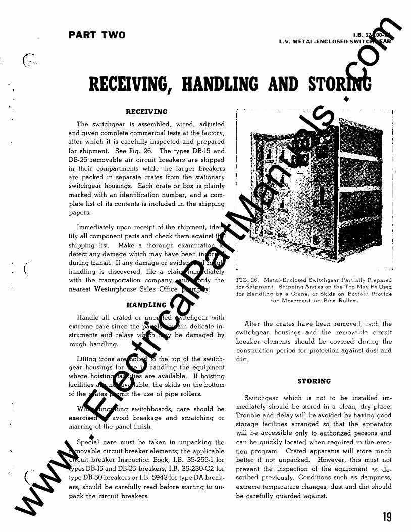
("' ' . '
(
(_
PART TWO I .B. 32-100-lA L.V. METAL-ENCLOSED SWITCHGEAR
RECEIVING, HANDLING AND STORING RECEIVING
The switchgear is assembled, wired, adjusted
and given complete commercial tests at the factory,
after which it is carefully inspected and prepared
for shipment. See Fig. 26. The types DB-15 and
DB-25 removable air circuit breakers are shipped
in their compartments while the larger breakers
are packed in separate crates from the stationary
switchgear housings. Each crate or box is plainly
marked with an identification number, and a com
plete list of its contents is included in the shipping
papers.
Immediately upon receipt of the shipment, iden
tify all component parts and check them against the
shipping list. Make a thorough examination to
detect any damage which may have been incurred
during transit. If any damage or evidence of rough
handling is discovered, file a claim immediately
with the transportation company, and notify the
nearest Westinghouse Sales Office promptly.
HANDLING
Handle all crated or uncrated switchgear with
extreme care since the panels contain delicate in
struments aild relays which may be damaged by
rough handling.
Lifting irons are bolted to the top of the switchgear housings for use in handling the equipment
where hoisting facilities are available. If hoisting
facilities are not available, the skids on the bottom
of the crates permit the use of pipe rollers.
When uncrating switchboards, care should be
exercised to avoid breakage and scratching or
marring of the panel finish.
Special care must be taken in unpacking the
removable circuit breaker elements; the applicable circuit breaker Instruction Book, LB. 35-255-l for
types DB-15 and DB-25 breakers, LB. 35-230-C2 for
type DB-50 breakers or I.B. 5943 for type DA break
ers, should be carefully read before starting to un
pack the circuit breakers.
_j
FIG . 2 6 . Metal- Enclosed Switchgear Partially Prepared
for Shipment. Shipping Angles on the Top May Be Used
for Handl ing by a Crane, or Skids on Bottom Provide
for M ovement on Pipe Rollers.
After the crates have been removed, both the
switchgear housings and the removable circuit
breaker elements should be covered d u ring the
construction period for protection against dust and
dirt.
STORING
Switchgear which is not to be installed im
mediately should be stored in a clean, dry place.
Trouble and delay will be avoided by having good
storage facilities arranged so that the apparatus
will be accessible only to authorized persons and
can be quickly located when required in the erec
tion program. Crated apparatus will store much
better if not unpacked. However, this must not
prevent the inspection of the equipment as described previously. Conditions such as dampness,
extreme temperature changes, dust and dirt should
be carefully guarded against.
1 9 www . El
ectric
alPar
tMan
uals
. com
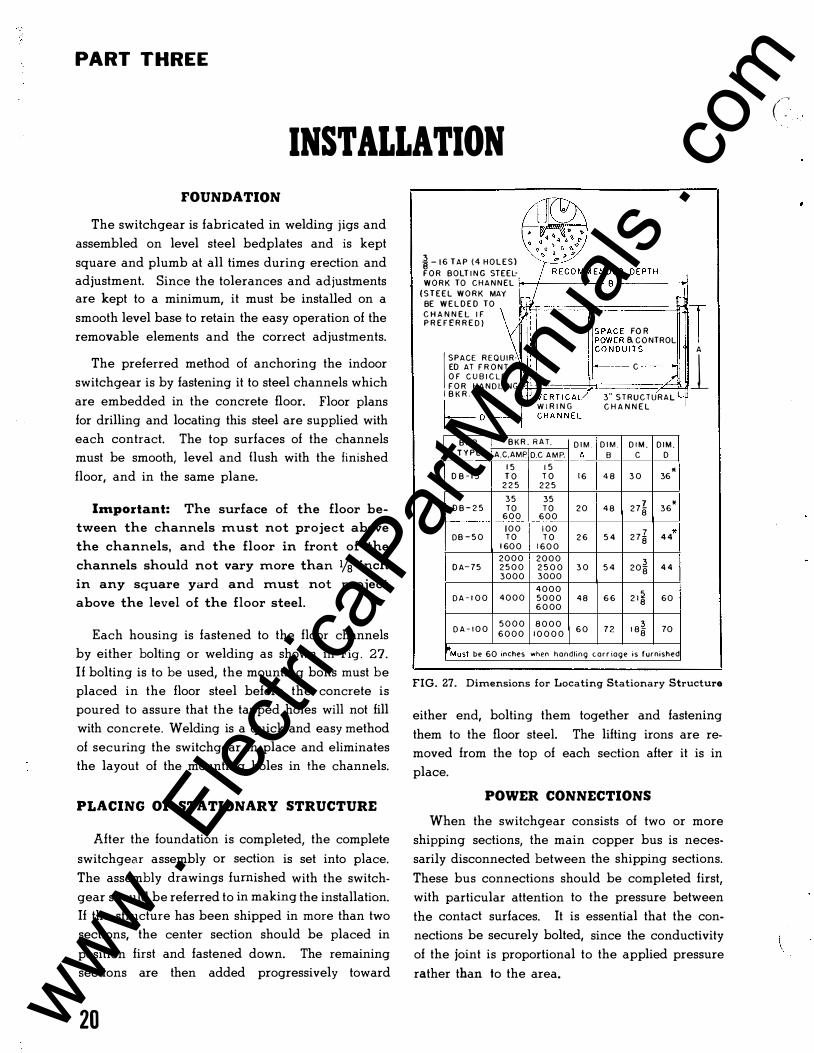
PART THREE
INSTALLATION FOUNDATION
The switchgear is fabricated in welding jigs and
assembled on level steel bedplates and is kept
square and plumb at all times during erection and
adjustment. Since the tolerances and adjustments
are kept to a minimum, it must be installed on a
smooth level base to retain the easy operation of the
removable elements and the correct adjustments.
The preferred method of anchoring the indoor
switchgear is by fastening it to steel channels which
are embedded in the concrete floor. Floor plans
for drilling and locating this steel are supplied with
each contract. The top surfaces of the channels
must be smooth, level and flush with the finished
floor, and in the same plane.
l111portant: The surface of the floor be
tween the channels must not project above
the channels, and the floor in front of the
channels should not vary more than lfa inch
in any square yard and must not project
above the level of the floor steel.
Each housing is fastened to the floor channels
by either bolting or welding as shown in Fig . 27. If bolting is to be used, the mounting bolts must be
placed in the floor steel before the concrete is
poured to assure that the tapped holes will not fill
with concrete. Welding is a quick and easy method
of securing the switchgear in place and eliminates
the layout of the mounting holes in the channels.
PLACING OF STATIONARY STRUCTURE
After the foundation is completed, the complete
switchgear assembly or section is set into place.
The assembly drawings furnished with the switch
gear should be referred to in making the installation.
If the structure has been shipped in more than two
sections, the center section should be placed in
position first and fastened down. The remaining
sections are then added progressively toward
20
i - 1 6 T A P ( 4 H O L E S ) F O R BOLT I N G STEEL· W O R K TO C H A N N E L 1---+-----
( S T E E L W O R K MAY I BE W E L D E D TO C H A N N E L I F P R E F E R R E D )
C O N D U I T S A �p6��� ;g�NTROL T
I SPACE R E Q U I R· 1 ED AT F R O N T --- C O F C U B I C L E F 0 R H A N D L I NG �·•4±====7=====:;L�lJ I B K R . V E R-TtC A7 3" S T R U C T U R A L I I W I R I N G C H A N N E L r--- D - -� C H A N N E L
B K R . B K R . R A T. D I M . D I M . D I M . T Y P E A.C.AMp D.C A M P. _fJ:_ B c
1 5 1 5 D B - 1 5 T O T O 1 6 4 8 3 0
2 2 5 2 2 5 3 5 35
2 7 I D B - 2 5 TO T O 2 0 4 8 6 0 0 6 0 0 8
1 0 0 1 00 2 7§ DB - 5 0 T O T O 2 6 5 4
1 60 0 1 6 0 0 2 0 0 0 2 0 0 0
2 0 � D A- 7 5 2 5 0 0 2 5 0 0 3 0 5 4 3000 3000 8
4 0 0 0 2 1 � D A - 1 0 0 4 0 0 0 5 0 0 0 4 8 6 6
6 0 00
D A - 1 0 0 5 0 0 0 8 0 0 0 6 0 7 2 1 8 � 6 0 0 0 1 0 0 0 0 8
D I M . D
* 36
* 36
* 4 4
4 4
60
70
�*Must be 60 inches when handling carr iage is furnished
FIG. 27. Dimensions for Locating Stationary Structure
either end, bolting them together and fastening
them to the floor steel. The lifting irons are re
moved from the top of each section after it is in
place.
POWER CONNECTIONS
When the switchgear consists of two or more
shipping sections, the main copper bus is neces
sarily disconnected between the shipping sections.
These bus connections should be completed first,
with particular attention to the pressure between
the contact surfaces. It is essential that the con
nections be securely bolted, since the conductivity
of the joint is proportional to the applied pressure
rather than to the area.
(�' www .
Elec
tricalP
artM
anua
ls . c
om
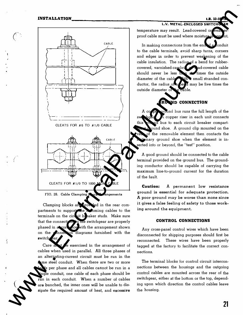
(
INSTALLATION ________________________________ ����--------���.B�-�32=-�100;-�1A L.V. METAL-ENCLOSED SWITCHGEAR
C A B L E
---.----...-1-.-..------=-== =-== = 7 I
\ 'c-=.-- --_d
CLEATS FOR ill 6 TO ill 1 /0 CABLE
CLEATS FOR ill 1 /0 TO 1 000 M CM CABLE
FIG. 28. Cable Clamping Block Arrangements
Clamping blocks are provided in the rear com
partments to support tlie incoming cables to the
terminals on the circuit breaker studs. Make sure
that the connections to the switchgear are properly
phased in accordance with the arrangement shown
on the connection diagrams furnished with the
switchgear.
Care must be exercised in the arrangement of
cables when used in parallel. All three phases of
an alternating-current circuit must be run in the
same steel conduit. When there are two or more
leads per phase and all cables cannot be run in a
single conduit, one cable of each phase should be
run in each conduit. When a number of cables
are bunched, the inner ones will be unable to dis
sipate the required amount of heat, and excessive
temperature may result. Lead-covered or weather
proof cable must be used where moisture is present.
In making connections from the end of a conduit
to the cable terminals, avoid sharp turns, corners
and edges in order to prevent weakening of the
cable insulation. The radius of a bend for rubber
covered, varnished-cambric or lead-covered cable
should never be less than six times the outside
diameter of the cable. With a small stranded con
ductor, the radius of a bend may be five times the
outside diameter of the cable.
GROUND CONNECTION
A copper ground bus runs the full length of the
switchgear. A copper riser in each unit connects
this ground bus to each circuit breaker compart
ment ground shoe. A ground clip mounted on the
rear of the removable element then contacts the
stationary ground shoe when the element is in
serted into or beyond, the "test" position.
A good ground should be connected to the cable
terminal provided on the ground bus. The ground
ing conductor should be capable of carrying the
maximum line-to-ground current for the duration
of the fault.
Caution: A permanent low resistance
ground is essential for adequate protection.
A poor ground may be worse than none since
it gives a false feeling of safety to those work
ing around the equipment.
CONTROL CONNECTIONS
Any cross-panel control wires which have been
disconnected for shipping purposes should first be
reconnected. These wires have been properly
tagged at the factory to facilitate the correct con
nections.
The terminal blocks for control circuit intercon
nections between the housings and the outgoing
control cables are mounted across the rear of the
switchgear, either at the bottom or the top, depend
ing upon which direction the control cables leave
the housing.
21 www . El
ectric
alPar
tMan
uals
. com
INSTALLATION-------------------------------------------------------
Relays designed to use movable armatures or
rotating discs have these parts tied or blocked before
shipment to protect them against possible damage
in transit. Remove all ties and blocking from the
relay armatures or discs after the switchgear is
installed and before control energy is applied.
The connections between the control wiring in
the switchgear and any remote equipment must be
of adequate size. The size of conductor required
will depend upon the distance and amount of cur
rent to be carried. When selecting wire or cable
sizes for instrument transformer circuits, the losses
in the conductor should be calculated and a check
made to assure that the combination of instrument
load and conductor losses does not exceed the
capacity of the transformer.
For electrically-operated breakers, it is important
that the voltage drop in the supply circuit be
checked to assure proper operation. This is espe
cially true where a low voltage trip source is used.
See NEMA air circuit breaker standards for the
range of control voltages at the terminals of the
operating mechanism.
The outside covering of control circuit connec
tions will depend on local conditions. If they are to
be installed in a dry place, braid-covered cable
will be satisfactory. If moisture is present, the cable
will require either a lead sheath or a weatherproof
covering.
Make sure that the polarity of the connections
from d-e control sources is correct. The polarity
is shown on the connection diagram.
When connecting external cables to the terminal
blocks on the switchgear, exercise care to assure
that the connections are properly made.
PRE-OPERATION CHECKS
After the switchgear equipment and apparatus
to be controlled have been installed and all inter
connections made, the equipment should be tested
and given a final check before being placed in
service. This is necessary to assure that the equip
ment has been correctly installed and that all con
nections are complete and have been properly
made.
22
Caution: Extreme care must b e exercised
to prevent the equipment from being con
nected to the power system while the prelimi
nary tests are being conducted . If disconnect
ing switches are not available, line leads
should be disconnected to accomplish this .
The testing equipment required will depend
entirely on the type of installation. Portable volt
meters, both a-c and d-e, with a wide range of
scales, will usually be required. If the equipment
to be put into service is quite extensive and com
plicated, both a-c and d-e ammeters should be
available in case unexpected trouble develops.
Some simple portable device for ringing or
lighting out circuits should be included in the test
ing equipment. A convenient method for the latter
is to add a solid contact point to the lens end of
a flashlight . At some other convenient place on the
flashlight add a binding post. The battery and lamp
should be connected in series between the contact
point and the binding post. One end of a flexible
wire, four or five feet in length, can be attached to
the binding post and the other end provided with
a spring clip for quick attachment to the point to be
tested. Touching the contact point at the other end
of the circuit whose continuity is being checked
should complete the circuit through the lamp.
Lighting of the lamp will indicate that the circuit
is intact .
Although the inspection and tests given the
switching equipment at the factory assure that all
the connections on the switchboard are correct
and in good order, they should be examined to make
sure that they have not been loosened or damaged
during shipment or installation . Tighten all bolted
connections and joints to assure good contact.
Ring or light out the connections to the equip
ment apart from the switchboard, such as instru
ment transformers, circuit breaker operating mecha
nisms and auxiliary switches to make sure they are
correct. The extent to which this will have to be
done depends on the thoroughness of the installa
tion work. C.
www . El
ectric
alPar
tMan
uals
. com
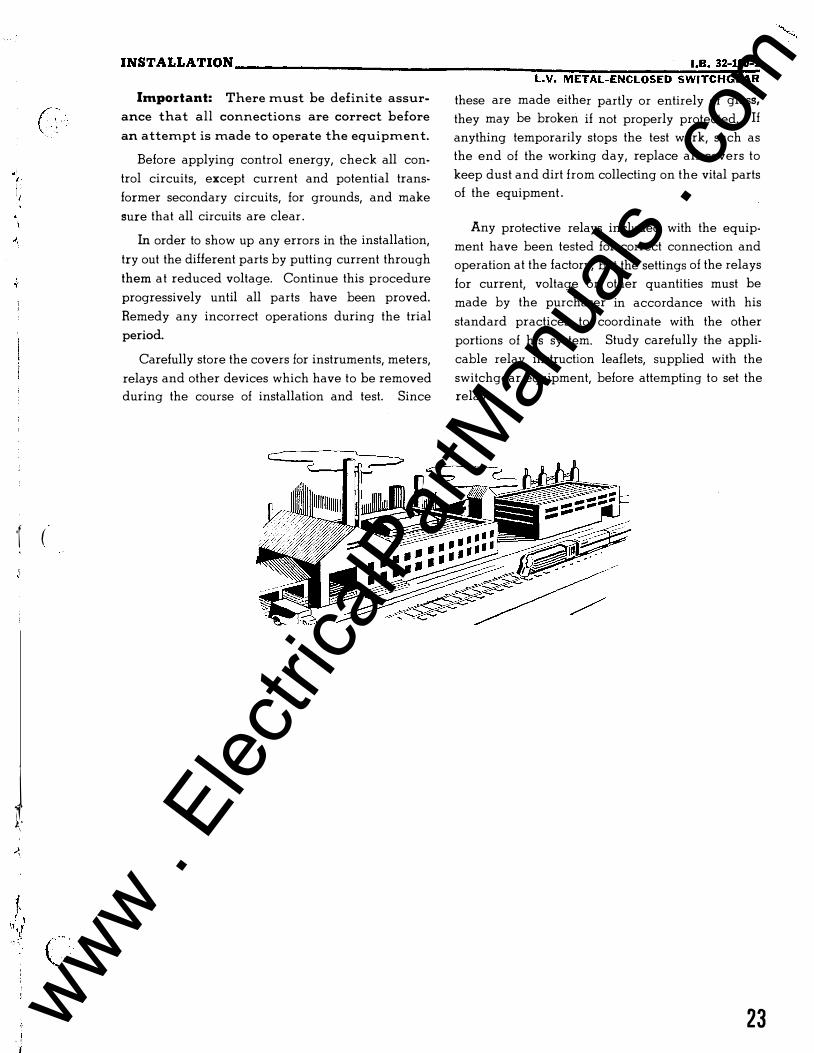
• ' ( I ' I . I
( :-'•
·r (
J I,
i . '·
r··· . . '-.· '
INSTALLATION ______________________________________ �--�--���··;8.�3�2�-1;00�-1 LV. METAL-ENCLOSED SWITCHGEAR
Important: There must be definite assur
ance that all connections are correct before
an attempt is made to operate the equipment.
Before applying control energy, check all con
trol circuits, except current and potential trans
former secondary circuits, for grounds, and make
sure that all circuits are clear .
In order to show up any errors in the installation,
try out the dilierent parts by putting current through
them at reduced voltage. Continue this procedure
progressively until all parts have been proved.
Remedy any incorrect operations during the trial
period.
Carefully store the covers for instruments, meters,
relays and other devices which have to be removed
during the course of installation and test. Since
these are made either partly or entirely of glass,
they may be broken if not properly protected. If
anything temporarily stops the test work, such as
the end of the working day, replace all covers to
keep dust and dirt from collecting on the vital parts
of the equipment .
Any protective relays included with the equip
ment have been tested for correct connection and
operation at the factory, but the settings of the relays
for current, voltage or other quantities must be
made by the purchaser in accordance with his
standard practices to coordinate with the other
portions of his system. Study carefully the appli
cable relay instruction leaflets, supplied with the
switchgear equipment, before attempting to set the
relays.
23 www . El
ectric
alPar
tMan
uals
. com
\
PART F'OUR
INSPECTION AND MAINTENANCE In order to obtain satisfactory service from the
switchgear, it must have proper inspection and
maintenance regularly.
The intervals between the inspections will be
determined by the operating and atmospheric con
ditions. Where dust is rapidly deposited within the
switchgear, especially if it is abrasive or has a high
conductivity, or where condensation occurs within
the switchgear, the inspection and cleaning should
be frequent.
The inspection must be done by experienced
personnel and should cover all the devices and
connections. Inspectors should be thoroughly in
structed and experienced in both the function and
adjustment of the various devices and should have
a uniform method of making the inspection. Good
results can very often be obtained by furnishing
the inspectors with detailed lists covering points
which need to be checked and reported at stated
intervals. Prints of all drawings and copies of all
instruction books, cards and leaflets should be
readily available in case of trouble; the mainte
nance personnel can refer to them for such detailed
information as may be required to correct the situa
tion.
Extreme care must be exercised that no circuits
are shorted or grounded and that the inspector
experiences no personal harm. Correct any defect
which is discovered, immediately.
Caution: Do not work around live parts
except in extreme emergencies. If work must
be performed on live equipment, take every
possible precaution to guard against acci
dents. Tools should be insulated, and rubber
gloves and insulating mats should be pro
vided.
Consider all connections live until the men
expecting to work on them assure themselves per-
24
sonally that the circuits are dead, and every pos
sible precaution should be taken to see that there
is no chance of a circuit being energized while
the men are working on it. Lock or block open
and place a suitable warning on switches which
have been opened to de-energize equipment for
maintenance purposes. In low-voltage metal-en
closed drawout switchgear, the removable ele
ments can be readily withdrawn to the "test" or
the "disconnected" position in which the primary
circuits are dead.
Caution: Do not touch a circuit breaker
under any circu mstances when the removable
element is in the "connected" position. Some
of the exposed parts may be live even though
the breaker is open.
Keep the premises, particularly the switchgear
room, clean. Compressed air or a hand bellows
may be used to remove dust from the interior of the
switchgear and from the removable elements. Use
an air hose equipped with an insulating nozzle to
prevent contact with live circuits, and filter the air.
Remove dirt which cannot be blown from the insu
lating surfaces with a cloth saturated with *West
inghouse Electric Corporation Solvent Material No.
1609-1, obtainable through any Westinghouse En
gineering and Service Office. (When this solvent
is not available, Stoddard Solvent or cleaner's naph
tha can be used) . Do not use abrasive material for
cleaning silverplated surfaces since the plating will
be removed, leaving the base material unprotected.
The exterior of the switchgear may be cleaned by
wiping with a chamois skin which has been im
mersed in luke warm water and wrung partially dry.
Before attempting inspection, maintenance or
adjustment of any devices such as circuit breakers,
relays, meters or instruments, read carefully the
instruction book covering the particular device.
( \
www . El
ectric
alPar
tMan
uals
. com