Embed Size (px)
Citation preview
Lubricated Compressor Pumps
Please read and save these instructions. Read carefully before attempting to assemble, install, operate or maintain the product described. Protect yourself and others by observing all safety information. Failure to comply with instructions could result in personal injury and/or property damage! Retain instructions for future reference.
Powerex • 150 Production Drive • Harrison, OH 45030 • USA1-888-769-7979 • www.powerexinc.com
IN558103AV 1/14
DescriptionGENERAL
The Powerex reciprocating air compressor has advanced compressor technology. The Powerex reciprocating compressor is available in single stage model. Individually precision machined cylinders and lap joint rings provide the lowest oil carryover in the industry.
DRY TYPE INLET FILTER
The inlet fi lter on the Powerex compressor assures 99% of particulate free air is admitted to the unit. Change every 2,500 hours or more often in dirty locations.
PISTON RINGS AND CYLINDERS
The Powerex reciprocating compressor cylinder is made of cast iron, machined with the most advanced technology available. These heat reducing cylinders eliminate the effect of excessive ring and cylinder wear.
VALVING
Low lift Swedish stainless steel valves resist carbon build-up and offer outstanding durability. The reduced number of valves lessens the risk of failure.
Safety GuidelinesThis manual contains information that is very important to know and understand. This information is provided for SAFETY and to PREVENT EQUIPMENT PROBLEMS. To help recognize this information, observe the following symbols.
Danger indicates an imminently hazardous situation which, if
not avoided, WILL result in death or serious injury.
Warning indicates a potentially hazardous situation which, if
not avoided, COULD result in death or serious injury.
Caution indicates a potentially minor or moderate injury.
Notice indicates important information, that if not
followed, may cause damage to equipment.
NOTE: Information that requires special attention.
CALIFORNIA PROPOSITION 65 This product or its power cord
may contain chemicals known to the State of California to cause cancer and birth defects or other reproductive harm. Wash hands after handling.
Breathable Air WarningThis compressor/pump is NOT equipped and should NOT be used “as is” to supply breathing quality air. For any application of air for human consumption, you must fi t the air compressor/pump with suitable in-line safety and alarm equipment. This additional equipment is necessary to properly fi lter and purify the air to meet minimal specifi cations for Grade D breathing as described in Compressed Gas Association Commodity Specifi cation G 7.1 - 1966, OSHA 29 CFR 1910. 134, ANSI and/or Canadian Standards Associations (CSA).
DISCLAIMER OF WARRANTIESIN THE EVENT THE COMPRESSOR IS USED FOR THE PURPOSE OF BREATHING AIR APPLICATION AND PROPER IN-LINE SAFETY AND ALARM EQUIPMENT IS NOT SIMULTANEOUSLY USED, EXISTING WARRANTIES ARE VOIDED, AND POWEREX DISCLAIMS ANY LIABILITY WHATSOEVER FOR ANY LOSS, PERSONAL INJURY OR DAMAGE.
2
Lubricated Compressor Pumps
4. Never use any piping smaller than the compressor connection.
5. Use fl exible hose to connect the outlet of the compressor to the piping so that the vibration of the compressor does not transfer to the piping.
SAFETY VALVES
Tank mounted compressors are shipped from the factory with safety valves installed in the tank manifold. The fl ow capacity of the safety valve is equal to or greater than the capacity of the compressor.
1. The pressure setting of the safety valve must be no higher than the maximum working pressure of the tank.
2. Safety valves should be placed ahead of any possible blockage point in the system, i.e. shutoff valve.
3. Avoid connecting the safety valve with any tubing or piping.
4. Manually operate the safety valve every six months to avoid sticking or freezing.
OperationPowerex single stage compressors operate at a maximum pressure of 145 PSIG. Compressor RPM’s are established by Powerex based on horsepower and operating pressure.
BEFORE START UP
1. Make sure all safety warnings, labels and instructions have been read and understood before continuing.
2. Remove any shipping materials, brackets, etc. 3. Confi rm that the electric power source and ground have
been fi rmly connected. 4. Be sure all pressure connections are tight. 5. Check to be certain all safety relief valves, etc., are
correctly installed. 6. Check that all fuses, circuit breakers, etc., are the proper
size. 7. Make sure the inlet fi lter is properly installed. 8. Confi rm that the tank drain valve is closed. 9. Visually check the rotation of the compressor pump. The
rotation should be counter-clockwise when facing the pulley / fl ywheel side. If the rotation is incorrect, have a qualifi ed electrician correct the motor wiring.
InstallationINSTALLATION SITE
1. The compressor must be located in a clean, well lit and well ventilated area.
2. The area should be free of excessive dust, toxic or fl ammable gases, moisture, water, and direct sunlight.
3. Never install the compressor where the ambient temperature is higher than 104° F or where humidity is high.
4. Clearance must allow for safe, effective inspection and maintenance.
5. If necessary, use metal shims or leveling pads to level the compressor. Never use wood to shim the compressor.
VENTILATION
1. If the compressor is located in a totally enclosed room, an exhaust fan with access to outside air must be installed.
2. Never restrict the cooling fan exhaust air. 3. Never locate the compressor where hot exhaust air from
other heat generating units may be pulled into the unit.
WIRING
Refer to the general product manual. All electrical hook-ups must be performed by a qualifi ed electrician. Installations must be in accordance with local and national electrical codes.Use solderless terminals to connect the electric power source.
PIPING
Refer to the general product manual.
1. Make sure the piping is lined up without being strained or twisted when assembling the piping for the compressor.
2. Appropriate expansion loops or bends should be installed at the compressor to avoid stresses caused by changes in hot and cold conditions.
3. Piping supports should be anchored separately from the compressor to reduce noise and vibration.
MINIMUM CLEARANCES
Above 24 inches
Drive belt side 12 inches
Other sides 20 inches
Model HPMax psig
SCFM @ 100 psig
RPM @ 100 psig
Number / Cylinders Bore Stroke
Flywheel Outer Diameter Drive
LPS007 0.75 145 2.1 980 1 1.97 2.56 9.45 1GR-A
LPS010A 1.0 145 3.4 1120 1 1.97 2.56 9.45 1GR-A
LPS020A 1.5 / 2 145 4.5 / 6.7 860 / 1250 1 2.56 2.56 11.2 1GR-A
LPS030A 3 145 10.1 1050 2 2.56 2.36 13.8 1GR-B
LPS050A 5 145 18.6 1150 2 2.95 2.76 14.6 1GR-B
LPS075A 7.5 145 28.0 950 2 3.54 3.35 16.9 2GR-B
LPS100A 10 145 37.0 880 2 4.13 3.35 18.3 2GR-B
NOTE: 0.5 HP and 0.75 HP pumps must be used under altitudes of 5000 feet.Above 5000 feet, 1 HP pumps must be used.
Pump Specifi cations
3
Lubricated Compressor Pumps
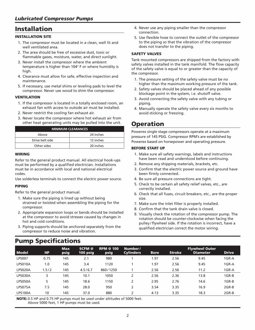
Figure 1 - Pump Dimensions
9.4 11.0
6.7 3.2
14.0
9.4 11.0
6.7 3.2
13.7
11.2 12.3
6.7 3.2
14.8
16.9 15.3
8.33.7
13.2
19.8
16.7
10.04.4
15.4
23.3 18.6
11.4
5.3
18.0
23.318.8
11.4
5.3
18.0
LPS007
LPS100A
LPS010A LPS020A
LPS030A LPS050A
LPS075A
4
AIR FILTER REPLACEMENT
1. Remove fi lter cover. 2. Install new fi lter element (P/N 91348550). 3. Reassemble fi lter cover.Do not attempt to clean and reuse fi lter cartridge.
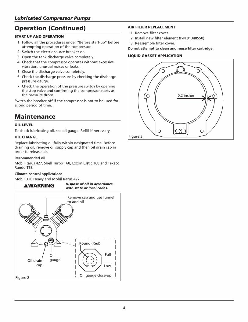
LIQUID GASKET APPLICATION
Operation (Continued)START UP AND OPERATION
1. Follow all the procedures under “Before start-up” before attempting operation of the compressor.
2. Switch the electric source breaker on. 3. Open the tank discharge valve completely. 4. Check that the compressor operates without excessive
vibration, unusual noises or leaks. 5. Close the discharge valve completely. 6. Check the discharge pressure by checking the discharge
pressure gauge. 7. Check the operation of the pressure switch by opening
the stop valve and confi rming the compressor starts as the pressure drops.
Switch the breaker off if the compressor is not to be used for a long period of time.
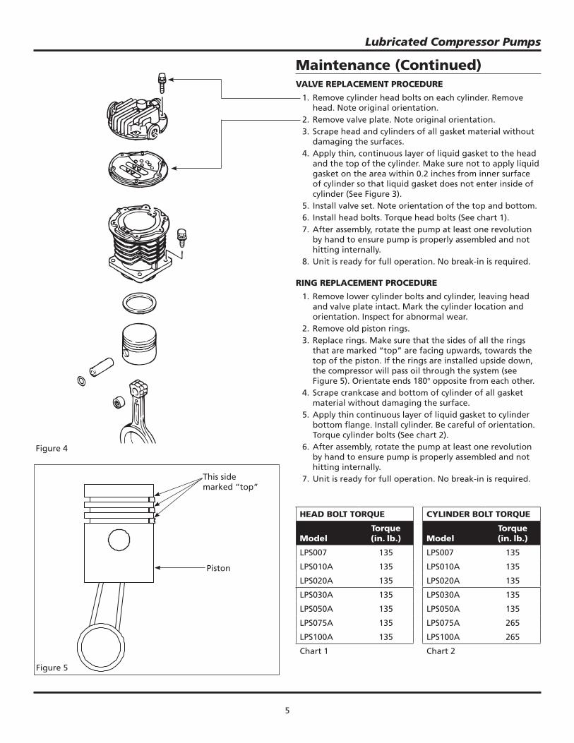
MaintenanceOIL LEVEL
To check lubricating oil, see oil gauge. Refi ll if necessary.
OIL CHANGE
Replace lubricating oil fully within designated time. Before draining oil, remove oil supply cap and then oil drain cap in order to release air.
Recommended oilMobil Rarus 427, Shell Turbo T68, Exxon Esstic T68 and Texaco Rando T68
Climate control applications Mobil DTE Heavy and Mobil Rarus 427 Dispose of oil in accordance
with state or local codes.
Figure 2
Remove cap and use funnel to add oil
Oil drain cap
Oil gauge
Oil gauge close-up
Full
Low
Round (Red)
Figure 3
0.2 inches
Lubricated Compressor Pumps
5
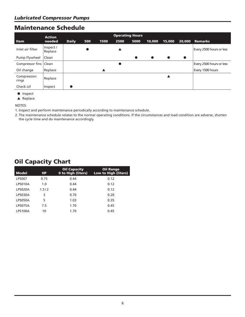
Maintenance (Continued)VALVE REPLACEMENT PROCEDURE
1. Remove cylinder head bolts on each cylinder. Remove head. Note original orientation.
2. Remove valve plate. Note original orientation. 3. Scrape head and cylinders of all gasket material without
damaging the surfaces. 4. Apply thin, continuous layer of liquid gasket to the head
and the top of the cylinder. Make sure not to apply liquid gasket on the area within 0.2 inches from inner surface of cylinder so that liquid gasket does not enter inside of cylinder (See Figure 3).
5. Install valve set. Note orientation of the top and bottom. 6. Install head bolts. Torque head bolts (See chart 1). 7. After assembly, rotate the pump at least one revolution
by hand to ensure pump is properly assembled and not hitting internally.
8. Unit is ready for full operation. No break-in is required.
RING REPLACEMENT PROCEDURE
1. Remove lower cylinder bolts and cylinder, leaving head and valve plate intact. Mark the cylinder location and orientation. Inspect for abnormal wear.
2. Remove old piston rings. 3. Replace rings. Make sure that the sides of all the rings
that are marked “top” are facing upwards, towards the top of the piston. If the rings are installed upside down, the compressor will pass oil through the system (see Figure 5). Orientate ends 180° opposite from each other.
4. Scrape crankcase and bottom of cylinder of all gasket material without damaging the surface.
5. Apply thin continuous layer of liquid gasket to cylinder bottom fl ange. Install cylinder. Be careful of orientation. Torque cylinder bolts (See chart 2).
6. After assembly, rotate the pump at least one revolution by hand to ensure pump is properly assembled and not hitting internally.
7. Unit is ready for full operation. No break-in is required.
CYLINDER BOLT TORQUE
ModelTorque (in. lb.)
LPS007 135
LPS010A 135
LPS020A 135
LPS030A 135
LPS050A 135
LPS075A 265
LPS100A 265
Chart 2
HEAD BOLT TORQUE
ModelTorque (in. lb.)
LPS007 135
LPS010A 135
LPS020A 135
LPS030A 135
LPS050A 135
LPS075A 135
LPS100A 135
Chart 1
Figure 4
Lubricated Compressor Pumps
Figure 5
This side marked “top”
Piston
6
Maintenance Schedule
ItemAction needed
Operating Hours
RemarksDaily 500 1500 2500 5000 10,000 15,000 20,000
Inlet air fi lter Inspect / Replace
● ▲ Every 2500 hours or less
Pump Flywheel Clean ● ● ● ●
Compressor fi ns Clean ● Every 2500 hours or less
Oil change Replace ▲ Every 1500 hours
Compression rings Replace
▲
Check oil Inspect ●
● Inspect ▲ Replace
NOTES:1. Inspect and perform maintenance periodically according to maintenance schedule.2. The maintenance schedule relates to the normal operating conditions. If the circumstances and load condition are adverse, shorten
the cycle time and do maintenance accordingly.
Lubricated Compressor Pumps
Model HPOil Capacity
0 to High (liters)Oil Range
Low to High (liters)
LPS007 0.75 0.44 0.12
LPS010A 1.0 0.44 0.12
LPS020A 1.5 / 2 0.44 0.12
LPS030A 3 0.70 0.20
LPS050A 5 1.03 0.35
LPS075A 7.5 1.70 0.45
LPS100A 10 1.70 0.45
Oil Capacity Chart
7
LPS075A, LPS100A
Maintenance Log
Date Maintenance Required Maintenance Performed
8
17
6
5
2
3
4
10
12
9
8
1114
13
Lubricated Compressor Pumps
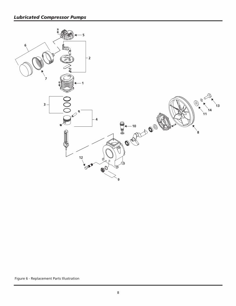
Figure 6 - Replacement Parts Illustration
9
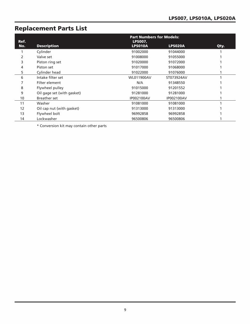
LPS007, LPS010A, LPS020A
Part Numbers for Models: Ref. LPS007, No. Description LPS010A LPS020A Qty.
1 Cylinder 91002000 91044000 1 2 Valve set 91008000 91055000 1 3 Piston ring set 91020000 91072000 1 4 Piston set 91017000 91068000 1 5 Cylinder head 91022000 91076000 1 6 Intake fi lter set WL011900AV ST073924AV 1 7 Filter element N/A 91348550 1 8 Flywheel pulley 91015000 91201552 1 9 Oil gage set (with gasket) 91281000 91281000 1 10 Breather set IP002100AV IP002100AV 1 11 Washer 91081000 91081000 1 12 Oil cap nut (with gasket) 91313000 91313000 1 13 Flywheel bolt 96992858 96992858 1 14 Lockwasher 96500806 96500806 1
* Conversion kit may contain other parts
Replacement Parts List
10
Lubricated Compressor Pumps
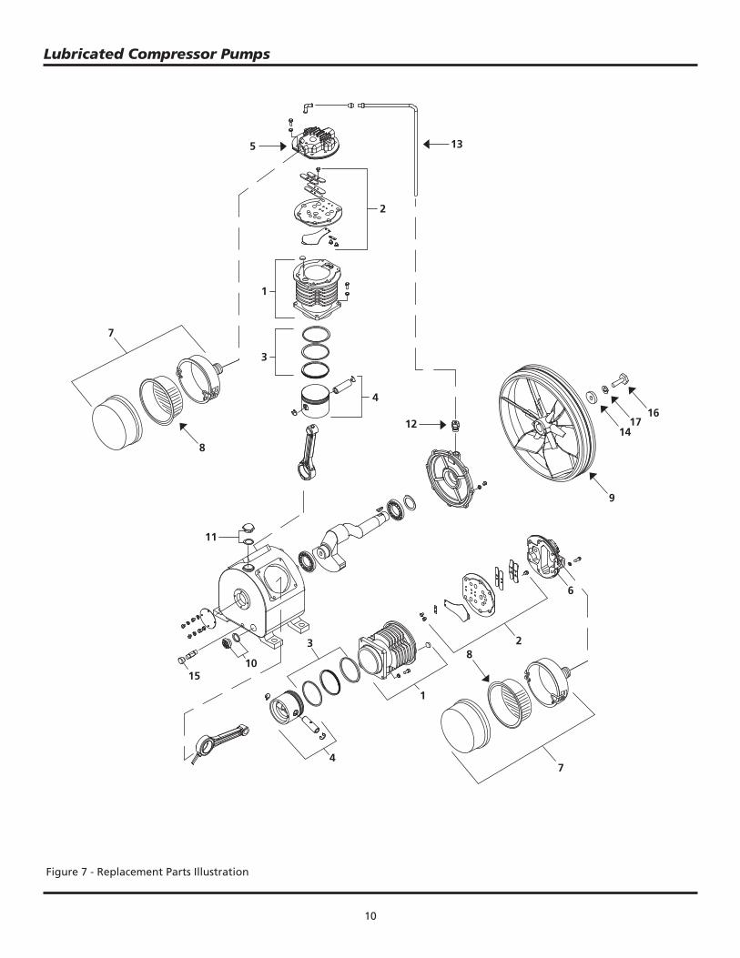
Figure 7 - Replacement Parts Illustration
135
2
7
1
3
4
8
12
9
1417
16
11
1510
3
4
1
8
7
2
6
11
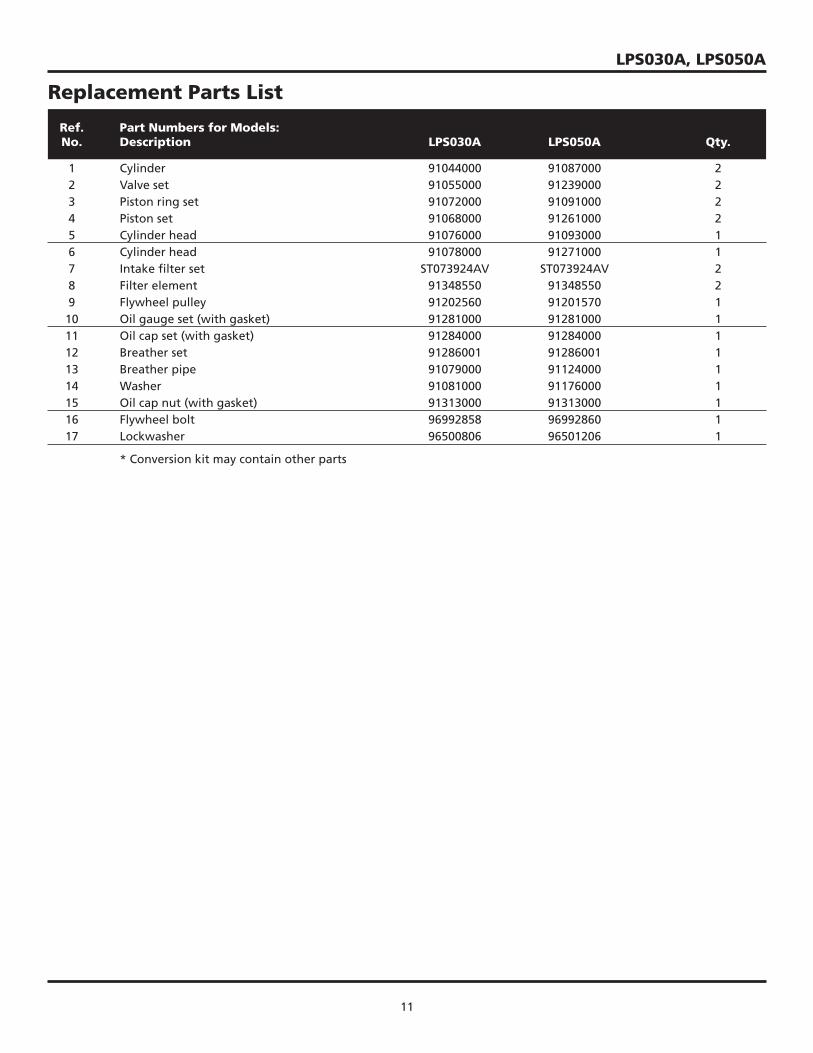
Ref. Part Numbers for Models: No. Description LPS030A LPS050A Qty.
1 Cylinder 91044000 91087000 2 2 Valve set 91055000 91239000 2 3 Piston ring set 91072000 91091000 2 4 Piston set 91068000 91261000 2 5 Cylinder head 91076000 91093000 1 6 Cylinder head 91078000 91271000 1 7 Intake fi lter set ST073924AV ST073924AV 2 8 Filter element 91348550 91348550 2 9 Flywheel pulley 91202560 91201570 1 10 Oil gauge set (with gasket) 91281000 91281000 1 11 Oil cap set (with gasket) 91284000 91284000 1 12 Breather set 91286001 91286001 1 13 Breather pipe 91079000 91124000 1 14 Washer 91081000 91176000 1 15 Oil cap nut (with gasket) 91313000 91313000 1 16 Flywheel bolt 96992858 96992860 1 17 Lockwasher 96500806 96501206 1
* Conversion kit may contain other parts
Replacement Parts List
LPS030A, LPS050A
12
Lubricated Compressor Pumps
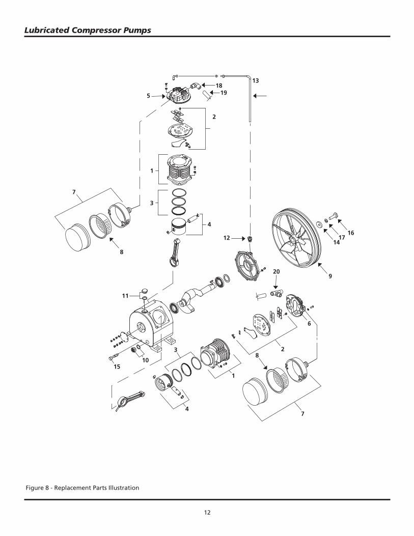
Figure 8 - Replacement Parts Illustration
1819
20
13
5
2
7
1
3
4
8
12
9
1417
16
11
1510
3
4
1
8
7
2
6
13
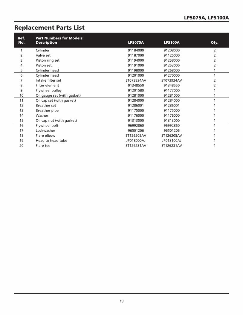
Ref. Part Numbers for Models: No. Description LPS075A LPS100A Qty.
1 Cylinder 91184000 91208000 2 2 Valve set 91187000 91125000 2 3 Piston ring set 91194000 91258000 2 4 Piston set 91191000 91253000 2 5 Cylinder head 91198000 91268000 1 6 Cylinder head 91201000 91270000 1 7 Intake fi lter set ST073924AV ST073924AV 2 8 Filter element 91348550 91348550 2 9 Flywheel pulley 91201580 91177000 1 10 Oil gauge set (with gasket) 91281000 91281000 1 11 Oil cap set (with gasket) 91284000 91284000 1 12 Breather set 91286001 91286001 1 13 Breather pipe 91175000 91175000 1 14 Washer 91176000 91176000 1 15 Oil cap nut (with gasket) 91313000 91313000 1 16 Flywheel bolt 96992860 96992860 1 17 Lockwasher 96501206 96501206 1 18 Flare elbow ST126205AV ST126205AV 1 19 Head to head tube JP018000AJ JP018100AJ 1 20 Flare tee ST126231AV ST126231AV 1
Replacement Parts List
LPS075A, LPS100A
14
Lubricated Compressor Pumps
Notes
15
LPS075A, LPS100A
Powerex Limited Warranty – Applicable to Non-OEM Customers in the U.S. & Canada Only
Warranty and Remedies.
(a) General. Powerex warrants each Compressor System, Vacuum System, Vacuum Pump, Compressor Air-End, or Powerex branded Accessory (collectively “Products”, individually each a “Product”) to be free from defects in material and workmanship (“Defects”) at the date of shipment. This warranty shall apply only to Products that are purchased and used in the United States of America and in Canada. EXCEPT AS SET FORTH BELOW, NO OTHER WARRANTY, WHETHER EXPRESS OR IMPLIED, INCLUDING ANYWARRANTY OF MERCHANTABILITY OR FITNESS FOR A PARTICULAR PURPOSE, SHALL EXIST IN CONNECTION WITH THE SALE OR USE OF SUCH PRODUCTS. TO THE EXTENT PERMITTED BY LAW, ANY AND ALL IMPLIED WARRANTIES ARE EXCLUDED. All warranty claims must be made in writing and delivered to Powerex in accordance with the procedures set forth on its website (www.powerexinc.com), or such claim shall be barred. Upon timely receipt of a warranty claim, Powerex shall inspect the Product claimed to have a Defect, and Powerex shall repair, or, at its option, replace, free of charge, any Product which it determines to have had a Defect; provided, however, that if circumstances are such as to preclude the remedying of Defect by repair or replacement, Powerex shall, upon return of the Product, refund to buyer any part of the purchase price of such Products paid to Powerex. Freight for returning Products to Powerex for inspection shall be paid by buyer. The warranties and remedies herein are the sole and exclusive remedy for any breach of warranty or for any other claim based on any Defect, or non-performance of the Products, whether based upon contract, warranty or negligence.(b) (i) Standard Period of Warranty – Parts and Labor - The purchase of any system includes our standard warranty. Powerex warrants and represents all Products shall be free from Defects for the fi rst eighteen (18) months from the date of shipment by Powerex, or twelve (12) months from the documented date of startup, or fi ve thousand (5,000) hours of use, whichever occurs fi rst. During such warranty period, Powerex shall be fully liable for all Defects in the Products (the “Product Defects”), i.e., all costs of repair or replacement, which may include “in and out” charges, so long as the Products are located in the United States or Canada, and the Products are reasonably located and accessible by service personnel for removal. “In and out” charges include the costs of removing a Product from buyer’s equipment for repair or replacement. (ii) Premium Period of Warranty – Parts and Labor - In order to be eligible for premium warranty coverage, a premium warranty for each system must be purchased when order is placed. Powerex warrants and represents all Products shall be free from Defects for the fi rst thirty (30) months from the date of shipment by Powerex, or twenty-four (24) months from the documented date of startup, or seven thousand fi ve hundred (7,500) hours of use, whichever occurs fi rst. During such warranty period, Powerex shall be fully liable for all Defects in the Products (the “Product Defects”), i.e., all costs of repair or replacement, which may include “in and out” charges, so long as the Products are located in the United States or Canada, and the Products are reasonably located and accessible by service personnel for removal. “In and out” charges include the costs of removing a Product from buyer’s equipment for repair or replacement.(c) Additional Period of Warranty – Parts Only (No Labor). In addition to the above, Powerex warrants each Powerex branded Compressor Air- End and Vacuum Pump shall be free of Defects for a period of forty-two (42) months from the date of shipment by Powerex, or thirty-six (36) months from the documented date of startup, or ten thousand (10,000) hours of use, whichever occurs fi rst. Supplier’s repair or replacement of any Product shall not extend the period of any warranty of any Product. This warranty applies to the exchange of part(s) found to be defective by an Authorized Powerex Service Representative only.(d) Replacement Pumps – Parts Only (No Labor). For any replacement Air-End or Vacuum Pumps installed on a Powerex manufactured system or unit after any initial warranty period has expired or where another warranty does not apply for any reason, Powerex warrants that the Air-End or Vacuum Pumps shall be free of Defects for a period of thirty-six (36) months from the date of shipment by Powerex or ten thousand (10,000)hours of use, whichever comes fi rst. For any replacement Air-End or Vacuum Pumps installed on a system that was not manufactured by Powerex after any initial warranty period has expired or where another warranty does not apply for any reason, Powerex warrants that the Air-End or Vacuum Pumps shall be free of Defects for the fi rst twelve (12) months from the date of shipment by Powerex. Supplier’s repair or replacement of any Product shall not extend the period of any warranty of any Product. This warranty applies to the exchange of part(s) found to be defective by an Authorized Powerex Service Representative only.(e) Replacement Motors – Parts Only (No Labor). For any replacement motor installed on a Powerex manufactured system or unit after any initial warranty period has expired or where another warranty does not apply for any reason, Powerex warrants that the replacement motor shall be free of Defects for the fi rst twelve (12) months from the date of shipment by Powerex. For any replacement motor installed on a system or unit that was not manufactured by Powerex after any initial warranty period has expired or where another warranty does not apply for any reason, Powerex warrants that the replacement motor shall be free of Defects for the fi rst ninety (90) days from the date of shipment by Powerex. Supplier’s repair or replacement of any Product shall not extend the period of any warranty of any Product. This warranty applies to the exchange of part(s) found to be defective by an Authorized Powerex Service Representative only.(f) Replacement Parts – Parts Only (No Labor). For other replacement parts besides motors, Air-End or Vacuum Pumps installed on a Powerex manufactured system or unit after any initial warranty period has expired or where another warranty does not apply for any reason, Powerex warrants that such replacement parts will be free from Defects for the fi rst twelve (12) months from the date of shipment by Powerex. For other replacement parts besides motors, Air-End or Vacuum Pumps installed on a system or unit that was not manufactured by Powerex after any initial warranty period has expired or where another warranty does not apply for any reason, Powerex makes no warranties. Supplier’s repair or replacement of any Product shall not extend the period of any warranty of any Product. This warranty applies to the exchange of part(s) found to be defective by an Authorized Powerex Service Representative only.(g) Coverage. The warranty provided herein applies to Powerex manufactured units or systems only.(h) Exceptions. Notwithstanding anything to the contrary herein, Powerex shall have no warranty obligations with respect to Products:
(i) that have not been installed in accordance with Powerex’s written specifi cations and instructions;(ii) that have not been maintained in accordance with Powerex’s written instructions;(iii) that have been materially modifi ed without the prior written approval of Powerex; or(iv) that experience failures resulting from operation, either intentional or otherwise, in excess of rated capacities or in an otherwise
improper manner.
Powerex • 150 Production Drive • Harrison, OH 45030 • USA1-888-769-7979 • www.powerexinc.com 16
Lubricated Compressor Pumps
(i) The warranty provided herein shall not apply to:(i) any defects arising from corrosion, abrasion, use of insoluble lubricants, or negligent attendance to or faulty operation of the
Products;(ii) ordinary wear and tear of the Products; (iii) defects arising from abnormal conditions of temperature, dirt or corrosive matter; or (iv) any OEM component which is shipped by Powerex with the original manufacturer’s warranty, which shall be the sole applicable
warranty for such component.Limitation of Liability. NOTWITHSTANDING ANYTHING TO THE CONTRARY HEREIN, TO THE EXTENT ALLOWABLE UNDER APPLICABLE LAW, UNDER NO CIRCUMSTANCES SHALL POWEREX BE LIABLE FOR ANY INCIDENTAL, CONSEQUENTAL, PUNITIVE, SPECULATIVE OR INDIRECT LOSSES OR DAMAGES WHATSOEVER ARISING OUT OF OR IN ANY WAY RELATED TO ANY OF THE PRODUCTS OR GOODS SOLD OR AGREED TO BE SOLD BY POWEREX TO BUYER. TO THE EXTENT ALLOWABLE UNDER APPLICABLE LAW, POWEREX’S LIABILITY IN ALL EVENTS IS LIMITED TO, AND SHALL NOT EXCEED, THE PURCHASE PRICE PAID.Warranty Disclaimer. Powerex has made a diligent effort to illustrate and describe the Products in its literature, including its Price Book,accurately; however, such illustrations and descriptions are for the sole purpose of identifi cation, and do not express or imply a warranty that the Products are merchantable, or fi t for a particular purpose, or that the Products will necessarily conform to the illustrations or descriptions.Product Suitability. Many jurisdictions have codes and regulations governing sales, construction, installation, and/or use of Products for certain purposes, which may vary from those in neighboring areas. While Powerex attempts to assure that its Products comply with such codes, it cannot guarantee compliance, and cannot be responsible for how the product is installed or used. Before purchase and use of a Product, please review the Product applications, and national and local codes and regulations, and be sure that the Product, installation, and use will comply with them.Claims. Any non-warranty claims pertaining to the Products must be fi led with Powerex within 6 months of the invoice date, or they will not be honored. Prices, discounts, and terms are subject to change without notice or as stipulated in specifi c Product quotations. Powerex shall not be liable for any delay or failure arising out of acts of the public enemy, fi re, fl ood, or any disaster, labor trouble, riot or disorder, delay in the supply of materials or any other cause, whether similar or dissimilar, beyond the control of Company. All shipments are carefully inspected and counted before leaving the factory. Please inspect carefully any receipt of Products noting any discrepancy or damage on the carrier’s freight bill at the time of delivery. Discrepancies or damage which obviously occurred in transit are the carrier’s responsibility and related claims should be made promptly directly to the carrier. Returned Products will not be accepted without prior written authorization by Powerex and deductions from invoices for shortage or damage claims will not be allowed. UNLESS OTHERWISE AGREED TO IN WRITING, THE TERMS AND CONDITIONS CONTAINED IN THIS LIMITED WARRANTY WILL CONTROL IN ANY TRANSACTION WITH POWEREX. Any different or confl icting terms as may appear on any order form now or later submitted by the buyer will not control. All orders are subject to acceptance by Powerex.


![Pressure Balanced Lubricated Plug Valves - API 6D Short ... · PDF fileSCV Pressure Balanced Lubricated Plug Valves - API 6D [Product Preview ] Pressure Balanced Lubricated Plug Valves](https://img.pdfslide.net/doc/110x75/5a9e06877f8b9a4a238da7ee/pressure-balanced-lubricated-plug-valves-api-6d-short-scv-pressure-balanced.jpg)