Embed Size (px)
Citation preview
Low Noise CMOS Simulation of Outer Hair Cell Activity in the
M li C hlMammalian Cochlea
K A R E N J U Z S W I KR O B E R T L I T T R E L L
E D W A R D T A N GE D W A R D T A N G
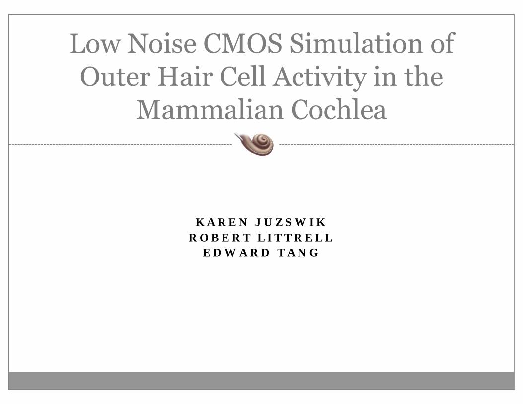
Cochlea & MEMS Transducer
Picture courtesy of NSF
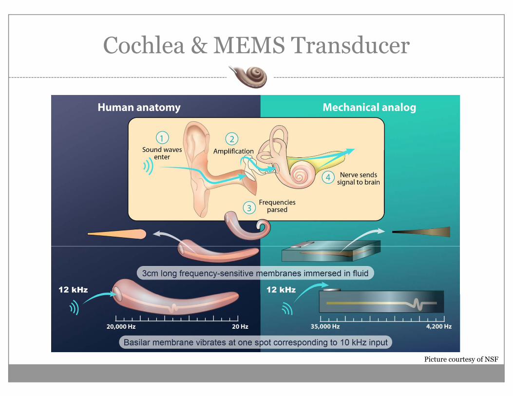
Outer Hair Cells
Tectorial Membrane
Inner Hair Cell
Basilar Membrane•Outer Hair Cell Feedback
Basilar Membrane•Enhance Sensitivity
•Tectorial Membrane & OHC Outer Hair Cell•2nd Order System Model
•Inner Hair Cell Sensing
Animation courtesy of http://147.162.36.50/cochlea/cochleapages/theory/main.htm
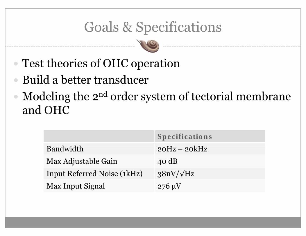
Goals & Specificationsp
T t th i f OHC tiTest theories of OHC operationBuild a better transducerModeling the 2nd order system of tectorial membrane and OHC
Specifications
B d idth H kHBandwidth 20Hz – 20kHz
Max Adjustable Gain 40 dB
Input Referred Noise (1kHz) 38nV/√HzInput Referred Noise (1kHz) 38nV/√Hz
Max Input Signal 276 µV
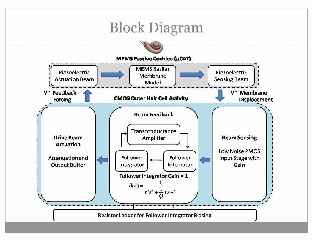
Block Diagramg
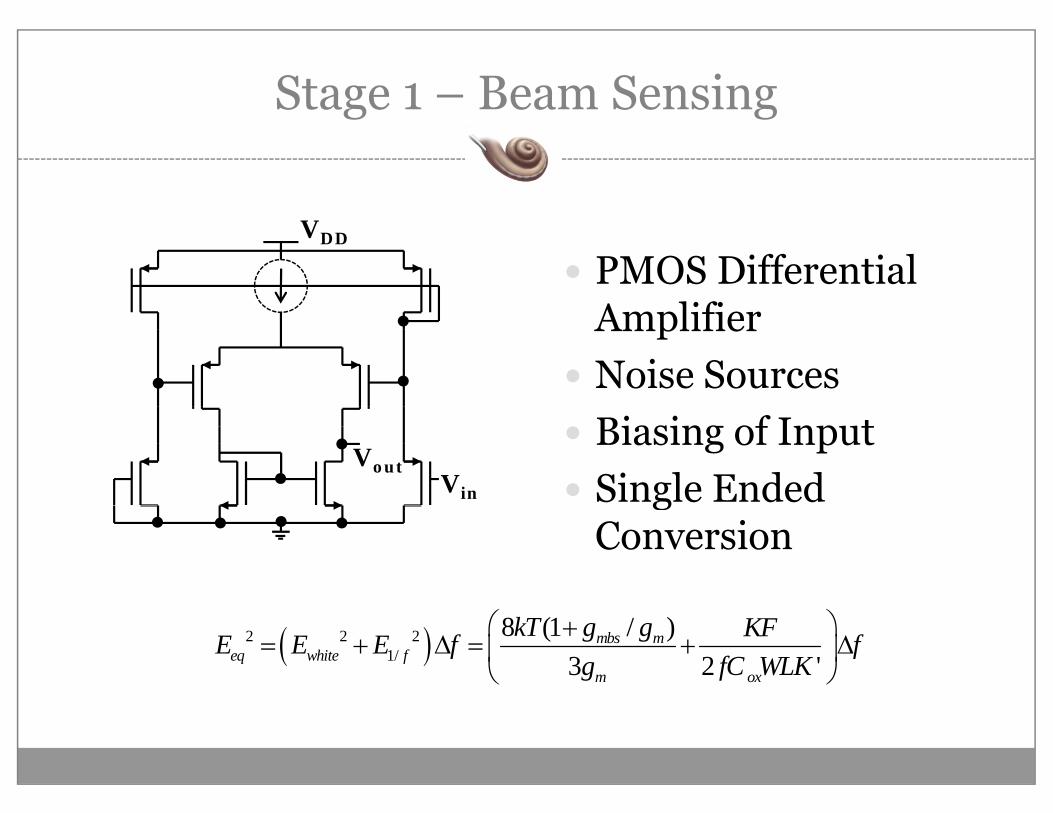
Stage 1 – Beam Sensingg g
PMOS Differential A lifi
VDD
AmplifierNoise SourcesBiasing of InputSingle Ended Vin
Vout
gConversion
( )2 2 21/
8 (1 / )3 2 '
mbs meq white f
m ox
kT g g KFE E E f fg fC WLK
⎛ ⎞+= + Δ = + Δ⎜ ⎟
⎝ ⎠
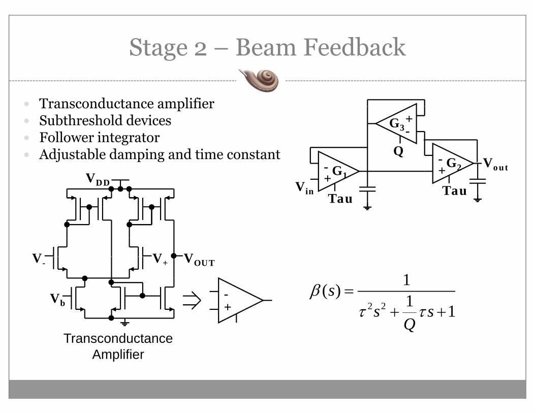
Stage 2 – Beam Feedbackg
Transconductance amplifierTransconductance amplifierSubthreshold devicesFollower integratorAdjustable damping and time constant
+-
Q
G3
Adjustable damping and time constant
VDD+-
+-
Vin
Vout
Q
Tau TauG1
G2
V V VV- V+
Vb
VOUT
+-
2 2
1( ) 1 1sβ =
+ 2 2 1s sQ
τ τ+ +
Transconductance AmplifierAmplifier
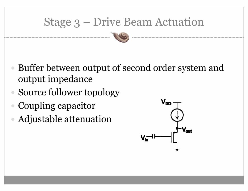
Stage 3 – Drive Beam Actuationg 3
Buffer between output of second order system and p youtput impedanceSource follower topologyp gyCoupling capacitorAdjustable attenuationAdjustable attenuation
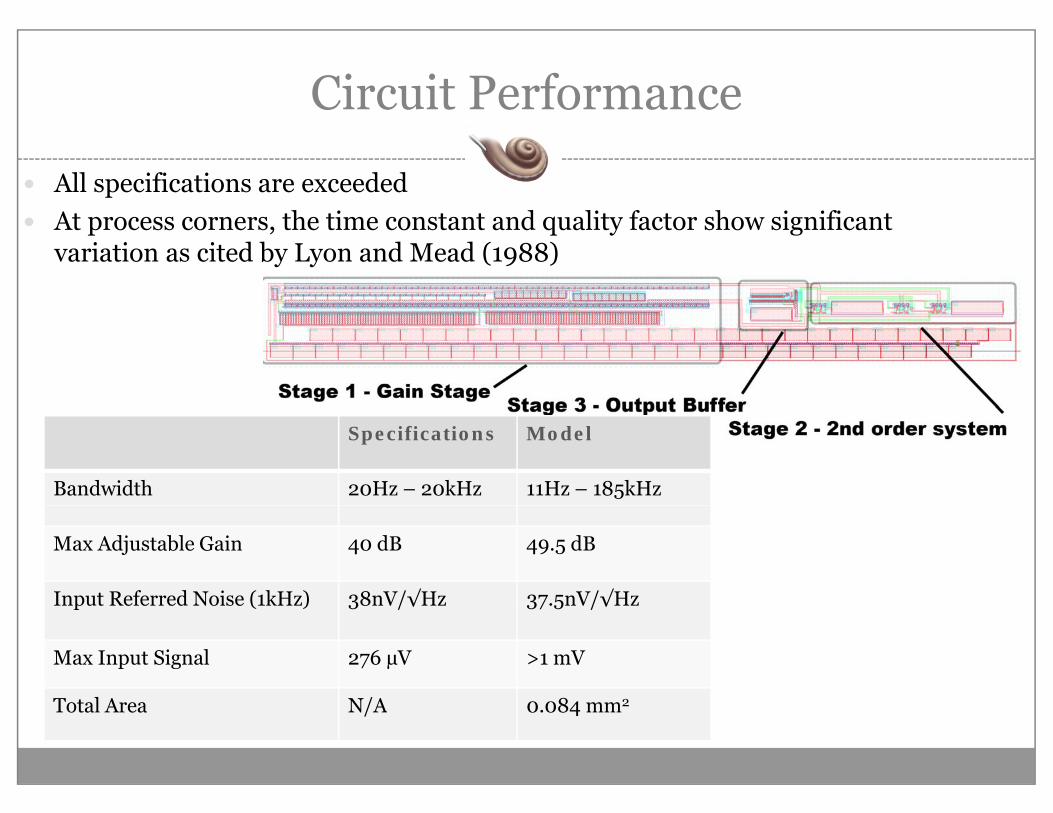
Circuit Performance
All specifications are exceededAt process corners, the time constant and quality factor show significant variation as cited by Lyon and Mead (1988)
Specifications Model
Bandwidth 20Hz – 20kHz 11Hz – 185kHz
Max Adjustable Gain 40 dB 49.5 dB
Input Referred Noise (1kHz) 38nV/√Hz 37.5nV/√HzInput Referred Noise (1kHz) 38nV/√Hz 37.5nV/√Hz
Max Input Signal 276 µV >1 mV
Total Area N/A 0 084 mm2Total Area N/A 0.084 mm2
Circuit Performance
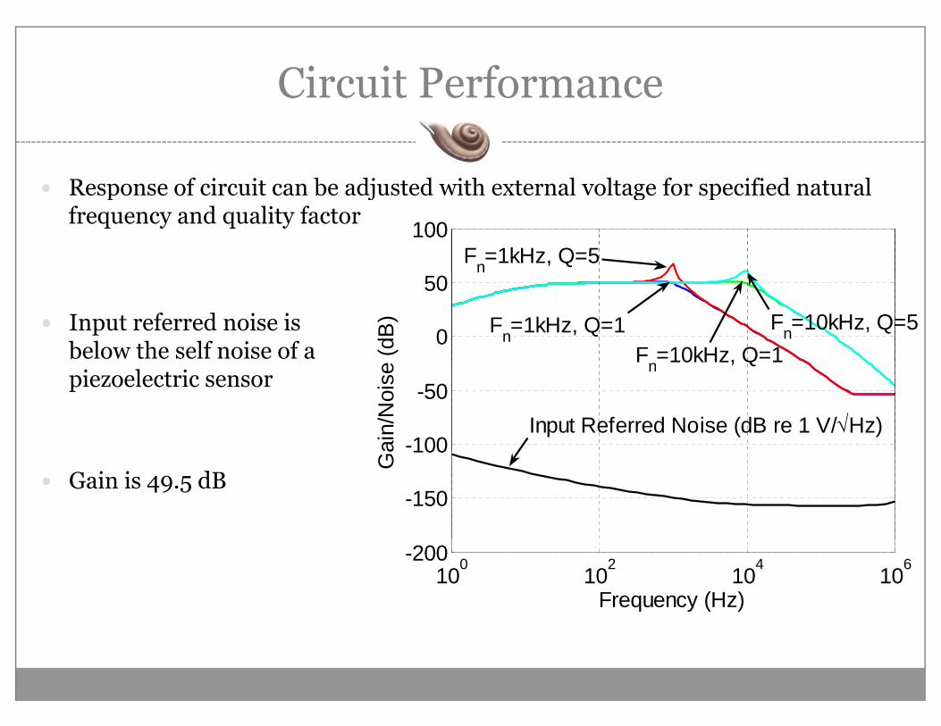
Response of circuit can be adjusted with external voltage for specified natural Response of circuit can be adjusted with external voltage for specified natural frequency and quality factor
0
100Fn=1kHz, Q=5
0
50
e (d
B) Fn=1kHz, Q=1 Fn=10kHz, Q=5
Fn=10kHz, Q=1Input referred noise is below the self noise of a
-100
-50ai
n/N
oise
Input Referred Noise (dB re 1 V/√Hz)
n , Qpiezoelectric sensor
-150
100
Ga
Gain is 49.5 dB
100 102 104 106-200
Frequency (Hz)
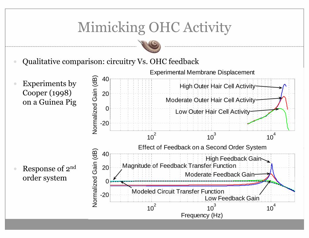
Mimicking OHC Activityg y
Qualitative comparison: circuitry Vs OHC feedbackQualitative comparison: circuitry Vs. OHC feedback
40
n (d
B) Experimental Membrane Displacement
High Outer Hair Cell ActivityExperiments by C ( 8)
0
20al
ized
Gai
nModerate Outer Hair Cell Activity
Low Outer Hair Cell Activity
Cooper (1998) on a Guinea Pig
102 103 104
-20
Nor
ma
Effect of Feedback on a Second Order System
20
40
d G
ain
(dB
) Effect of Feedback on a Second Order System
High Feedback Gain
Moderate Feedback GainMagnitude of Feedback Transfer FunctionResponse of 2nd
order system
2 3 4
-20
0
Nor
mal
ized
Low Feedback GainModeled Circuit Transfer Function
order system
102 103 104
Frequency (Hz)
N
Questions?Questions?