Embed Size (px)
Citation preview
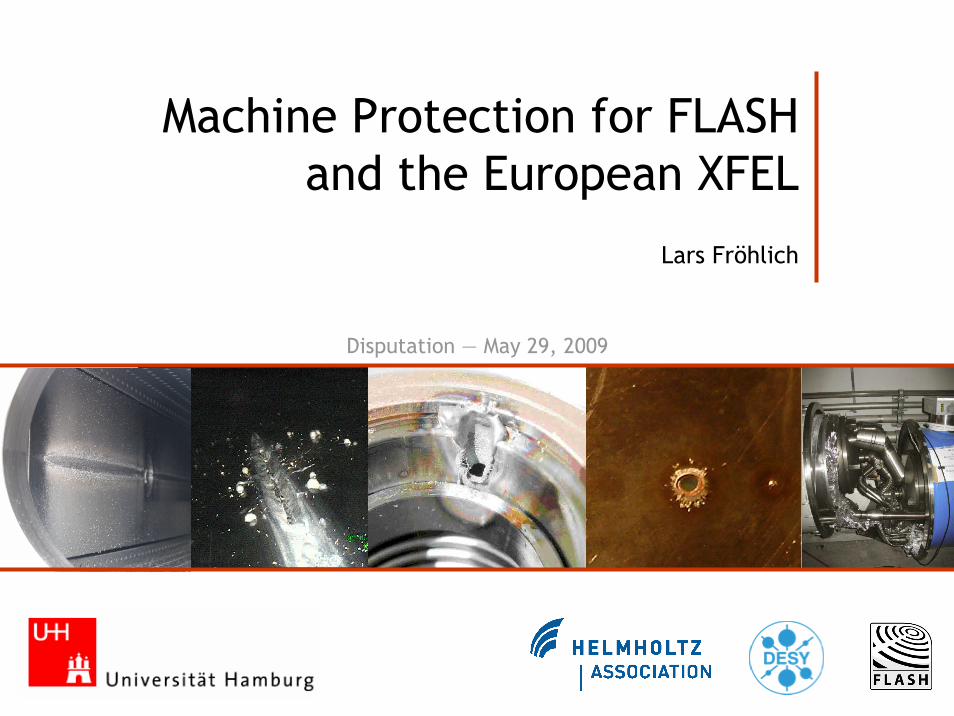
Machine Protection for FLASH and the European XFEL
Lars Fröhlich
Disputation — May 29, 2009
2
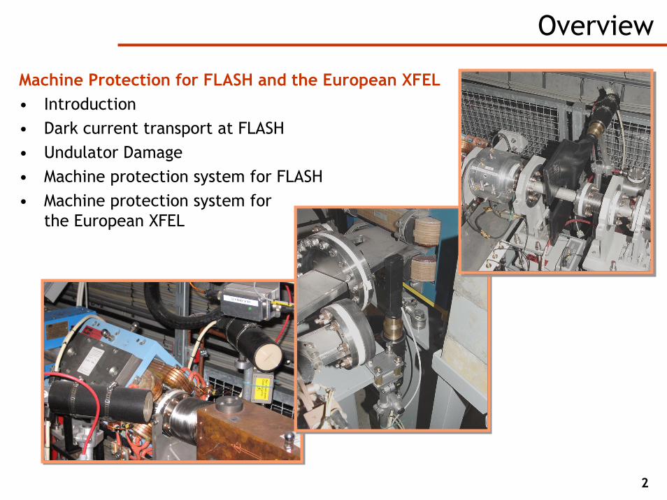
Overview
Machine Protection for FLASH and the European XFEL• Introduction• Dark current transport at FLASH• Undulator Damage• Machine protection system for FLASH• Machine protection system for
the European XFEL
3
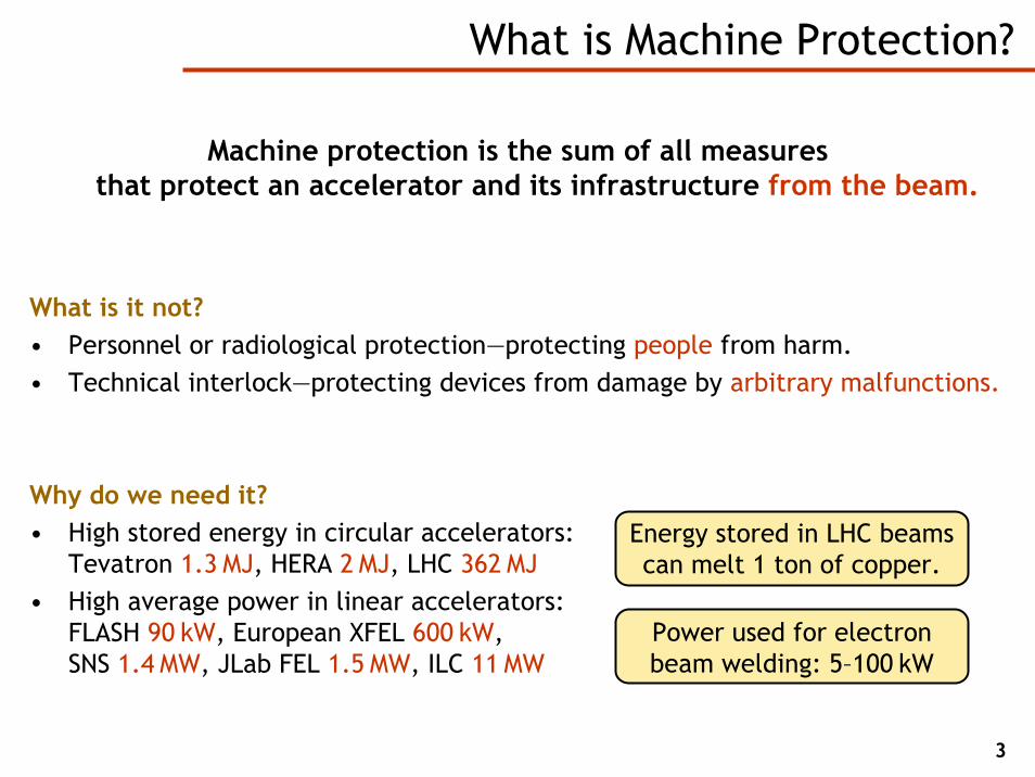
Machine protection is the sum of all measuresthat protect an accelerator and its infrastructure from the beam.
What is it not?• Personnel or radiological protection—protecting people from harm.• Technical interlock—protecting devices from damage by arbitrary malfunctions.
Why do we need it?• High stored energy in circular accelerators:
Tevatron 1.3 MJ, HERA 2 MJ, LHC 362 MJ• High average power in linear accelerators:
FLASH 90 kW, European XFEL 600 kW,SNS 1.4 MW, JLab FEL 1.5 MW, ILC 11 MW
What is Machine Protection?
Energy stored in LHC beams can melt 1 ton of copper.
Power used for electron beam welding: 5–100 kW
4
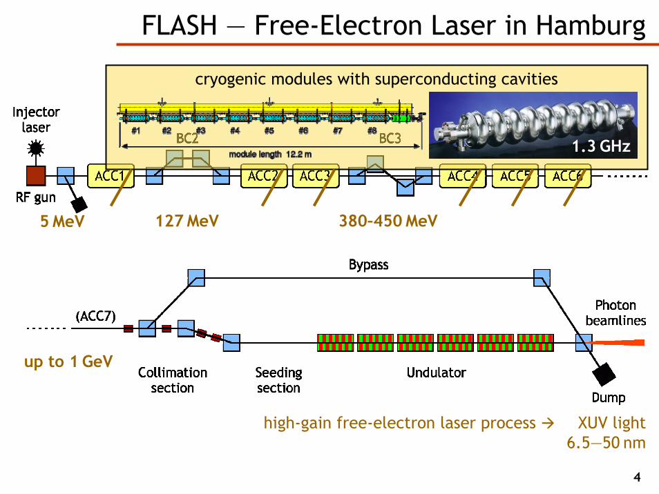
FLASH — Free-Electron Laser in Hamburg
127 MeV 380–450 MeV
up to 1 GeV
5 MeV
1.3 GHz
cryogenic modules with superconducting cavities
high-gain free-electron laser process XUV light6.5—50 nm
5
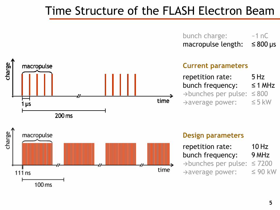
Current parameters
repetition rate: 5 Hzbunch frequency: ≤ 1 MHz
bunches per pulse: ≤ 800 average power: ≤ 5 kW
Time Structure of the FLASH Electron Beam
Design parameters
repetition rate: 10 Hzbunch frequency: 9 MHz
bunches per pulse: ≤ 7200 average power: ≤ 90 kW
bunch charge: ~1 nCmacropulse length: ≤ 800 µs

Dark Current Transport at FLASH
7
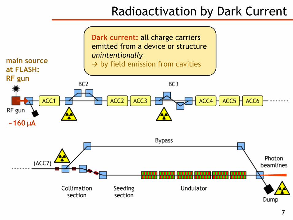
Radioactivation by Dark Current
Dark current: all charge carriers emitted from a device or structure unintentionally
by field emission from cavitiesmain source at FLASH:RF gun
~160 µA

8
The FLASH RF Gun
• Normal conducting 1½ cell copper cavity
• Exchangeable photocathode with high quantum efficiency
rfwave
9
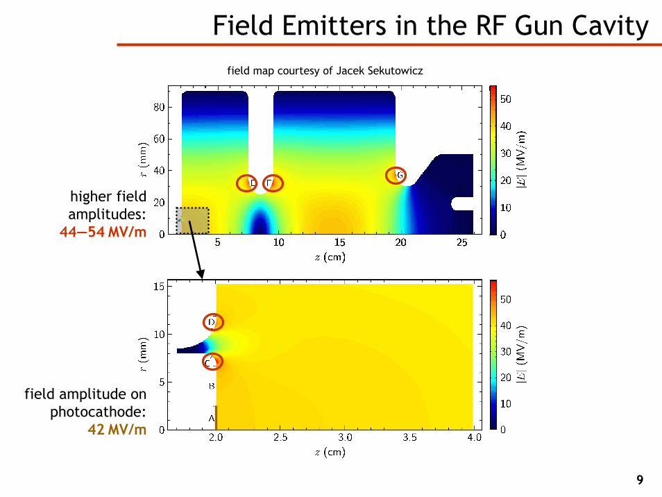
Field Emitters in the RF Gun Cavityfield map courtesy of Jacek Sekutowicz
field amplitude on photocathode:
42 MV/m
higher field amplitudes:
44—54 MV/m

10
Dark Current Transport in the RF Gun Cavity
Tracking of dark current from emitter surfaces(with enhanced Astra code for complex 3D geometries)
11
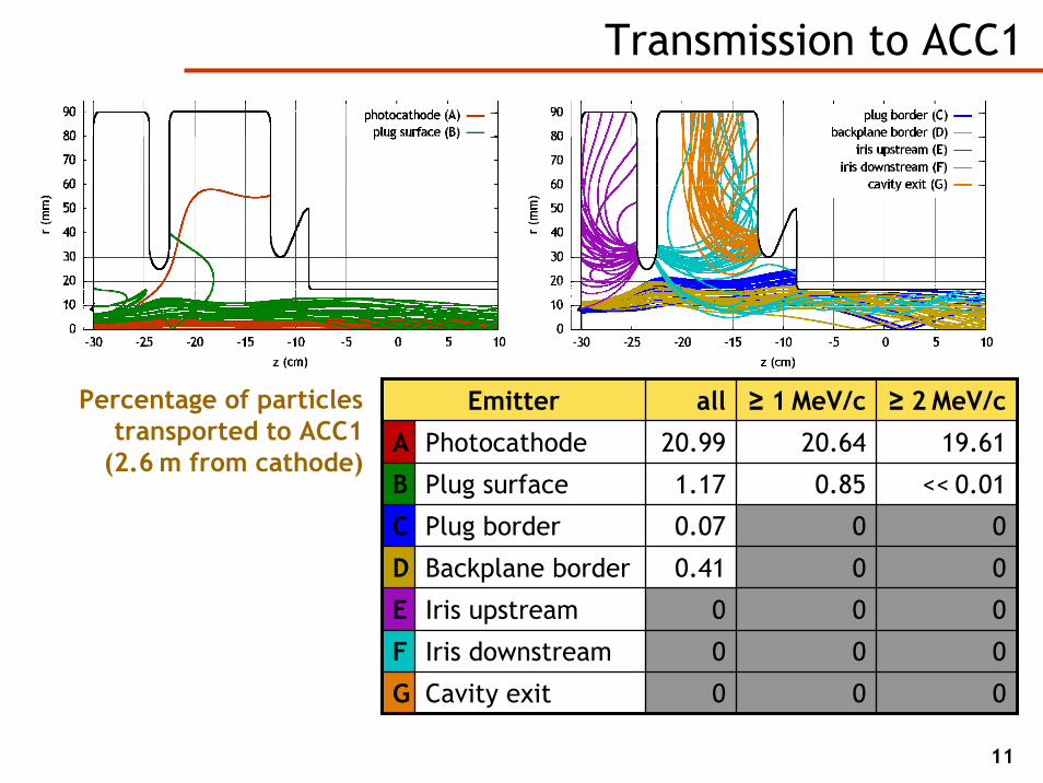
Transmission to ACC1
Emitter all ≥ 1 MeV/c ≥ 2 MeV/c
A Photocathode 20.99 20.64 19.61
B Plug surface
Plug border
Backplane border
Iris upstream
F Iris downstream 0 0 0
Cavity exit
1.17 0.85 << 0.01
C 0.07 0 0
D 0.41 0 0
E 0 0 0
G 0 0 0
Percentage of particles transported to ACC1
(2.6 m from cathode)

12
Overview
Location of majordark current losses:• behind rf gun• bunch compressor 2• bunch compressor 3• transverse collimators
Simulation parameters:• final beam energy:
980 MeV• ACC1 rf phase:
8° off-crest• ACC2—3 rf phase:
20° off-crest
30 W72 W29 W43 W2 W dark current power deposition(10 Hz, 800 µs pulse length)

Undulator Damage
14
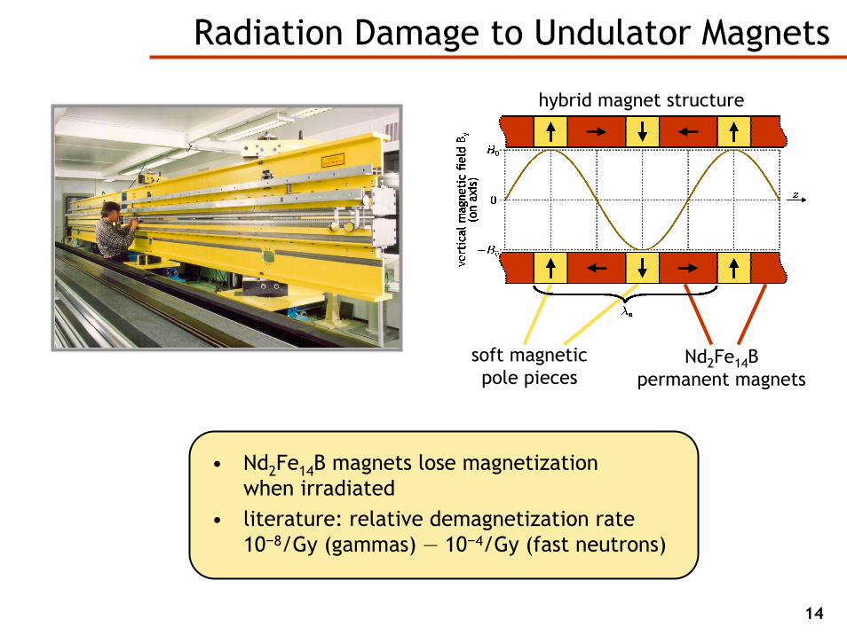
Radiation Damage to Undulator Magnets
• Nd2Fe14B magnets lose magnetizationwhen irradiated
• literature: relative demagnetization rate 10−8/Gy (gammas) — 10−4/Gy (fast neutrons)
hybrid magnet structure
Nd2Fe14Bpermanent magnets
soft magnetic pole pieces
15
diagnostic undulator
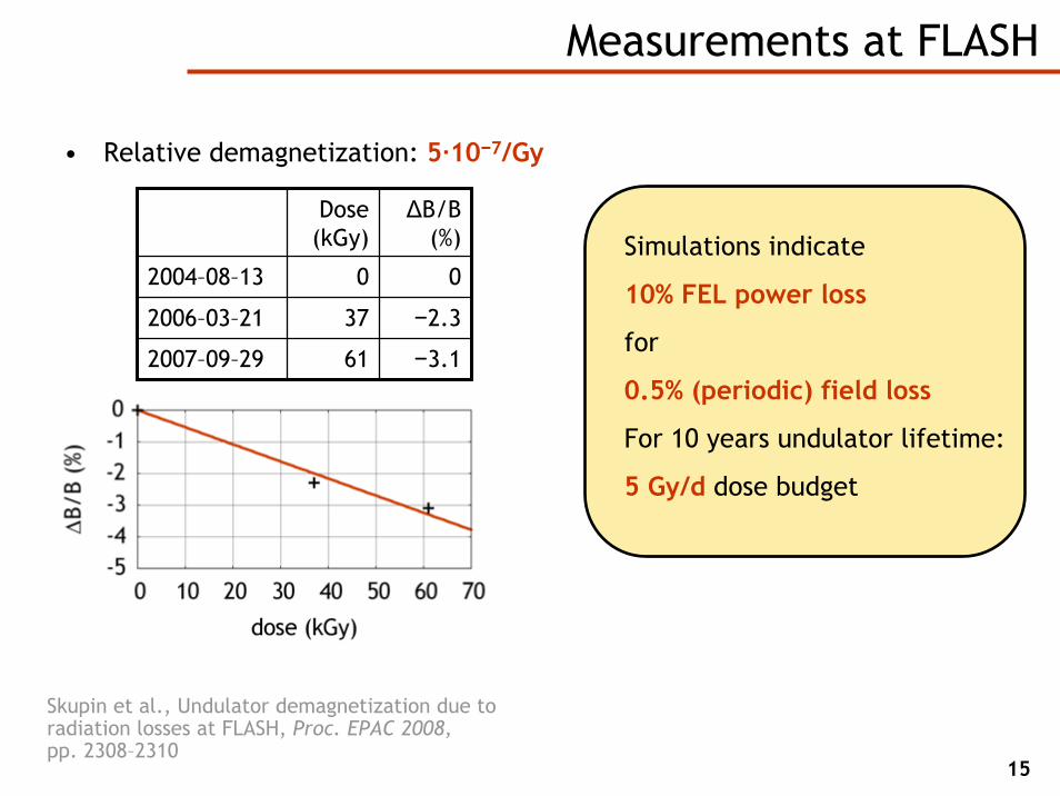
• Relative demagnetization: 5·10−7/Gy
Dose(kGy)
ΔB/B(%)
2004–08–13 0 0
2006–03–21 37 −2.3
2007–09–29 61 −3.1
Measurements at FLASH
Skupin et al., Undulator demagnetization due to radiation losses at FLASH, Proc. EPAC 2008,pp. 2308–2310
Simulations indicate
10% FEL power loss
for
0.5% (periodic) field loss
For 10 years undulator lifetime:
5 Gy/d dose budget

16
Undulator Beamline Model
diagnostic undulator
quadrupole magnets
shielding
FEL undulators Geometry model for the multi-particle transport code Fluka
17
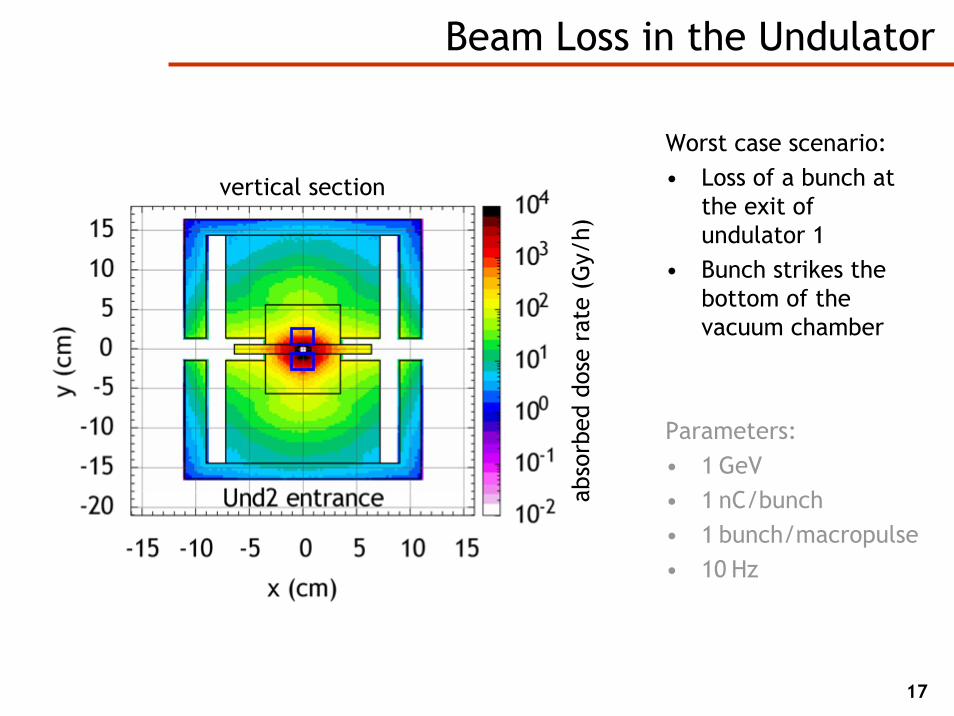
Beam Loss in the Undulator
Worst case scenario:• Loss of a bunch at
the exit of undulator 1
• Bunch strikes the bottom of the vacuum chamber
Parameters:• 1 GeV• 1 nC/bunch• 1 bunch/macropulse• 10 Hz
vertical section
abso
rbed
dos
e ra
te (
Gy/
h)
18
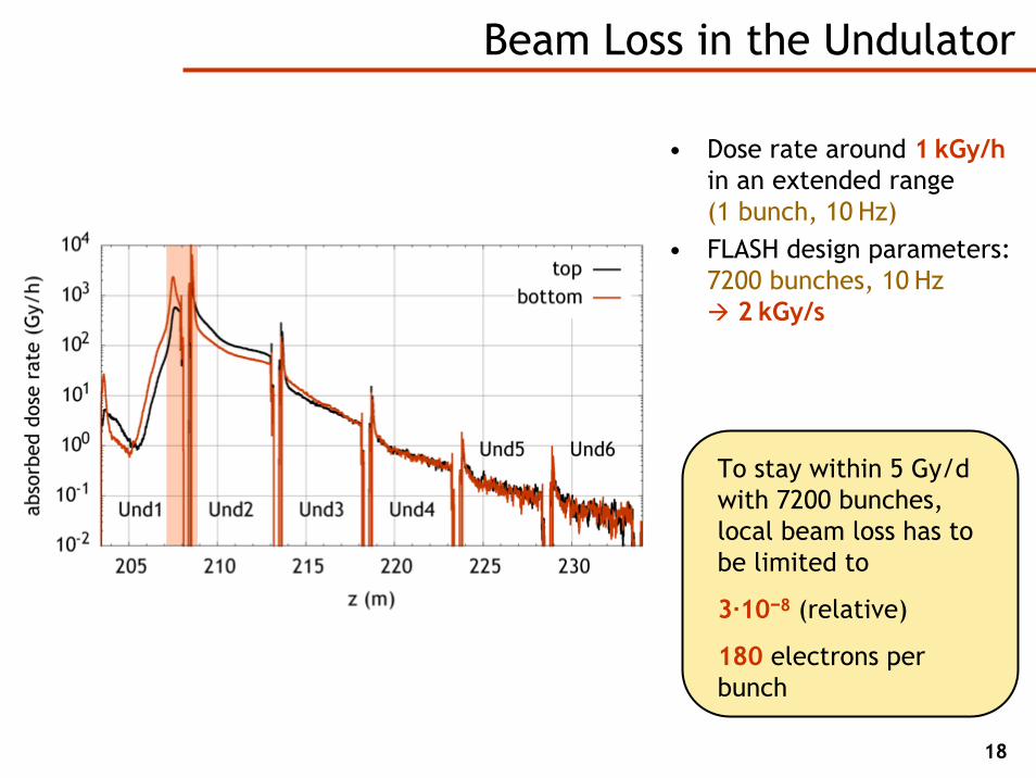
Beam Loss in the Undulator
• Dose rate around 1 kGy/hin an extended range(1 bunch, 10 Hz)
• FLASH design parameters:7200 bunches, 10 Hz
2 kGy/s
To stay within 5 Gy/d with 7200 bunches, local beam loss has to be limited to
3·10−8 (relative)
180 electrons per bunch
FLASH Machine Protection System
20
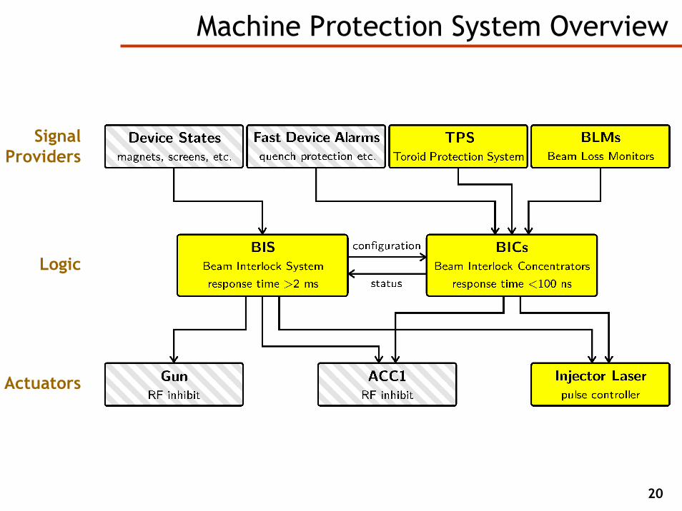
Machine Protection System Overview
Signal Providers
Actuators
Logic
21
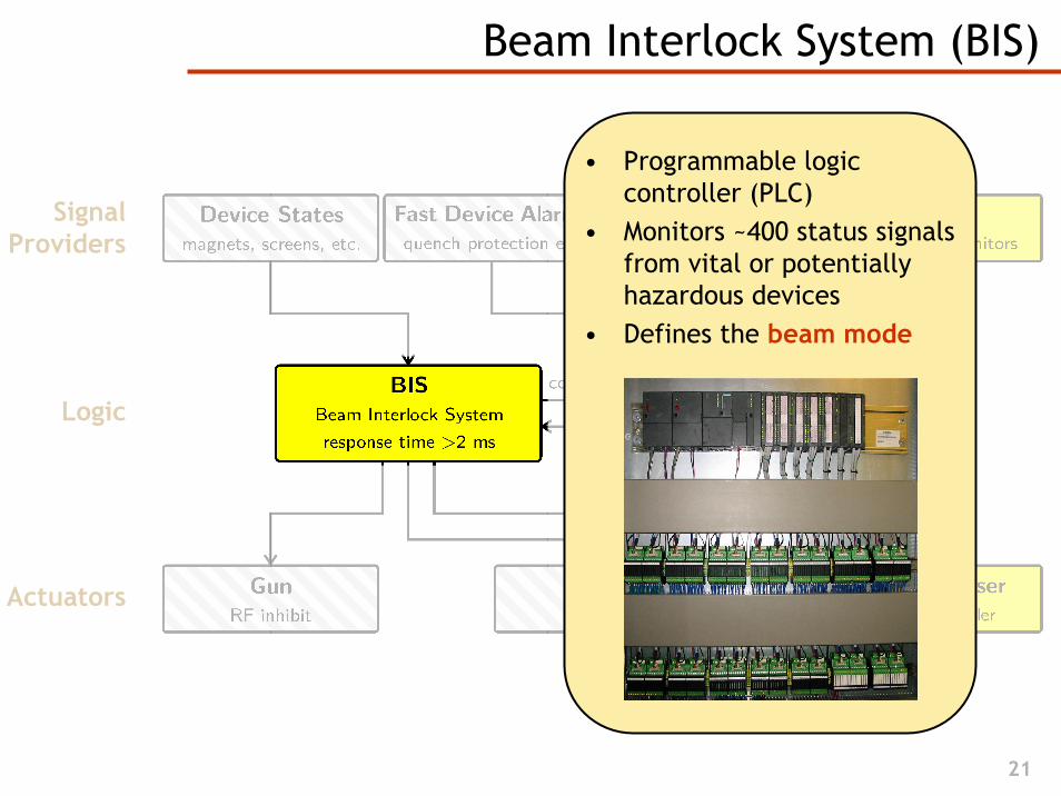
Beam Interlock System (BIS)
Signal Providers
Actuators
Logic
• Programmable logic controller (PLC)
• Monitors ~400 status signals from vital or potentially hazardous devices
• Defines the beam mode

22
Beam Interlock System: Beam Mode
operator chooses
BIS limits to
bunch limit
fast intra-trainprotection
single 2
short 30
long ∞

23
Beam Interlock Concentrators (BICs)
Signal Providers
Actuators
Logic
• Custom FPGA-controlled devices
• Function: logical OR for alarm signals
• Interruption of bunch production within the current macropulse
24
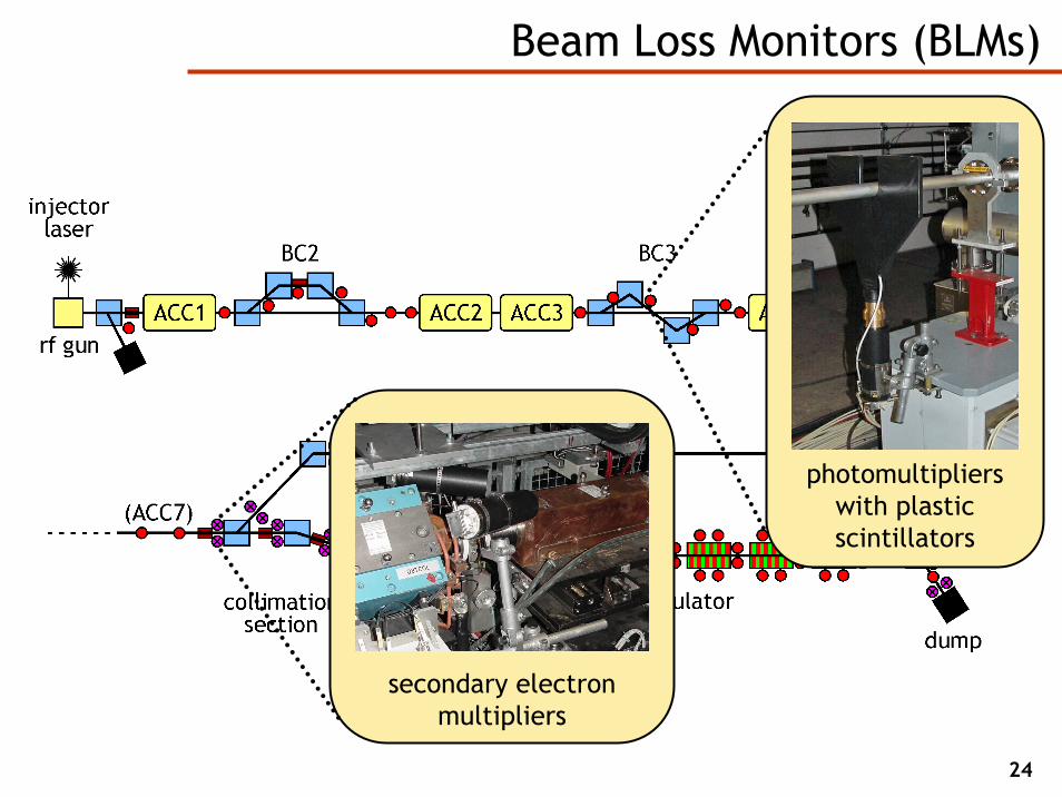
Beam Loss Monitors (BLMs)
photomultipliers with plastic scintillators
secondary electron multipliers

25
Algorithms for the Setup of the BLM System
• Passive configuration plausibility check
• Active cable test• Input offset setup• ADC sampling point setup• Integrator timing setup• ADC offset setup• BLM calibration by induced
beam loss• BLM calibration by wirescan• &c.
• Passive configuration plausibility check
• Active cable test• Input offset setup• ADC sampling point setup• Integrator timing setup• ADC offset setup• BLM calibration by induced
beam loss• BLM calibration by wirescan• &c.

26
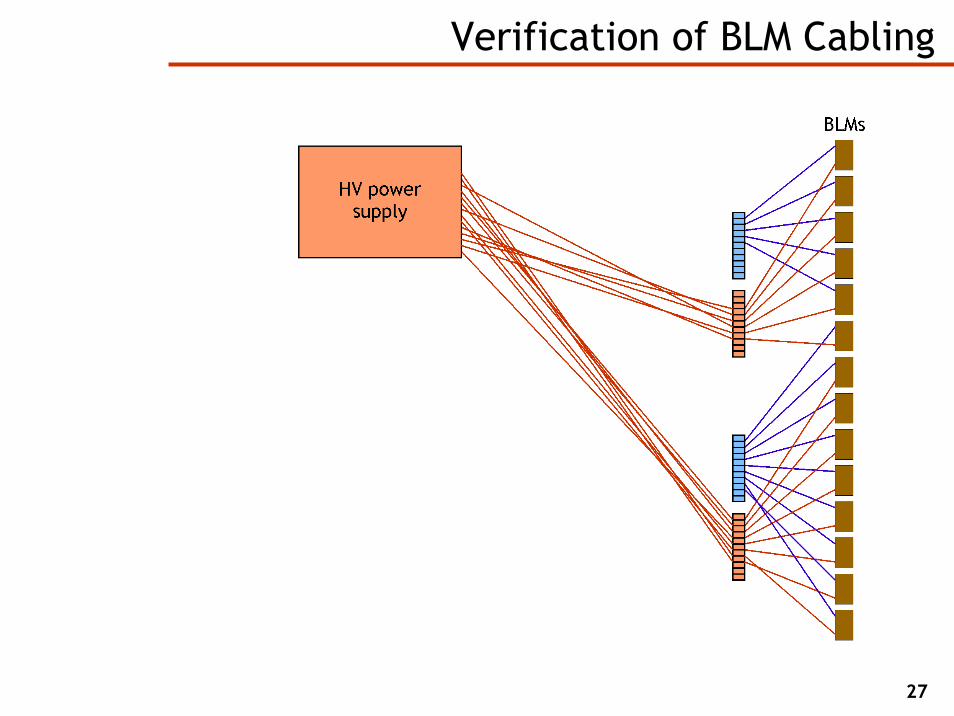
Verification of BLM Cabling
signa
l
highvoltage
27
Verification of BLM Cabling
28
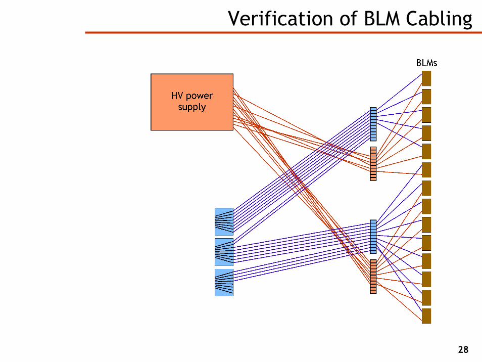
Verification of BLM Cabling

29
Verification of BLM Cabling
30
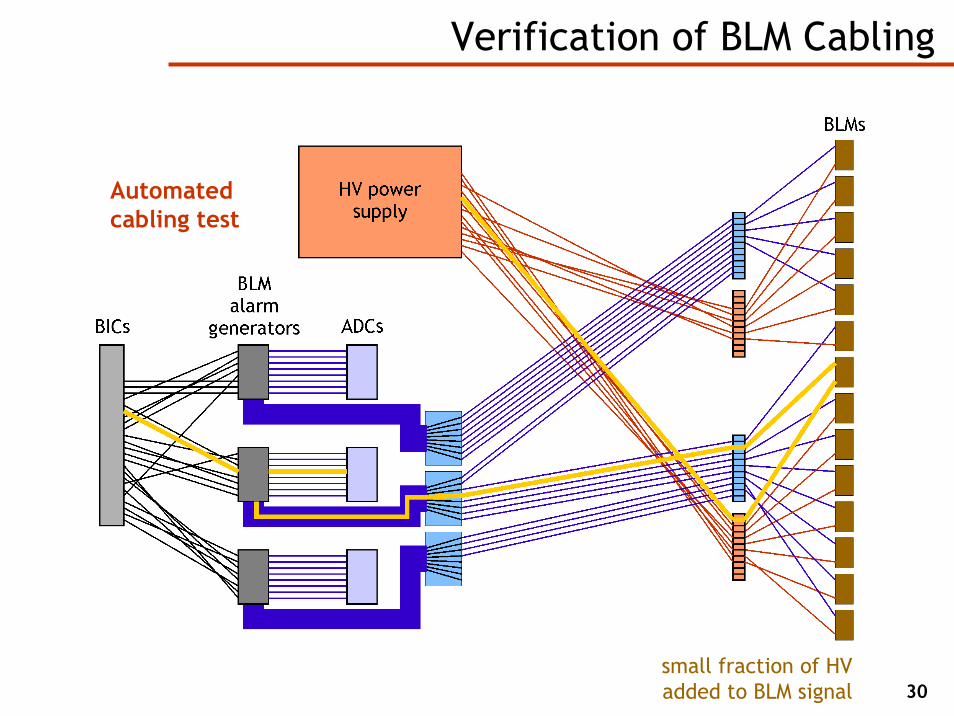
Verification of BLM Cabling
Automatedcabling test
small fraction of HVadded to BLM signal
31
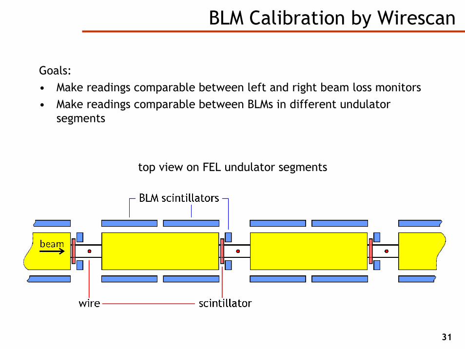
BLM Calibration by Wirescan
top view on FEL undulator segments
Goals:• Make readings comparable between left and right beam loss monitors• Make readings comparable between BLMs in different undulator
segments
32
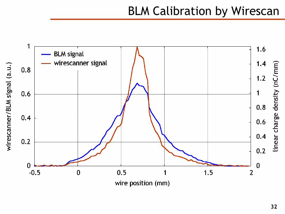
BLM Calibration by Wirescan
33
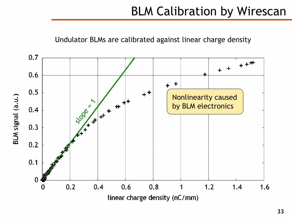
BLM Calibration by Wirescan
Undulator BLMs are calibrated against linear charge density
slope
= 1
Nonlinearity caused by BLM electronics

An MPS for the European XFEL

35
The European X-Ray Free-Electron Laser (XFEL)
final energy: 17.5 GeVFEL wavelength: down to 0.1 nm
accelerator length: 3 kmbunch frequency: 5 MHz
repetition rate: 10 Hz
50 bunches in the accelerator75 injected during signal
propagation (2/3 c)
125 bunches lost (22 kW)
36
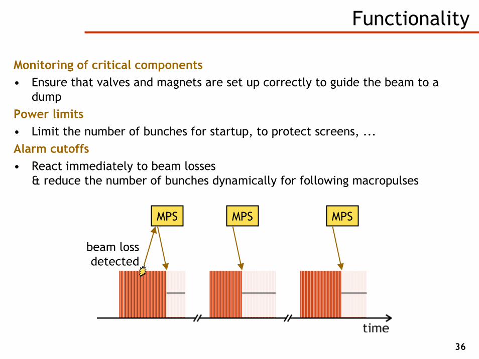
Functionality
Monitoring of critical components• Ensure that valves and magnets are set up correctly to guide the beam to a
dumpPower limits• Limit the number of bunches for startup, to protect screens, ...Alarm cutoffs• React immediately to beam losses
& reduce the number of bunches dynamically for following macropulses
beam loss detected
MPS MPS MPS
37
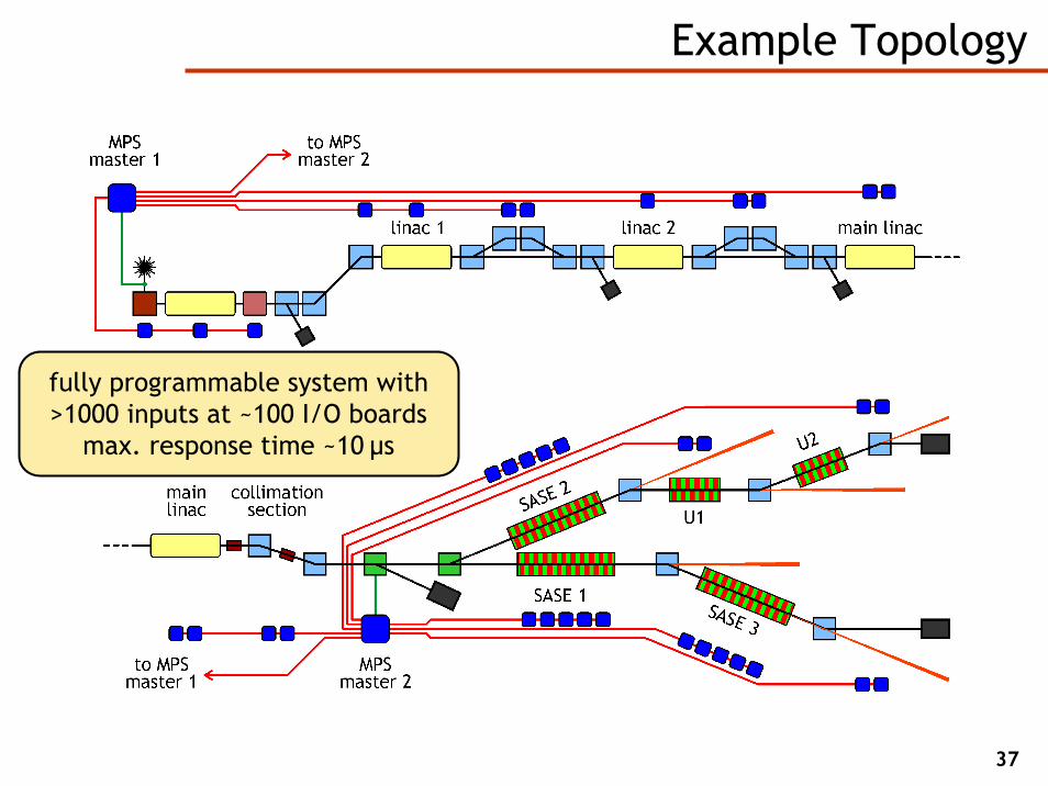
Example Topology
fully programmable system with>1000 inputs at ~100 I/O boards
max. response time ~10 µs

Conclusion
39
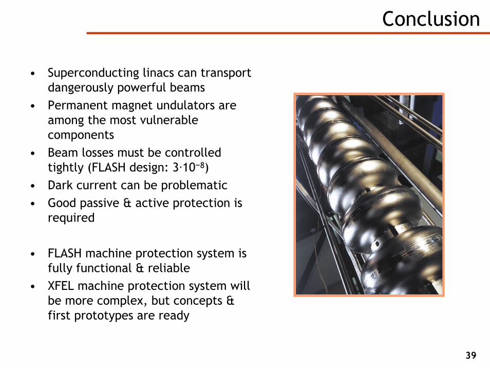
Conclusion
• Superconducting linacs can transport dangerously powerful beams
• Permanent magnet undulators are among the most vulnerable components
• Beam losses must be controlled tightly (FLASH design: 3·10−8)
• Dark current can be problematic• Good passive & active protection is
required
• FLASH machine protection system is fully functional & reliable
• XFEL machine protection system will be more complex, but concepts & first prototypes are ready
40
Acknowledgements
Bolko Beutner · Thomas Bruns · Bart FaatzKlaus Flöttmann · Christopher Gerth · Max Görler
Gerhard Grygiel · Peter Göttlicher · Abdallah HamdiOlaf Hensler · Sven Karstensen · Gero Kube
Timmy Lensch · Florian Löhl · Sascha MeykopffBastian Michalek · Dirk Nölle · Eduard Prat
Jörg Roßbach · Bernhard Schmidt · Rüdiger SchmidtFrank Schmidt-Föhre · Jacek Sekutowicz
Siggi Schreiber · Martin Staack · Henrik TiessenMatthias Werner · Kay Wittenburg