Embed Size (px)
Citation preview

MAGNUM® ZC™
(MAGNUM ZERO-CLEARANCE WOOD FIREPLACE)
OWNER’S MANUAL
Installation, Operation and Maintenance Instructions
Safety tested by Warnock Hersey to UL 127-1988, CAN/CSA- ULC S610-M93Certified to EPA Method 28A & 5G3(exempt status)
Tested by Method 5G for emissions, results 3.490 g/hrThis appliance can be installed in all applications except a mobile home installation or a HUD home. Installations into a
permanent manufactured home is determined by local building authorities
AMERICAN ENERGY SYSTEMS, INC. – 150 Michigan Street N.E. – HUTCHINSON, MINNESOTA 55350(320) 587-6565 PHONE – (320) 587-8872 FAX
[email protected] – www.magnumheat.com
rev date 04/06
PLEASE READ THIS ENTIRE MANUAL BEFORE INSTALLATIONAND USE OF YOUR MAGNUM ZC FIREPLACE. FAILURE TO
FOLLOW THESE INSTRUCTIONS MAY RESULT IN PROPERTYDAMAGE, BODILY HARM OR EVEN DEATH.
AMERICAN ENERGY SYSTEMS, INC. GRANTS NO WARRANTY,IMPLIED OR STATED, FOR THE INSTALLATION OR
MAINTENANCE OF THE MAGNUM ZC FIREPLACE AND ASSUMESNO RESPONSIBILITY FOR ANY CONSEQUENTIAL DAMAGE(S).

MAGNUMZC MANUAL – April 2006 PAGE - - 2
Dear Valued Magnum Customer,
I would like to take this time to thank you personally for the purchase of your MagnumFireplace. You have purchased a product that has, over the past 32 years, earned itsreputation for unmatched quality and efficiency.
The added features of this fireplace will enable you to have years of trouble-free operation.Please read this manual completely through before attempting to install your Magnum ZCfireplace. It will give you step by step instructions for proper installation, operation, andmaintenance.
Sincerely,
MikeMike HaefnerOwnerAmerican Energy Systems, Inc.
ü READ THE OPERATIONS SECTION OF THIS MANUAL BEFOREOPERATING YOUR UNIT.
ü Always unplug the power of the unit before attempting service work.
ü DO NOT connect the unit to a chimney serving another appliance.
ü Chimney size 7 or 8 inch listed type 2100’ HT, Insulated or Air Cooled Chimneyventing can be used.
ü Ashes must be disposed of in a metal container with a tight fitting lid.
ü All minimum clearances to combustibles must be followed.
ü DO NOT use a fireplace insert or other products not specified for use with thisfireplace.
MAGNUMZC MANUAL – April 2006 PAGE - - 3
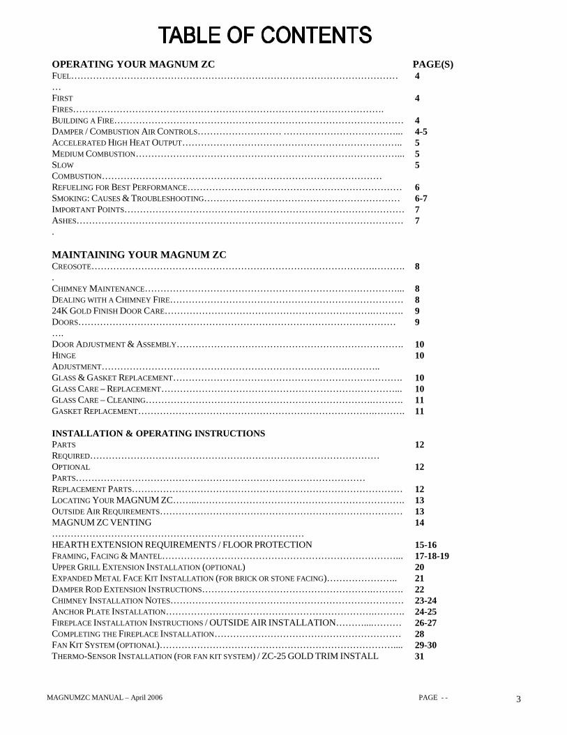
OPERATING YOUR MAGNUM ZC PAGE(S)FUEL………………………………………………………………………………………………
4
FIRSTFIRES……………………………………………………………………………………….
4
BUILDING A FIRE………………………………………………………………………………… 4DAMPER / COMBUSTION AIR CONTROLS……………………… ………………………………... 4-5ACCELERATED HIGH HEAT OUTPUT…………………………………………………………….. 5MEDIUM COMBUSTION…………………………………………………………………………... 5SLOWCOMBUSTION………………………………………………………………………………
5
REFUELING FOR BEST PERFORMANCE…………………………………………………………… 6SMOKING: CAUSES & TROUBLESHOOTING……………………………………………………… 6-7IMPORTANT POINTS……………………………………………………………………………… 7ASHES…………………………………………………………………………………………….
7
MAINTAINING YOUR MAGNUM ZCCREOSOTE……………………………………………………………………………….………..
8
CHIMNEY MAINTENANCE………………………………………………………………………... 8DEALING WITH A CHIMNEY FIRE………………………………………………………………… 824K GOLD FINISH DOOR CARE………………………………………………………….………. 9DOORS…………………………………………………………………………………………….
9
DOOR ADJUSTMENT & ASSEMBLY………………………………………………………………. 10HINGEADJUSTMENT…………………………………………………………………….………..
10
GLASS & GASKET REPLACEMENT……………………………………………………….………. 10GLASS CARE – REPLACEMENT…………………………………………………………………... 10GLASS CARE – CLEANING……………………………………………………………….………. 11GASKET REPLACEMENT………………………………………………………………….………. 11
INSTALLATION & OPERATING INSTRUCTIONSPARTSREQUIRED…………………………………………………………………………………
12
OPTIONALPARTS…………………………………………………………………………………
12
REPLACEMENT PARTS…………………………………………………………………………… 12LOCATING YOUR MAGNUM ZC……..…………………………………………………………. 13OUTSIDE AIR REQUIREMENTS…………………………………………………………………… 13MAGNUM ZC VENTING………………………………………………………………………
14
HEARTH EXTENSION REQUIREMENTS / FLOOR PROTECTION 15-16FRAMING, FACING & MANTEL…………………………………………………………………... 17-18-19UPPER GRILL EXTENSION INSTALLATION (OPTIONAL) 20EXPANDED METAL FACE KIT INSTALLATION (FOR BRICK OR STONE FACING)………………….. 21DAMPER ROD EXTENSION INSTRUCTIONS……………………………………………….………. 22CHIMNEY INSTALLATION NOTES………………………………………………………………… 23-24ANCHOR PLATE INSTALLATION………………………………………………………….………. 24-25FIREPLACE INSTALLATION INSTRUCTIONS / OUTSIDE AIR INSTALLATION………....……… 26-27COMPLETING THE FIREPLACE INSTALLATION…………………………………………………… 28FAN KIT SYSTEM (OPTIONAL)………………………………………………………………….... 29-30THERMO-SENSOR INSTALLATION (FOR FAN KIT SYSTEM) / ZC-25 GOLD TRIM INSTALL 31

MAGNUMZC MANUAL – April 2006 PAGE - - 4
APPENDIXSPECIFICATIONS…………………………………………………………………………………..
32
CLEARANCES TO COMBUSTIBLES………………………………………………………………... 32FIREBRICK & FIREBRICK BAFFLE LAYOUT…...………………………………………………… 33TROUBLE SHOOTING GUIDE……………………………………………………………………... 34-35WARRANTY INFORMATION………………………………………………………………………. 36-37
FUEL
The MAGNUM ZC is designed to work best when fueled with seasoned cordwood. Hardwoods arepreferred to softwoods since the energy content of wood is relative to its density. Hardwoods will result ina longer burning fire and less frequent refueling. The MAGNUM ZC should be fueled with wood cut to18” (457 mm) or less in length. Moisture content of 15% to 20%, wood seasoned for approximately two(2) years is preferred. Excessively wet wood will be difficult to burn, and will result in lower efficiency,increased creosoting, and deposits on the glass. Excessively dry wood will burn well but will also havehigher emissions and shorter burning time.
Do not burn scrap or garbage, treated wood, or wood such as driftwood from the ocean which has beenexposed to salt or other chemicals. Salt or chemicals can corrode the firebox and chimney. Do not abusethe unit by burning large amounts of paper or cardboard. Christmas tree branches or building constructionmaterials such as pressed wood, plywood, or lumber cannot be used. Intense firing with these mayoverheat the fireplace, causing damage to the unit or a chimney fire if the chimney is creosoted.
FIRST FIRES
Labels, which may have been applied to the glass, are easily removed before the fireplace is started.
The first 5 or 6 fires should be small fires of short duration (about 30-60 minutes). The first fire should beespecially short. This will help cure (dry) the refractory bricks and paint. The first fires may produce slightsmoking and smell due to curing of the paint and steel, and any dust accumulated on the fireplace will beburnt off at this time. For this reason the room should be well ventilated for the first few fires.
BUILDING A FIRE
To start a fire, place several crumpled up balls of newspaper in the firebox. Place small dry pieces ofkindling on top of the paper, crisscrossing the kindling so that there are air spaces in between. Place largerpieces of kindling on top of the pile. Open the damper and combustion air controls fully and light thenewspaper. Once the newspaper and kindling are well ignited cordwood can be added. The unit will burnbest with 2-4 pieces of cordwood spaced 1” (25mm) to 2” (50 mm) apart allowing air to get under thefuel. Crisscrossing, or arranging the fuel so that air can get underneath, will help the fire to get startedeasily. The unit should be operated with the damper and combustion air controls fully open long enough toget the cordwood well ignited. The airtight doors should be left open approximately 1” until the fire is wellestablished (usually 30-45 minutes). This will help keep the glass clean.
OPERATING YOUR MAGNUM ZC
MAGNUMZC MANUAL – April 2006 PAGE - - 5
DAMPER / COMBUSITON AIR CONTROLS
When starting a fire, open the damper and combustion air controls to the full open position (damper handlestraight up and ZC-60 combustion air knob pulled out). After the fire has had sufficient time to ignite,close damper control to desired setting, approximately 2/3 to fully closed) Normally the combustion aircontrol will be left fully open when the fire is burning, and closed when you are no longer using the unit. Ifyou have excessive chimney draft or want the unit to burn slower adjust the control up to ½ closed.NOTE: When you partially or fully close the combustion air-control you will get additional buildup ofsoot on the glass. When the unit is not in operation close the damper and the combustion air controls allthe way to minimize cold air penetration (frosting) of the unit glass when it is cold.
Always open the damper control fully open before opening the door, to minimize the possibility of backdrafting (smoke) coming into the room. Allow approximately 10 seconds of time before opening thedoors.
ACCELERATED COMBUSTION (High Heat Output)
The maximum heat output for the MAGNUM ZC is achieved by burning with the doors closed and thedamper and combustion air controls fully opened. By this method, the MAGNUM ZC can produce85,000+ BTU’s of heat per hour. It will be necessary to reload with wood every one to two hours. This isthe least efficient method of burning the MAGNUM ZC and must not be done for long periods of time.
Use caution when firing with the damper control wide open. Only burn hard cordwood in this manner.Never burn scrap wood or softwood in this manner. Damage to the firebox or chimney fires could occur.
Do not overfill with wood in an attempt to prolong reloading time. Too much wood may cause an overfire condition damaging the fireplace. Never load over 3-4 pieces of wood at a time on this setting.
MEDIUM COMBUSTION
This is the recommended way to operate your MAGNUM ZC to achieve the highest level of efficiencyand the least amount of creosote on the glass and in the chimney.
The damper control should be approximately 2/3 closed and the combustion air 2/3 to fully open. Theprecise setting will depend on many factors, including chimney height, house air tightness and the moisturecontent of the wood. Three (3) to four (4) medium size pieces of split wood (ranging from 4” to 8” indiameter should be burning on a bed of hot coals. The heat output will be approximately 65,000 BTU perhour and the loading time will be 3 to 4 hours. Softwoods may be burned using this method but burn timewill be substantially reduced.
SLOW COMBUSTION
Place four (4) to six (6) pieces of split wood six (6) inches or greater in diameter on top of a hot bed ofcoals. Close the damper control 2/3 to fully closed and adjust the combustion air control 2/3 closed. Thismethod of burning should be used only after operating the MAGNUM ZC with the damper control opento produce a hot fire (see Refueling For Best Performance). Creosote from the fire may accumulate on theglass doors unless the firebox is hot.

MAGNUMZC MANUAL – April 2006 PAGE - - 6
Slow combustion can be used at night in order to reduce the heat output and to prolong the burn.Although active burning will appear to cease after 4 to 6 hours, a bed of hot coals will continue to burn andproduce heat. These coals will remain hot throughout the night and will facilitate re-lighting the fire thenext morning.
This method of operation will accelerate creosote accumulation in the chimney. Therefore, it will benecessary to inspect and clean the chimney more frequently.
MAGNUMZC MANUAL – April 2006 PAGE - - 7
RE-FUELING FOR BEST PERFORMANCE
The MAGNUM ZC will operate best if attention is given to operating the unit with the damper open for ashort period of time after refueling in order to bring the fuel load as well as the fireplace/chimney system,up to its optimum operating temperature. By operating the MAGNUM ZC with a hot start afterrefueling, the MAGNUM ZC can achieve the burn rates of slow combustion, but with the temperature andperformance of medium combustion. Combustion efficiency is relative to firebox temperature, andtherefore ensuring that there is sufficient temperature in the firebox will improve performance. Once thefirebox is hot enough so that flames reach beyond the baffle, the damper can be closed to the minimumsetting. If the flames do not continue beyond the edge of the baffle, the air control should be reopened toestablish a hotter fire. The benefit of this technique will be cleaner glass, less creosoting, greater efficiency,and the most pleasing fire for your enjoyment.
SMOKING: Causes and troubleshooting
To reduce the likelihood of smoking when opening the doors, open the damper before opening the doors.Your fireplace has been designed and tested to provide smoke free operation. Occasionally there may be asmall amount of smoking upon lighting the fire, until the chimney heats up, but this should not continue. Ifthe fireplace continues to smoke it is probably due to one or more of the following reasons:
1. THE DOORS ARE PARTIALLY OPENü Open both doors fully when opening them.
2. NOT ENOUGH REPLACEMENT AIR (HOUSE DEPRESSURIZATION)ü As the fire burns, air goes up the chimney. This air must be replaced through leakage into the house, or
through the outside air duct (if installed). When operating the MAGNUM ZC, the outside air supplyshould be open. Open a nearby window temporarily to check the adequacy of the replacement airsupply. Correct depressurization problem by installing make-up air.
3. VENTILATOR FAN OPERATING (HOUSE DEPRESSURIZATION)ü These fans draw air out of the house and may actually draw air down the chimney. Open a nearby
window and turn off all fans to determine if this is the cause of the problem.
4. TOO LARGE OF A FIREü Do not burn more than 3”-4” medium (4” diameter) (100 mm) size logs at a time.
5. WET WOODü Wet or tarred wood will smolder and smoke instead of burn properly.
6. DIRTY OR BLOCKED CHIMNEYü Check to make sure the chimney is clear and reasonably clean.
7. CHIMNEY HEIGHT NOT SUFFICIENTü The chimney must extend at least 3’ (915 mm) above its point of contact with the roof and at least 2’
(610 mm) higher than any roof or wall within 10’ (3 m) of it. When installed with offsets, additionalheight is required to maintain the minimum height and to compensate for the decrease in draft.Additional height will increase draft and will decrease the tendency to smoke if caused by low draft. Tallbuildings, trees, and surrounding hills will cause down drafts resulting in back drafting (smoking) whenopening the fireplace doors.
MAGNUMZC MANUAL – April 2006 PAGE - - 8
8. NEGATIVE PRESSURE IN THE HOUSEü With no fire, there should be sufficient draft to exhaust cigarette smoke or other smoke introduced under
the baffle. If the chimney has been installed properly and is operating properly, then the smoke shouldgo up the flue. Chimneys that have an installation deficiency, or one or more of the above problems,may be drawing cold air down the flue and into the room. These chimneys will often smoke temporarilyon startup until the chimney is heated up. Closing upstairs windows and opening a nearby window willhelp to overcome smoking caused by house depressurization.
IMPORTANT POINTS:
• Use Solid Fuel Only
ü Do not block the hot air vents or air inlet to the fireplace, as this will cause the fireplace to overheat.ü Never start a fire using gasoline, kerosene, charcoal lighter fluid, or any other combustible liquid.ü Do not burn coal. The sulfur in coal will corrode the firebox.ü Do not burn driftwood that has been in the ocean or salt water. The salt will corrode the firebox and
chimney.ü Do not operate the unit with the doors partially open (except on startup), or with one door open, since
this may cause smoke to be drawn into the room. (Doors must be fully open or fully closed.)ü Do not burn wood in the area in front of the log guard or a log grate (if used).ü Do not abuse the unit by over firing or by burning paper, cardboard or construction material such as
pressed wood, plywood, or lumber.ü Do not allow the wood to smolder or burn without flame, since this will produce excessive creosote
and cause the glass to become dirty.ü Warning: Never use substitute glass materials. If the glass needs replacement, order glass #AR-1400
from your MAGNUM ZC dealer.ü Warning: Do not slam doors shut – Do not hit doors with logs, this can cause serious damage to
doors and/or break the high temperature glass.ü Keep small children away from fireplace. Front surfaces are extremely hot.ü Warning: Do not clean door glass while hot. Wait for unit to cool down before servicing or cleaning.
ASHES
Remove ashes only when the fire is out and the ashes are cold. Place the ashes in a metal container with atight fitting lid. Do not put ashes in a cardboard box, and do not place the container on or nearcombustible material. The ashes remain hot for days and can start a fire. Do not leave the ashes in thehouse as they give off carbon monoxide and other toxic gases.
Stirring the ashes in the firebox occasionally when loading wood will cause them to burn thoroughly andreduce the need for removing the ashes.

MAGNUMZC MANUAL – April 2006 PAGE - - 9
CREOSOTE
When wood is burned slowly, it produces tar and other organic vapors, which combine with expelledmoisture to form a black deposit, called creosote. The creosote vapors condense in the relatively coolchimney flue of a slow-burning fire. As a result, creosote residue accumulates on the flue lining. Whenignited, this creosote makes an extremely hot fire. If the creosote accumulation is large, a creosote fire inthe chimney can damage the chimney and overheat the surrounding wood framing. Creosote formation ina chimney can be minimized by making small hot fires rather than slow burning, smoldering fires, and byproper refueling techniques. The MAGNUM ZC is designed and tested to produce a low amount ofemissions when operated correctly.
CHIMNEY MAINTENANCE
Regular chimney inspections and maintenance combined with proper operation will prevent chimney fires.Keep your chimney clean. Do not allow more than 1/16” creosote buildup in your chimney. The amountof creosote will depend on variables such as frequency of use and type of fire. We recommend that you:
ü Initially inspect the chimney system every month or two. From this you will learn how often it will benecessary to clean your chimney.
ü Have your chimney cleaned by a qualified chimney sweep. If you wish to clean it yourself, werecommend using a stiff plastic or non-metallic brush. If a metal brush is used, its size should beslightly smaller than the flue to avoid damaging the chimney. Do not use a brush that will scratch thestainless steel interior of the chimney. Do not expect chemical cleaners to keep your chimney clean.
ü The rain cap can be removed for inspection and/or cleaning of the chimney.
DEALING WITH A CHIMNEY FIRE
Regular chimney maintenance and inspection combined with proper operation can prevent chimney fires.
If you have a chimney fire, follow these steps:
1) Close the fireplace doors and damper / combustion air dampers.2) Alert your family of the possible danger.3) Alert your fire department.4) If possible, use a dry chemical fire extinguisher, baking soda or sand to control the fire. Do not use
water as it may cause a dangerous steam explosion.5) Check outside to ensure that sparks and hot embers coming out of the chimney are not igniting the
roof.6) Do not use the fireplace again until your chimney and fireplace has been inspected by a qualified
chimney sweep or a Fire Department Inspector.
MAINTAINING YOUR MAGNUM ZC

MAGNUMZC MANUAL – April 2006 PAGE - - 10
24K GOLD FINISH DOOR CARE (optional)
Use a soap and water mixture and a soft cloth to clean the 24K gold surface. Do not use abrasives such assteel wool or steel pads for they will scratch the gold finish. Do not use harsh polishing agents as they willwear off the gold surface.
DOORS (It is not recommended to interchange doors once they are installed on your unit)
The doors come mounted and adjusted on the MAGNUM ZC fireplace. If you are changing to a differentfinish option there may have to be adjustments made to the door hinges and latches.
Keep the door latches and hinges lubricated with all-purpose grease such as WD-40, at least once a year.To adjust the tightness of the door latch follow the instructions listed below. If the doors are out ofalignment, you will have to take the doors off of the hinges and tap the hinges in or out to align the doorsstraight with each other. Be sure to place the door pin in the hinge hole before tapping on the hinge tokeep the hole from becoming out of round.
FIREPLACE DOOR INSTALLATION INSTRUCTIONS
PARTS LIST
1) Spring Handles R-1162) Steel Shank 1273) Steel Collar 2X-5684) Spring 36100G5) Expand Pin 146) Steel Shank 1267) Set Screw 14208) Allen Wrench 1/8”
FIGURE 2Left Door Handle Breakdown
FIGURE 3Right Door Handle Breakdown
FIGURE 1
COMPLETE DOOR ASSEMBLY
1) Black Doors ACI-B-A2) 24 Karat Gold Doors ACI-24K-A3) Nickel Doors ACI-NKL-A
Only these door assemblies can be usedon the Magnum ZC fireplace.
èí
å å
ç
é é
êë
MAGNUMZC MANUAL – April 2006 PAGE - - 11
RIGHT HANDLE ASSEMBLY: Place the #3 steel collar over the #2 steel shank and place the steelshank through the ½” hole located on the bottom of the right door. Then place the #4 spring over the ½”shaft sliding it against the cast iron door. Then while supporting the steel shank underneath with a hammeror such, install the #5 expand pin. Note that the #5 expand pin must be installed with the pin facing so thatwhen the door is closed the spring handle will be facing to the right. SEE THE ASSEMBLY IN FIGURE1 & 3. To adjust the right door, simply pull on the steel shank to give it a little spring tension and thentighten the set screw on the steel collar using the #9 Allen wrench provided. Adjust the door so that thehandle pulls the door up so that the gasket seals against the doorframe. DO NOT OVER TIGHTEN THEDOOR AS IT WILL TWIST THE CAST FRAME AND COULD CAUSE GLASS BREAKAGE.
LEFT HANDLE ASSEMBLY: Place the #3 steel collar over the #6 steel shank and place in the ½” holelocated on the bottom of the right door. Next, place the #7 set screw in the threaded hole directly belowthe handle and turn into place. Align the #6 steel shank so that it is at the same angle as the left handle,facing left. Then tighten the setscrew with the #9 Allen wrenches provided. Finally, slide the #3 steelcollar up against the cast and tighten. (SEE FIGURE 2)
NOTE: The spring handles are installed by twisting them onto the ½” steel shank like you would screw ona nut. Apply a slight amount of pressure as you turn the spring handles into place.
GLASS & GASKET REPLACEMENT
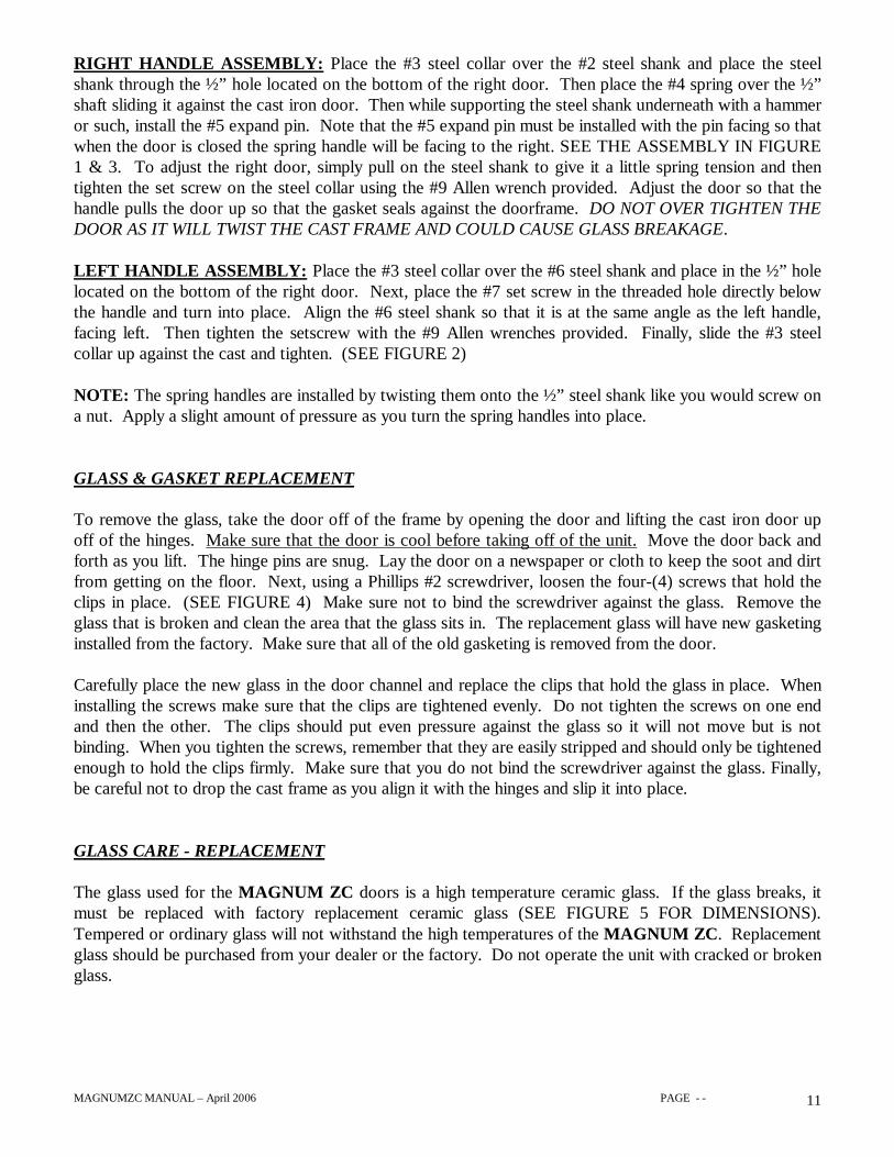
To remove the glass, take the door off of the frame by opening the door and lifting the cast iron door upoff of the hinges. Make sure that the door is cool before taking off of the unit. Move the door back andforth as you lift. The hinge pins are snug. Lay the door on a newspaper or cloth to keep the soot and dirtfrom getting on the floor. Next, using a Phillips #2 screwdriver, loosen the four-(4) screws that hold theclips in place. (SEE FIGURE 4) Make sure not to bind the screwdriver against the glass. Remove theglass that is broken and clean the area that the glass sits in. The replacement glass will have new gasketinginstalled from the factory. Make sure that all of the old gasketing is removed from the door.
Carefully place the new glass in the door channel and replace the clips that hold the glass in place. Wheninstalling the screws make sure that the clips are tightened evenly. Do not tighten the screws on one endand then the other. The clips should put even pressure against the glass so it will not move but is notbinding. When you tighten the screws, remember that they are easily stripped and should only be tightenedenough to hold the clips firmly. Make sure that you do not bind the screwdriver against the glass. Finally,be careful not to drop the cast frame as you align it with the hinges and slip it into place.
GLASS CARE - REPLACEMENT
The glass used for the MAGNUM ZC doors is a high temperature ceramic glass. If the glass breaks, itmust be replaced with factory replacement ceramic glass (SEE FIGURE 5 FOR DIMENSIONS).Tempered or ordinary glass will not withstand the high temperatures of the MAGNUM ZC. Replacementglass should be purchased from your dealer or the factory. Do not operate the unit with cracked or brokenglass.
MAGNUMZC MANUAL – April 2006 PAGE - - 12
GLASS CARE CLEANING
The MAGNUM ZC has an air wash system designed to keep the glass fairly clean under normalconditions. A small amount of soot may build up on the glass area, especially if the doors are not sealedtightly (see door adjustments). Under low fire conditions (combustion damper closed) the glass will tendto get dirty unless the fuel, firebox and glass are maintained at hot temperatures (see refueling).
To clean the glass, there are a number of specially designed cleaners. Your authorized MAGNUM ZCDealer can recommend a suitable cleaner which is available in your area. Regular household glass cleanerswill not clean creosote. Do not use abrasives such as steel pads, steel wool or oven cleaner as they willscratch the glass. TIP: Amway® brand cream glass cleaner works great.
GASKET REPLACEMENT
Remove the doors from the unit and lay them gasket side up on a clean soft surface. To replace the gasket,first remove the entire old gasket and gasket cement. Make sure that the surface is totally clean beforeapplying new cement or adhesion problems may result. Apply gasket cement to the gasket channel (app.1/8” bead), and install the new gasket, available from your MAGNUM ZC Dealer.
Gasket lengths are:n Gasket around glass (R-105) 52 long Qty: 2 1/8” x ¾” window gasketn Gasket on door frame (R-106) 48 long Qty: 2 3/8” med. density graphite coated rope
13 ¾”
10 ½”
FIGURE 5
16 ¼”
FIGURE 4
CLIP (4)
GASKET COMESINSTALLED ON GLASS
10-24 SCREW

MAGNUMZC MANUAL – April 2006 PAGE - - 13
Read these instructions and keep them for future reference. Before installing your fireplace, consult yourlocal building authority to obtain a building permit as well as information on the specific requirements inyour area. Install the fireplace only as described in these instructions and using only approved components.The MAGNUM ZC is not intended for use with a gas log other than the factory supplied SP-40-ZC gasretrofit system. Failure to follow these instructions will void the certification and the warranty of thefireplace, and may result in an unsafe installation.
NOTE: The MAGNUM ZC can only be installed with 8” or 7” diameter listed type 2100’ HT insulatedor air- cooled chimney. It is strongly recommended to use 8” diameter chimney whenever possible.If you are not using our UGA-B-32-ZC upper grill you must have a minimum of 125 square inchesof open area to allow the heat to exit the unit. If you are using remote ducting you must have aminimum of 100 square inches of open area in the front heat outlet of the unit.
The MAGNUM ZC is not tested for use with a masonry chimney or with a chimney liner.
REPLACEMENT PARTS:
ü R-102 -Arched Ceramic 1400 Degree Replacement Glass (Specify left or right)ü R-105 (per door) -Thermo-Tape Gasketing for glass sealü R-106 (per door) -Thermo-Cord Gasketing for door seal (includes gasket cement)ü R-116 - Spring Door Handles (each door)ü R-120 -Right Handle Kit (Steel)ü R-121 -Left Handle Kit (Steel)ü R-145 -Glass hold down clip (each)ü R-146 -Glass hold down clip screw (each)
Listed: Warnock Hersey February 1994 Test DateStandards: UL 127 - UL 1482 - ULC S627 - ULC S610
INSTALLATION AND OPERATING INSTRUCTIONS
PARTS REQUIRED:
ü Fireplace Model MAGNUM ZCü 8” or 7” diameter listed 2100 degree type HT
insulated or air-cooled chimney systemü Anchor plate (supplied with chimney system)ü 4” outside combustion air hookup (supplied by
dealer)ü ZC-65 (8” to 7”) chimney adapter if using 7”
chimney system
OPTIONAL ACCESSORIES:
ü Fan Kitü Brass grillsü Brass Trim Kitsü Arched Lintel Iron

MAGNUMZC MANUAL – April 2006 PAGE - - 14
ü The best location for your fireplace is determined by considering the location of windows, doors, andthe traffic flow in the room where the fireplace is located, allowing space in front of the unit for thehearth extension and the mantel, and taking into consideration the location of the hot air ducts, outsideair kit (if so equipped), and chimney. If possible, you should choose a location where the chimney willpass through the house envelope (interior walls).
ü Usually no additional floor support is needed for the fireplace. The adequacy of the floor can bechecked by first estimating the weight of the fireplace system. Weights are given in the appendix.Next, measure the area occupied by the system. This will normally be 42” X 23” (1067 X 584 mm) forthe fireplace. Note the floor construction as to the sizes and type of flooring and joists, and thenconsult your local building code to determine if additional support is needed. It is your responsibility todetermine the weight load for additional facing materials such as brick or rock.
ü The MAGNUM ZC can be installed above the floor level on a base, (see Hearth ExtensionRequirements) provided that there is a minimum of 7’ (2135 mm) measured from floor to the ceiling.This allows adequate room for venting and ductwork.
ü If you are installing the fireplace on an exterior wall, the wall must be insulated the same as the otherwalls in the home. If this is not done there will be excessive cold air transfer into the home.
OUTSIDE AIR REQUIREMENTS
During operation, the fireplace requires air for combustion and will draw air out of the house. It maystarve other fuel burning appliances such as gas or oil furnaces. As well, exhaust fans and fan drivenappliances may compete for air, causing a negative pressure in the house and resulting in smoke enteringthe home from the appliance. This situation is aggravated in modern airtight houses. To overcome thispotential problem, you must install an Outside Air Kit with the MAGNUM ZC. The kit is mandatory inmost areas. Check with your local building authority for requirements in your area. The outside air kitmust be installed according to the following guidelines:
ü The maximum length of duct is 25’ (6.1 m). Duct length should be kept to a minimum. If duct length is over 10’increase the size to 6”. Do not have over 3 elbows.
ü The air intake vent must not be installed more than 7’ (2135 mm) above the base of the appliance.
ü The fresh air must come from outside the house. It must not draw air from the attic or basement.
ü Locate the outside vent where it will be well away from automobile exhaust fumes, gas meters, or other vents.
ü The air intake vent should be installed where it is not likely to be blocked by snow or exposed to extreme wind.
ü The duct and vent may be installed above or below floor level.
ü Use only factory approved MAGNUM ZC components.
ü Cannot terminate in an attic or crawl space.
Secure all connections with screws to prevent them from coming apart and leaking cold air. All piping should be insulated.
LOCATING YOUR MAGNUM ZC

MAGNUMZC MANUAL – April 2006 PAGE - - 15
MAGNUM ZC VENTINGFOR OPENINGS ON TOP OF UNIT
11.875
21.00
20.50
41.00
8” Dia. Chimney Outlet
Front of unit

MAGNUMZC MANUAL – April 2006 PAGE - - 16
HEARTH EXTENSION REQUIREMENTS
The MAGNUM ZC can be installed directly on a combustible or wood floor but we strongly recommendplacing a 3/8” thick rock board underneath the unit for added protection. HOWEVER, the floor of thehearth extension (the area in front of the unit) must be protected from sparks and heat by a non-combustible hearth extension. The minimum size of the protected area is 40”wide X 18”deep (1016 X 458mm) extending in front of the loading door (SEE FIGURE 6). The MAGNUM ZC is certified for usewith either of the following installations:
ü When installing the MAGNUM ZC and the hearth extension directly on a combustible floor, it isREQUIRED that the hearth extension have an R value of 2.2 (3/8” rock board or mineral wool board)
OR
ü If installing on a raised base or raised hearth, a “z” shaped piece of metal is used to join the undersideof the fireplace to the hearth extension (SEE FIGURE 7).
ü Always install the hearth extension at least ¾” under the MAGNUM ZC fireplace.
ü If hearth extension is equal or greater than 8” high and equal or greater than 16” deep, area in frontdoes not need protection.
40”
FIGURE 7
1”17”
18”HEARTH PROTECTION
40”
8” MINIMUM
HEAT DUCT GRILLS FOR ZC-50
MAGNUMZC MANUAL – April 2006 PAGE - - 17
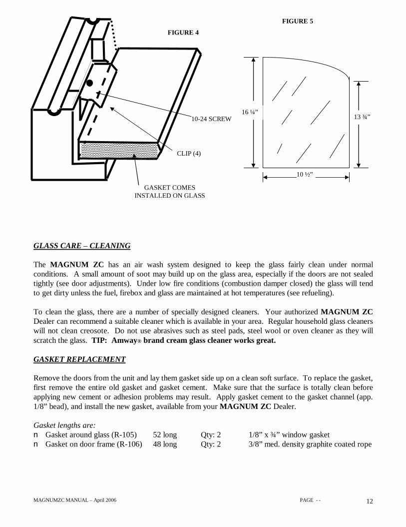
HOW TO DETERMINE IF FLOOR PROTECTION MATERIALS ARE ACCEPTABLE
ü All floor protection materials must be non-combustible (i.e., metals, brick, stone, mineral fiberboard,etc.). Any organic materials (i.e., plastics, wood, paper products, etc.) are combustible and must notbe used.
ü The floor protector specified may include some form of thermal designation such as R-value (thermalresistance), or K-factor (thermal conductivity), or C-factor (thermal conductance). 3/8” thick rockboard or mineral wool board meets these specifications.
The technical means of determining if a proposed alternate floor protector meets requirements listed in theappliance manual is to follow this procedure:
a) Convert specification to R-value:• R-value given – no conversion needed.• K-value is given with a required thickness
(T) in inches:R = 1/K X T (1)
• C-value is given:R = 1/C (2)
b) Determine the R-value of the proposed alternate floor protector.• Use the formula in step (a) to convert values not expressed as “R.”• For multiple layers, add R-values of each layer to determine overall R-value.
c) If the overall R-value of the system is greater than the R-value of the specified floor protector, thealternate is acceptable.
EXAMPLE:The specified floor protector should be ¾ inch thick material with a K-value of .84. The proposedalternate is 4” brick with a C-value of 1.25 over 1/8” mineral board with a K-value of .29.
Step (a): Use formula (1) to convert specification to R-value. R + 1/K X T + 1/.84 X .75 + .893
Step (b): Calculate R of proposed system. 4” brick of C = 1.25 Rbrick = 1/C = 1/1.25 = .80
1/8’ mineral board of K = .29 Rmin.bd. = 1/.29 X .125 - .431
Total R = Rbrick + Rmineral board = .8 + .431 = 1.231
Step (c): Compare proposed system of R of 1.231 to specified R of .893. Since proposed system Ris greater than required, the system is acceptable.
Simply put, 3/8” thick rock board or mineral wool board will meet these specifications.
Thermal Conductance = C = Btu(hr) (ft2) (F)
Thermal Conductivity = k = (Btu) (in) (hr) (ft2) (F)
or Btu
(hr) (ft) (F)
Thermal Resistance = R = (ft2) (hr) (F) Btu

MAGNUMZC MANUAL – April 2006 PAGE - - 18
The construction of the framing, facing, and mantel must be in accordance with these guidelines andillustrations.
FRAMING
ü Frame the fireplace using 2” X 3” (50 X 75 mm) or heavier lumber.
ü WARNING: Combustible material cannot be placed behind the top standoffs of the fireplace. Thisarea must remain empty for a height of 7’ (2135 mm) measured from the base of the appliance. Framethe fireplace with vertical studs at the sides of the fireplace running from floor to ceiling (SEE FIGURE8). The enclosure can be framed prior to installation, allowing 42”(1067 mm) wide and 23” (584 mm)deep (SEE FIGURE 8). If combustible facing is to be used, position the studs back from the frontedge of the fireplace and space the thickness of the facing material in order that the facing can beinstalled flush with the fireplace facing. Combustible materials must not touch the unit.
ü Frame headers between the vertical studs only as follows:
ü Place 2” X 3” (50 X 75 mm) or 2” X 4” (50 X 100 mm) headers (SEE FIGURE 8) between the studsonly along the upper part of the front, side and back faces. Do not put wood or any combustiblematerial within the area behind the standoffs on top of the unit. This area is for venting and ductwork.
ü Place headers only as required to support the facing and mantel, and place all headers on edge.
A B C D E FINCHES 41 83 41 1/2 59 26 22
MILLIMETERS
1025 2075 1037.5 1475 650 550
FRAMING, FACING AND MANTEL
A
B
CD
E
F
FIGURE 9 FIGURE 10

MAGNUMZC MANUAL – April 2006 PAGE - - 19
FRAMING, FACING & MANTEL, CON T
36”
22”
41”
7’ 49” 47”37½”
2”x3” or 2”x4”FIGURE 8

MAGNUMZC MANUAL – April 2006 PAGE - - 20
FACING
ü Combustible material must be installed flush with the fireplace. It may not project in front of and onthe fireplace (i.e. the steel faceplate of the MAGNUM ZC) (SEE FIGURE 11).
ü Non-combustible materials such as brick, stone or ceramic tile may project in front of and onto thefireplace facing as long as proper facing attaching materials are used (SEE FIGURE 12).
ü Do not block the upper grill at the fireplace front with facing material.
MANTEL
The mantel must be installed at least 58” (1450 mm) (no ducting) or 53” (1325mm) (both ducts) above thebase of the fireplace and at least 6” (152 mm) away from any hot air outlet framing.
FIGURE 11 FIGURE 12
53” or 58”reference
above
MAGNUMZC MANUAL – April 2006 PAGE - - 21
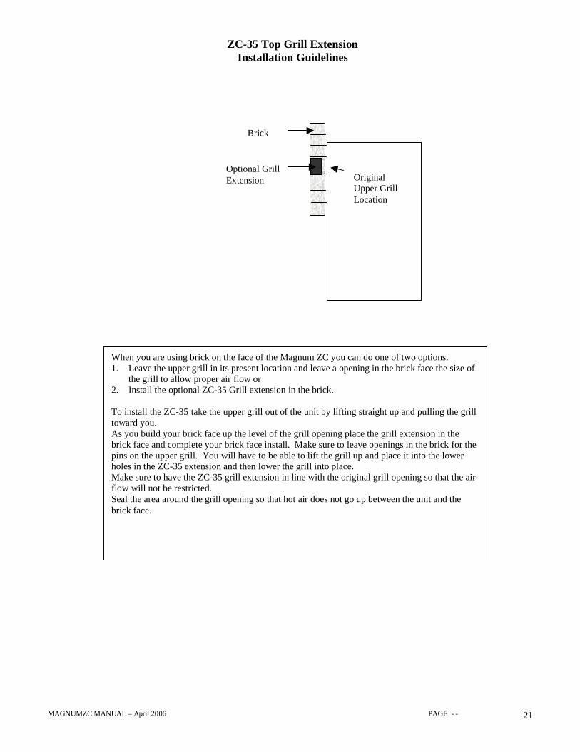
ZC-35 Top Grill ExtensionInstallation Guidelines
Brick
Optional GrillExtension Original
Upper GrillLocation
When you are using brick on the face of the Magnum ZC you can do one of two options.1. Leave the upper grill in its present location and leave a opening in the brick face the size of
the grill to allow proper air flow or2. Install the optional ZC-35 Grill extension in the brick.
To install the ZC-35 take the upper grill out of the unit by lifting straight up and pulling the grilltoward you.As you build your brick face up the level of the grill opening place the grill extension in thebrick face and complete your brick face install. Make sure to leave openings in the brick for thepins on the upper grill. You will have to be able to lift the grill up and place it into the lowerholes in the ZC-35 extension and then lower the grill into place.Make sure to have the ZC-35 grill extension in line with the original grill opening so that the air-flow will not be restricted.Seal the area around the grill opening so that hot air does not go up between the unit and thebrick face.

MAGNUMZC MANUAL – April 2006 PAGE - - 22
EXPANDED METAL FACE KIT INSTALLATION(FOR STONE, BRICK & TILE FACING) Mesh Kit (ZC-75)
1) Take the mesh kit and hardware out of the packaging and make sure that all items are included. Contact yoursupplier if any parts are missing.
2) Align the left & right panels so that the mesh openings are facing upwards and the angle iron is close to the frontface plate of the unit. Do not butt the angle iron tight against the face plate. Leave a small amount of expansionroom (1/16” is normal).
3) Fasten the mesh in place using the self drilling and tapping screws provided. Screws every 8-10 inches apart issufficient. Do not tighten the screws tight on the face of the unit. Leave expansion room for the mesh to move(1/32” is sufficient).
4) Either wood screws or nails (not provided) can be used to fasten the mesh to the wood studs on the left and rightsides of the unit (these should be tight).
5) Follow the same procedure for the top panel.
6) Make sure that the grill opening is aligned parralel and straight with the unit.
WARNING: Wear gloves when handling / installing the Mesh Kit. The edges are sharp !!
FIGURE 13
TopPanel
Front Face Plate of Unit
Lower Grill
WoodStuds
DamperHandle
UpperGrill
Left SidePanel
Angle Ironframetoward
flange ofunit
Mesh facingupward
Outline ofsides and top
of unitbehind ZC-
Right SidePanel
Angle Ironframetoward
flange ofunit
Mesh facingupward
Tools needed:
ü Hand Drill
ü ¼” Nut Driver
ü (optional)Hammer and 16penny nails
ZC-75 Mesh KitIncludes:
ü Top Panel
ü Left Panel
ü Right Panel
(36) # 8 tek screws
Overall width 44.250 in.
Overall Ht.48.500 in.
MAGNUMZC MANUAL – April 2006 PAGE - - 23
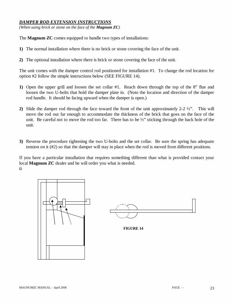
DAMPER ROD EXTENSION INSTRUCTIONS(When using brick or stone on the face of the Magnum ZC)
The Magnum ZC comes equipped to handle two types of installations:
1) The normal installation where there is no brick or stone covering the face of the unit.
2) The optional installation where there is brick or stone covering the face of the unit.
The unit comes with the damper control rod positioned for installation #1. To change the rod location foroption #2 follow the simple instructions below (SEE FIGURE 14).
1) Open the upper grill and loosen the set collar #1. Reach down through the top of the 8” flue andloosen the two U-bolts that hold the damper plate in. (Note the location and direction of the damperrod handle. It should be facing upward when the damper is open.)
2) Slide the damper rod through the face toward the front of the unit approximately 2-2 ½”. This willmove the rod out far enough to accommodate the thickness of the brick that goes on the face of theunit. Be careful not to move the rod too far. There has to be ½” sticking through the back hole of theunit.
3) Reverse the procedure tightening the two U-bolts and the set collar. Be sure the spring has adequatetension on it (#2) so that the damper will stay in place when the rod is moved from different positions.
If you have a particular installation that requires something different than what is provided contact yourlocal Magnum ZC dealer and he will order you what is needed.ü
éçå FIGURE 14

MAGNUMZC MANUAL – April 2006 PAGE - - 24
GENERAL NOTES
ü If possible install an interior chimney as it will provide better performance. In areas with continuoustemperatures below 18 C (0 F), the use of an exterior chimney increases the likelihood of operatingproblems such as low draft, high rate of creosoting, and poor startup characteristics. Exteriorchimneys are also prone to down drafting and flow reversal. Installations which are located low in thehouse such as in a basement, in combination with outside chimneys, are especially prone to flowreversal.
ü A chimney venting a fireplace shall not vent any other appliance.
ü The MAGNUM ZC fireplace is not listed for use with a masonry chimney or with chimney liner.
ü The minimum chimney height, including fireplace, is 12’ 6” (3.8 m) for vertical chimney.
ü Chimney – Any listed type HT 7” or 8” diameter 2100 degree insulated or air-cooled.
ü The maximum chimney height supported by the fireplace is 10’ (3 m). If additional height is required,use a roof support at 30’ (9 m) interval.
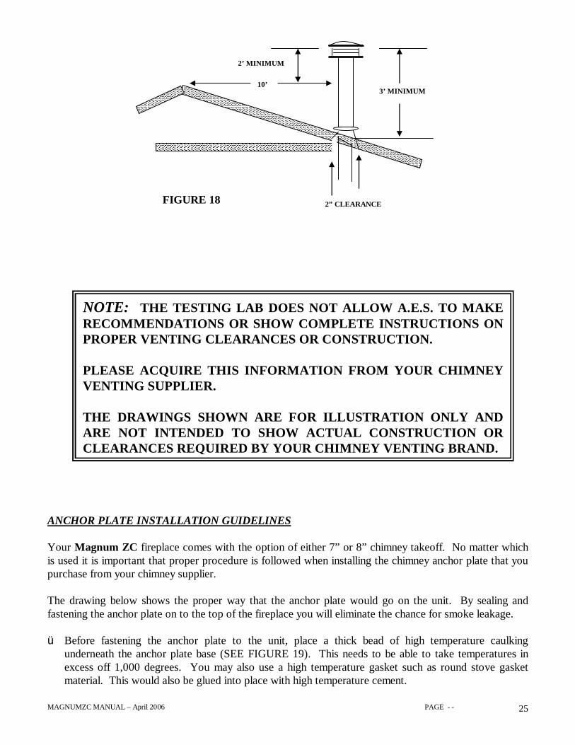
ü The chimney must extend at least 3’ (915 mm) above its point of contact with the roof and at least 2’(610 mm) higher than any wall, roof or building within 10’ (3000 mm) of it (SEE FIGURE 18).
ü If the chimney extends higher than 5’ (1500 mm) above the roof, it must be secured using a roof braceor guide wires.
ü A rain cap must be installed on top of the chimney. Failure to install a rain cap may cause the fireplaceto corrode. The warranty will be void if a rain cap is not used.
ü Cut and frame square holes in all floors and the roof to provide 2” (50 mm) of clearance between thechimney and any combustible material. Do not fill this 2” (50 mm) space with any material.
ü Portions of the chimney may extend through accessible spaces and shall be enclosed in all cases toavoid personal contact with the chimney and damage to the chimney.
CHIMNEY INSTALLATION NOTES
MAGNUMZC MANUAL – April 2006 PAGE - - 25
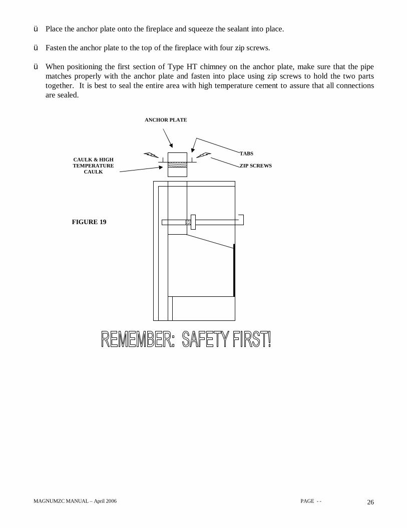
ANCHOR PLATE INSTALLATION GUIDELINES
Your Magnum ZC fireplace comes with the option of either 7” or 8” chimney takeoff. No matter whichis used it is important that proper procedure is followed when installing the chimney anchor plate that youpurchase from your chimney supplier.
The drawing below shows the proper way that the anchor plate would go on the unit. By sealing andfastening the anchor plate on to the top of the fireplace you will eliminate the chance for smoke leakage.
ü Before fastening the anchor plate to the unit, place a thick bead of high temperature caulkingunderneath the anchor plate base (SEE FIGURE 19). This needs to be able to take temperatures inexcess off 1,000 degrees. You may also use a high temperature gasket such as round stove gasketmaterial. This would also be glued into place with high temperature cement.
3’ MINIMUM10’
2’ MINIMUM
FIGURE 18 2” CLEARANCE
NOTE: THE TESTING LAB DOES NOT ALLOW A.E.S. TO MAKERECOMMENDATIONS OR SHOW COMPLETE INSTRUCTIONS ONPROPER VENTING CLEARANCES OR CONSTRUCTION.
PLEASE ACQUIRE THIS INFORMATION FROM YOUR CHIMNEYVENTING SUPPLIER.
THE DRAWINGS SHOWN ARE FOR ILLUSTRATION ONLY ANDARE NOT INTENDED TO SHOW ACTUAL CONSTRUCTION ORCLEARANCES REQUIRED BY YOUR CHIMNEY VENTING BRAND.
MAGNUMZC MANUAL – April 2006 PAGE - - 26
ü Place the anchor plate onto the fireplace and squeeze the sealant into place.
ü Fasten the anchor plate to the top of the fireplace with four zip screws.
ü When positioning the first section of Type HT chimney on the anchor plate, make sure that the pipematches properly with the anchor plate and fasten into place using zip screws to hold the two partstogether. It is best to seal the entire area with high temperature cement to assure that all connectionsare sealed.
TABS
ZIP SCREWSCAULK & HIGHTEMPERATURE
CAULK
ANCHOR PLATE
FIGURE 19

MAGNUMZC MANUAL – April 2006 PAGE - - 27
DO NOT PLACE INSULATION OR ANY OTHER MATERIAL IN THE AIR SPACE AROUNDTHE CHIMNEY OR FIREPLACE. INSULATION PLACED ON OR AROUND THE FIREPLACE
OR CHIMNEY MAY CAUSE ADJACENT WOOD TO OVERHEAT AND CATCH ON FIRE.
FIGURE 20
RAIN CAP
STORM COLLAR
ROOF FLASHING
ATTIC RADIATIONSHIELD
OUTSIDE FRESH AIR DUCT
HEARTH
58” minimum w/oduct53” minimum w/ duct
WOOD MANTLE
8” minimumCEILING

MAGNUMZC MANUAL – April 2006 PAGE - - 28
INSULATED CHASE CONSTRUCTION
FIGURE 21
Air VaporBarrier
Insulation
MAGNUMZC MANUAL – April 2006 PAGE - - 29
1) Move the fireplace into place.
2) Install the outside air assembly.
3) Install the floor protector. Refer to the section Hearth Extension Requirements and make sure the gapbetween the fireplace and the hearth extension is sealed (refer to page 15).
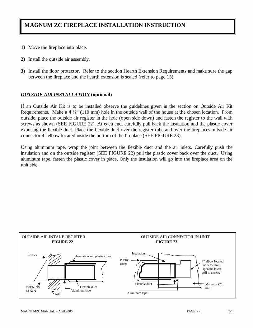
OUTSIDE AIR INSTALLATION (optional)
If an Outside Air Kit is to be installed observe the guidelines given in the section on Outside Air KitRequirements. Make a 4 ¼” (110 mm) hole in the outside wall of the house at the chosen location. Fromoutside, place the outside air register in the hole (open side down) and fasten the register to the wall withscrews as shown (SEE FIGURE 22). At each end, carefully pull back the insulation and the plastic coverexposing the flexible duct. Place the flexible duct over the register tube and over the fireplaces outside airconnector 4” elbow located inside the bottom of the fireplace (SEE FIGURE 23).
Using aluminum tape, wrap the joint between the flexible duct and the air inlets. Carefully push theinsulation and on the outside register (SEE FIGURE 22) pull the plastic cover back over the duct. Usingaluminum tape, fasten the plastic cover in place. Only the insulation will go into the fireplace area on theunit side.
MAGNUM ZC FIREPLACE INSTALLATION INSTRUCTION
OUTSIDE AIR INTAKE REGISTER OUTSIDE AIR CONNECTOR IN UNITFIGURE 22 FIGURE 23
OPENINGDOWN
wallAluminum tape
Flexible duct
Insulation and plastic cover
Aluminum tape
Flexible duct
4” elbow locatedunder the unit.Open the lowergrill to access.
Plasticcover
Insulation
Magnum ZCunit.
Screws
MAGNUMZC MANUAL – April 2006 PAGE - - 30
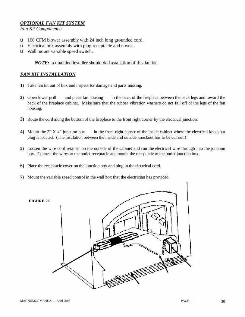
OPTIONAL FAN KIT SYSTEMFan Kit Components:
ü 160 CFM blower assembly with 24 inch long grounded cord.ü Electrical box assembly with plug receptacle and cover.ü Wall mount variable speed switch.
NOTE: a qualified installer should do Installation of this fan kit.
FAN KIT INSTALLATION
1) Take fan kit out of box and inspect for damage and parts missing.
2) Open lower grillç and place fan housingå in the back of the fireplace between the back legs and toward theback of the fireplace cabinet. Make sure that the rubber vibration washers do not fall off of the legs of the fanhousing.
3) Route the cord along the bottom of the fireplace to the front right corner by the electrical junction.
4) Mount the 2” X 4” junction boxè in the front right corner of the inside cabinet where the electrical knockoutplug is located. (The insulation between the inside and outside knockout has to be cut out.)
5) Loosen the wire cord retainer on the outside of the cabinet and run the electrical wire through into the junctionbox. Connect the wires to the outlet receptacle and mount the receptacle to the outlet junction box.
6) Place the receptacle cover on the junction box and plug in the electrical cord.é
7) Mount the variable speed control in the wall box that the electrician has provided.
å
ç
èé
FIGURE 26
MAGNUMZC MANUAL – April 2006 PAGE - - 31
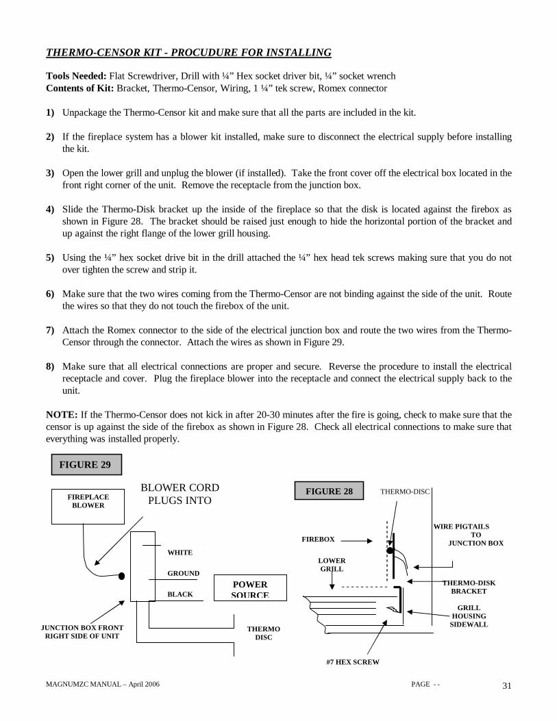
THERMO-CENSOR KIT - PROCUDURE FOR INSTALLING
Tools Needed: Flat Screwdriver, Drill with ¼” Hex socket driver bit, ¼” socket wrenchContents of Kit: Bracket, Thermo-Censor, Wiring, 1 ¼” tek screw, Romex connector
1) Unpackage the Thermo-Censor kit and make sure that all the parts are included in the kit.
2) If the fireplace system has a blower kit installed, make sure to disconnect the electrical supply before installingthe kit.
3) Open the lower grill and unplug the blower (if installed). Take the front cover off the electrical box located in thefront right corner of the unit. Remove the receptacle from the junction box.
4) Slide the Thermo-Disk bracket up the inside of the fireplace so that the disk is located against the firebox asshown in Figure 28. The bracket should be raised just enough to hide the horizontal portion of the bracket andup against the right flange of the lower grill housing.
5) Using the ¼” hex socket drive bit in the drill attached the ¼” hex head tek screws making sure that you do notover tighten the screw and strip it.
6) Make sure that the two wires coming from the Thermo-Censor are not binding against the side of the unit. Routethe wires so that they do not touch the firebox of the unit.
7) Attach the Romex connector to the side of the electrical junction box and route the two wires from the Thermo-Censor through the connector. Attach the wires as shown in Figure 29.
8) Make sure that all electrical connections are proper and secure. Reverse the procedure to install the electricalreceptacle and cover. Plug the fireplace blower into the receptacle and connect the electrical supply back to theunit.
NOTE: If the Thermo-Censor does not kick in after 20-30 minutes after the fire is going, check to make sure that thecensor is up against the side of the firebox as shown in Figure 28. Check all electrical connections to make sure thateverything was installed properly.
FIGURE 28 THERMO-DISC
WIRE PIGTAILSTO
JUNCTION BOX
#7 HEX SCREW
THERMO-DISKBRACKET
GRILLHOUSING
SIDEWALL
POWERSOURCE
JUNCTION BOX FRONTRIGHT SIDE OF UNIT
FIGURE 29
FIREPLACEBLOWER
BLOWER CORDPLUGS INTO
WHITE
GROUND
BLACK
THERMODISC
LOWERGRILL
FIREBOX
MAGNUMZC MANUAL – April 2006 PAGE - - 32
GAS LOG SETUP HOLE LOCATION
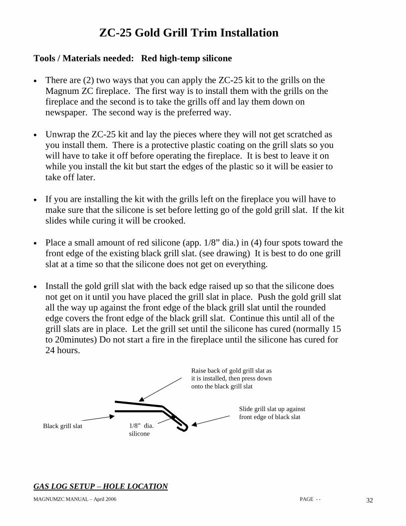
ZC-25 Gold Grill Trim Installation
Tools / Materials needed: Red high-temp silicone
• There are (2) two ways that you can apply the ZC-25 kit to the grills on theMagnum ZC fireplace. The first way is to install them with the grills on thefireplace and the second is to take the grills off and lay them down onnewspaper. The second way is the preferred way.
• Unwrap the ZC-25 kit and lay the pieces where they will not get scratched asyou install them. There is a protective plastic coating on the grill slats so youwill have to take it off before operating the fireplace. It is best to leave it onwhile you install the kit but start the edges of the plastic so it will be easier totake off later.
• If you are installing the kit with the grills left on the fireplace you will have tomake sure that the silicone is set before letting go of the gold grill slat. If the kitslides while curing it will be crooked.
• Place a small amount of red silicone (app. 1/8” dia.) in (4) four spots toward thefront edge of the existing black grill slat. (see drawing) It is best to do one grillslat at a time so that the silicone does not get on everything.
• Install the gold grill slat with the back edge raised up so that the silicone doesnot get on it until you have placed the grill slat in place. Push the gold grill slatall the way up against the front edge of the black grill slat until the roundededge covers the front edge of the black grill slat. Continue this until all of thegrill slats are in place. Let the grill set until the silicone has cured (normally 15to 20minutes) Do not start a fire in the fireplace until the silicone has cured for24 hours.
Black grill slat 1/8” dia.silicone
Slide grill slat up againstfront edge of black slat
Raise back of gold grill slat asit is installed, then press downonto the black grill slat
MAGNUMZC MANUAL – April 2006 PAGE - - 33
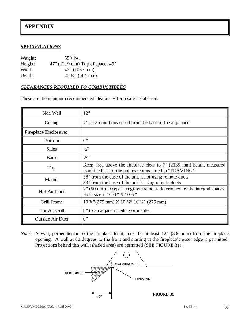
SPECIFICATIONS
Weight: 550 lbs.Height: 47” (1219 mm) Top of spacer 49”Width: 42” (1067 mm)Depth: 23 ½” (584 mm)
CLEARANCES REQUIRED TO COMBUSTIBLES
These are the minimum recommended clearances for a safe installation.
Side Wall 12”
Ceiling 7’ (2135 mm) measured from the base of the appliance
Fireplace Enclosure:
Bottom 0”
Sides ½”
Back ½”
Top Keep area above the fireplace clear to 7’ (2135 mm) height measuredfrom the base of the unit except as noted in “FRAMING”
Mantel 58” from the base of the unit if not using remote ducts53” from the base of the unit if using remote ducts
Hot Air Duct 2” (50 mm) except at register frame as determined by the integral spaces.Hole size is 10 ¾” X 10 ¾”
Grill Frame 10 ¾”(275 mm) X 10 ¾” 10 ¾” (275 mm)
Hot Air Grill 8” to an adjacent ceiling or mantel
Outside Air Duct 0”
Note: A wall, perpendicular to the fireplace front, must be at least 12” (300 mm) from the fireplaceopening. A wall at 60 degrees to the front and starting at the fireplace’s outer edge is permitted.Projections behind this wall (shaded area) are permitted (SEE FIGURE 31).
APPENDIX
12”
MAGNUM ZC
OPENING
60 DEGREES
FIGURE 31
MAGNUMZC MANUAL – April 2006 PAGE - - 34
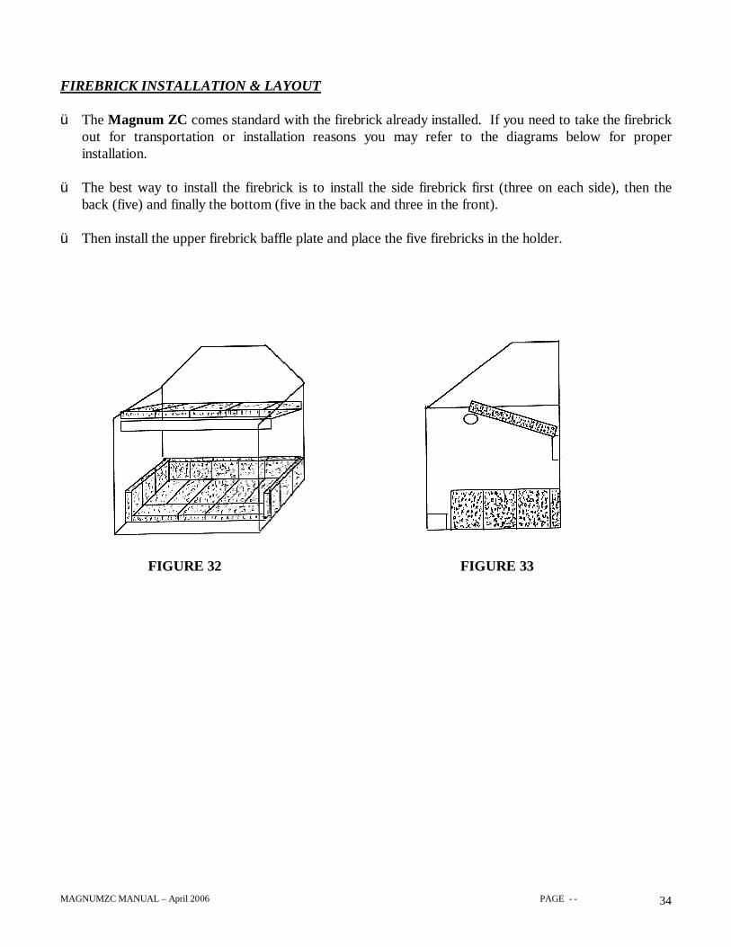
FIREBRICK INSTALLATION & LAYOUT
ü The Magnum ZC comes standard with the firebrick already installed. If you need to take the firebrickout for transportation or installation reasons you may refer to the diagrams below for properinstallation.
ü The best way to install the firebrick is to install the side firebrick first (three on each side), then theback (five) and finally the bottom (five in the back and three in the front).
ü Then install the upper firebrick baffle plate and place the five firebricks in the holder.
FIGURE 32 FIGURE 33
MAGNUMZC MANUAL – April 2006 PAGE - - 35
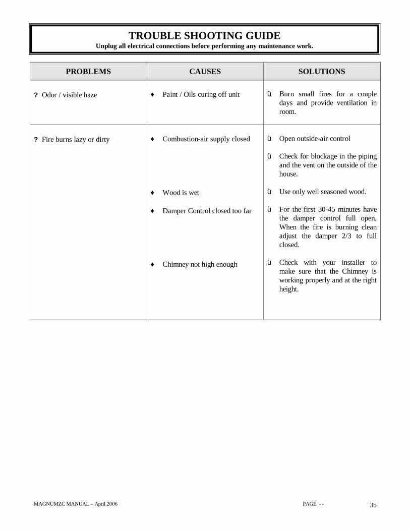
PROBLEMS CAUSES SOLUTIONS
? Odor / visible haze ♦ Paint / Oils curing off unit ü Burn small fires for a coupledays and provide ventilation inroom.
? Fire burns lazy or dirty ♦ Combustion-air supply closed
♦ Wood is wet
♦ Damper Control closed too far
♦ Chimney not high enough
ü Open outside-air control
ü Check for blockage in the pipingand the vent on the outside of thehouse.
ü Use only well seasoned wood.
ü For the first 30-45 minutes havethe damper control full open.When the fire is burning cleanadjust the damper 2/3 to fullclosed.
ü Check with your installer tomake sure that the Chimney isworking properly and at the rightheight.
TROUBLE SHOOTING GUIDEUnplug all electrical connections before performing any maintenance work.
MAGNUMZC MANUAL – April 2006 PAGE - - 36
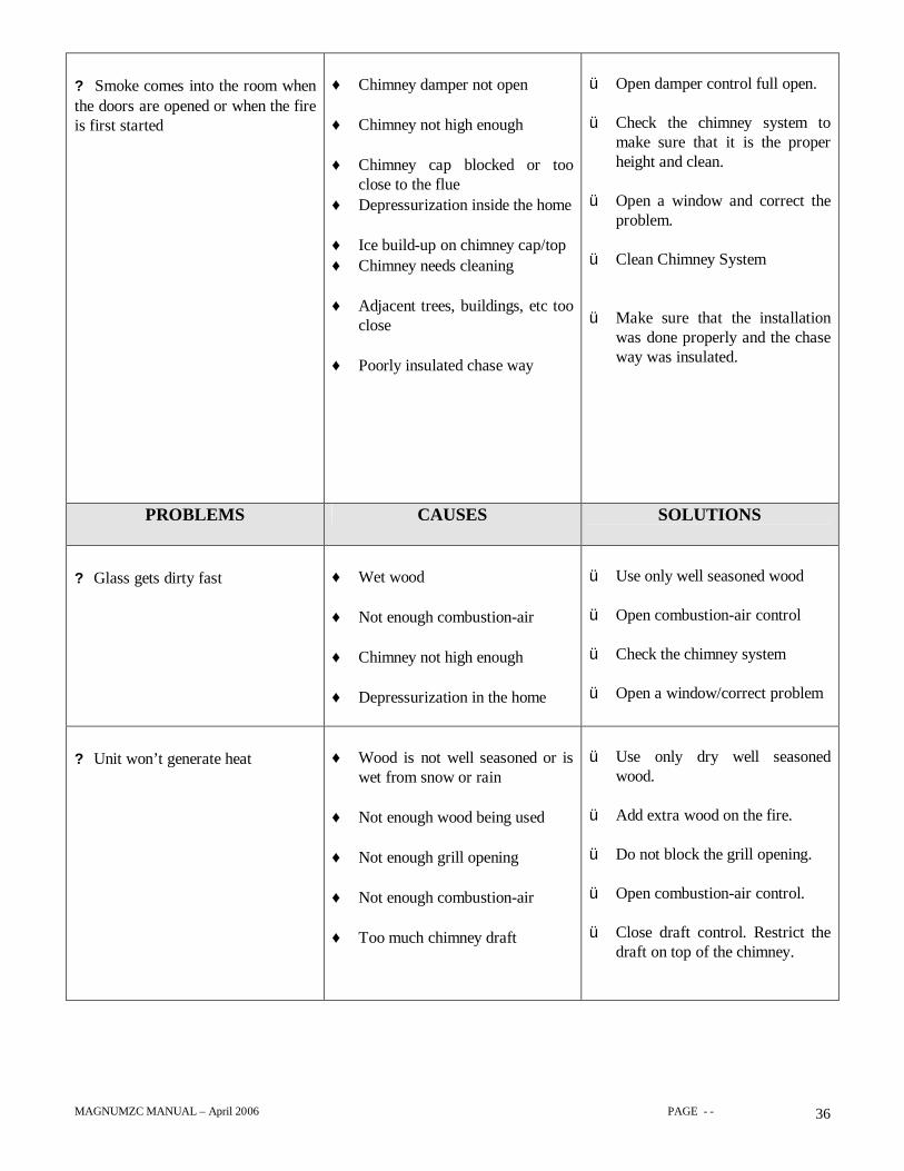
? Smoke comes into the room whenthe doors are opened or when the fireis first started
♦ Chimney damper not open
♦ Chimney not high enough
♦ Chimney cap blocked or tooclose to the flue
♦ Depressurization inside the home
♦ Ice build-up on chimney cap/top♦ Chimney needs cleaning
♦ Adjacent trees, buildings, etc tooclose
♦ Poorly insulated chase way
ü Open damper control full open.
ü Check the chimney system tomake sure that it is the properheight and clean.
ü Open a window and correct theproblem.
ü Clean Chimney System
ü Make sure that the installationwas done properly and the chaseway was insulated.
PROBLEMS CAUSES SOLUTIONS
? Glass gets dirty fast ♦ Wet wood
♦ Not enough combustion-air
♦ Chimney not high enough
♦ Depressurization in the home
ü Use only well seasoned wood
ü Open combustion-air control
ü Check the chimney system
ü Open a window/correct problem
? Unit won’t generate heat ♦ Wood is not well seasoned or iswet from snow or rain
♦ Not enough wood being used
♦ Not enough grill opening
♦ Not enough combustion-air
♦ Too much chimney draft
ü Use only dry well seasonedwood.
ü Add extra wood on the fire.
ü Do not block the grill opening.
ü Open combustion-air control.
ü Close draft control. Restrict thedraft on top of the chimney.

MAGNUMZC MANUAL – April 2006 PAGE - - 37
LIMITED WARRANTY AND 25 YEAR PROTECTION PLANLIMITED WARRANTY
This warranty is issued by American Energy Systems, Inc. (Manufacturer) and extends only to the original purchaser of this product.
This limited warranty will not become effective unless you have returned the attached warranty card within 30 days of your purchase. If you fail to do so,you may make no claim under this warranty. American Energy Systems, Inc. excludes and disclaims all implied warranties including, but not limited to,the implied warranty of merchantability.
For a period of (five) 5 years from the original purchase, Manufacturer will warrant, to the original consumer-purchaser, that all steel components are freefrom defects in materials and workmanship. There is expressly no warranty on firebrick, baffles, paint or gasketing material. Ceramic glass carries alifetime warranty. The original manufacturer covers all electrical components, for a period of one year from the original purchase date.
The warranty covers defects in materials and workmanship in covered components, provided the product has been installed and operated strictly inaccordance with manufacturers printed instructions. This warranty does not cover damage or breakage due or caused by mishandling, freight damage ormisuse or unauthorized modification of the structure or electrical system.
In the event of a defect within warranty guidelines the first year, American Energy Systems, Inc. will repair or at its option, replace the defective partentirely at its own expense. Within the second year through the fifth year after purchase, American Energy Systems, Inc. will, at its option, repair or supplyreplacement parts on this schedule: Second year, customer must pay one-fifth (1/5) of the current retail cost of repair of replacement, Third year, two-fifths(2/5); Fourth year, three-fifths (3/5); Fifth year, (4/5). American Energy Systems, Inc. will pay the balance of the expenses.
After expiration of the above five-year warranty and through the 25th year, American Energy Systems, Inc. will sell to you, F.O.B. its factory, a replacementpart or parts (if available) at its then current minimum list price. AMERICAN ENERGY SYSTEMS, INC. SHALL NOT BE RESPONSIBLE FORANY LABOR, TRANSPORTATION OR OTHER COSTS OR EXPENSES.
Repair or replacement may be obtained by returning part or parts freight prepaid to the nearest MAGNUM dealer or if you require additional informationregarding performance under this warranty, you may contact American Energy Systems, Inc. at the address listed below.
MAGNUM fireplaces have been designed for use with wood only. American Energy Systems, Inc. will not warrant performance of unit with manufacturedor pressed logs.
Discoloration and distortion of the inner firebox should be expected under normal use. American Energy Systems, Inc. shall not be responsible for thisnatural occurrence. 24K Gold plated doors are covered under a separate Warranty plan.
Neither the Manufacturer, nor the Reseller to the purchaser, accepts responsibility, legal or otherwise, for incidental or consequential damage to property ofpersons resulting from the use of this product. Any warranty implied by law, including but not limited to implied warranties of merchantability or fitness,shall be limited to one year from the date of original purchase. Whether a claim is made against the Manufacturer based on a breach of this warranty or anyother type of warranty, expressed or implied by law, Manufacturer shall in no event be liable for any special, indirect, consequential or other damages ofany nature whatsoever in excess of the original purchase price of this product. All warranties by Manufacturer are set forth herein and no claim shall bemade against Manufacturer on any oral warranty or representation.
Some states do not allow the exclusion or limitation of consequential damages, or limitations of implied warranties, so the limitations or exclusions set forthin this warranty may not apply to you. This warranty gives you specific legal rights and you may also have other rights, which vary, from state to state.
ALL CLAIMS UNDER THIS WARRANTY MUST BE MADE IN WRITING TO THE MANUFACTURER AT:
AMERICAN ENERGY SYSTEMS, INC., 150 Michigan Street S. E., Hutchinson, Minnesota 55350
Included with the claim needs to be the following:
Name, address and telephone number of local reseller or representative.Name, address and telephone number of the original purchaser.Date of purchase along with the model and serial number of the unit.Nature of defect and procedures of what has been done to correct the problem.
óóóóóóóóóóóóóóóóóóóóóóóóóóóóóóóóóóóóóó
NAME OF DEALER:_____________________ADDRESS:___________________________PHONE #:_______________
DATE OF PURCHASE:___________________ NAME OF INSTALLER:__________________DATE OF INSTALL:__________
MAGNUM MODEL:_________________________ SERIAL NUMBER:____________________________
MAGNUMZC MANUAL – April 2006 PAGE - - 38
LIMITED WARRANTYON CAST IRON PLATED DOORS
Following is a breakdown of the warranty of all of the Magnum cast iron plated doors. Please readthis warranty so that you are aware of the limitations and warranty conditions.
American Energy Systems, Inc. will warranty its cast iron plated doors under the followingconditions:
1) Plated cast iron doors are warranted to be free of defects at the time of purchase. Small holesand minor discoloration are common in cast iron, and are not considered to be defects.
2) When the doors are delivered to dealers, they are checked for scratches. Doors will NOT bewarranted for scratches caused by the consumer. American Energy Systems, Inc. will re-platescratched doors at cost for the customer as a service to them.
3) Plated cast iron doors are NOT warranted for discoloration of platingdue to overheating, abuse or cleaners used to clean glass.
4) Proper cleaning materials must be used on the different types of plating (24k gold, nickel,antique brass) to insure their finished is maintained. Polishing cleaners can be purchased fromyour local Magnum reseller.
AMERICAN ENERGY SYSTEMS, INC.150 Michigan Street SE – HUTCHINSON, MINNESOTA 55350
(320) 587-6565 PHONE – (320) 587-8872 FAXemail: [email protected] www.magnumheat.com


![Discriminacion zc f[1]](https://img.pdfslide.net/doc/110x75/5595f3351a28ab6a0e8b4843/discriminacion-zc-f1.jpg)