Embed Size (px)
Citation preview

Making your own RCX-sensors Claude Baumann
The RCX belongs to the large set of inter-connectable pieces known as the LEGO technic system. This trivial affirmation is not as obvious as it might appear at first sight. In fact the RCX-builders have solved the problem to pack together unfamiliar electronics parts, wires, LCD-display, buttons and batteries into a friendly yellow box that may easily be included into animated LEGO constructions. Thanks to the sophisticated geometry and physical characteristics, the number of useful combinations is literally unlimited. Only looking to the large gallery of robots that have been realized since the LEGO Mindstorms release in 1998, one can hardly imagine that an end of diversity will ever be reached. And diversity is one of the most important differences to other robot kits, which all have much more limited possibilities.
The RCX is a most astonishing invention. In an environment that has known such an incredible progress during the last decade -only think of the GHz processor clock-rate or GB-memory - a 32kB, 16MHz, 4-button computer with 3 input ports, 3 output ports, a 4-digit display, 2400 baud communication looks like a medieval device, spoken in computer era terms. What is its secret, that for 7 years now people -kids, amateurs, students and even engineers- keep on developing, studying and inventing with it? Looking back to 1998, despite the enormous and expensive efforts and investments, the success was by no means certain. Initially designed for kids, however it rapidly was well received in the research and educational establishment and an incredible race was launched, animated by a strong achievement motivation, to somehow reach the end of what you can reasonably do with the brick.
Rather early after the RCX-release, a small of group of enthusiasts started developing small additional “homebrew” sensors that were destined to extend the official sensor-set. In the beginning hesitating in their designs, they invented clever, useful and cheap angle-sensors, light-sensors, thermometers, RCX input multiplexers… Most of the designers were students that just were experiencing their first steps in microelectronics. By this way, Mindstorms robotics became a new and efficient study field for the curious in understanding electronics in combination with mechanics and computers. Gradually the web together with several remarkable articles and books generated an avalanche of RCX compatible circuits that become more and more sophisticated.
Our own Internet site has grown to a real reference in that particular field, perhaps because we deliberately shared complete designs, schematics, software and even development journals with the rest of the world. Our sensors rapidly covered a wide area and all degrees of difficulty, where the most important topics are electronic compasses, sound sensors, rotation and angle sensors, ultrasonic and infrared devices, … In any case they were developed by students under skilled guidance that wanted to build particular robots with extended capabilities that apparently couldn’t have been realized with the existing sensor set. In parallel, some students found it more exciting – and in their reach – to prove that the original LEGO sensors could easily be converted into versatile powerful devices.
This is why our sensors can be divided into two major classes :
LEGO-only devices LEGO compatible devices
The first class is characterized by the restriction that no additional electronics are tolerated. By contrast the second sensor-class isn’t limited by any rules. This paper will essentially talk about the first class of sensors.
LEGO-only sensors
It is very challenging and a perfect exercise of ingenuity, if the students are imposed the restriction of sticking to “what they have”. To be precise, the constraints are formulated as follows: “You will not alter any LEGO piece” or in other words, there will be no gluing, squeezing, cutting or any other misuse of LEGO parts. Sometimes it is necessary to also limit the field of additional non-LEGO parts. Paper shaft encoders are excellent incarnations off this sensor-class. Various types of encoders can be designed.
1. Poor man’s rotation sensor
Those who have to manage carefully their resources can build a very simple but efficient rotation-sensor for low speed. The concept first was expressed in Ben Erwin's book Creative Projects with Lego Mindstorms page 201ff. The idea is quite simple. A paper disk with a special black and white pattern is attached to a 40 teeth gear. A LEGO light-sensor faces the disk and should notice the variations of light-intensity while the encoder is turning.
Pictures 1 & 2: A paper encoder that can transform the LEGO light-sensor into a rotation sensor
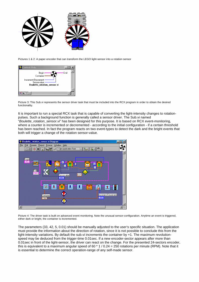
Picture 3: This Sub.vi represents the sensor driver task that must be included into the RCX program in order to obtain the desired functionality.
It is important to run a special RCX task that is capable of converting the light-intensity changes to rotation-pulses. Such a background function is generally called a sensor driver. The Sub.vi named “Boulette_rotation_sensor.vi” has been designed for this purpose. It is based on RCX event-monitoring, where a counter is incremented or decremented - according to the initial configuration - if a certain threshold has been reached. In fact the program reacts on two event-types to detect the dark and the bright events that both will trigger a change of the rotation sensor-value.
Picture 4: The driver task is built on advanced event monitoring. Note the unusual sensor-configuration. Anytime an event is triggered, either dark or bright, the container is incremented.
The parameters (33, 42, 5, 0.01) should be manually adjusted to the user’s specific situation. The application must provide the information about the direction of rotation, since it is not possible to conclude this from the light-intensity variations. By default the sub.vi increments the container by +1. The maximum revolution-speed may be deduced from the trigger-time 0.01sec. If a new encoder-sector appears after more than 0.01sec in front of the light-sensor, the driver can react on the change. For the presented 24-sectors encoder, this is equivalent to a maximum angular speed of 60 * 1 / 0.24 = 250 rotations per minute (RPM). Note that it is essential to determine the correct operation-range of any self-made sensor.
Picture 5: A typical test-program to get information about the sensor. It is absolutely necessary to know the operation range for future use in real robots.
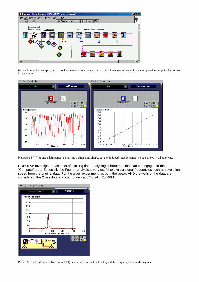
Pictures 6 & 7: The basic light-sensor signal has a sinusoidal shape, but the deduced rotation-sensor values evolve in a linear way.
ROBOLAB Investigator has a set of exciting data-analyzing subroutines that can be engaged in the “Compute” area. Especially the Fourier analysis is very useful to extract signal frequencies such as revolution speed from the original data. For the given experiment, as both the peaks AND the wells of the data are considered, the 24-sectors encoder rotates at 8*60/24 = 20 RPM.
Picture 8: The Fast Fourier Transform (FFT) is a most powerful function to yield the frequency of periodic signals.
Pictures 9 & 10: A shaft-encoder variant that also gives additional information about the sense of rotation. Realizing the driver for this encoder is more difficult and represents a serious challenge for advanced RCX-enthusiasts.
2. Astute angle sensor
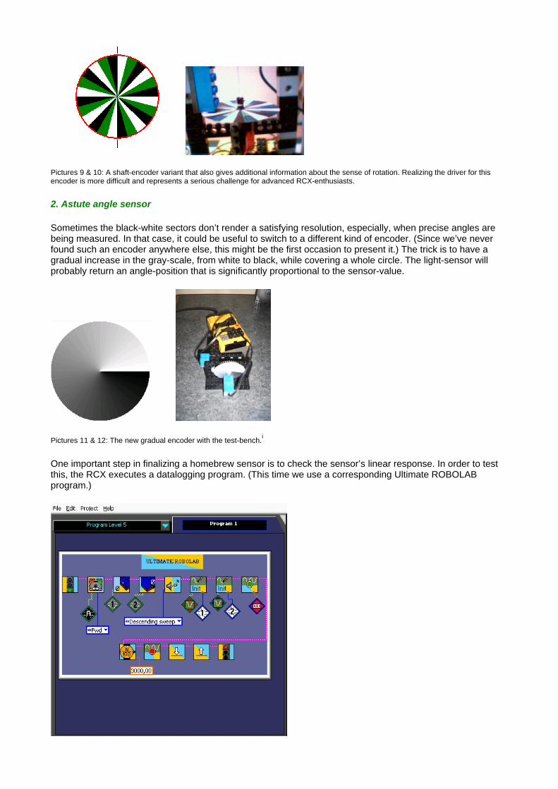
Sometimes the black-white sectors don’t render a satisfying resolution, especially, when precise angles are being measured. In that case, it could be useful to switch to a different kind of encoder. (Since we’ve never found such an encoder anywhere else, this might be the first occasion to present it.) The trick is to have a gradual increase in the gray-scale, from white to black, while covering a whole circle. The light-sensor will probably return an angle-position that is significantly proportional to the sensor-value.
Pictures 11 & 12: The new gradual encoder with the test-bench.i
One important step in finalizing a homebrew sensor is to check the sensor’s linear response. In order to test this, the RCX executes a datalogging program. (This time we use a corresponding Ultimate ROBOLAB program.)
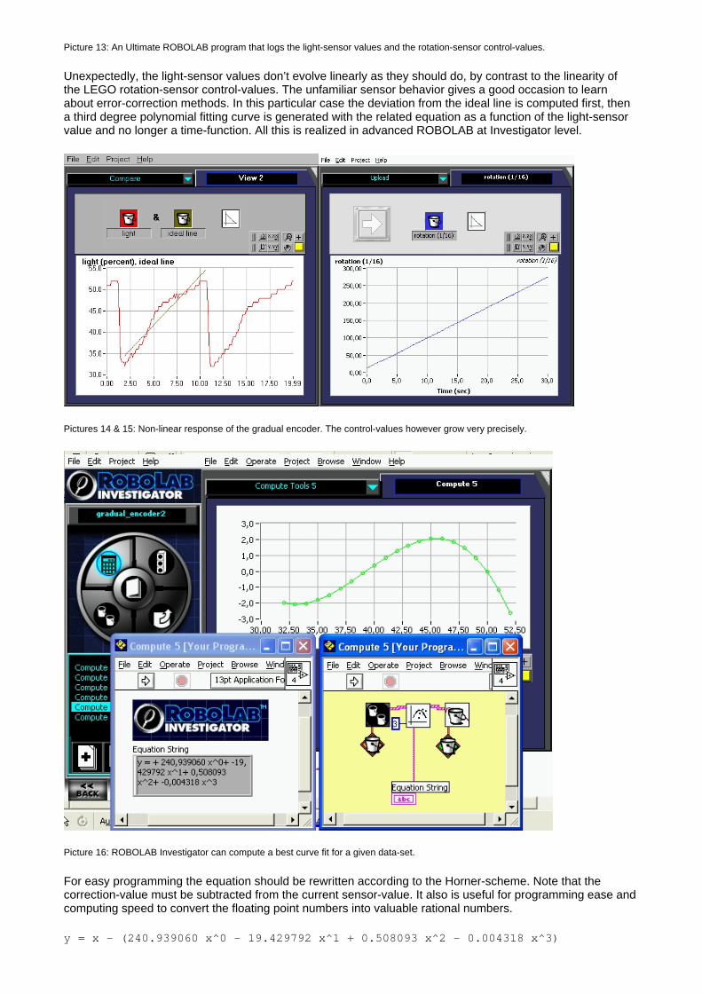
Picture 13: An Ultimate ROBOLAB program that logs the light-sensor values and the rotation-sensor control-values.
Unexpectedly, the light-sensor values don’t evolve linearly as they should do, by contrast to the linearity of the LEGO rotation-sensor control-values. The unfamiliar sensor behavior gives a good occasion to learn about error-correction methods. In this particular case the deviation from the ideal line is computed first, then a third degree polynomial fitting curve is generated with the related equation as a function of the light-sensor value and no longer a time-function. All this is realized in advanced ROBOLAB at Investigator level.
Pictures 14 & 15: Non-linear response of the gradual encoder. The control-values however grow very precisely.
Picture 16: ROBOLAB Investigator can compute a best curve fit for a given data-set.
For easy programming the equation should be rewritten according to the Horner-scheme. Note that the correction-value must be subtracted from the current sensor-value. It also is useful for programming ease and computing speed to convert the floating point numbers into valuable rational numbers.
y = x - (240.939060 x^0 - 19.429792 x^1 + 0.508093 x^2 - 0.004318 x^3)
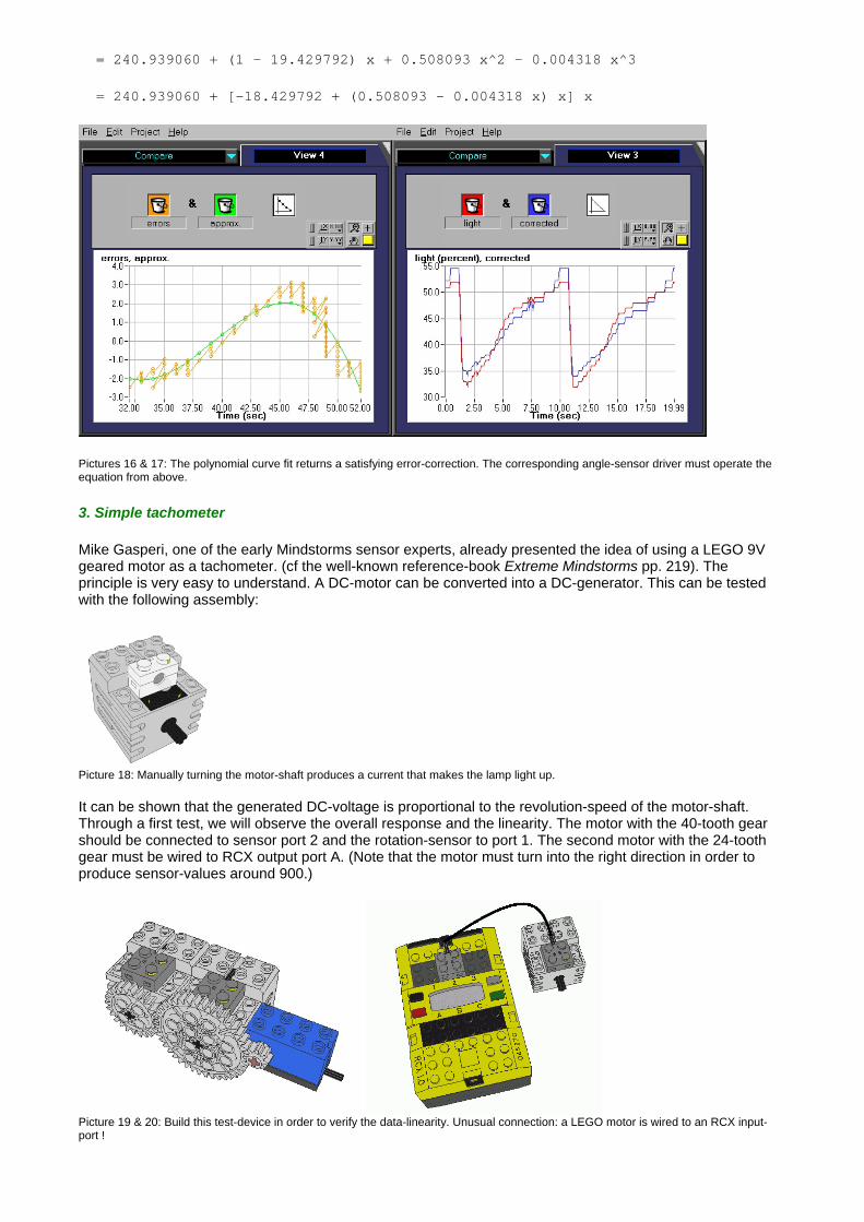
= 240.939060 + (1 - 19.429792) x + 0.508093 x^2 - 0.004318 x^3
= 240.939060 + [-18.429792 + (0.508093 - 0.004318 x) x] x
Pictures 16 & 17: The polynomial curve fit returns a satisfying error-correction. The corresponding angle-sensor driver must operate the equation from above.
3. Simple tachometer
Mike Gasperi, one of the early Mindstorms sensor experts, already presented the idea of using a LEGO 9V geared motor as a tachometer. (cf the well-known reference-book Extreme Mindstorms pp. 219). The principle is very easy to understand. A DC-motor can be converted into a DC-generator. This can be tested with the following assembly:
Picture 18: Manually turning the motor-shaft produces a current that makes the lamp light up. It can be shown that the generated DC-voltage is proportional to the revolution-speed of the motor-shaft. Through a first test, we will observe the overall response and the linearity. The motor with the 40-tooth gear should be connected to sensor port 2 and the rotation-sensor to port 1. The second motor with the 24-tooth gear must be wired to RCX output port A. (Note that the motor must turn into the right direction in order to produce sensor-values around 900.)
Picture 19 & 20: Build this test-device in order to verify the data-linearity. Unusual connection: a LEGO motor is wired to an RCX input-port !

Picture 21: This program first configures the datalogging for the two sensors, starts the motor at lowest power level, waits a power-up second and logs the data for 6 seconds. The result is most astonishing, since the tachometer values spread over a wide range from about 750 to 1020. This might suggest that either the motor speed hasn’t been constant during the experiment -and the sensor is sensitive enough to record the small variations-, or the sensor isn’t responding correctly. If we call the ROBOLAB Investigator “Compute” tool 2 with the integration function, the returned data represents a perfectly growing number of rotations. (Remember that integrating a velocity summates small portions of rotations over time!) The linearity of the integrated data suggests that the signal noise must be neutralized during the summations. So, where’s the problem?
Pictures 22: The returned voltage suggests that there must be something wrong about the improvised “tachometer”. But the integration of the data over time shows a perfect linearity.
Picture 23: Both the control-data of the rotation-sensor and the integrated data are linear. From the rotation values diagram we can conclude that the constant rotation-speed is (-)1458/5.9 = 247.118 rotation-pulses per second = 15.44 complete revolutions per second with 16 pulses per revolution. We have to consider the test-assembly gearing of 8:40. Thus the generator is rotating at 3.088 revolutions per second.
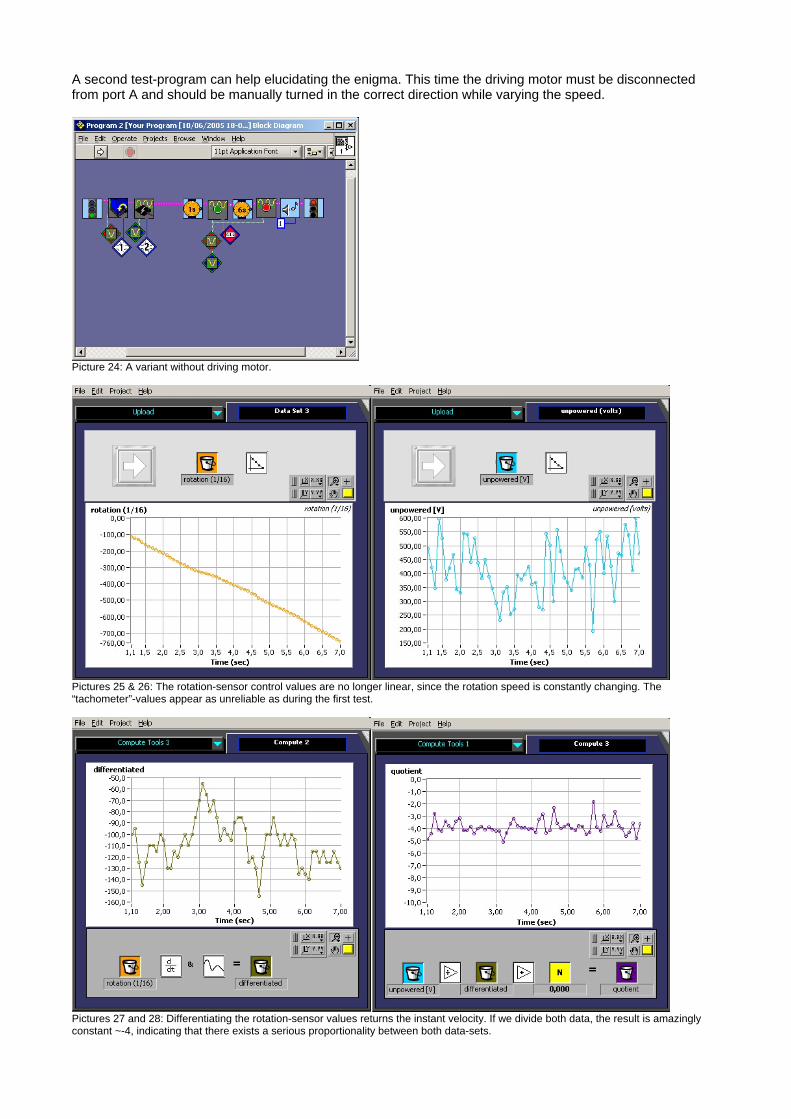
A second test-program can help elucidating the enigma. This time the driving motor must be disconnected from port A and should be manually turned in the correct direction while varying the speed.
Picture 24: A variant without driving motor.
Pictures 25 & 26: The rotation-sensor control values are no longer linear, since the rotation speed is constantly changing. The “tachometer”-values appear as unreliable as during the first test.
Pictures 27 and 28: Differentiating the rotation-sensor values returns the instant velocity. If we divide both data, the result is amazingly constant ~-4, indicating that there exists a serious proportionality between both data-sets.
Overlaying both the adjusted sensor values (each one multiplied by the constant factor -4) and the rotation-sensor derivate shows that there is an obvious relationship, which proves that the “tachometer” returns a valuable but rather disturbed data.
Pictures 29 & 30: The tachometer measures the velocity in an acceptable way. Adding an anti-aliasing filter significantly reduces the noise. (cut-off frequency 5Hz=half the datalogging rate, e.a. the initial values are averaged by couples of data-points) The signal that is recorded from the converted LEGO generator is extremely noisy. The reason must be searched in the LEGO “generator” - motor internals. This electro-mechanical device is composed of coils that are rotating in a constant magnetic field. Normally the anchor-revolutions would produce a sinusoidal AC-voltage, but for each half-wave the polarity is reversed in a DC-motor. The result is an inconstant voltage which polarity only depends on the sense of rotation.
Picture 30: A LEGO motor anchor composed of three coils and 6 connections. The motor brushes slip over the shaft and realize the polarity-reversing of the induced current.
Picture 31: Oscilloscope screen-shot of the generator signal. Each time the motor-brushes get contact to the next coil, a half-sinusoidal waveform is generated. Thus there are 6 half-waves per internal shaft revolution. The internal motor gearing is 10:43 * 12:36 = 10/129. We deduced above that the generator was turning at 3.088 revolutions per second. Therefore the noise signal must have a frequency of 3.088 * 12.9 * 6 = 239 periodic sinusoidal half-waves per second. This rather rapid noise, compared to the slow rotation speed, must be filtered out of the data. The original sensor-data has been logged at only 10Hz. The result is a typical aliased signal. There exists an important rule, called the

Shannon-rule, saying that any data-variation faster than half the sampling rate may not transport any reliable information. The RCX, running under the standard firmware, is able to sample at about 300Hz, which is much faster than the datalogging rate, but still not fast enough to include all the data. But a faster sampling would only be necessary, if we wanted to make visible the waveforms as shown in the oscilloscope-diagram. (Note that Ultimate ROBOLAB allows sensor sampling at significantly higher rates up to 50kHz !)
Picture 32: These values were generated, logged and uploaded through an Ultimate ROBOLAB program. The sampling rate was 8kHz. 200 values represent an observation time of 25ms. Thus, 6 half-waves, the equivalent of one motor-anchor rotation, happen during this short time, which means that the half-waves appear at 240Hz. We can conclude here that a correct knowledge about a periodic or sometimes a-periodic signal-noise is essential before the homebrew sensor can be exploited in a satisfying way. Good filtering methods also are required. This would make the topic for more than one article. Perhaps the reader has noticed that the tachometer doesn’t work, if the rotation-direction is changed. The reason for this phenomenon is that the DC-motor produces a negative voltage, that the RCX is unable to read at the given configuration. 4. High precision angle-sensor This experiment proposes a rather unorthodox operation of the LEGO touch-sensor. It is important to insist on the fact that the sensor is considered as an “unpowered” device. Unlike the LEGO light-sensor or the rotation-sensor, the touch-sensor is made of only one “passive” electronics part - a variable resistor for instance-, by contrast to “active” parts like transistors or microchips. Normally the touch-sensor works as a simple switch, and the RCX sensor port is configured accordingly to produce a “Boolean” result with only two possible values: 0 -or button released and 1 -button pressed. However, the LEGO touch-sensor is capable of much more, because its electrical resistance depends on the button pressure. This experiment will demonstrate that the touch-sensor can be used as an astonishingly precise angle-sensor.
Pictures 33 & 34: The test assembly for the converted angle-sensor experiment. Note the use of the eccentric cam.

To increase the datalogging precision, the RCX program is composed of Ultimate ROBOLAB icons. In fact, Ultimate ROBOLAB allows standard ROBOLAB compatible datalogging at higher rates. In the current example, the RCX logs at 100Hz.
Picture 35: Fast datalogging during about 16 seconds. Note that the RCX will display the word “full” after 15 seconds.
Pictures 36 & 37: The RCX has sampled many data-points. Note the narrow well at t1=8sec ! This represents the passage of the sharp end of the LEGO eccentric cam. We only are interested in the round end. Note the apparent linearity from t2=2.9 sec to t3=3.5 sec. From the diagrams and the shape of the eccentric cam we can conclude that the LEGO touch-sensor can be used as an angle-sensor with a high resolution of 700 single steps over the range of 45° ! Conclusions These are only a few examples of the first category of “homebrew” RCX sensors. However, they reveal a few important things to remember:
Simple devices may hide many unexpected features It is essential to study the operation range of any sensor-device Sometimes error-correction procedures must be applied to the raw sensor data One has to observe the rate at which the sensor is read and add an anti-aliasing filter, if necessary Data noise should be filtered out in any case
The presented sensors could be used in many interesting applications like mechanical compass, balance, pressure sensor, accelerometer, inclinometer, and so on. An example can be found at http://www.convict.lu/Jeunes/LEGO_Compass.htm
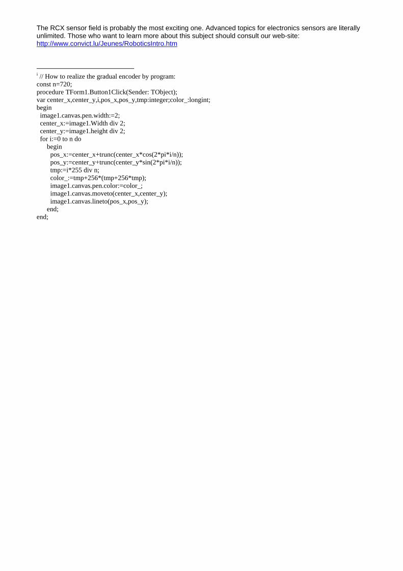
The RCX sensor field is probably the most exciting one. Advanced topics for electronics sensors are literally unlimited. Those who want to learn more about this subject should consult our web-site: http://www.convict.lu/Jeunes/RoboticsIntro.htm i // How to realize the gradual encoder by program: const n=720; procedure TForm1.Button1Click(Sender: TObject); var center_x,center_y,i,pos_x,pos_y,tmp:integer;color_:longint; begin image1.canvas.pen.width:=2; center_x:=image1.Width div 2; center_y:=image1.height div 2; for i:=0 to n do begin pos_x:=center_x+trunc(center_x*cos(2*pi*i/n)); pos_y:=center_y+trunc(center_y*sin(2*pi*i/n)); tmp:=i*255 div n; color_:=tmp+256*(tmp+256*tmp); image1.canvas.pen.color:=color_; image1.canvas.moveto(center_x,center_y); image1.canvas.lineto(pos_x,pos_y); end; end;