Embed Size (px)
Citation preview
Manual Soldering and Repair Challenges in the Lead-free Soldering Era
Inge Schildermans
Alcatel Bell, Geel
RoHS Gorinchem 23/11/05 — 2 All rights reserved © 2004, Alcatel
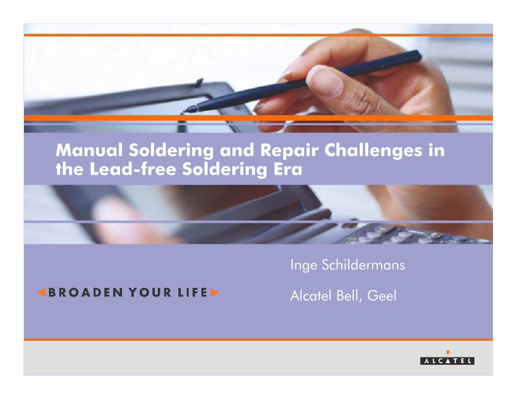
Introduction
> RoHS directive
> Solder processes
• Reflow soldering
• Wave soldering
RoHS Gorinchem 23/11/05 — 3 All rights reserved © 2004, Alcatel
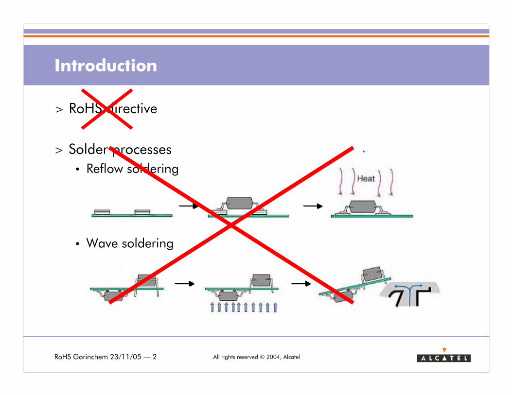
Content
1. Manual Soldering
> Introduction
> Lead-free solder wire evaluation
> Impact of higher melting temperature: a physics perspective
2. Component replacement (repair)
> Introduction
> Convection heating limitations
> Radiative heating: overcoming the limitations
RoHS Gorinchem 23/11/05 — 4 All rights reserved © 2004, Alcatel
1. Manual soldering: Introduction
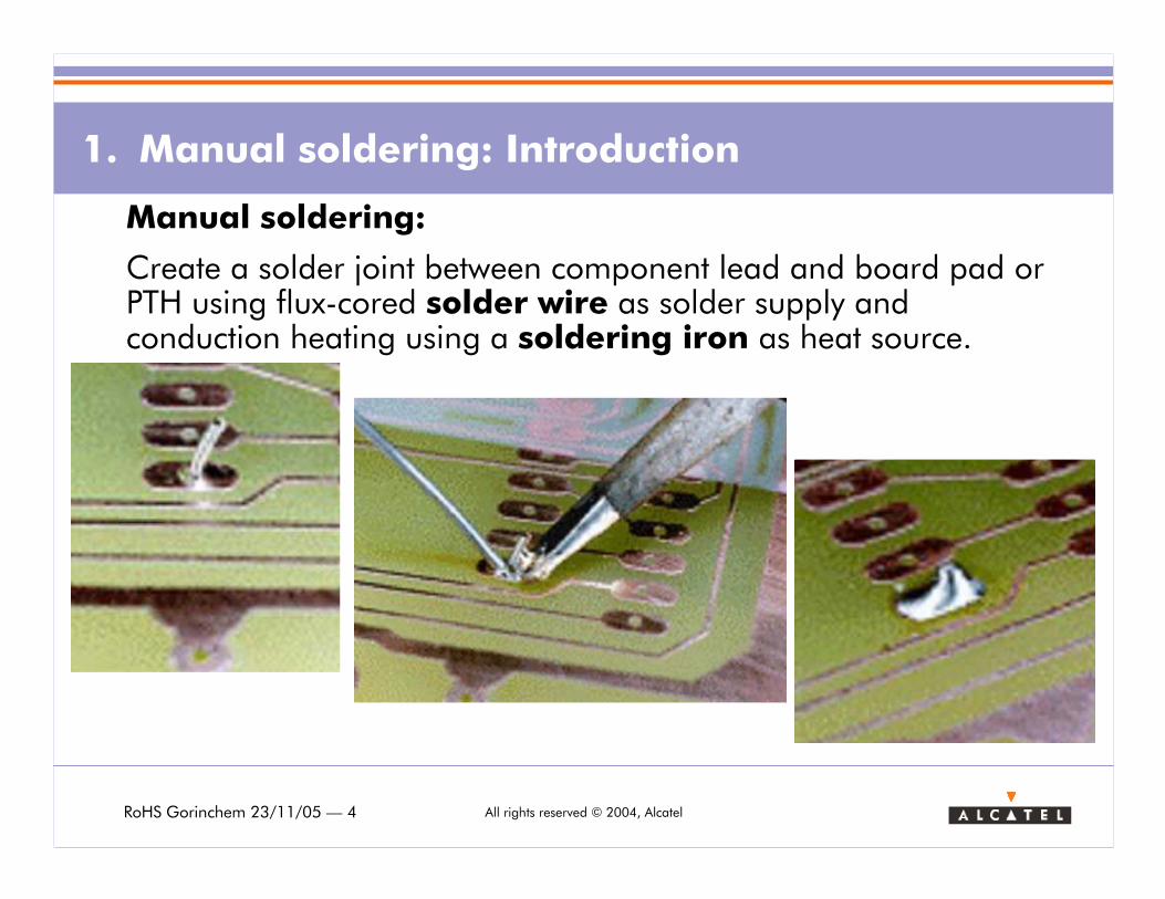
Manual soldering:
Create a solder joint between component lead and board pad or PTH using flux-cored solder wire as solder supply and conduction heating using a soldering iron as heat source.
RoHS Gorinchem 23/11/05 — 5 All rights reserved © 2004, Alcatel
1. Manual soldering: Introduction
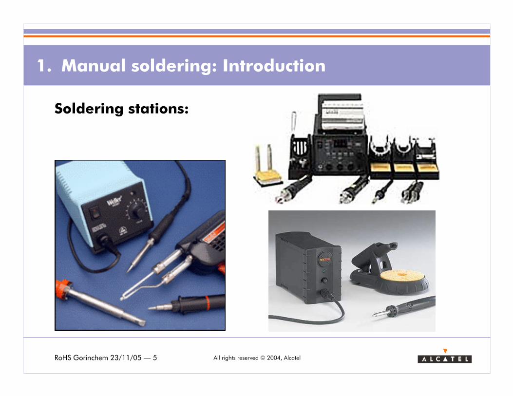
Soldering stations:
RoHS Gorinchem 23/11/05 — 6 All rights reserved © 2004, Alcatel
1. Manual soldering: Introduction
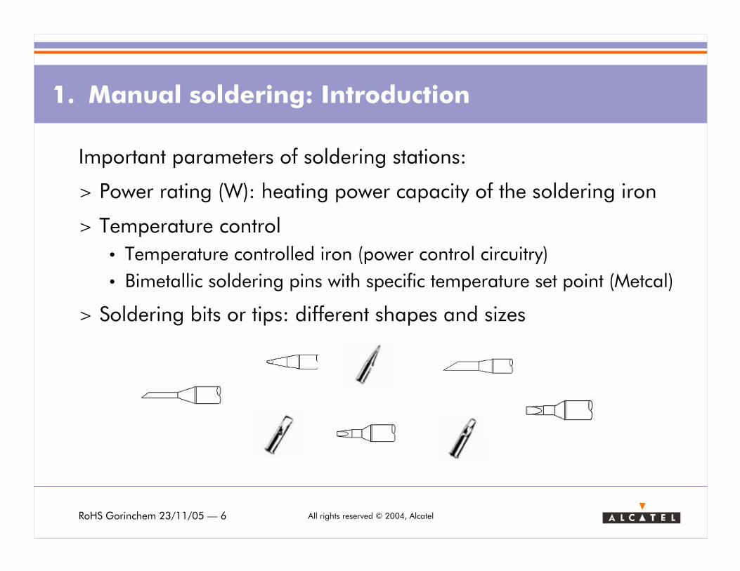
Important parameters of soldering stations:
> Power rating (W): heating power capacity of the soldering iron
> Temperature control
• Temperature controlled iron (power control circuitry)
• Bimetallic soldering pins with specific temperature set point (Metcal)
> Soldering bits or tips: different shapes and sizes
RoHS Gorinchem 23/11/05 — 7 All rights reserved © 2004, Alcatel
1. Manual soldering: Introduction
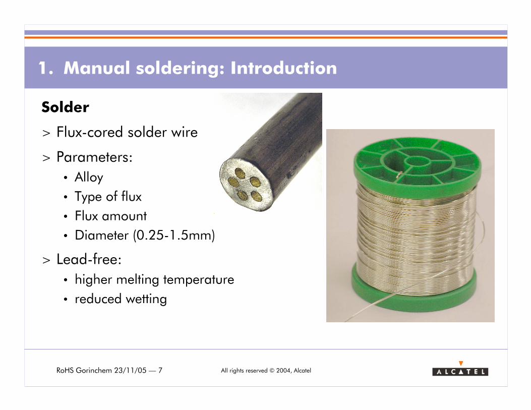
Solder
> Flux-cored solder wire
> Parameters:
• Alloy
• Type of flux
• Flux amount
• Diameter (0.25-1.5mm)
> Lead-free:
• higher melting temperature
• reduced wetting
RoHS Gorinchem 23/11/05 — 8 All rights reserved © 2004, Alcatel
1. Manual soldering: Lead-free solder wire evaluation
> Alloy choice: SnAg3-4%Cu0.5-0.7% is becoming the industries lead-
free alloy choice.
> Solder wiring evaluation:
• Contrary to solder pastes and fluxes there is very little standardisation around solder wire testing.
• Define solder wire requirements
• Define solder wire tests:– Reliability evaluation: corrosion, SIR, Electro-Migration
Wire performance requirements
– Control of flux amount
– Tackiness of flux remainders
– Flux spitting: contamination of PBA, esthetics, ergonomics
– Solderability test
> Flux-cored solder wires from different suppliers were evaluated.
RoHS Gorinchem 23/11/05 — 9 All rights reserved © 2004, Alcatel
Reliability requirements
> Evaluation of corrosiveness of fluxes
• J-STD-004 flux classification
• acceptable classes: L0, L1, (M0)
> SIR (Surface Insulation Resistance), electromigration evaluationaccording to telecommunication standard
• Telcordia (Bellcore): GR-78-CORE standard
> Test results supplied by solder material supplier
1. Manual soldering: Lead-free solder wire evaluation
RoHS Gorinchem 23/11/05 — 10 All rights reserved © 2004, Alcatel
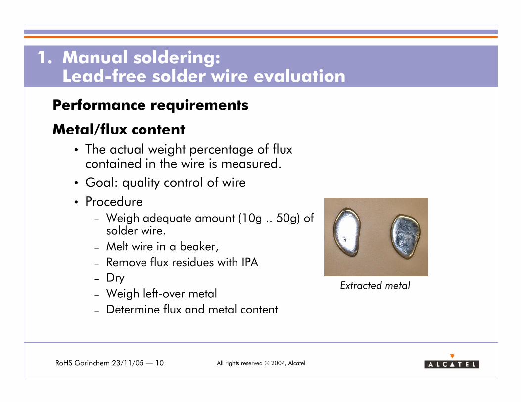
Performance requirements
Metal/flux content
• The actual weight percentage of flux contained in the wire is measured.
• Goal: quality control of wire
• Procedure– Weigh adequate amount (10g .. 50g) ofsolder wire.
– Melt wire in a beaker,
– Remove flux residues with IPA
– Dry
– Weigh left-over metal
– Determine flux and metal content
1. Manual soldering: Lead-free solder wire evaluation
Extracted metal
RoHS Gorinchem 23/11/05 — 11 All rights reserved © 2004, Alcatel
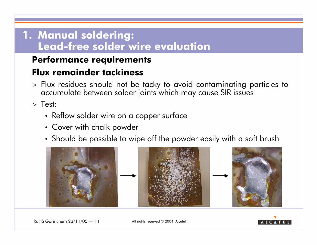
Performance requirements
Flux remainder tackiness
> Flux residues should not be tacky to avoid contaminating particles to accumulate between solder joints which may cause SIR issues
> Test:
• Reflow solder wire on a copper surface
• Cover with chalk powder
• Should be possible to wipe off the powder easily with a soft brush
1. Manual soldering: Lead-free solder wire evaluation
RoHS Gorinchem 23/11/05 — 12 All rights reserved © 2004, Alcatel
Performance requirements
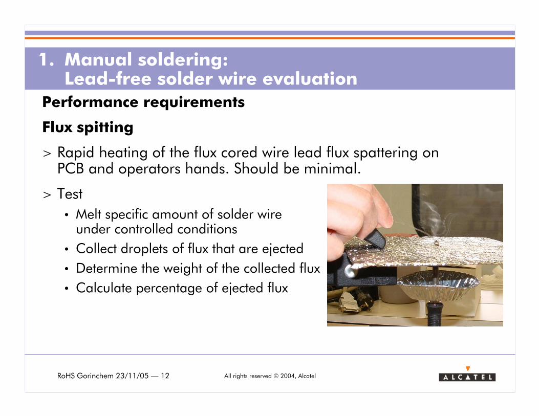
Flux spitting
> Rapid heating of the flux cored wire lead flux spattering on PCB and operators hands. Should be minimal.
> Test
• Melt specific amount of solder wireunder controlled conditions
• Collect droplets of flux that are ejected
• Determine the weight of the collected flux
• Calculate percentage of ejected flux
1. Manual soldering: Lead-free solder wire evaluation
RoHS Gorinchem 23/11/05 — 13 All rights reserved © 2004, Alcatel
Performance requirements
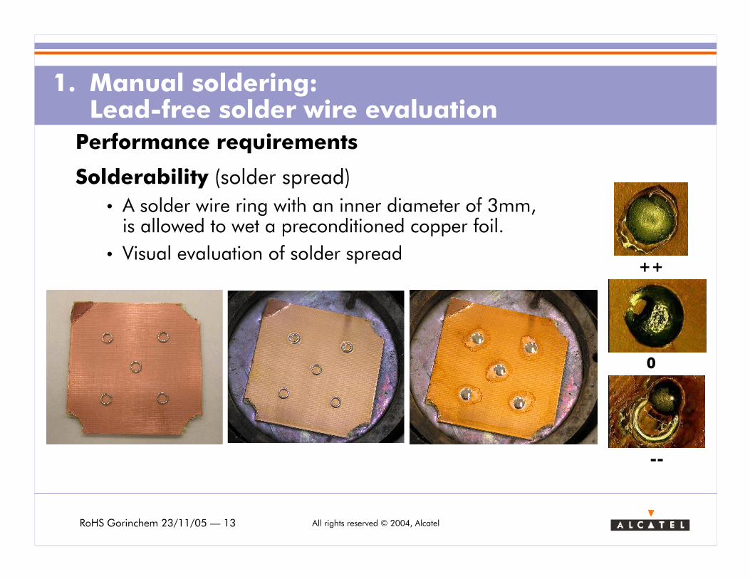
Solderability (solder spread)
• A solder wire ring with an inner diameter of 3mm, is allowed to wet a preconditioned copper foil.
• Visual evaluation of solder spread
1. Manual soldering: Lead-free solder wire evaluation
++
0
--
RoHS Gorinchem 23/11/05 — 14 All rights reserved © 2004, Alcatel
1. Manual soldering: Lead-free solder wire evaluation
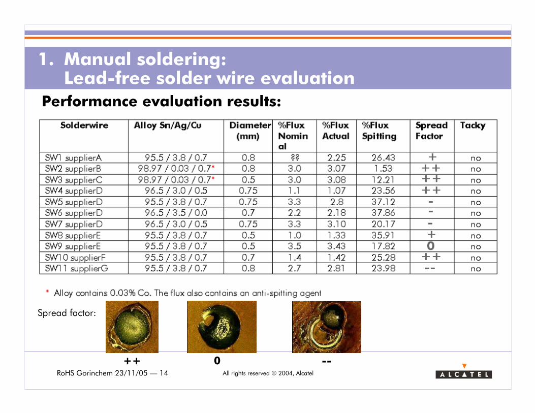
Spread factor:
++ 0 --
Performance evaluation results:
RoHS Gorinchem 23/11/05 — 15 All rights reserved © 2004, Alcatel
1. Manual soldering: Lead-free solder wire evaluation
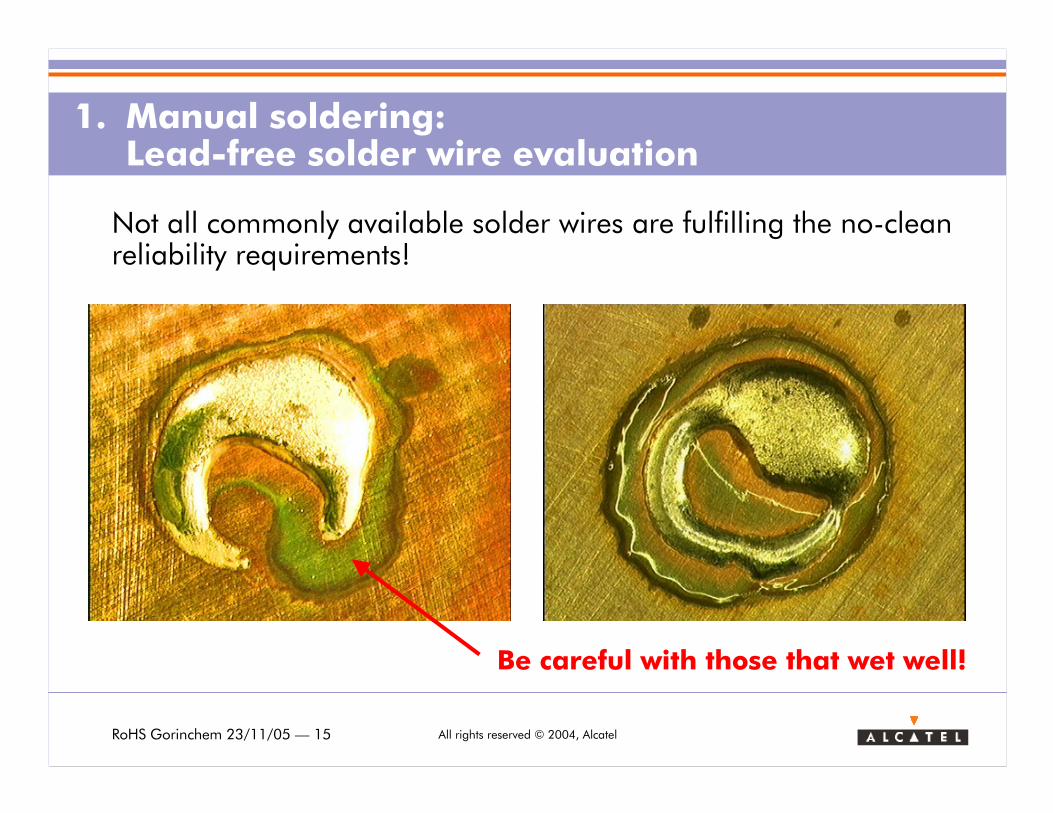
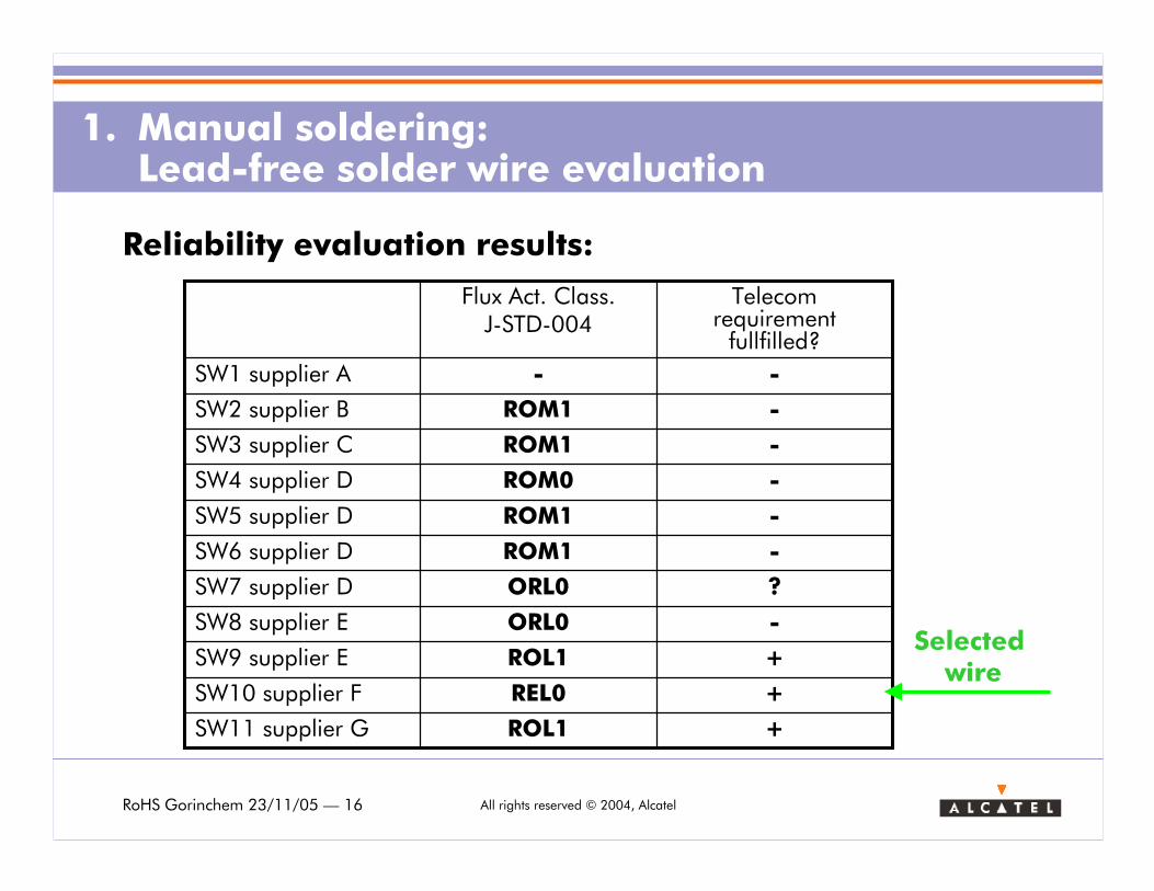
Not all commonly available solder wires are fulfilling the no-clean reliability requirements!
Be careful with those that wet well!
RoHS Gorinchem 23/11/05 — 16 All rights reserved © 2004, Alcatel
1. Manual soldering: Lead-free solder wire evaluation
Reliability evaluation results:
+ROL1SW11 supplier G
+REL0SW10 supplier F
+ROL1SW9 supplier E
-ORL0SW8 supplier E
?ORL0SW7 supplier D
-ROM1SW6 supplier D
-ROM1SW5 supplier D
-ROM0SW4 supplier D
-ROM1SW3 supplier C
-ROM1SW2 supplier B
--SW1 supplier A
Telecom requirement fullfilled?
Flux Act. Class.J-STD-004
Selected wire
RoHS Gorinchem 23/11/05 — 17 All rights reserved © 2004, Alcatel
How to define the manual soldering process parameters?
Parameters on which the temperature of the soldering area depends:
• PBA/PCB: thickness, build-up, land/PTH-size, material (thermal conductivity, thermal capacity), component to be soldered,...
• Soldering iron: set temperature, power, thermal capacity, temperature control, tip properties (dimensions, shape, material,...),...
• Soldering method: solder supply, board preheating temperature, iron position, contact time,...
What approach should we take?
> Leave it to the (chinese) operator to find out?
> Set-up a 10+ parameter full-factorial Design-of-Experiments?
Let’s have a look at some basic thermal physics.
1. Manual soldering: Impact of higher melting temperature
RoHS Gorinchem 23/11/05 — 18 All rights reserved © 2004, Alcatel
1. Manual soldering: Impact of higher melting temperature
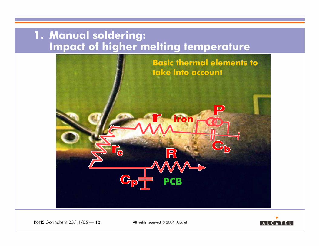
PCB
iron
Basic thermal elements totake into account
RoHS Gorinchem 23/11/05 — 19 All rights reserved © 2004, Alcatel
1. Manual soldering: Impact of higher melting temperature
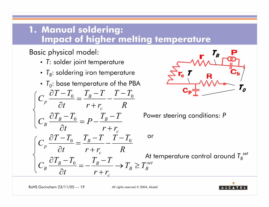
Basic physical model:
• T: solder joint temperature
• TB: soldering iron temperature
• T0: base temperature of the PBA
Power steering conditions: P
c
BBB
c
Bp
rr
TTP
t
TTC
R
TT
rr
TT
t
TTC
+−
−=∂−∂
−−
+−
=∂−∂
0
00
set
BB
c
BBB
c
Bp
TTrr
TT
t
TTC
R
TT
rr
TT
t
TTC
≥→+−
−=∂−∂
−−
+−
=∂−∂
0
00
At temperature control around TBset
or
T
TB
T0
RoHS Gorinchem 23/11/05 — 20 All rights reserved © 2004, Alcatel
1. Manual soldering: Impact of higher melting temperature
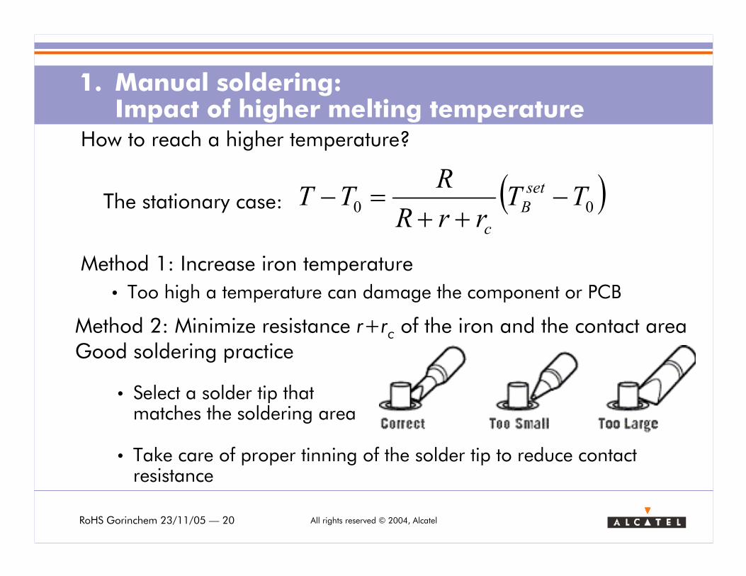
How to reach a higher temperature?
Method 1: Increase iron temperature
• Too high a temperature can damage the component or PCB
• Select a solder tip that matches the soldering area
• Take care of proper tinning of the solder tip to reduce contact resistance
( )00 TTrrR
RTT set
B
c
−++
=−The stationary case:
Method 2: Minimize resistance r+rc of the iron and the contact areaGood soldering practice
RoHS Gorinchem 23/11/05 — 21 All rights reserved © 2004, Alcatel
1. Manual soldering: Impact of higher melting temperature
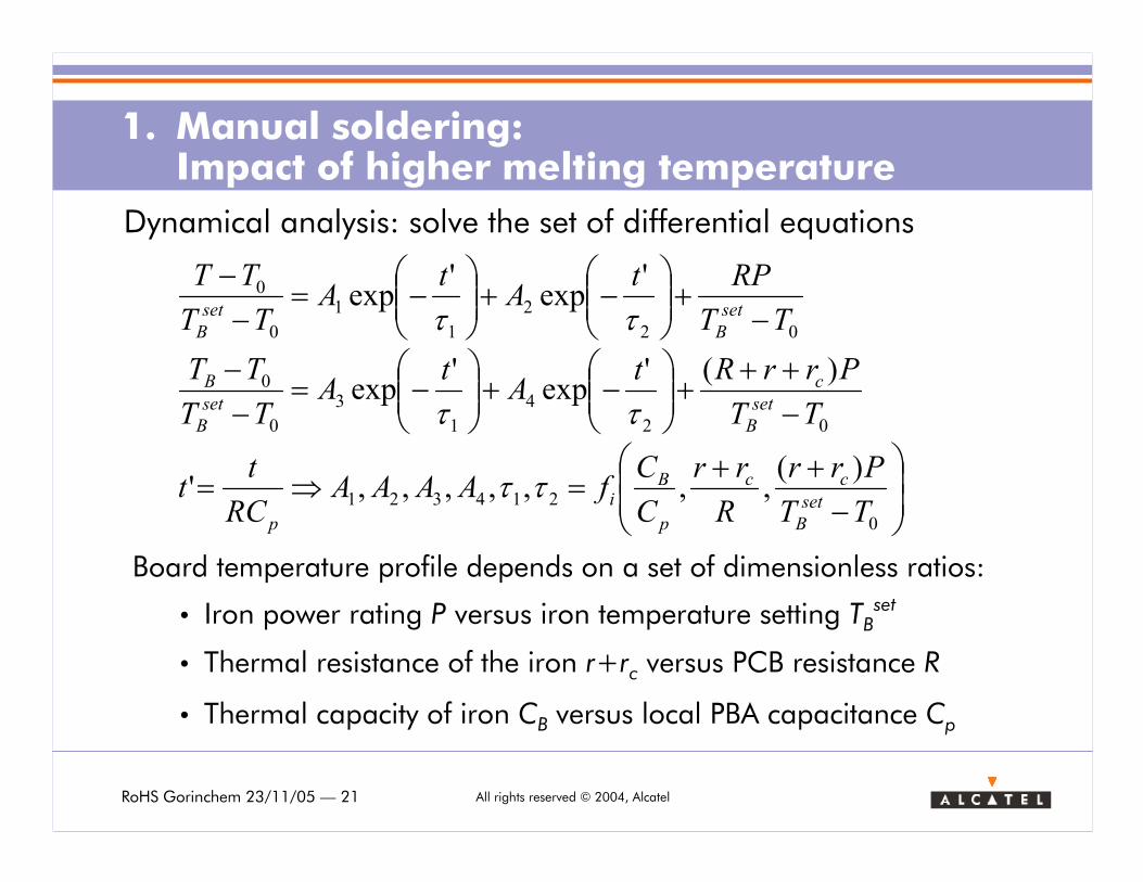
Dynamical analysis: solve the set of differential equations
−++
=⇒=
−++
+
−+
−=
−−
−+
−+
−=
−−
0
214321
02
4
1
3
0
0
02
2
1
1
0
0
)(,,,,,,,'
)('exp
'exp
'exp
'exp
TT
Prr
R
rr
C
CfAAAA
RC
tt
TT
PrrRtA
tA
TT
TT
TT
RPtA
tA
TT
TT
set
B
cc
p
Bi
p
set
B
c
set
B
B
set
B
set
B
ττ
ττ
ττ
Board temperature profile depends on a set of dimensionless ratios:
• Iron power rating P versus iron temperature setting TBset
• Thermal resistance of the iron r+rc versus PCB resistance R
• Thermal capacity of iron CB versus local PBA capacitance Cp
RoHS Gorinchem 23/11/05 — 22 All rights reserved © 2004, Alcatel
1. Manual soldering: Impact of higher melting temperature
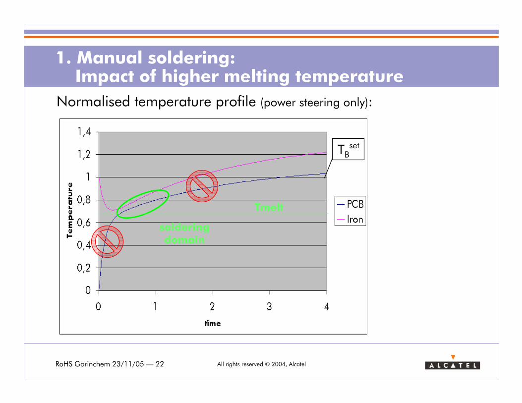
Normalised temperature profile (power steering only):
TBset
solderingdomain
Tmelt
RoHS Gorinchem 23/11/05 — 23 All rights reserved © 2004, Alcatel
1. Manual soldering: Impact of higher melting temperature
Conclusion
> For save soldering one needs to limit the soldering iron temperature while still meeting the higher melting temperature requirements of lead-free soldering.
> Soldering temperature conditions on the board should be obtained in a pre-defined region of the temperature profile for reproducible results.
> This should be done by carefully selecting soldering tips, ironsand the temperature/power setting in accordance with the thermal properties of the PBA to be soldered. Thermal capacity, thermal resistance and heating power are of major importance.
> Physical modelling gives a basic tool to master the large range of parameters influencing manual soldering.
RoHS Gorinchem 23/11/05 — 24 All rights reserved © 2004, Alcatel
Content
1. Manual Soldering
> Introduction
> Lead-free solder wire evaluation
> Impact of higher melting temperature: a physics perspective
2. Component replacement (repair)
> Introduction
> Convection heating limitations
> Radiative heating: overcoming the limitations

RoHS Gorinchem 23/11/05 — 25 All rights reserved © 2004, Alcatel
2. Component replacement: introduction
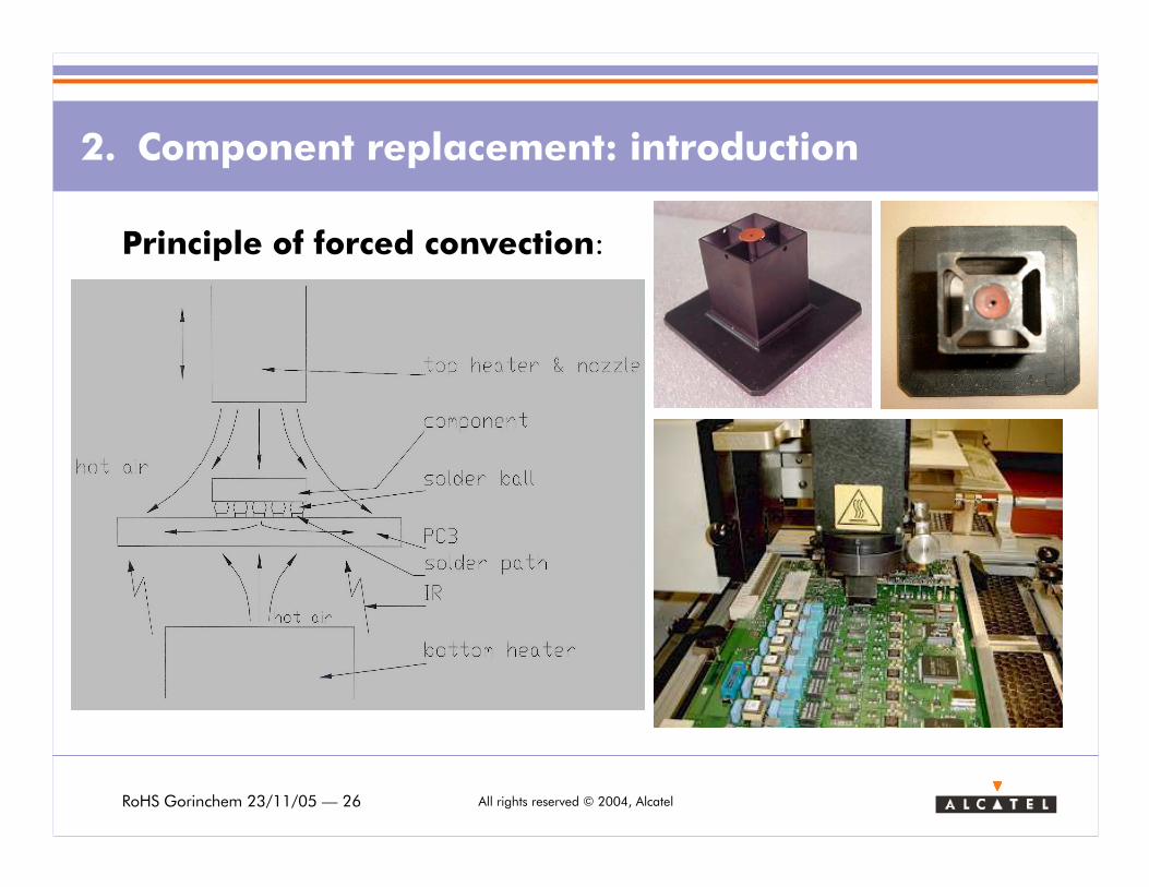
For components with interconnections under the body of the component,e.g., BGA (Ball Grid Array) and LLP (LeadLess Package)removal and resoldering the components using a soldering iron is not possible. Dedicated repair machines are required
Most of the machines are based on forced convection heating. A temperature profile approaching the standard reflow profile is used to replace these components.
RoHS Gorinchem 23/11/05 — 26 All rights reserved © 2004, Alcatel
2. Component replacement: introduction
Principle of forced convection:
RoHS Gorinchem 23/11/05 — 27 All rights reserved © 2004, Alcatel
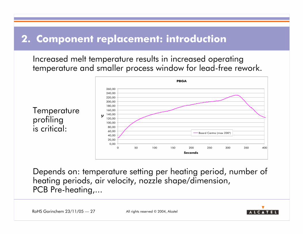
Depends on: temperature setting per heating period, number of heating periods, air velocity, nozzle shape/dimension, PCB Pre-heating,...
PBGA
0,00
20,00
40,00
60,00
80,00
100,00
120,00
140,00
160,00
180,00
200,00
220,00
240,00
260,00
0 50 100 150 200 250 300 350 400
Seconds
°C
Board Centre (max 230°)
2. Component replacement: introduction
Increased melt temperature results in increased operating temperature and smaller process window for lead-free rework.
Temperature profilingis critical:
RoHS Gorinchem 23/11/05 — 28 All rights reserved © 2004, Alcatel
2. Component replacement: Convection heating limitations
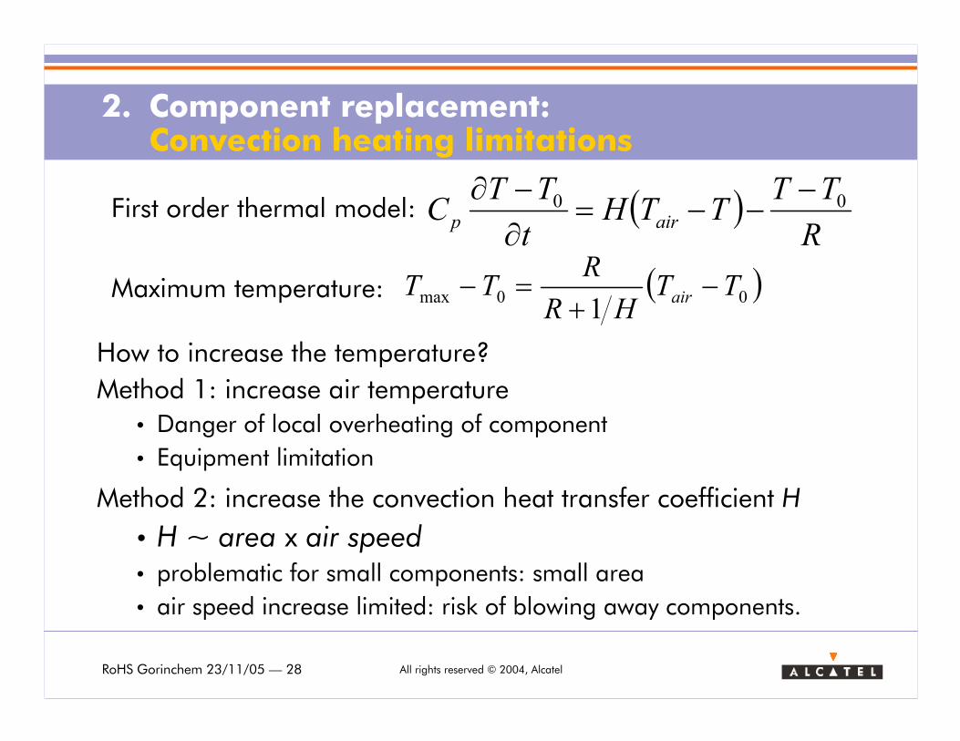
( )00max1
TTHR
RTT air −+=−Maximum temperature:
( )R
TTTTH
t
TTC airp
00 −−−=
∂−∂
First order thermal model:
How to increase the temperature?
Method 1: increase air temperature
• Danger of local overheating of component
• Equipment limitation
Method 2: increase the convection heat transfer coefficient H
• H ~ area x air speed• problematic for small components: small area
• air speed increase limited: risk of blowing away components.
RoHS Gorinchem 23/11/05 — 29 All rights reserved © 2004, Alcatel
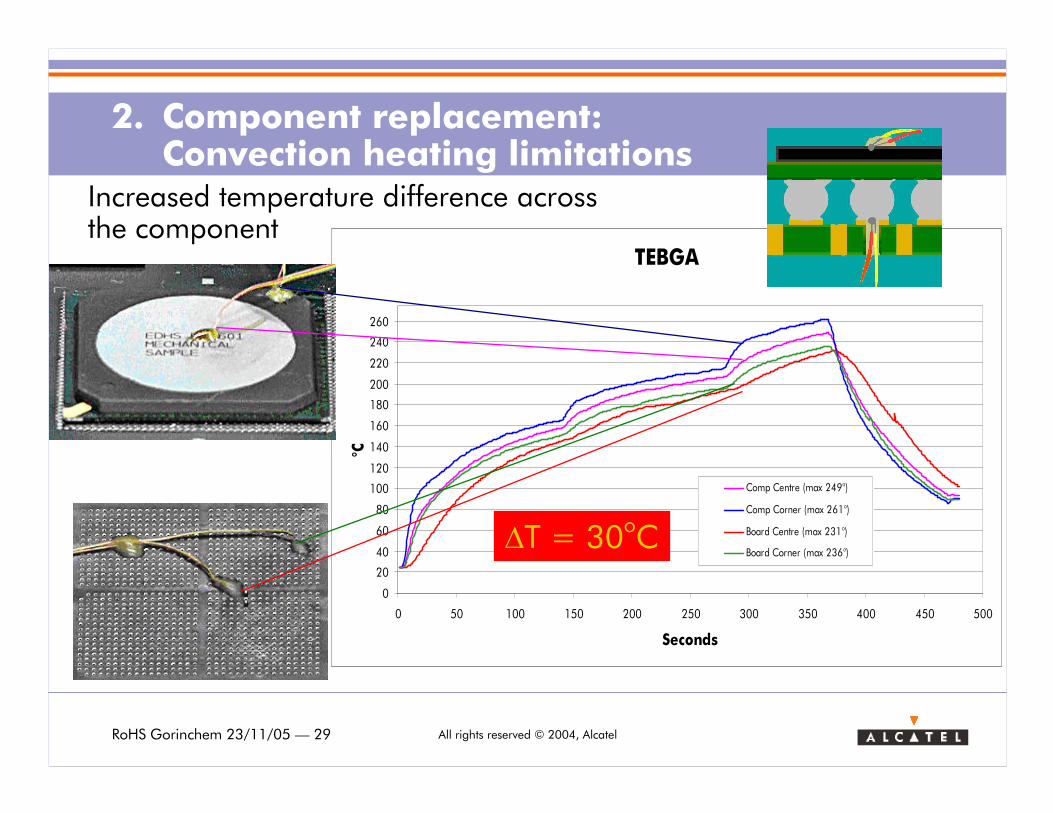
TEBGA
0
20
40
60
80
100
120
140
160
180
200
220
240
260
0 50 100 150 200 250 300 350 400 450 500
Seconds
°C
Comp Centre (max 249°)
Comp Corner (max 261°)
Board Centre (max 231°)
Board Corner (max 236°)
2. Component replacement: Convection heating limitations
Increased temperature difference across the component
∆T = 30oC
RoHS Gorinchem 23/11/05 — 30 All rights reserved © 2004, Alcatel
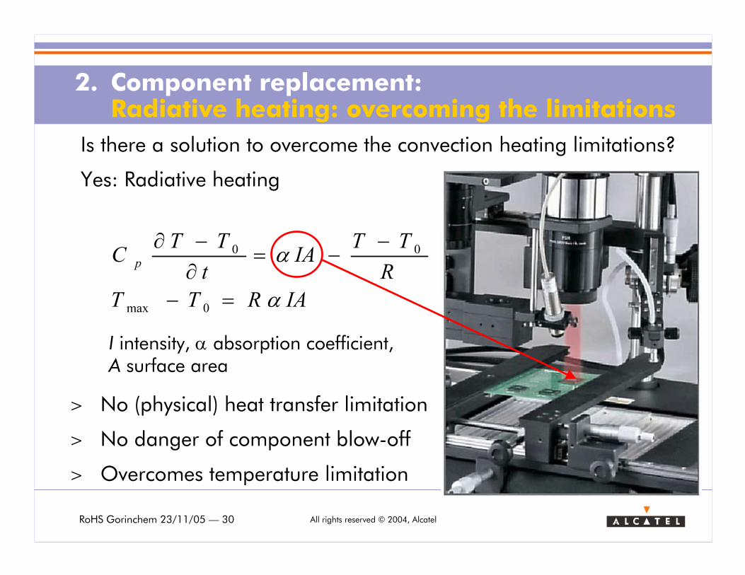
2. Component replacement: Radiative heating: overcoming the limitations
Is there a solution to overcome the convection heating limitations?
Yes: Radiative heating
> No (physical) heat transfer limitation
> No danger of component blow-off
> Overcomes temperature limitation
IARTT
R
TTIA
t
TTC p
α
α
=−
−−=
∂−∂
0max
00
I intensity, α absorption coefficient, A surface area
RoHS Gorinchem 23/11/05 — 31 All rights reserved © 2004, Alcatel
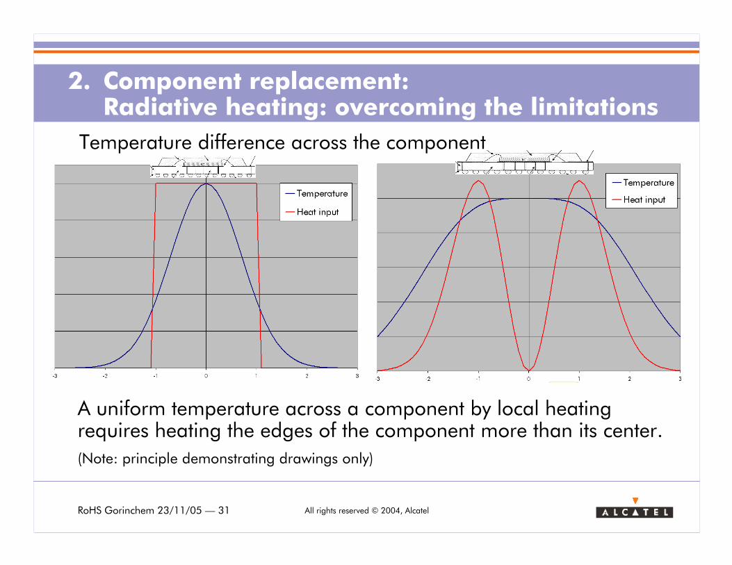
2. Component replacement: Radiative heating: overcoming the limitations
Temperature difference across the component
A uniform temperature across a component by local heating requires heating the edges of the component more than its center.
(Note: principle demonstrating drawings only)
RoHS Gorinchem 23/11/05 — 32 All rights reserved © 2004, Alcatel
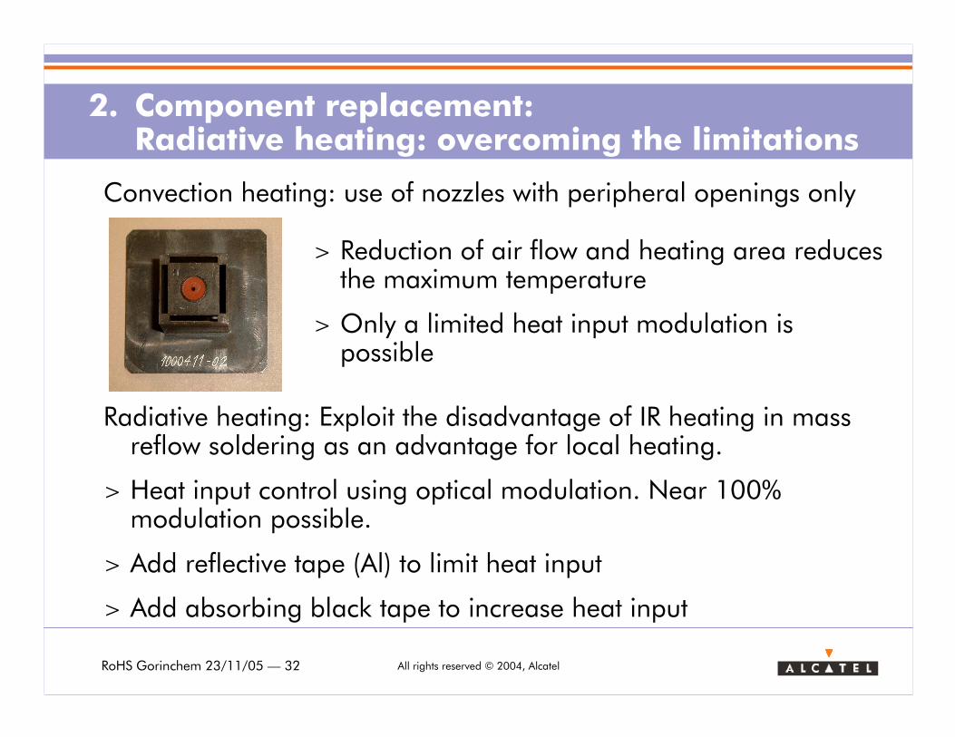
2. Component replacement: Radiative heating: overcoming the limitations
Convection heating: use of nozzles with peripheral openings only
> Reduction of air flow and heating area reduces the maximum temperature
> Only a limited heat input modulation is possible
Radiative heating: Exploit the disadvantage of IR heating in mass reflow soldering as an advantage for local heating.
> Heat input control using optical modulation. Near 100% modulation possible.
> Add reflective tape (Al) to limit heat input
> Add absorbing black tape to increase heat input
RoHS Gorinchem 23/11/05 — 33 All rights reserved © 2004, Alcatel
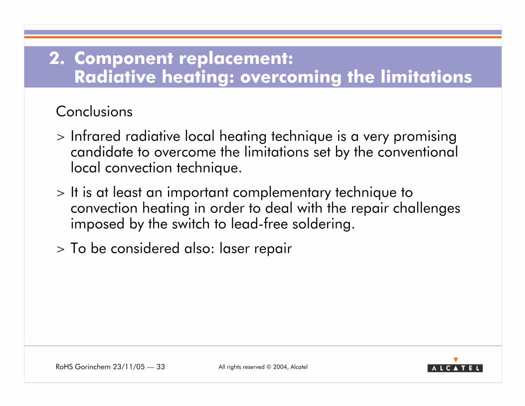
Conclusions
> Infrared radiative local heating technique is a very promising candidate to overcome the limitations set by the conventional local convection technique.
> It is at least an important complementary technique to convection heating in order to deal with the repair challenges imposed by the switch to lead-free soldering.
> To be considered also: laser repair
2. Component replacement: Radiative heating: overcoming the limitations
RoHS Gorinchem 23/11/05 — 34 All rights reserved © 2004, Alcatel
QuitQuit
Qin
Tlucht
QuitQuit
a
r
a/2A
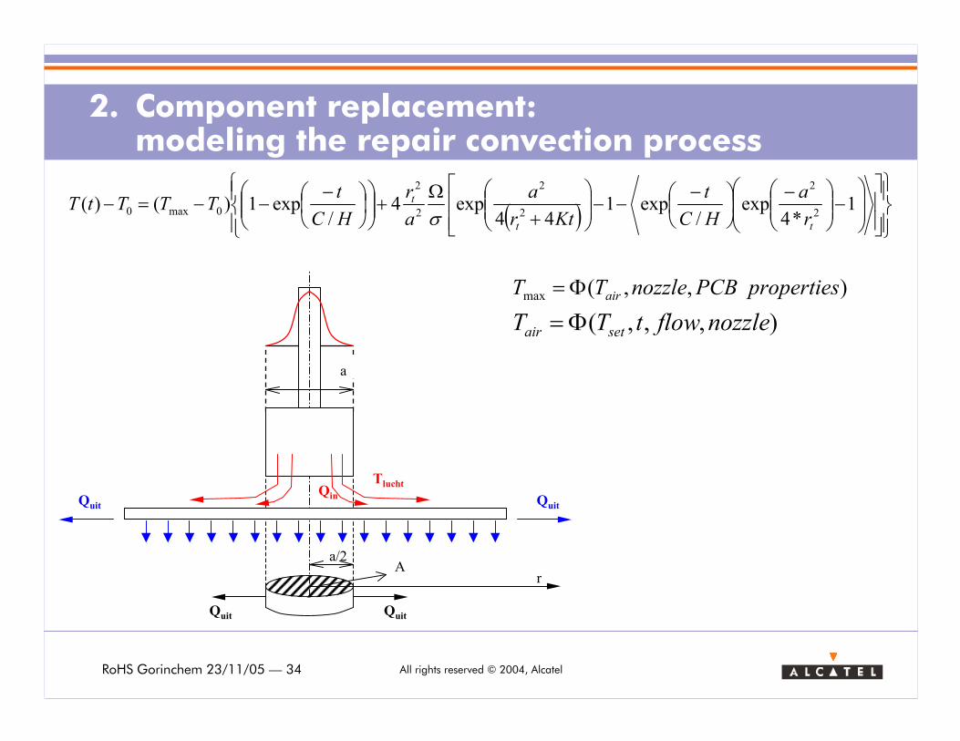
2. Component replacement: modeling the repair convection process
( )
−
−
−−−
+Ω
+
−−−=− 1
*4exp
/exp1
44exp4
/exp1)()(
2
2
2
2
2
2
0max0
tt
t
r
a
HC
t
Ktr
a
a
r
HC
tTTTtT
σ
),,,( nozzleflowtTT setair Φ=
),,(max propertiesPCBnozzleTT airΦ=
RoHS Gorinchem 23/11/05 — 35 All rights reserved © 2004, Alcatel
www.alcatel.be/EMS
Thank you!Thank you!
Alcatel Bell Geel
Bell telephonelaan 3
B-2440 Geel
België
Tel.: +32 14 572 142
Fax: +32 14 572 294


![5TT Mar2016DC1 - belfuse.com · Temperature Derating Curve 0 110 0 70 5 75 Ambient Temperature [ oc] Soldering Parameters Lead-free Wave Soldering Profile Wave Soldering Parameter](https://img.pdfslide.net/doc/110x75/5b5f24757f8b9af90c8d333e/5tt-mar2016dc1-temperature-derating-curve-0-110-0-70-5-75-ambient-temperature.jpg)