Embed Size (px)
Citation preview

Pag. 1 / 12 DMANE01000004-EasyTech_Full IDRO Manual
EasyTech.Full
Temperature Controller for Pellet Stove
Idro
EasyTech.One is a Pellet stoves control system available in Air and Hydro version.
Is characterised by:
Installing and use simplicity
Simple and direct user’s functions
Reliable and flexible functioning software with well-established TiEmme elettronica technology
Advanced functions available for the builder to adapt to different stoves and installations
Product composition:
Control Board with 4 fixing points, solid and sure.
Extractable connectors
Exhausting Temperature Probe until 500 °C
Room Temperature Probe
Boiler Probe
Connection cable Main Board - Control Panel
Control Panel with antistatic cover
Connector RS232 for the Modem/Computer connection
Safety rules
Before working on the system make follow:
The accident prevention and Room prevention rules
The National Institute rules against the work accidents
The legal safety rules
Conformity declaration
Applied rules: EN 60730-1 50081-1 EN 60730-1 A1 50081-2
This manual is done with care and attention, but the information could be incomplete, not comprehensive or could have mistakes. For
this reason the design, the information could be modified without advance notice according to the model.
TiEmme elettronica is not responsible for the incomplete or not correct information
TiEmme elettronica 06055 Marsciano (PG) Italy
Phone:+39.075.874.3905; Fax. +39.075.874.2239 [email protected]
1 Connections
{C0A8C5 9F-6E8F -43c 4-8 453 -65D2 0827 6F40}{ C9 C1B 6A0-3 466 -4D19 -AF 8B -7F AD5F50 AA15}{ C0A8C5 9F-6E8F -43c 4-8 453 -65D2 082 76F4 0}

Pag. 2 / 12 DMANE01000004-EasyTech_Full IDRO Manual
PIN Function Characteristics
1 N
2 L
Voltage Power Supply
230 Vac ± 10% 50/60 Hz
F1= Fuse T5,0 A
3 N
4 L
Combustion Fan Triac Regulation 1A max
5 N
6 L
Pump Triac Regulation 1A max
7 N
8 L
Igniter Resistance Relè 3 A max
9 N
10 L
Auger Pellet Engine Triac Regulation 1A max
11
12
Safety Thermostat Input HV1
Contact ON/OFF Normally closed
To Bypass if not used
13
14
Safety PressureSwitch Input HV2
Contact ON/OFF Normally closed
To Bypass if not used
15
Red+
16 Green —
Exhausting Temperature Probe Thermocouple K: 500 °C Max
17
18
Probe or Room Thermostat / Buffer Probe NTC 10K @25 °C: 80 °C Max
19
20
Boiler Temperature Probe NTC 10K @25 °C: 120 °C Max
21 +5V
22 GND
23 SEG
Encoder Signal Signal TTL 0 / 5 V
24
25
AUX Input: Chrono/Room Thermostat Contact ON/OFF
26 GND
27 SEG
30 +5V
Pressure Water SensorAnalog Signal
28 GND
29 SEG
31 +V
Level Pellet Sensor Signal 0 / 5 V
CN1 Connector to Keyboard Flat Cable
RS23 Connector RS232 Connection to Modem/Computer
2 Control Panel: Use and Functions
2.1 Led / Display
Led
Fix Blinking
L1 Stabilization phase Ignition Start phase
L3 Stove OFF Extinguishing phase
L4 Work phase Modulation/Standby phase
L5 Engine Auger ON
L6 Igniter Resistance ON
L7 Chrono Program enabled
L8 Pump ON
D1 Time
D2 Work Combustion Power set Combustion power change
D3 Boiler Thermostat set Boiler Thermostat change
OFF
P1
P2
P3
P4
D2D3
D1
2.2 Buttons
Tasto Click [P click] Long Pressure [P long]
P1 Display other data Ignition/Extinguishing /Block Reset
P2 Combustion Power Setting Manual Pellet Loading
P3 Thermostat Setting (+) Pellet Loading Correction
P4 Thermostat Setting (-) Combustion Fan Speed Correction
Pag. 3 / 12 DMANE01000004-EasyTech_Full IDRO Manual
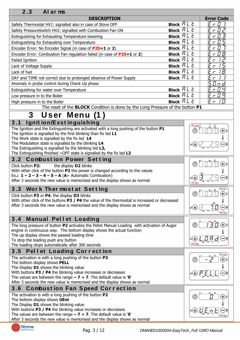
2.3 Alarms
DESCRIPTION Error Code
Safety Thermostat HV1: signalled also in case of Stove OFF Block
Safety PressureSwitch HV2: signalled with Combustion Fan ON Block
Extinguishing for Exhausting Temperature lowering Block
Extinguishing for Exhausting over Temperature Block
Encoder Error: No Encoder Signal (in case of P25=1 or 2) Block
Encoder Error: Combustion Fan regulation failed (in case of P25=1 or 2) Block
Failed Ignition Block
Lack of Voltage Supply Block
Lack of fuel Block
DAY and TIME not correct due to prolonged absence of Power Supply Block
Anomaly in probe control during Check Up phase
Extinguishing for water over Temperature Block
Low pressure in to the Boiler Block
High pressure in to the Boiler Block
The reset of the BLOCK Condition is done by the Long Pressure of the button P1
3 User Menu (1)
3.1 Ignition/Exstinguishing
The Ignition and the Extinguishing are activated with a long pushing of the button P1
The Ignition is signalled by the first blinking than fix led L1
The Work state is signalled by the fix led L4
The Modulation state is signalled by the blinking L4
The Extinguishing is signalled by the blinking led L3,
The Extinguishing finished =OFF state is signalled by the fix led L3
D1
D3D2
P3
P4P2
OFF
P1 Long
3.2 Combustion Power Setting
Click button P2: the display D2 blinks
With other click of the button P2 the power is changed according to the values
Ex.: 1 – 2 – 3 – 4 – 5 – A (A= Automatic Combustion)
After 3 seconds the new value is memorised and the display shows as normal
OFF
D2
P2 Click
3.3 Work Thermostat Setting
Click button P3 or P4: the display D3 blinks
With other click of the buttons P3 / P4 the value of the thermostat is increased or decreased
After 3 seconds the new value is memorised and the display shows as normal
D2
D1
P2
P1
OFF
D3
P4 Click
P3 Click
3.4 Manual Pellet Loading
The long pressure of button P2 activates the Pellet Manual Loading with activation of Auger
engine in continuous way. The bottom display shows the actual function
The up display shows the passed loading time
To stop the loading push any button
The loading stops automatically after 300 seconds
D1
P4
D3D2
P3P1
OFF
P2 Long
3.5 Pellet Loading Correction
The activation is with a long pushing of the button P3
The bottom display shows PELL
The Display D1 shows the blinking value
With buttons P3 / P4 the blinking value increases or decreases
The values are between the range – 7 ÷ 7. The default value is ‘0’
After 3 seconds the new value is memorised and the display shows as normal
D1
P4P2 Long
D3D2
P1 P3 Long
OFF
3.6 Combustion Fan Speed Correction
The activation is with a long pushing of the button P2
The bottom display shows UEnt
The Display D1 shows the blinking value
With buttons P3 / P4 the blinking value increases or decreases
The values are between the range – 7 ÷ 7. The default value is ‘0’
After 3 seconds the new value is memorised and the display shows as normal
P3 Long
D1
P2 Long
D3D2
P1
OFF
P4 Long

Pag. 4 / 12 DMANE01000004-EasyTech_Full IDRO Manual
3.7 Display
The activation is with a click of P1.
tA = Room / Buffer Temperature
tF = Exhausting Temperature
UF= Combustion Fan Speed
[RPM/Volt]]
HF02+Product Code
L6L5
D3
L8L6L5
L4L1
D1
P4 Long
L3
P3 Long
P2 Long
P1 Click
OFF
L5 L6 L8
L4L1
D1
D3
P4 Long
L3
P3 Long
P2 Long
P1 Click
OFF
D3
L8
L4L1
D1
P4 Long
L3
P3 Long
P2 Long
P1 Click
OFF
D3
L8L6L5
L4L1
D1
P4 Long
L3
P3 Long
P2 Long
P1 Click
OFF
Room/Buffer
Temperature
Exhausting
Temperature
Combustion
Fan Speed
Product
Code
3.8 Radio Remote Control
The button 1 activates the Extinguishing ; the button 2 activates the Ignition
The buttons 3 / 4 decrease / increase the Power Combustion
Code Change:
On the Remote Control:
o Open the battery box moving right the cover
o Modify dip-switch’s configuration and close the box
On the Thermoregulator:
Switch OFF the power supply (230 Vac)
Switch ON the Power Supply pressing at the same time one button on the Remote Control
waiting about 5 seconds until an acoustic signal is emitted confirming the code learned
ON
OFF
1
23 4
4 User Menu (2)
Push contemporary the buttons P2 and P4 for three seconds to enter into User Menu (2)
To scroll the Menu push the buttons P3 or P4
To enter in a submenu push the button P2
To modify the blinking value push the button P3 (to increase) or P4 (to decrease)
To exit push the button P1
4.1 Thermostats
4.1.1 Room/Buffer Thermostat
It allows to set the Room Thermostat value P26=0 and A19 =1
Or the Buffer Thermostat P26=1
Room Thermostat Buffer Thermostat
4.2 Chrono
It allows to program the ignitions/extinguishing of the system
4.2.1 Enable
It enables the Programming set.
Push the button P2 to enter
Push the buttons P3/P4 for select
ON= enable programming set OFF=disable programming set
To confirm, push the button P2, or push P1 to esc
4.2.2 Program
It allows to schedule the 3 time bands available for every day of the week
Select
Push the button P2 to enter
Use the buttons P3/P4 to visualize the time bands set:
The upper display visualizes the TIME SET
- - - - if the BAND is disabled
The bottom display visualizes: DAY / BAND / ON/OFF
The long pressure of the button P1 Enables / Disables the selected time band
BAND DISABLED TIME SET
DAY
OFF
BANDON
BAND
DAY
PROGRAMMING AROUND MIDNIGHT
Set the hour of On for the previous day to the wanted value: Example 20.30
Set the hour of OFF for the previous day at: 23:59
Set the hour of On for the next day at 00:00
Set the hour of OFF for the next day to the wanted value: Example 6:30
The system will turn on Tuesday, at 20.30, and will turn off on Wednesday, at 6.30.
4.3 Time and Date
It allows to set the current day and time
4.4 Radio Remote Control
ON= Enabled OFF= Disabled
Pag. 5 / 12 DMANE01000004-EasyTech_Full IDRO Manual
5 Installer’s Menu
Push contemporary the buttons P2+P4 and choose TPAr to enter in the installer menu protected by
password
TPAr
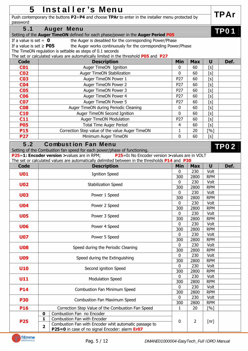
5.1 Auger Menu
Setting of the Auger TimeON defined for each phase/power in the Auger Period P05
TP01
If a value is set = 0 the Auger is desabled for the corresponding Power/Phase
If a value is set ≥ P05 the Auger works continuously for the corresponding Power/Phase
The TimeON regulation is settable as steps of 0.1 seconds
The set or calculated values are automatically limited in the threshold P05 and P27
Code Description Min Max U Def.
C01Auger TimeON Ignition 0 60 [s]
C02Auger TimeON Stabilization 0 60 [s]
C03Auger TimeON Power 1 P27 60 [s]
C04Auger TimeON Power 2 P27 60 [s]
C05Auger TimeON Power 3 P27 60 [s]
C06Auger TimeON Power 4 P27 60 [s]
C07Auger TimeON Power 5 P27 60 [s]
C08Auger TimeON during Periodic Cleaning 0 60 [s]
C10Auger TimeON Second Ignition 0 60 [s]
C11Auger TimeON Modulation P27 60 [s]
P05Total Time Auger Period 4 60 [s]
P15Correction Step value of the value Auger TimeON 1 20 [%]
P27Minimum Auger TimeON 0 60 [s]
5.2 Combustion Fan Menu
Setting of the Combustion fan speed for each power/phase of functioning.
TP02
P25=1: Encoder version >values are in RPM; P25=0: No Encoder version >values are in VOLT
The set or calculated values are automatically delimited between in the thresholds P14 and P30
Code Description Min Max U Def.
0 230 Volt
U01Ignition Speed
300 2800 RPM
0 230 Volt
U02Stabilization Speed
300 2800 RPM
0 230 Volt
U03Power 1 Speed
300 2800 RPM
0 230 Volt
U04Power 2 Speed
300 2800 RPM
0 230 Volt
U05Power 3 Speed
300 2800 RPM
0 230 Volt
U06Power 4 Speed
300 2800 RPM
0 230 Volt
U07Power 5 Speed
300 2800 RPM
0 230 Volt
U08Speed during the Periodic Cleaning
300 2800 RPM
0 230 Volt
U09Speed during the Extinguishing
300 2800 RPM
0 230 Volt
U10Second ignition Speed
300 2800 RPM
0 230 Volt
U11Modulation Speed
300 2800 RPM
0 230 Volt
P14Combustion Fan Minimum Speed
300 2800 RPM
0 230 Volt
P30Combustion Fan Maximum Speed
300 2800 RPM
P16Correction Step Value of the Combustion Fan Speed 1 20 [%]
0 Combustion Fan no Encoder
1 Combustion Fan with Encoder
P25
2
Combustion Fan with Encoder whit automatic passage to
P25=0 in case of no signal Encoder: alarm Er07
0 2 [nr]

Pag. 6 / 12 DMANE01000004-EasyTech_Full IDRO Manual
5.3 Thermostats’ Menu
TP04
Code Description Probe Min Max U Def.
Th01Stove OFF Thermostat Exhausting 5 900 [°C]
Th02Deactivation Igniter Resistance Thermostat Exhausting 5 900 [°C]
Th03Pre-Extinguishing Thermostat for no flame Exhausting 5 900 [°C]
Th06Thermostat to go in Stabilization from Variable phase Exhausting 5 900 [°C]
Th07Modulation Thermostat for Exhausting OverTemperature Exhausting 5 900 [°C]
Th08Safety Thermostat for Exhausting OverTemperature Exhausting 5 900 [°C]
Th09Ignition Bypass Thermostat Exhausting 5 900 [°C]
Th18
Antifreeze Thermostat Boiler5 10 [°C]
Th19
Enable Pump Thermostat Boiler30 85 [°C]
Ih19
Enable Pump Thermostat Hysteresis Boiler1 20 [°C]
Th21
Discharge Thermostat (Unblock Pump) Boiler30 85 [°C]
Ih24
Boiler Thermostat Hysteresis Boiler1 20 [°C]
Th25
Boiler Safety Thermostat Boiler80 99 [°C]
Th26
Minimum Range of Boiler Thermostat Boiler30 60 [°C]
Th27
Maximum Range of Boiler Thermostat Boiler60 95 [°C]
Th28Stove OFF Thermostat in Standby Exhausting 5 900 [°C]
Ih33
Room Thermostat HysteresisRoom 0 10 [°C]
Th47
[Boiler Probe – Buffer Probe] Differential ThermostatBuffer 1 30 [°C]
Ih47
Differential Thermostat HysteresisBuffer 1 5 [°C]
Ih48
Buffer Thermostat HysteresisBuffer 1 20 [°C]
d01Increasing Delta Temperature in Stabilization Exhausting 0 100 [°C]
d08
Delta Water Temperature in the boiler for Combustion
Power Automatic Regulation [A]
Boiler 1 30 [°C]
d23
Increasing Delta Water Temperature over the Boiler
Thermostat to go from Modulation to Standby, if
A13=2, at the end of T43
Boiler 0 50 [°C]
SP01Minimum threshold of water pressure in the boiler 50 3000 [°C]
SP08Maximum threshold of water pressure in the boiler 50 3000 [°C]
5.4 Timer Menu
TP05
Code Description Min Max U Def.
T01Ignition: Cleaning Time 0 900 [s]
T02Ignition: Igniter Resistance Pre-heating Time 0 900 [s]
T03Ignition: Pre-Load Time 0 900 [s]
T04Ignition: Fix Time 1 3600 [s]
T05Ignition: Variable Time 1 3600 [s]
T06Ignition: Stabilization Time 0 900 [s]
T07Interval Periodic Cleaning Repetion 15 600 [min]
T08Periodic Cleaning Time 0 900 [s]
T09Delay time HV1 Safety intervention 1 900 [s]
T10Delay time HV2 Safety intervention (Pressureswitch) 1 900 [s]
T11Delay time for Standby Exit 0 900 [s]
T13Minimum Period Time of Extinguishing 0 900 [s]
T14Waiting time Pre-Extinguishing for no flame 0
900[s]
T15Waiting time Pre-Extinguishing in Safety 0
900[s]
T16Final Cleaning Time 0
900[s]
T17Delay time Combustion Power Change 0
900[s]
T18Delay time Combustion Power Change in exit from Ignition 0 900 [s]
T22Delay time for Standby Input 0 900 [s]
T24Length signalling of fuel lack 0 3600 [s]
T41Work time of Pump 0 3600 [s]
T42Maximum time of inactivity of Pump 1 9600 [ore]
T43
Time, after which the stove goes from Modulation to Standby if
Water Temperature> [Boiler Thermostat t+d23] and A13= 1
0 9600 [s]

Pag. 7 / 12 DMANE01000004-EasyTech_Full IDRO Manual
5.5 Enable’s Menu
TP08
Code Description Min Max U Def.
0 Reached the Room Thermostat the stove goes in Extinguishing
1 Reached the Room Thermostat the stove goes in Modulation
2 Reached the Room Thermostat the stove goes in Standby
A01
For P26=0
3
Reached the Room Thermostat the system blocks the Pump
until water temperature < Th21
0 3 [nr]
0 In Modulation the system uses Power 1: C03,U03
A06
1 In Modulation the system uses Modulation Power: C11,U11
0 1 [nr]
0 The input AUX is used for ON/OFF functioning
1 The input AUX is used for Modulation/Normal functioning
2 The input AUX is used for Standby/Normal functioningA07
3
The input AUX is used to block the Pump until water
temperature < Th21 ( P26=0 )
0 3 [nr]
0 Reached the Boiler Thermostat the stove goes in Modulation
A13
1
Reached the Boiler Thermostat the stove goes in Modulation,
then if d23 is satisfied and T43 is finished it goes in Standby
0 1 [nr]
0 Error Sensor Pressure disabled
A14
1 Error Sensor Pressure enabled
0 1 [nr]
0 Room Thermostat ON/OFF selected
A19
1 Room Probe selected
0 1 [nr]
0 The immediate Exit from StandBy is allowed
A26
1
Exit from Standby is allowed
>after the timer T13 and
> if the Exhausting Temperature<Th28
0 1 [nr]
0 Auger brake not activated
A28
1 Auger brake activated
0 1 [nr]
0 Modem Management disabled
A50
1 Modem Management enabled
0 1 [nr]
P02Maximum number ignition attempts 1 5 [nr]
P03Work Combustion Powers’ number 1 5 [nr]
P09Pellet Sensor configuration: 0=N.C. 1=N.O. 0 1 [nr]
P20Configuration of Pressure Boiler Water Sensor (see section 7.9) 0 2 [nr]
P26Plumbing system management (see section 7.10) 0 1 [nr]
5.6 Outputs Menu Test
TP12
It allows the test of the single management outputs with the connected devices. The function is available in OFF state.
Code Description Min Max U
To01Auger Test Off On -
0 230 [Volt]
To03Combustion Fan Test
300 2800 [RPM]
During the Combustion Fan Test, the upper display shows the setted value [Volt] o [RPM], the under display shows the
RPM of the fan detected by the encoder if is present: so it is possible to create a conversion table [RPM] / [Volt] to use
for the passage from encoder Mode P25=1 to not encoder Mode P25=0 in case of encoder breakage
To04Igniter Resistance Test Off On -
To05Pump Test Off On -
5.7 Extinguishing Thermostats Menu
TP13
Settings for each Combustion Phase/Power of the Exhausting Temperature under which, after the Pre-Extinguishing time
T14, the stove goes in Extinguishing for no flame. These values occur with the Th03 Thermostat
Code Description Probe Min Max U Def.
Th35Power 1 Exhausting 5 900 [°C]
Th36Power 2 Exhausting 5 900 [°C]
Th37Power 3 Exhausting 5 900 [°C]
Th38Power 4 Exhausting 5 900 [°C]
Th39Power 5 Exhausting 5 900 [°C]
Th40Modulation Power Exhausting 5 900 [°C]
Th43Power 1 Exhausting 5 900 [°C]
Pag. 8 / 12 DMANE01000004-EasyTech_Full IDRO Manual
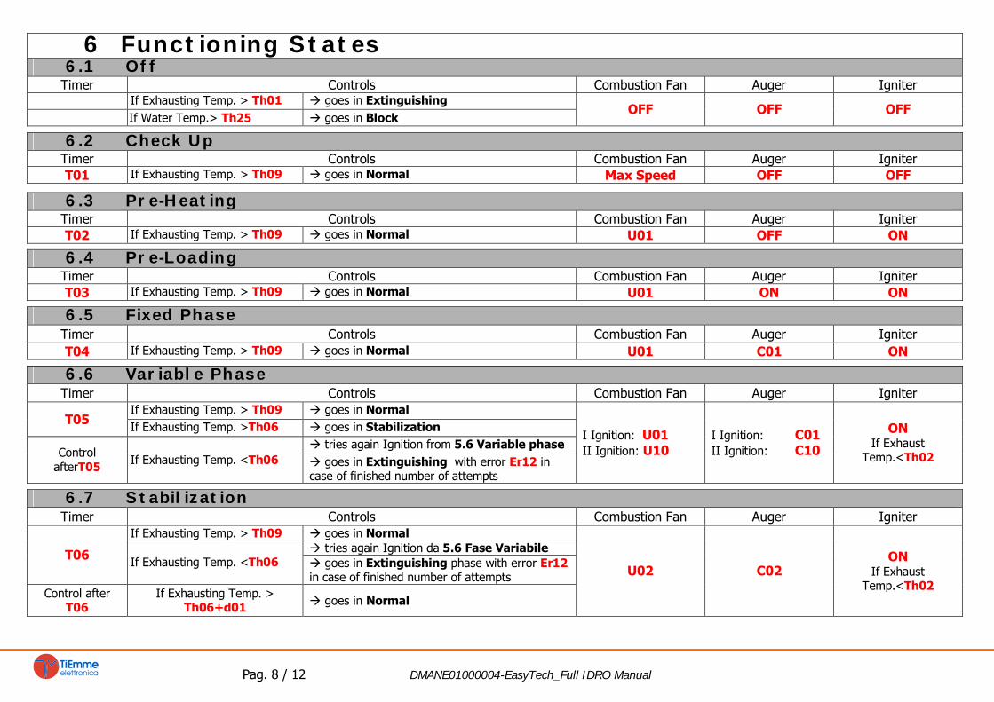
6 Functioning States
6.1 Off
Timer Controls Combustion Fan Auger Igniter
If Exhausting Temp. > Th01 goes in Extinguishing
If Water Temp.> Th25 goes in Block
OFF OFF OFF
6.2 Check Up
Timer Controls Combustion Fan Auger Igniter
T01
If Exhausting Temp. > Th09 goes in Normal
Max Speed OFF OFF
6.3 Pre-Heating
Timer Controls Combustion Fan Auger Igniter
T02
If Exhausting Temp. > Th09 goes in Normal
U01 OFF ON
6.4 Pre-Loading
Timer Controls Combustion Fan Auger Igniter
T03
If Exhausting Temp. > Th09 goes in Normal
U01 ON ON
6.5 Fixed Phase
Timer Controls Combustion Fan Auger Igniter
T04
If Exhausting Temp. > Th09 goes in Normal
U01 C01 ON
6.6 Variable Phase
Timer Controls Combustion Fan Auger Igniter
If Exhausting Temp. > Th09 goes in Normal
T05
If Exhausting Temp. >Th06 goes in Stabilization
tries again Ignition from 5.6 Variable phase
Control
afterT05
If Exhausting Temp. <Th06
goes in Extinguishing with error Er12 in
case of finished number of attempts
I Ignition: U01
II Ignition: U10
I Ignition: C01
II Ignition: C10
ON
If Exhaust
Temp.<Th02
6.7 Stabilization
Timer Controls Combustion Fan Auger Igniter
If Exhausting Temp. > Th09 goes in Normal
tries again Ignition da 5.6 Fase Variabile
T06
If Exhausting Temp. <Th06
goes in Extinguishing phase with error Er12
in case of finished number of attempts
Control after
T06
If Exhausting Temp. >
Th06+d01
goes in Normal
U02 C02
ON
If Exhaust
Temp.<Th02

Pag. 9 / 12 DMANE01000004-EasyTech_Full IDRO Manual
6.8 Recover Ignition
The system goes in Recover Ignition:
After a lack Voltage Supply when the stove were in ON, when the voltage return if the Exhausting Temperature > Th06+D01
Pushing the button ON/OFF when the system is in Extinguishing
Timer Controls Combustion Fan Auger Igniter
If Exhausting Temp.>Th01 Thermostat waits and continues extinguishing
U09
T16
If Exhausting Temp.<Th01 Thermostat starts Timer T16 of final cleaning
Max Speed
OFF OFF
Control after T16 If Exhausting Temp.<Th01 Thermostat goes in Check Up
6.9 Normal
Parameters Controls Combustion Fan Auger Igniter
T14
If Exhausting Temp. < Th03 Thermostat or
If Exhausting Temp. < Extinguishing Thermostat for
the used power
starts Timer T14 of
pre-extinguishing
waiting
Control after
T14
Goes in Extinguishing with error Er03
If Exhausting Temp. > Th07 Thermostat
If Water Temp.> Boiler Thermostat
A01=1If Room Temperature > Room Thermostat
A07=1If Input AUX open
goes in Modulation
A01=2If Room Temperature > Room Thermostat
A07=2If Input AUX open
Buffer Temperature > Buffer Thermostat and P26= 1
goes in Standby
goes in Standby
T15
If Exhausting Temp. > Th08 Thermostat
If Water Temp.> Th25 Thermostat
starts Timer T15
Control after
T15
Goes in Extinguishing phase for Security
User’s Power User’s Power OFF

Pag. 10 / 12 DMANE01000004-EasyTech_Full IDRO Manual
6.10 Modulation
Parameters Controls Combustion Fan Auger Igniter
A06=1 A06=0 A06=1 A06=0
T14
If Exhausting Temp. < Th03 Thermostat or
If Exhausting Temp. < Extinguishing Thermostat for
the used power
starts Timer T14 of
pre-extinguishing
waiting
Control after
T14
Goes in Extinguishing with error Er03
T15
If Exhausting Temp. > Th08 Thermostat
If Water Temp.> Th25 Thermostat
starts Timer T15
Control after
T15
Goes in Extinguishing with error Er05
A13=1
If for time T43
Water Temp.> Boiler Thermostat+d23
goes in Standby
U11 U03 C11 C03
OFF
6.11 Standby
Parameters Controls Combustion Fan Auger Igniter
T13
Extinguishing
If Exhausting Temp. > Th28 Thermostat starts Timer T13
Control after T13If Exhausting Temp. > Th28 Thermostat wait
U09
T16
Final Cleaning
If Exhausting Temp. < Th28 Thermostat starts T16Max Speed
Control after
T16
Goes in Standby OFFOFF
OFF OFF
6.12 Extinguishing
Parameters Controls Combustion Fan Auger Igniter
T13
Extinguishing
If Exhausting Temp. > Th01 Thermostat starts Timer T13
Control after
T13
If Exhausting Temp. > Th01 Thermostat wait
U09
T16
Final Cleaning
If Exhausting Temp. < Th01 Thermostat starts Timer T16Max Speed
Goes in OFF without errorsControl after
T16
Goes in Block with possible errors
OFF
OFF OFF
6.13 Block
Controls Combustion Fan Auger Igniter
To exit: Push for 3 seconds button P1
With no more block conditions Goes in OFF
OFF OFF OFF

Pag.11 / 12 DMANE01000004- Manual EasyTech_Full IDRO
7 Functions
7.1 Modem management
The system manages a modem module (given on demand) for the dialogue with the stove through SMS to operate the
Ignition, Extinguishing, State’s request and have information about the Block/Alarms conditions. The Modem is connected
to the Control Board’s port RS232 with cables and connectors given; it is supplied with a AC/DC Power Supply unit.
Use a SIM card in the Modem enabled to the traffic GSM data
Desable the PIN request from the SIM
The Modem management is activated with the parameter A50 =1
The insertion and removal of the SIM card MUST be done with the Modem NOT supplied
Scheda EasyTech
EasyTech Board
CN
3
CN4
RS
23
2
CAB_2
PW_1
Power Supply
Alimentatore
23
0V
ac
Modem
The user can send an SMS to the Modem’s SIM with a command word written both capital and small
Start
To start Ignition from stove OFF.
The Modem sends back a message to the number from which it received the command with a
status and a possible alarm error code.
Stop
To start Extinguishing from stove ON.
The Modem sends back a message to the number from which it received the command with a
status and a possible alarm error code.
Status
To ask the stove’s State.
The Modem sends back a message to the number from which it received the command with a
status and a possible alarm error code.
Learn
To Learn the number to send an SMS in case of Block.
If there is a Block condition, the Modem automatically sends a message to the learnt number with
the stove’s state and the alarm error code.
7.2 Supply Voltage Lack Management
In case of Supply Voltage lack, the system saves the most important functioning data.
With the return of the Supply Voltage, the system evaluates the saved data and:
If the stove were ON and the Exhausting Temperature more than Th06+d01 the system goes in Recover Ignition.
Pushing the button P1 it is possible the sudden new system’s Ignition.
If the stove were ON but the Exhausting Temperature is less than Th06+d01 the system goes in Extinguishing
with error Er15.
If the stove were OFF, or in Extinguishing or Block, the system returns in the previous state.
In case of prolonged absence of Supply Voltage (about one week) the systems goes in BLOCK with error
message Er11 to indicate not correct DAY and TIME value.
After the reset by the button P1, the Time value blinks signalling the need to set the right Time
7.3 Combustion power change delay Management
When the system exits from the Ignition and goes in Normal, the Combustion Power, starting from the Combustion
Power 1, reaches the target one increasing the value with the delay time as the timer T18.
The other manual or automatic power changes are managed and actuated with the delay time as timer T17.
7.4 Brazier’s periodic cleaning
When the stove is activated, the system automatically starts the brazier’s periodic clearing.
With intervals as Timer T07 (minutes) the Combustion is taken to Periodic Cleaning Power according to parameters C08
and U08 for the Timer T08 (seconds).
CN4
CN3
Antenna
Below
Above
SIM Card
Pag.12 / 12 DMANE01000004- Manual EasyTech_Full IDRO
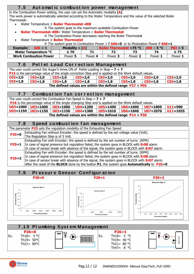
7.5 Automatic combustion power management
In the Combustion Power setting, the user can set the Automatic modality [A]
The work power is automatically selected according to the Water Temperature and the value of the selected Boiler
Thermostat:
Water Temperature ≤ Boiler Thermostat–d08
The system goes to the maximum available Combustion Power
Boiler Thermostat–d08< Water Temperature < Boiler Thermostat
The Combustion Power decreases reaching the Boiler Thermostat
Water Temperature ≥ Boiler Thermostat
The system goes to Combustion Power 1 if A06=0 or to Modulation Power if A06=1
Example: A06 = 1 Modality = [A] Boiler Thermostat =75 °C d08 = 5 °C P03 = 5
Water Temperature °C ≤ 70 71 72 73 74 ≥ 75
Work Combustion Power Power 5 Power 4 Power 3 Power 2 Power 1 Power 1
7.6 Pellet Load Correction Management
The user could correct the Auger’s times ON of Pellet Loading in Step – 7 ÷ 7
P15 is the percentage value of the single correction Step and is applied on the Work default values.
C03=2,0 C03=2,0 C03=2,0 C03=2,0 C03=2,0 C03=2,0 C03=2,0C03=2,0
C03=1,8C03=1,8 C03=1,8 C03=1,8 C03=1,8 C03=1,8 C03=1,8 C03=1,8
The defined values are within the defined range P27 ÷ P05
7.7 Combustion fan correction management
The user could correct the Combustion Fan Speed in Step – 7 ÷ 7
P16 is the percentage value of the single changing Step and is applied on the Work default values.
U03=1000 U03=1000 U04=1200 U05=1400 U06=1600 U07=1800 U11=900U03=1000
U03=1150U03=1150 U03=1150 U04=1380 U05=1610 U06=1840 U07=2070 U11=1035
The defined values are within the defined range P14 ÷ P30
7.8 Speed combustion fan management
The parameter P25 sets the regulation modality of the Exhausting Fan Speed
P25=0
Exhausting Fan without Encoder: the speed is defined by the set voltage value [Volt].
The Regulation Step is of 5 Volt.
P25=1
Exhausting Fan with Encoder: the speed is defined by the set number of turns [RPM]
In case of signal presence but regulation failed, the system goes in BLOCK with Er08 alarm
In case of sensor break with absence of the signal, the system goes in BLOCK with Er07 alarm
P25=2
Exhausting Fan with Encoder: the speed is defined by the set number of turns [RPM]
In case of signal presence but regulation failed, the system goes in BLOCK with Er08 alarm
In case of sensor break with absence of the signal, the system goes in BLOCK with Er07 alarm.
After the reset of the BLOCK done by the button P1, the system goes Automatically to P25=0
7.9 Pressure Sensor Configuration
P20=0
Sensore tipo A
0
0,5
1
1,5
2
2,5
3
0 500 1000 1500 2000 2500 3000
Pressione (mbar)
Te
ns
io
ne
(V
olt)
P20=1
Sensore tipo B
0
0,5
1
1,5
2
2,5
0 1000 2000 3000 4000
Pressione (mbar)
Te
ns
io
ne
(V
olt)
P20=2
Sensore tipo C
0
0,5
1
1,5
2
2,5
3
3,5
0 500 1000 1500 2000 2500 3000 3500 4000
Pressione (mbar)
Te
ns
io
ne
(V
olt)
7.10 Plumbing System Management
P26=0
Ex. Th18= 5 °C
Th19= 50°C
Th21= 80°C
S1
P26=1
Ex. Th18= 5 °C
Th19= 40 °C
Th21= 80 °C
Th47= 8 °C
S1
BU
FF
ER
S2