Embed Size (px)
Citation preview
Transport Safety Agency TRAFI/31298/03.04.01.00/2010
MARITIME SAFETY REGULATION
Date of issue: 23 Nov. 2010 Period of validity: 1 Dec. 2010 – until further notice Based on: Act on the Ice Classes of Ships and Icebreaker Assistance (1121/2005), section 4.1 Repeals: -
Transport Safety Agency, P.O. Box 320, FI-00101 HELSINKI, FINLAND, tel. +358 20 618 500, fax +358 20 618 5095, www.trafi.fi
ICE CLASS REGULATIONS AND THE APPLICATION THEREOF
1 Purpose of the regulations The Finnish Transport Safety Agency issues the attached Ice Class Regulations, 2010, which constitute the more detailed regulations on the requirements concern-ing the structure, engine output and other ice navigation properties of ships be-longing to different ice classes, on the methods for determining ice classes, and on differences between ice classes, referred to in section 4.1 of the Act on the Ice Classes of Ships and Icebreaker Assistance (1121/2005).
2 Application of the 2010 Ice Class Regulations The Ice Class Regulations of 2010 apply to ships contracted for construction on 1 January 2012 or thereafter. As from 1 December 2010, the Ice Class Regulations of 2010 may also be applied to ships contracted for construction on 1 December 2010 or thereafter. The provisions in section 1 (General) and 2 (Ice Class Draught) in the 2010 Ice Class Regulations apply to all ships irrespective of their year of build.
3 Application of the 2008 Ice Class Regulations
The Ice Class Regulations of 2008 (8.12.2008 No. 2530/30/2008), issued by the Finnish Maritime Administration, apply to ships contracted for construction on 1 January 2010 or thereafter but before 1 January 2012.
4 Application of the 2002 Ice Class Regulations The Ice Class Regulations of 2002 (20.9.2002 No. 5/30/2002) of the Finnish Mari-time Administration, as amended, apply to ships the keels of which have been laid or which have been at a similar stage of construction on 1 September 2003 or thereafter, and which have been contracted for construction before 1 January 2010.

2
5 Application of the 1985 Ice Class Rules The Board of Navigation Rules for Assigning Ships Separate Ice-Due Classes, 1985, (2.9.1985 No. 2575/85/307), as amended, apply to ships the keels of which have been laid or which have been at a similar stage of construction on 1 November 1986 or thereafter but before 1 September 2003. On the owner’s request, the re-quirements of the 2008 Ice Class Regulations may, however, be applied to the en-gine output of such ships. In addition, ships of ice class IA Super or IA the keels of which have been laid or which have been at a similar stage of construction before 1 September 2003 shall comply with the requirements in section 3.2.2 of the Ice Class Regulations of 2010 not later than January 1 in the year when twenty years have elapsed since the year the ship was delivered, whichever occurs the latest.
6 Application of the 1971 Ice Class Rules The requirements of Annex 1 or, depending on the ship’s age, section 10 of the Board of Navigation Rules for Assigning Ships Separate Ice-Due Classes of 1971 (6.4.1971 No. 1260/71/307), as amended, apply to ships the keels of which have been laid or which have been at a similar stage of construction before 1 November 1986. On the owner’s request, the requirements of the 1985 Ice Class Rules or the 2008 Ice Class Regulations may be applied to the engine output of such ships. In addition, ships of ice class IA Super or IA the keels of which have been laid or which have been at a similar stage of construction before 1 September 2003 shall comply with the requirements in section 3.2.2 of the Ice Class Regulations of 2010 not later than 1 January in the year when twenty years have elapsed since the year the ship was delivered, whichever occurs the latest.
7 Entry into force
These regulations and the attached Ice Class Regulations of 2010 enter into force on 1 December 2010.
Tuomas Routa Director General, Regulation and Supervision
Jorma Kämäräinen Senior Maritime Inspector
1
ICE CLASS REGULATIONS 2010
“FINNISH-SWEDISH ICE CLASS RULES 2010”
23.11.2010 TRAFI/31298/03.04.01.00/2010 _________________
TABLE OF CONTENTS 1 GENERAL 4
1.1 Ice classes 4
2 ICE CLASS DRAUGHT 4 2.1 Upper and lower ice waterlines 4 2.2 Maximum and minimum draught fore and aft 4
3 ENGINE OUTPUT 5 3.1 Definition of engine output 5 3.2 Required engine output for ice classes IA Super, IA, IB and IC 5
3.2.1 Definitions 5 3.2.2 New ships 6 3.2.3 Existing ships of ice class IB or IC 8 3.2.4 Existing ships of ice class IA Super or IA 8 3.2.5 Other methods of determining Ke or RCH 9
4 HULL STRUCTURAL DESIGN 9 4.1 General 9
4.1.1 Hull regions 11 4.2 Ice load 11
4.2.1 Height of the ice load area 11 4.2.2 Ice pressure 12
4.3 Shell plating 13 4.3.1 Vertical extension of ice strengthening for plating (ice belt) 13 4.3.2 Plate thickness in the ice belt 14
4.4 Frames 14 4.4.1 Vertical extension of ice strengthening for framing 14 4.4.2 Transverse frames 15
4.4.2.1 Section modulus and shear area 15 4.4.2.2 Upper end of transverse framing 16 4.4.2.3 Lower end of transverse framing 16
4.4.3 Longitudinal frames 17 4.4.3.1 Frames with and without brackets 17
4.4.4 General on framing 18 4.4.4.1 The attachment of frames to supporting structures 18 4.4.4.2 Support of frames against tripping for ice class IA Super, for ice class IA in
the forward and midbody regions and for ice classes IB and IC in the bow region of the ice-strengthened area 18
2
4.5 Ice stringers 18
4.5.1 Stringers within the ice belt 18 4.5.2 Stringers outside the ice belt 19 4.5.3 Deck strips 20
4.6 Web frames 20 4.6.1 Ice load 20 4.6.2 Section modulus and shear area 20
4.7 Stem 21 4.8 Stern 22
5 RUDDER AND STEERING ARRANGEMENTS 23
6 PROPULSION MACHINERY 23
6.1 Scope 23 6.2 Definitions 23 6.3 Design ice conditions 27 6.4 Materials 28
6.4.1 Materials exposed to sea water 28 6.4.2 Materials exposed to sea water temperature 28
6.5 Design loads 28 6.5.1 Design loads on propeller blades 28
6.5.1.1 Maximum backward blade force Fb for open propellers 28 6.5.1.2 Maximum forward blade force Ff for open propellers 29 6.5.1.3 Loaded area on the blade for open propellers 29 6.5.1.4 Maximum backward blade ice force Fb for ducted propellers 31 6.5.1.5 Maximum forward blade ice force Ff for ducted propellers 31 6.5.1.6 Loaded area on the blade for ducted propellers 31 6.5.1.7 Maximum blade spindle torque Qsmax for open and ducted propellers 32 6.5.1.8 Load distribution for blade loads 32 6.5.1.9 Number of ice loads 33
6.5.2 Axial design loads for open and ducted propellers 34 6.5.2.1 Maximum ice thrust on propeller Tf and Tb for open and ducted propellers 34 6.5.2.2 Design thrust along the propulsion shaft line for open and ducted propellers 34
6.5.3 Torsional design loads 35 6.5.3.1 Design ice torque on propeller Qmax for open propellers 35 6.5.3.2 Design ice torque on propeller Qmax for ducted propellers 35 6.5.3.3 Ice torque excitation for open and ducted propellers 36 6.5.3.4 Design torque along propeller shaft line 37
6.5.4 Blade failure load 37 6.6 Design 38
6.6.1 Design principle 38 6.6.2 Propeller blade 38
6.6.2.1 Calculation of blade stresses 38 6.6.2.2 Acceptability criterion 38 6.6.2.3 Fatigue design of propeller blade 39 6.6.2.4 Acceptability criterion for fatigue 41
6.6.3 Propeller bossing and CP mechanism 42 6.6.4 Propulsion shaft line 42
6.6.4.1 Shafts and shafting components 42 6.6.5 Azimuthing main propulsors 42 6.6.6 Vibrations 43
6.7 Alternative design methods 43
3
6.7.1 Scope 43 6.7.2 Loading 43 6.7.3 Design levels 43
7 MISCELLANEOUS MACHINERY REQUIREMENTS 43
7.1 Starting arrangements 43 7.2 Sea inlet and cooling water systems 44
Annex I The validity of the powering requirement in section 3.2.2 for ice classes IA Super,
IA, IB and IC, and verification of calculated powering requirements 45 Annex II Required engine output for a ship of ice class IB or IC the keel of which has been
laid or which has been at a similar stage of construction before 1 September 2003 47 Annex III Ice class draught marking 48
4
1 GENERAL 1.1 Ice classes Under section 3 of the Act on the Ice Classes of Ships and Icebreaker Assistance (1121/2005) ships are assigned to ice classes as follows:
1. ice class IA Super; ships with such structure, engine output and other properties that they are normally capable of navigating in difficult ice conditions without the assistance of icebreakers;
2. ice class IA; ships with such structure, engine output and other properties that they are capable of navigating in difficult ice conditions, with the assistance of icebreakers when necessary;
3. ice class IB; ships with such structure, engine output and other properties that they are capable of navigating in moderate ice conditions, with the assistance of icebreakers when necessary;
4. ice class IC; ships with such structure, engine output and other properties that they are capable of navigating in light ice conditions, with the assistance of icebreakers when necessary;
5. ice class II; ships that have a steel hull and that are structurally fit for navigation in the open sea and that, despite not being strengthened for navigation in ice, are capable of navigating in very light ice conditions with their own propulsion machinery;
6. ice class III; ships that do not belong to the ice classes referred to in paragraphs 1-5. 2 ICE CLASS DRAUGHT 2.1 Upper and lower ice waterlines The upper ice waterline (UIWL) shall be the envelope of the highest points of the waterlines at which the ship is intended to operate in ice. The line may be a broken line. The lower ice waterline (LIWL) shall be the envelope of the lowest points of the waterlines at which the ship is intended to operate in ice. The line may be a broken line. 2.2 Maximum and minimum draught fore and aft The maximum and minimum ice class draughts at fore and aft perpendiculars shall be determined in accordance with the upper and lower ice waterlines. Restrictions on draughts when operating in ice shall be documented and kept on board readily available to the master. The maximum and minimum ice class draughts fore, amidships and aft shall be indicated in the class certificate. For ships built on or after 1 July 2007, if the summer load line in fresh water is anywhere located at a higher level than the UIWL, the ship’s sides are to be provided with a warning triangle and with an ice class draught mark at the maximum permissible ice class draught amidships (see Annex III). Ships built before 1 July 2007 shall be provided with such a marking, if the UIWL is below the summer load line, not later than the first scheduled dry docking after 1 July 2007.

5
The draught and trim, limited by the UIWL, must not be exceeded when the ship is navigating in ice. The salinity of the sea water along the intended route shall be taken into account when loading the ship. The ship shall always be loaded down at least to the LIWL when navigating in ice. Any ballast tank, situated above the LIWL and needed to load down the ship to this water line, shall be equipped with devices to prevent the water from freezing. In determining the LIWL, regard shall be paid to the need for ensuring a reasonable degree of ice-going capability in ballast. The propeller shall be fully submerged, if possible entirely below the ice. The forward draught shall be at least: (2 + 0.00025 ) ho [m] but need not exceed 4ho,
where
is displacement of the ship [t] on the maximum ice-class draught according to 2.1.
ho is level ice thickness [m] according to 4.2.1. 3 ENGINE OUTPUT 3.1 Definition of engine output The engine output P is the maximum output the propulsion machinery can continuously deliver to the propeller(s). If the output of the machinery is restricted by technical means or by any regulations applicable to the ship, P shall be taken as the restricted output. 3.2 Required engine output for ice classes IA Super, IA, IB and IC The engine output shall not be less than that determined by the formula below and in no case less than 1000 kW for ice class IA, IB and IC, and not less than 2800 kW for IA Super. 3.2.1 Definitions The dimensions of the ship and some other parameters are defined below: L m length of the ship between the perpendiculars
LBOW m length of the bow
LPAR m length of the parallel midship body
B m maximum breadth of the ship
T m actual ice class draughts of the ship according to 3.2.2
A wf m2 area of the waterline of the bow
degree the angle of the waterline at B/4
1 degree the rake of the stem at the centerline
2 degree the rake of the bow at B/4
ψ degree flare angle calculated as ψ = arctan(tanφ/sinα) using angles α and φ at each location. For chapter 3 flare angle is calculated using φ = φ2
6
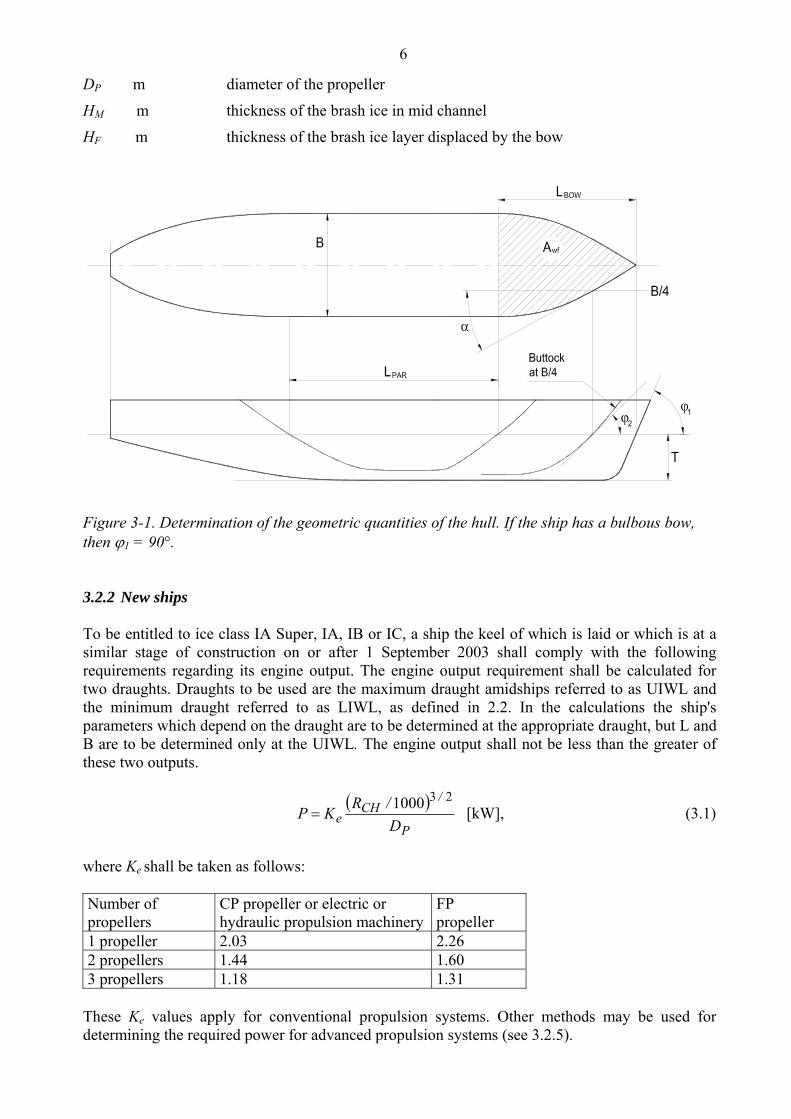
DP m diameter of the propeller
HM m thickness of the brash ice in mid channel
HF m thickness of the brash ice layer displaced by the bow
Figure 3-1. Determination of the geometric quantities of the hull. If the ship has a bulbous bow, then 1 = 90°. 3.2.2 New ships To be entitled to ice class IA Super, IA, IB or IC, a ship the keel of which is laid or which is at a similar stage of construction on or after 1 September 2003 shall comply with the following requirements regarding its engine output. The engine output requirement shall be calculated for two draughts. Draughts to be used are the maximum draught amidships referred to as UIWL and the minimum draught referred to as LIWL, as defined in 2.2. In the calculations the ship's parameters which depend on the draught are to be determined at the appropriate draught, but L and B are to be determined only at the UIWL. The engine output shall not be less than the greater of these two outputs.
P
/CH
e D
/RKP
231000 [kW], (3.1)
where Ke shall be taken as follows: Number of propellers
CP propeller or electric or hydraulic propulsion machinery
FP propeller
1 propeller 2.03 2.26 2 propellers 1.44 1.60 3 propellers 1.18 1.31
These Ke values apply for conventional propulsion systems. Other methods may be used for determining the required power for advanced propulsion systems (see 3.2.5).
7
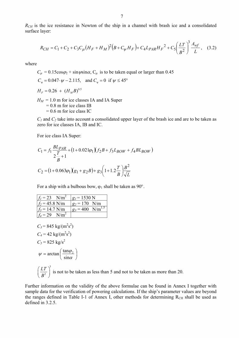
RCH is the ice resistance in Newton of the ship in a channel with brash ice and a consolidated surface layer:
L
A
B
LTCHLCHCBHHCCCCR
wfFPARFMFCH
3
252
42
321
, (3.2)
where
C = 0.15cos2 + sinsin, C is to be taken equal or larger than 0.45
ψ ψ0.047 2.115, and 0 if 45C C
0.50.26 ( )F MH H B
HM = 1.0 m for ice classes IA and IA Super = 0.8 m for ice class IB = 0.6 m for ice class IC
C1 and C2 take into account a consolidated upper layer of the brash ice and are to be taken as zero for ice classes IA, IB and IC. For ice class IA Super:
L
B
B
T.gBgg.C
BLfLfBf.
B
TBL
fC BOWBOWPAR
2
32112
432111
21106301
0210112
For a ship with a bulbous bow, 1 shall be taken as 90. f1 = 23 N/m2 g1 = 1530 N f2 = 45.8 N/m g2 = 170 N/m f3 = 14.7 N/m g3 = 400 N/m1.5
f4 = 29 N/m2 C3 = 845 kg/(m2s2)
C4 = 42 kg/(m2s2)
C5 = 825 kg/s2
sin
tanarctan 2
3
2
LT
B
is not to be taken as less than 5 and not to be taken as more than 20.
Further information on the validity of the above formulae can be found in Annex I together with sample data for the verification of powering calculations. If the ship’s parameter values are beyond the ranges defined in Table I-1 of Annex I, other methods for determining RCH shall be used as defined in 3.2.5.

8
3.2.3 Existing ships of ice class IB or IC To be entitled to retain ice class IB or IC a ship, on which the ice class regulations 1985 (2.9.1985, No. 2575/85/307 as amended) apply, shall comply with the required minimum engine output as defined in section 3.2.1 of the ice class regulations 1985. For ease of reference the provisions for ice classes IB and IC of section 3.2.1 of the ice class regulations 1985 are given in Annex II of these regulations. 3.2.4 Existing ships of ice class IA Super or IA To be entitled to retain ice class IA Super or IA a ship, the keel of which has been laid or which has been at a similar stage of construction before 1 September 2003, shall comply with the requirements in section 3.2.2 above at the following dates:
- 1 January 2005 or - 1 January in the year when 20 years has elapsed since the year the ship was delivered,
whichever occurs the latest.
When, for an existing ship, values for some of the hull form parameters required for the calculation method in section 3.2.2 are difficult to obtain, the following alternative formulae can be used:
4
65803
252
42
321B
B
LTCLHCH.BHHCCCR FFMFCH
, (3.3)
where for ice class IA, C1 and C2 shall be taken as zero.
For ice class IA Super, ship without a bulb, C1 and C2 shall be calculated as follows:
L
B
B
T.gBgg.C
BLfLfBf.
B
TBL
fC
2
3212
43211
211523
84112
For ice class IA Super, ship with a bulb, C1 and C2 shall be calculated as follows:
L
B
B
T.gBgg.C
BLfLfBf.
B
TBL
fC
2
3212
43211
211676
89212
,
where f1 = 10.3 N/m2 g1 = 1530 N f2 = 45.8 N/m g2 = 170 N/m f3 = 2.94 N/m g3 = 400 N/m1.5
f4 = 5.8 N/m2
9
C3 = 460 kg/(m2s2)
C4 = 18.7 kg/(m2s2)
C5 = 825 kg/s2 3
2
LT
B
is not to be taken as less than 5 and not to be taken as more than 20.
3.2.5 Other methods of determining Ke or RCH For an individual ship, in lieu of the Ke or RCH values defined in 3.2.2 and 3.2.3, the use of Ke or RCH values based on more exact calculations or values based on model tests may be approved. Such an approval will be given on the understanding that it can be revoked if experience of the ship’s performance in practice motivates this. The design requirement for ice classes is a minimum speed of 5 knots in the following brash ice channels:
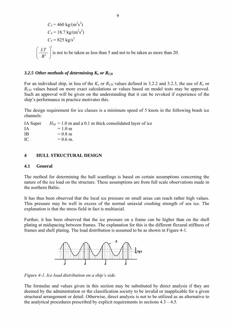
IA Super HM = 1.0 m and a 0.1 m thick consolidated layer of ice IA = 1.0 m IB = 0.8 m IC = 0.6 m. 4 HULL STRUCTURAL DESIGN 4.1 General The method for determining the hull scantlings is based on certain assumptions concerning the nature of the ice load on the structure. These assumptions are from full scale observations made in the northern Baltic. It has thus been observed that the local ice pressure on small areas can reach rather high values. This pressure may be well in excess of the normal uniaxial crushing strength of sea ice. The explanation is that the stress field in fact is multiaxial. Further, it has been observed that the ice pressure on a frame can be higher than on the shell plating at midspacing between frames. The explanation for this is the different flexural stiffness of frames and shell plating. The load distribution is assumed to be as shown in Figure 4-1.
Figure 4-1. Ice load distribution on a ship’s side. The formulae and values given in this section may be substituted by direct analysis if they are deemed by the administration or the classification society to be invalid or inapplicable for a given structural arrangement or detail. Otherwise, direct analysis is not to be utilized as an alternative to the analytical procedures prescribed by explicit requirements in sections 4.3 – 4.5.
10
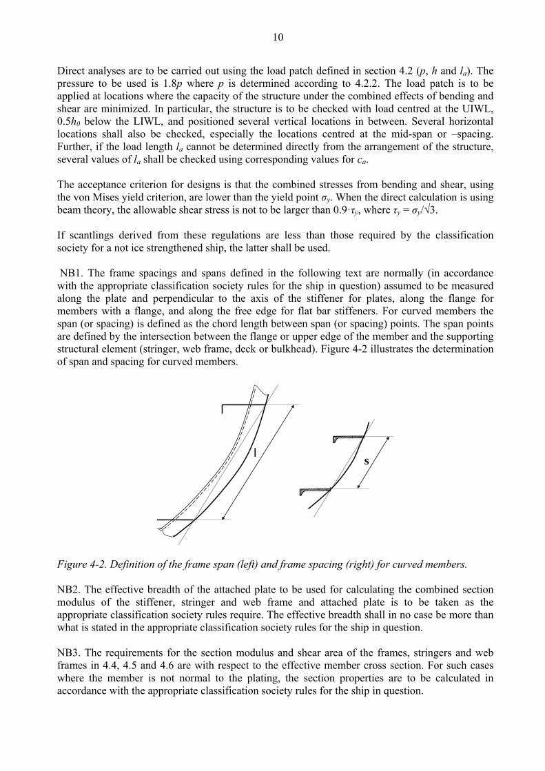
Direct analyses are to be carried out using the load patch defined in section 4.2 (p, h and la). The pressure to be used is 1.8p where p is determined according to 4.2.2. The load patch is to be applied at locations where the capacity of the structure under the combined effects of bending and shear are minimized. In particular, the structure is to be checked with load centred at the UIWL, 0.5h0 below the LIWL, and positioned several vertical locations in between. Several horizontal locations shall also be checked, especially the locations centred at the mid-span or –spacing. Further, if the load length la cannot be determined directly from the arrangement of the structure, several values of la shall be checked using corresponding values for ca. The acceptance criterion for designs is that the combined stresses from bending and shear, using the von Mises yield criterion, are lower than the yield point σy. When the direct calculation is using beam theory, the allowable shear stress is not to be larger than 0.9·τy, where τy = σy/√3. If scantlings derived from these regulations are less than those required by the classification society for a not ice strengthened ship, the latter shall be used. NB1. The frame spacings and spans defined in the following text are normally (in accordance with the appropriate classification society rules for the ship in question) assumed to be measured along the plate and perpendicular to the axis of the stiffener for plates, along the flange for members with a flange, and along the free edge for flat bar stiffeners. For curved members the span (or spacing) is defined as the chord length between span (or spacing) points. The span points are defined by the intersection between the flange or upper edge of the member and the supporting structural element (stringer, web frame, deck or bulkhead). Figure 4-2 illustrates the determination of span and spacing for curved members.
ls
Figure 4-2. Definition of the frame span (left) and frame spacing (right) for curved members. NB2. The effective breadth of the attached plate to be used for calculating the combined section modulus of the stiffener, stringer and web frame and attached plate is to be taken as the appropriate classification society rules require. The effective breadth shall in no case be more than what is stated in the appropriate classification society rules for the ship in question. NB3. The requirements for the section modulus and shear area of the frames, stringers and web frames in 4.4, 4.5 and 4.6 are with respect to the effective member cross section. For such cases where the member is not normal to the plating, the section properties are to be calculated in accordance with the appropriate classification society rules for the ship in question.

11
4.1.1 Hull regions For the purpose of this section, the ship's hull is divided into regions as follows (see also Figure 4-3): Bow region: From the stem to a line parallel to and 0.04·L aft of the forward borderline of the part of the hull where the waterlines run parallel to the centerline. For ice classes IA Super and IA the overlap over the borderline need not exceed 6 meters, for ice classes IB and IC this overlap need not exceed 5 meters.
Midbody region: From the aft boundary of the Bow region to a line parallel to and 0.04·L aft of the aft borderline of the part of the hull where the waterlines run parallel to the centerline. For ice classes IA Super and IA the overlap over the borderline need not exceed 6 meters, for ice classes IB and IC this overlap need not exceed 5 meters.
Stern region: From the aft boundary of the Midbody region to the stern. L shall be taken as the ship's rule length used by the classification society.
Figure 4-3. Ice strengthened regions of the hull. 4.2 Ice load 4.2.1 Height of the ice load area An ice-strengthened ship is assumed to operate in open sea conditions corresponding to a level ice thickness not exceeding ho. The design ice load height (h) of the area actually under ice pressure at any particular point of time is, however, assumed to be only a fraction of the ice thickness. The values for ho and h are given in the following table.
Ice Class ho [m] h [m] IA Super IA IB IC
1.0 0.8 0.6 0.4
0.35 0.30 0.25 0.22
12
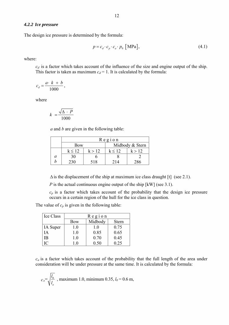
4.2.2 Ice pressure The design ice pressure is determined by the formula: 0 MPad p ap c c c p , (4.1)
where:
cd is a factor which takes account of the influence of the size and engine output of the ship. This factor is taken as maximum cd = 1. It is calculated by the formula:
1000d
a k bc
,
where
1000
Pk
a and b are given in the following table:
is the displacement of the ship at maximum ice class draught [t] (see 2.1).
P is the actual continuous engine output of the ship [kW] (see 3.1).
cp is a factor which takes account of the probability that the design ice pressure occurs in a certain region of the hull for the ice class in question.
The value of cp is given in the following table:
ca is a factor which takes account of the probability that the full length of the area under consideration will be under pressure at the same time. It is calculated by the formula:
0=a
a
lc
l , maximum 1.0, minimum 0.35, l0 = 0.6 m,
R e g i o n
Bow Midbody & Stern a b
k 12 k 12 k 12 k 12 30 230
6 518
8 214
2 286
Ice Class R e g i o n Bow Midbody Stern
IA Super IA IB IC
1.0 1.0 1.0 1.0
1.0 0.85 0.70 0.50
0.75 0.65 0.45 0.25

13
where la shall be taken as follows:
po is the nominal ice pressure; the value 5.6 MPa shall be used. 4.3 Shell plating 4.3.1 Vertical extension of ice strengthening for plating (ice belt) The vertical extension of the ice belt shall be as follows (see Figure 4-3):
Ice class Hull region
Above UIWL Below LIWL
IA Super
Bow
0.60 m 1.20 m
Midbody
Stern 1.0 m
IA
Bow
0.50 m
0.90 m
Midbody 0.75 m
Stern
IB and IC
Bow
0.40 m
0.70 m
Midbody 0.60 m
Stern
In addition, the following areas shall be strengthened: Fore foot: For ice class IA Super, the shell plating below the ice belt from the stem to a position five main frame spaces abaft the point where the bow profile departs from the keel line shall have at least the thickness required in the ice belt in the midbody region.
Upper bow ice belt: For ice classes IA Super and IA on ships with an open water service speed equal to or exceeding 18 knots, the shell plate from the upper limit of the ice belt to 2 m above it and from the stem to a position at least 0.2 L abaft the forward perpendicular, shall have at least the thickness required in the ice belt in the midbody region. A similar strengthening of the bow region is advisable also for a ship with a lower service speed, when it is, e.g. on the basis of the model tests, evident that the ship will have a high bow wave. Sidescuttles shall not be situated in the ice belt. If the weather deck in any part of the ship is situated below the upper limit of the ice belt (e.g. in way of the well of a raised quarter decker), the bulwark shall be given at least the same strength as is required for the shell in the ice belt. The strength of the construction of the freeing ports shall meet the same requirements.
Structure Type of framing la [m] Shell Transverse Frame spacing
Longitudinal 1.7 frame spacing Frames Transverse Frame spacing
Longitudinal Span of frame Ice stringer Span of stringer Web frame 2 web frame spacing

14
4.3.2 Plate thickness in the ice belt For transverse framing the thickness of the shell plating shall be determined by the formula:
1 667 mmPLc
y
f pt s t
(4.2)
For longitudinal framing the thickness of the shell plating shall be determined by the formula:
cy
tf
pst
2667 [mm], (4.3)
where
s is the frame spacing [m]
pPL = 0.75 p [MPa], where p is as given in 4.2.2
1 2
4.21.3 ; maximum 1.0
( / 1.8)f
h s
2
0.40.6 ; when h/s 1
( / )f
h s
f2 = 1.4 - 0.4 (h/s); when 1 h/s 1.8
where h is as given in 4.2.1
y is yield stress of the material [N/mm2], for which the following values shall be used:
y = 235 N/mm2 for normal-strength hull structural steel
y = 315 N/mm2 or higher for high-strength hull structural steel
If steels with different yield stress are used, the actual values may be substituted for the above ones if accepted by the classification society.
tc is increment for abrasion and corrosion [mm]; normally tc shall be 2 mm; if a special surface coating, by experience shown capable to withstand the abrasion of ice, is applied and maintained, lower values may be approved.
4.4 Frames 4.4.1 Vertical extension of ice strengthening for framing The vertical extension of the ice strengthening of the framing shall be at least as follows:

15
Ice class Hull region
Above UIWL Below LIWL
IA Super
Bow
1.2 m
Down to double bottom or below top of the floors
Midbody 2.0 m
Stern 1.6 m
IA, IB and IC
Bow
1.0 m
1.6 m
Midbody 1.3 m
Stern 1.0 m
Where an upper bow ice belt is required (see 4.3.1), the ice-strengthened part of the framing shall be extended at least to the top of this ice belt. Where the ice-strengthening would go beyond a deck or a tanktop (or tank bottom) by no more than 250 mm, it can be terminated at that deck or tanktop (or tank bottom).
4.4.2 Transverse frames 4.4.2.1 Section modulus and shear area The section modulus of a main or intermediate transverse frame shall be calculated by the formula:
610ytm
lhspZ
[cm3], (4.4)
and the effective shear area is calculated from
43 102
3
y
shpfA
[cm2], (4.5)
where
p is ice pressure as given in 4.2.2 [MPa]
s is frame spacing [m]
h is height of load area as given in 4.2.1 [m]
l is span of the frame [m]
mt = 7
7 -5 /om
h l
f3 is a factor which takes into account the maximum shear force versus the load location and the shear stress distribution, f3 = 1.2
y is yield stress as in 4.3.2 [N/mm2]

16
mo takes the boundary conditions into account. The values are given in the following table:
The boundary conditions are those for the main and intermediate frames. Load is applied at mid span. Where less than 15% of the span, l, of the frame is situated within the ice-strengthening zone for frames as defined in 4.4.1, ordinary frame scantlings may be used. 4.4.2.2 Upper end of transverse framing The upper end of the strengthened part of a main frame and of an intermediate ice frame shall be attached to a deck, tanktop (or tank bottom) or an ice stringer (section 4.5). Where a frame terminates above a deck or a stringer which is situated at or above the upper limit of the ice belt (section 4.3.1), the part above the deck or stringer may have the scantlings required by the classification society for an non ice-strengthened ship and the upper end of an intermediate frame may be connected to the adjacent frames by a horizontal member having the same scantlings as the main frame. 4.4.2.3 Lower end of transverse framing The lower end of the strengthened part of a main frame and of an intermediate ice frame shall be attached to a deck, tanktop (or tank bottom) or an ice stringer (section 4.5).

17
Where an intermediate frame terminates below a deck, tanktop (or tank bottom) or ice stringer which is situated at or below the lower limit of the ice belt (section 4.3.1), the lower end may be connected to the adjacent main frames by a horizontal member of the same scantlings as the main frames. Note that the main frames below the lower edge of ice belt must be ice strengthened, see 4.4.1. 4.4.3 Longitudinal frames The following requirements are intended for longitudinal frames with all end conditions. 4.4.3.1 Frames with and without brackets The section modulus of a longitudinal frame shall be calculated by the formula:
62
4 10ym
lhpfZ
[cm3], (4.6)
and effective shear area of a longitudinal frame shall be:
454 102
3
y
lhpffA
[cm2]. (4.7)
In calculating the actual shear area of the frames, the shear area of the brackets is not to be taken into account. In the formulae given above:
f4 is a factor which takes account of the load distribution to adjacent frames:
f4 = (1 - 0.2 h/s)
f5 is a factor which takes into account the maximum shear force versus load location and the shear stress distribution:
f5 = 2.16
p is ice pressure as given in 4.2.2 [MPa]
h is height of load area as given in 4.2.1 [m]
s is frame spacing [m]
l is total span of frame [m]
m is a boundary condition factor; m = 13.3 for a continuous beam; where the boundary conditions deviate significantly from those of a continuous beam, e.g. in an end field, a smaller boundary factor may be required. For frames without brackets a value m = 11.0 is to be used.
y is yield stress as in 4.3.2 [N/mm2].
18
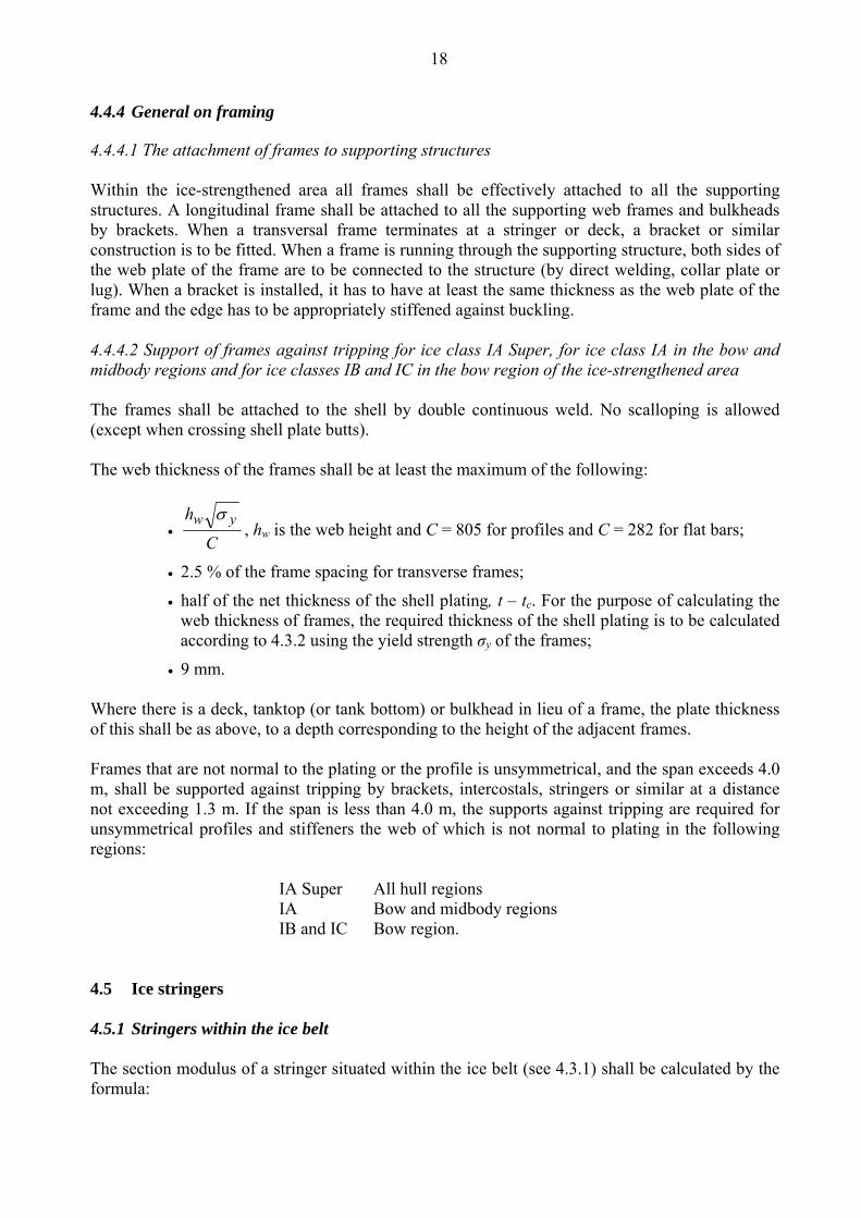
4.4.4 General on framing 4.4.4.1 The attachment of frames to supporting structures Within the ice-strengthened area all frames shall be effectively attached to all the supporting structures. A longitudinal frame shall be attached to all the supporting web frames and bulkheads by brackets. When a transversal frame terminates at a stringer or deck, a bracket or similar construction is to be fitted. When a frame is running through the supporting structure, both sides of the web plate of the frame are to be connected to the structure (by direct welding, collar plate or lug). When a bracket is installed, it has to have at least the same thickness as the web plate of the frame and the edge has to be appropriately stiffened against buckling. 4.4.4.2 Support of frames against tripping for ice class IA Super, for ice class IA in the bow and midbody regions and for ice classes IB and IC in the bow region of the ice-strengthened area The frames shall be attached to the shell by double continuous weld. No scalloping is allowed (except when crossing shell plate butts). The web thickness of the frames shall be at least the maximum of the following:
C
h yw , hw is the web height and C = 805 for profiles and C = 282 for flat bars;
2.5 % of the frame spacing for transverse frames;
half of the net thickness of the shell plating, t – tc. For the purpose of calculating the web thickness of frames, the required thickness of the shell plating is to be calculated according to 4.3.2 using the yield strength σy of the frames;
9 mm. Where there is a deck, tanktop (or tank bottom) or bulkhead in lieu of a frame, the plate thickness of this shall be as above, to a depth corresponding to the height of the adjacent frames. Frames that are not normal to the plating or the profile is unsymmetrical, and the span exceeds 4.0 m, shall be supported against tripping by brackets, intercostals, stringers or similar at a distance not exceeding 1.3 m. If the span is less than 4.0 m, the supports against tripping are required for unsymmetrical profiles and stiffeners the web of which is not normal to plating in the following regions: IA Super All hull regions IA Bow and midbody regions IB and IC Bow region. 4.5 Ice stringers 4.5.1 Stringers within the ice belt The section modulus of a stringer situated within the ice belt (see 4.3.1) shall be calculated by the formula:

19
62
76 10ym
lhpffZ
[cm3]. (4.8)
The effective shear area shall be:
4876 102
3
y
lhpfffA
[cm2], (4.9)
where
p is ice pressure as given in 4.2.2 [MPa]
h is height of load area as given in 4.2.1 [m]
The product p h shall not be taken as less than 0.15.
l is span of the stringer [m]
m is a boundary condition factor as defined in 4.4.3
f6 is a factor which takes account of the distribution of load to the transverse frames; to be taken as 0.9
f7 is the safety factor of stringers; to be taken as 1.8
f8 is a factor that takes into account the maximum shear force versus load location and the shear stress distribution; f8 = 1.2
y is yield stress as in 4.3.2.
4.5.2 Stringers outside the ice belt The section modulus of a stringer situated outside the ice belt but supporting ice-strengthened frames shall be calculated by the formula:
62
109 101
ss
yl/h
m
lhpffZ
[cm3]. (4.10)
The effective shear area shall be:
411109 1012
3
ssy
l/hlhpfff
A
[cm2], (4.11)
where
p is ice pressure as given in 4.2.2 [MPa]
h is height of load area as given in 4.2.1 [m]
The product p h shall not be taken as less than 0.15.
l is span of stringer [m]
m is boundary condition factor as defined in 4.4.3
ls is the distance to the adjacent ice stringer [m]
hs is the distance to the ice belt [m]

20
f9 is a factor which takes account of the distribution of load to the transverse frames; to be taken as 0.80
f10 is the safety factor of stringers; to be taken as 1.8
f11 is a factor that takes into account the maximum shear force versus load location and the shear stress distribution; f11 = 1.2
y is yield stress of material as in 4.3.2.
4.5.3 Deck strips Narrow deck strips abreast of hatches and serving as ice stringers shall comply with the section modulus and shear area requirements in 4.5.1 and 4.5.2 respectively. In the case of very long hatches the classification society may permit the product p h to be taken as less than 0.15 but in no case as less than 0.10. Regard shall be paid to the deflection of the ship's sides due to ice pressure in way of very long (more than B/2) hatch openings when designing weatherdeck hatch covers and their fittings. 4.6 Web frames 4.6.1 Ice load The ice load transferred to a web frame from an ice stringer or from longitudinal framing shall be calculated by the formula: ShpfF 12 [MN], (4.12) where
p is ice pressure as given in 4.2.2 [MPa], in calculating ca however, la shall be taken as 2S.
h is height of load area as given in 4.2.1 [m]
The product p h shall not be taken as less than 0.15
S is distance between web frames [m]
f12 is the safety factor of web frames; to be taken as 1.8. In case the supported stringer is outside the ice belt, the force F shall be multiplied by (1- hs/ls), where hs and ls shall be taken as defined in 4.5.2. 4.6.2 Section modulus and shear area The section modulus and shear area of web frames shall be calculated by the formulae: The effective shear area:
y
QfA
4
13 103 [cm2], (4.13)
21
where
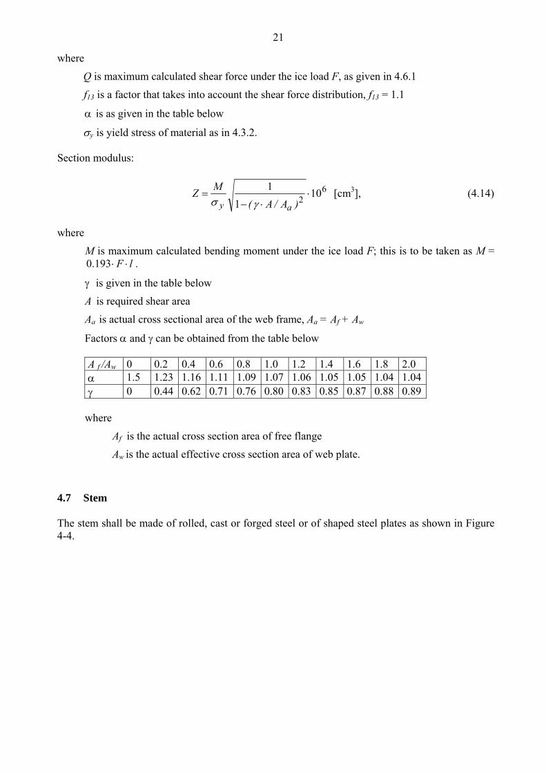
Q is maximum calculated shear force under the ice load F, as given in 4.6.1
f13 is a factor that takes into account the shear force distribution, f13 = 1.1
is as given in the table below
y is yield stress of material as in 4.3.2. Section modulus:
62
101
1
)A/A(
MZ
ay [cm3], (4.14)
where
M is maximum calculated bending moment under the ice load F; this is to be taken as M = 0.193 F l .
is given in the table below
A is required shear area
Aa is actual cross sectional area of the web frame, Aa = Af + Aw
Factors and can be obtained from the table below A f /Aw 0 0.2 0.4 0.6 0.8 1.0 1.2 1.4 1.6 1.8 2.0 1.5 1.23 1.16 1.11 1.09 1.07 1.06 1.05 1.05 1.04 1.04 0 0.44 0.62 0.71 0.76 0.80 0.83 0.85 0.87 0.88 0.89
where
Af is the actual cross section area of free flange
Aw is the actual effective cross section area of web plate.
4.7 Stem The stem shall be made of rolled, cast or forged steel or of shaped steel plates as shown in Figure 4-4.

22
Figure 4-4. Examples of suitable stems. The plate thickness of a shaped plate stem and in the case of a blunt bow, any part of the shell where α ≥ 30o and ψ ≥ 75o (see section 3.2.1 for angle definitions), shall be calculated according to the formula in 4.3.2 assuming that:
s is spacing of elements supporting the plate [m]
pPL = p [MPa] (see 4.3.2)
la is spacing of vertical supporting elements [m] The stem and the part of a blunt bow defined above shall be supported by floors or brackets spaced not more than 0.6 m apart and having a thickness of at least half the plate thickness. The reinforcement of the stem shall extend from the keel to a point 0.75 m above UIWL or, in case an upper bow ice belt is required (4.3.1), to the upper limit of this. 4.8 Stern The introduction of new propulsion arrangements with azimuthing thrusters or ”podded” propellers, which provide an improved manoeuvrability, will result in increased ice loading of the Stern region and the stern area. This fact should be considered in the design of the aft/stern structure. In order to avoid very high loads on propeller blade tips, the minimum distance between propeller(s) and hull (including stern frame) should not be less than h0 (see 4.2.1). On twin and triple screw ships the ice strengthening of the shell and framing shall be extended to the double bottom for 1.5 metres forward and aft of the side propellers. Shafting and stern tubes of side propellers shall normally be enclosed within plated bossings. If detached struts are used, their design, strength and attachments to the hull shall be duly considered.
23
5 RUDDER AND STEERING ARRANGEMENTS The scantlings of rudder post, rudder stock, pintles, steering engine etc. as well as the capability of the steering engine shall be determined according to the rules of the Classification Society. The maximum service speed of the ship to be used in these calculations shall, however, not be taken as less than stated below: IA Super 20 knots IA 18 knots IB 16 knots IC 14 knots If the actual maximum service speed of the ship is higher, that speed shall be used. The local scantlings of rudders are to be determined assuming that the whole rudder belongs to the ice belt. Further, the rudder plating and frames are to be designed using the ice pressure p for the plating and frames in the midbody region. For ice classes IA and IA Super, the rudder (rudder stock and the upper part of the rudder) shall be protected from direct contact with intact ice by an ice knife that extends below the LIWL, if practicable (or equivalent means). Special consideration shall be given to the design of the rudder and the ice knife for ships with flap-type rudders. For ice classes IA and IA Super, due regard shall be paid to the large loads that arise when the rudder is forced out of the midship position while going astern in ice or into ice ridges. Suitable arrangement such as rudder stoppers shall be installed to absorb these loads. Relief valves for hydraulic pressure in rudder turning mechanism(s) shall be installed. The components of the steering gear (e.g. rudder stock, rudder coupling, rudder horn etc.) shall be dimensioned to withstand loads causing yield stresses in the rudder stock. 6 PROPULSION MACHINERY
6.1 Scope
These regulations apply to propulsion machinery covering open- and ducted-type propellers with controllable pitch or fixed pitch design for the ice classes IA Super, IA, IB and IC. The given loads are the expected ice loads for the whole ship’s service life under normal operational conditions, including loads resulting from the changing rotational direction of FP propellers. However, these loads do not cover off-design operational conditions, for example when a stopped propeller is dragged through ice. The regulations also apply to azimuthing and fixed thrusters for main propulsion, considering loads resulting from propeller/ice interaction. However, the load models of the regulations do not include propeller/ice interaction loads when ice enters the propeller of a turned azimuthing thruster from the side (radially) or load cases when ice block hits on the propeller hub of a pulling propeller. Ice loads resulting from ice impacts on the body of thrusters have to be estimated, but ice load formulae are not available.
6.2 Definitions
c m chord length of blade section
c0.7 m chord length of blade section at 0.7R propeller radius

24
CP controllable pitch
D m propeller diameter
d m external diameter of propeller hub (at propeller plane)
limitD m limit value for propeller diameter
EAR expanded blade area ratio
bF kN maximum backward blade force for the ship’s service life
exF kN ultimate blade load resulting from blade loss through plastic bending
fF kN maximum forward blade force for the ship’s service life
Fice kN ice load
(Fice)max kN maximum ice load for the ship’s service life
FP fixed pitch
0h m depth of the propeller centreline from lower ice waterline
Hice m thickness of maximum design ice block entering to propeller
I kgm2 equivalent mass moment of inertia of all parts on engine side of component under consideration
tI kgm2 equivalent mass moment of inertia of the whole propulsion system
k shape parameter for Weibull distribution
LIWL m lower ice waterline
m slope for SN curve in log/log scale
BLM kNm blade bending moment
MCR maximum continuous rating
n rev./s propeller rotational speed
nn rev./s nominal propeller rotational speed at MCR in free running condition
classN reference number of impacts per propeller rotational speed per ice class
iceN total number of ice loads on propeller blade for the ship’s service life
NR reference number of load for equivalent fatigue stress (108 cycles)
NQ number of propeller revolutions during a milling sequence
7.0P m propeller pitch at 0.7R radius
P0.7n m propeller pitch at 0.7R radius at MCR in free running condition
P0.7b m propeller pitch at 0.7R radius at MCR in bollard condition
Q kNm torque
emaxQ kNm maximum engine torque
maxQ kNm maximum torque on the propeller resulting from propeller/ice interaction
Q motor kNm electric motor peak torque
nQ kNm nominal torque at MCR in free running condition
Qr kNm maximum response torque along the propeller shaft line
smaxQ kNm maximum spindle torque of the blade for the ship’s service life

25
R m propeller radius
r m blade section radius
T kN propeller thrust
bT kN maximum backward propeller ice thrust for the ship’s service life
fT kN maximum forward propeller ice thrust for the ship’s service life
nT kN propeller thrust at MCR in free running condition
Tr kN maximum response thrust along the shaft line
t m maximum blade section thickness
Z number of propeller blades
αi [deg] duration of propeller blade/ice interaction expressed in rotation angle
the reduction factor for fatigue; scatter and test specimen size effect
the reduction factor for fatigue; variable amplitude loading effect
m the reduction factor for fatigue; mean stress effect
a reduction factor for fatigue correlating the maximum stress amplitude to the equivalent fatigue stress for 108 stress cycles
2.0 MPa proof yield strength (at 0.2% offset) of blade material
exp MPa mean fatigue strength of blade material at 108 cycles to failure in sea water
fat MPa equivalent fatigue ice load stress amplitude for 108 stress cycles
fl MPa characteristic fatigue strength for blade material
ref MPa reference stress uref 4.06.0 2.0
2ref MPa reference stress
uref 7.02 or
uref 4.06.0 2.02 whichever is less
st MPa maximum stress resulting from Fb or fF
u MPa ultimate tensile strength of blade material
bmaxice MPa principal stress caused by the maximum backward propeller ice load
fmaxice MPa principal stress caused by the maximum forward propeller ice load
maxice MPa maximum ice load stress amplitude

26
Table 6-1. Definition of loads Definition Use of the load in design process Fb The maximum lifetime backward force on a
propeller blade resulting from propeller/ice interaction, including hydrodynamic loads on that blade. The direction of the force is perpendicular to 0.7R chord line. See Figure 6-1.
Design force for strength calculation of the propeller blade.
Ff The maximum lifetime forward force on a propeller blade resulting from propeller/ice interaction, including hydrodynamic loads on that blade. The direction of the force is perpendicular to 0.7R chord line.
Design force for calculation of strength of the propeller blade.
Qsmax The maximum lifetime spindle torque on a propeller blade resulting from propeller/ice interaction, including hydrodynamic loads on that blade.
In designing the propeller strength, the spindle torque is automatically taken into account because the propeller load is acting on the blade as distributed pressure on the leading edge or tip area.
Tb The maximum lifetime thrust on propeller (all blades) resulting from propeller/ice interaction. The direction of the thrust is the propeller shaft direction and the force is opposite to the hydrodynamic thrust.
Is used for estimation of the response thrust Tr. Tb can be used as an estimate
of excitation for axial vibration calculations. However, axial vibration calculations are not required in the rules.
Tf The maximum lifetime thrust on propeller (all blades) resulting from propeller/ice interaction. The direction of the thrust is the propeller shaft direction acting in the direction of hydrodynamic thrust.
Is used for estimation of the response thrust Tr. Tf can be used as an estimate
of excitation for axial vibration calculations. However, axial vibration calculations are not required in the rules.
Qmax The maximum ice-induced torque resulting from propeller/ice interaction on one propeller blade, including hydrodynamic loads on that blade.
Is used for estimation of the response torque (Qr) along the propulsion shaft
line and as excitation for torsional vibration calculations.
Fex Ultimate blade load resulting from blade loss through plastic bending. The force that is needed to cause total failure of the blade so that plastic hinge is caused to the root area. The force is acting on 0.8R. Spindle arm is to be taken as 2/3 of the distance between the axis of blade rotation and leading/trailing edge (whichever is the greater) at the 0.8R radius.
Blade failure load is used to dimension the blade bolts, pitch control mechanism, propeller shaft, propeller shaft bearing and trust bearing. The objective is to guarantee that total propeller blade failure should not cause damage to other components.
Qr Maximum response torque along the propeller shaft line, taking into account the dynamic behavior of the shaft line for ice excitation (torsional vibration) and hydrodynamic mean torque on propeller.
Design torque for propeller shaft line components.
Tr Maximum response thrust along shaft line, taking into account the dynamic behavior of the shaft line for ice excitation (axial vibration) and hydrodynamic mean thrust on propeller.
Design thrust for propeller shaft line components.

27
Figure 6-1. Direction of the backward blade force resultant taken perpendicular to chord line at radius 0.7R. Ice contact pressure at leading edge is shown with small arrows.
6.3 Design ice conditions
In estimating the ice loads of the propeller for ice classes, different types of operation as given in Table 6-2 were taken into account. For the estimation of design ice loads, a maximum ice block size is determined. The maximum design ice block entering the propeller is a rectangular ice block with the dimensions 2 3ice ice iceH H H . The thickness of the ice block (Hice) is given in Table 6-3.
Table 6-2. Ice class Operation of the ship IA Super Operation in ice channels and in level ice
The ship may proceed by ramming
IA, IB, IC Operation in ice channels
Table 6-3. IA Super IA IB IC
Thickness of the design maximum ice block entering the propeller (Hice)
1.75 m 1.5 m 1.2 m 1.0 m
Back side
Shaft direction
Fb
Direction of rotation

28
6.4 Materials 6.4.1 Materials exposed to sea water Materials of components exposed to sea water, such as propeller blades, propeller hubs, and thruster body, shall have an elongation of not less than 15% on a test specimen, the gauge length of which is five times the diameter. A Charpy V impact test shall be carried out for materials other than bronze and austenitic steel. An average impact energy value of 20 J taken from three tests is to be obtained at minus 10 ºC. 6.4.2 Materials exposed to sea water temperature Materials exposed to sea water temperature shall be of steel or other ductile material. An average impact energy value of 20 J taken from three tests is to be obtained at minus 10 ºC. This requirement applies to blade bolts, CP mechanisms, shaft bolts, strut-pod connecting bolts etc. This does not apply to surface hardened components, such as bearings and gear teeth.
6.5 Design loads
The given loads are intended for component strength calculations only and are total loads including ice-induced loads and hydrodynamic loads during propeller/ice interaction. The values of the parameters in the formulae in this section shall be given in the units shown in the symbol list. If the propeller is not fully submerged when the ship is in ballast condition, the propulsion system shall be designed according to ice class IA for ice classes IB and IC. 6.5.1 Design loads on propeller blades Fb is the maximum force experienced during the lifetime of the ship that bends a propeller blade backwards when the propeller mills an ice block while rotating ahead. Ff is the maximum force experienced during the lifetime of the ship that bends a propeller blade forwards when the propeller mills an ice block while rotating ahead. Fb and Ff originate from different propeller/ice interaction phenomena, not acting simultaneously. Hence they are to be applied to one blade separately. 6.5.1.1 Maximum backward blade force Fb for open propellers
0.3
0.7 2limit27 [kN], when b
EARF n D D D D
Z
(6.1)
0.3
0.7 1.4limit23 [kN], when b ice
EARF n D D H D D
Z
, (6.2)
where
4.185.0 icelimit HD [m]
n is the nominal rotational speed (at MCR in free running condition) for a CP propeller and 85% of the nominal rotational speed (at MCR in free running condition) for an FP propeller.

29
6.5.1.2 Maximum forward blade force Ff for open propellers
2limit250 [kN], when f
EARF D D D
Z
(6.3)
limit
1500 [kN], when
1f ice
EARF D H D D
dZD
(6.4)
where
icelimit H
D
dD
1
2 [m].
6.5.1.3 Loaded area on the blade for open propellers Load cases 1-4 have to be covered, as given in Table 6-4 below, for CP and FP propellers. In order to obtain blade ice loads for a reversing propeller, load case 5 also has to be covered for FP propellers.
30
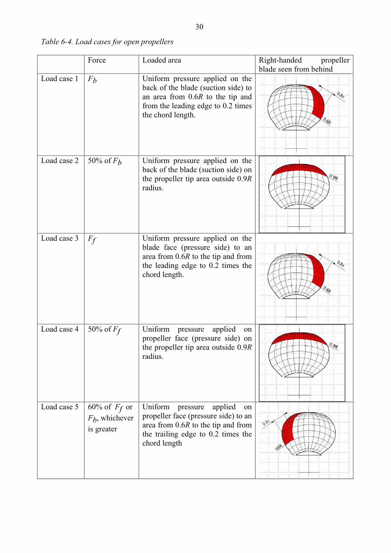
Table 6-4. Load cases for open propellers Force Loaded area Right-handed propeller
blade seen from behind Load case 1 Fb Uniform pressure applied on the
back of the blade (suction side) to an area from 0.6R to the tip and from the leading edge to 0.2 times the chord length.
Load case 2 50% of Fb Uniform pressure applied on the back of the blade (suction side) on the propeller tip area outside 0.9R radius.
Load case 3 Ff Uniform pressure applied on the blade face (pressure side) to an area from 0.6R to the tip and from the leading edge to 0.2 times the chord length.
Load case 4
50% of Ff Uniform pressure applied on propeller face (pressure side) on the propeller tip area outside 0.9R radius.
Load case 5 60% of Ff or
Fb, whichever
is greater
Uniform pressure applied on propeller face (pressure side) to an area from 0.6R to the tip and from the trailing edge to 0.2 times the chord length

31
6.5.1.4 Maximum backward blade ice force Fb for ducted propellers
0.3
0.7 2limit9.5 [kN], when b
EARF n D D D D
Z
(6.5)
0.3
0.7 0.6 1.4limit66 [kN], when b ice
EARF n D D H D D
Z
, (6.6)
where
icelimit HD 4 [m]
n is the nominal rotational speed (at MCR in free running condition) for a CP propeller and 85% of the nominal rotational speed (at MCR in free running condition) for an FP propeller.
6.5.1.5 Maximum forward blade ice force Ff for ducted propellers
2limit250 [kN], when f
EARF D D D
Z
(6.7)
limit
1500 [kN], when
1f ice
EARF D H D D
dZD
(6.8)
where
icelimit H
D
dD
1
2 [m].
6.5.1.6 Loaded area on the blade for ducted propellers Load cases 1 and 3 have to be covered as given in Table 6-5 for all propellers, and an additional load case (load case 5) for an FP propeller, to cover ice loads when the propeller is reversed.

32
Table 6-5. Load cases for ducted propellers Force Loaded area Right handed propeller
blade seen from behind Load case 1 Fb Uniform pressure applied on the
back of the blade (suction side) to an area from 0.6R to the tip and from the leading edge to 0.2 times the chord length.
Load case 3 Ff Uniform pressure applied on the blade face (pressure side) to an area from 0.6R to the tip and from the leading edge to 0.5 times the chord length.
Load case 5 60% of Ff or
Fb, whichever
is greater
Uniform pressure applied on propeller face (pressure side) to an area from 0.6R to the tip and from the trailing edge to 0.2 times the chord length.
6.5.1.7 Maximum blade spindle torque Qsmax for open and ducted propellers The spindle torque Qsmax around the axis of the blade fitting shall be determined both for the maximum backward blade force bF and forward blade force fF , which are applied as in Table 6-4
and Table 6-5. If the above method gives a value which is less than the default value given by the formula below, the default value shall be used. 0.7Default value 0.25 [kNm]smaxQ F c (6.9)
where 7.0c is the length of the blade section at 0.7R radius and F is either Fb or Ff , whichever
has the greater absolute value. 6.5.1.8 Load distributions for blade loads The Weibull-type distribution (probability that Fice exceeds (Fice)max), as given in Figure 6-2, is used for the fatigue design of the blade.
max
ln
max max
k
iceice
FN
Fice
ice ice
F FP e
F F
(6.10)

33
where k is the shape parameter of the spectrum, Nice is the number of load cycles in the spectrum, and Fice is the random variable for ice loads on the blade, 0 Fice (Fice)max. The shape parameter k=0.75 shall be used for the ice force distribution of an open propeller and the shape parameter k=1.0 for that of a ducted propeller blade.
1,E-07
1,E-06
1,E-05
1,E-04
1,E-03
1,E-02
1,E-01
1,E+00
0 0,2 0,4 0,6 0,8 1
Fice/(Ficemax)
Pro
pabi
lity
of e
xcee
ding
for
N=
1E7
Weibull distribution/k=1
Weibull distribution/k=0.75
Figure 6-2. The Weibull-type distribution (probability that Fice exceeds (Fice)max) that is used for fatigue design. 6.5.1.9 Number of ice loads The number of load cycles per propeller blade in the load spectrum shall be determined according to the formula: 1 2 3 4ice classN k k k k N n , (6.11)
where
Reference number of loads for ice classes Nclass Class IA Super IA IB IC impacts in life/n 6109 6106 6104.3 6101.2
Propeller location factor k1
Centre propeller Wing propellerk1 1 1.35
Propeller type factor k2 type open ducted k2 1 1.1
Propulsion type factor k3 type fixed azimuthing k3 1 1.2

34
The submersion factor k4 is determined from the equation
4 = 0.8 - when 0
= 0.8 - 0.4· when 0 1
= 0.6 - 0.2· when 1 2.5
= 0.1 when 2.5
k f f
f f
f f
f
(6.12)
where the immersion function f is
1/ 2
o iceh Hf
D
, (6.13)
where oh is the depth of the propeller centreline at the lower ice waterline (LIWL) of the
ship. For components that are subject to loads resulting from propeller/ice interaction with all the propeller blades, the number of load cycles (Nice) is to be multiplied by the number of propeller blades (Z). 6.5.2 Axial design loads for open and ducted propellers
6.5.2.1 Maximum ice thrust on propeller Tf and Tb for open and ducted propellers
The maximum forward and backward ice thrusts are: 1.1 [kN]f fT F (6.14)
1.1 [kN]b bT F . (6.15)
6.5.2.2 Design thrust along the propulsion shaft line for open and ducted propellers The design thrust along the propeller shaft line is to be calculated with the formulae below. The greater value of the forward and backward direction loads shall be taken as the design load for both directions. The factors 2.2 and 1.5 take into account the dynamic magnification resulting from axial vibration. In a forward direction 2.2 [kN]r fT T T , (6.16)
in a backward direction 1.5 [kN]r bT T . (6.17)
If the hydrodynamic bollard thrust, T, is not known, T is to be taken as follows:
35
Propeller type TCP propellers (open) 1.25 Tn
CP propellers (ducted) 1.1 Tn
FP propellers driven by turbine or electric motor Tn FP propellers driven by diesel engine (open) 0.85 Tn
FP propellers driven by diesel engine (ducted) 0.75 Tn
Here Tn is the nominal propeller thrust at MCR in the free running open water condition. 6.5.3 Torsional design loads
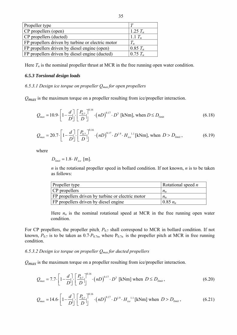
6.5.3.1 Design ice torque on propeller Qmax for open propellers
Qmax is the maximum torque on a propeller resulting from ice/propeller interaction.
0.16
0.17 30.7limit10.9 1 [kNm], when max
PdQ nD D D D
D D
(6.18)
0.16
0.17 1.9 1.10.720.7 1max ice
PdQ nD D H
D D
[kNm], when limitDD , (6.19)
where
icelimit HD 8.1 [m].
n is the rotational propeller speed in bollard condition. If not known, n is to be taken as follows:
Propeller type Rotational speed n CP propellers nn FP propellers driven by turbine or electric motor nn FP propellers driven by diesel engine 0.85 nn
Here nn is the nominal rotational speed at MCR in the free running open water condition.
For CP propellers, the propeller pitch, P0.7 shall correspond to MCR in bollard condition. If not known, P0.7 is to be taken as 0.7P0.7n, where P0.7n is the propeller pitch at MCR in free running condition.
6.5.3.2 Design ice torque on propeller Qmax for ducted propellers Qmax is the maximum torque on a propeller resulting from ice/propeller interaction.
0.16
0.17 30.77.7 1max
PdQ nD D
D D
[kNm] when limitDD , (6.20)
0.16
0.17 1.9 1.10.714.6 1max ice
PdQ nD D H
D D
[kNm] when limitDD , (6.21)
36
where
icelimit HD 8.1 ·[m]
n is the rotational propeller speed in bollard condition. If not known, n is to be taken as follows:
Propeller type Rotational speed n CP propellers nn FP propellers driven by turbine or electric motor nn FP propellers driven by diesel engine 0.85 nn
Here nn is the nominal rotational speed at MCR, free running condition.
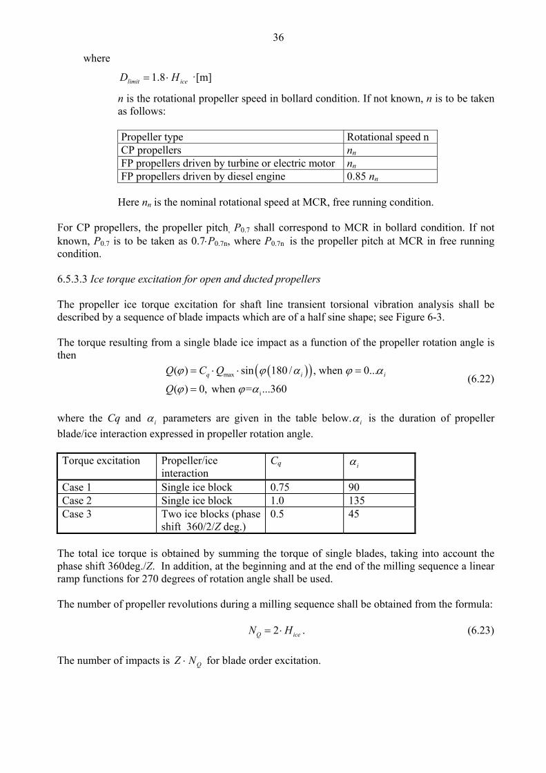
For CP propellers, the propeller pitch, P0.7 shall correspond to MCR in bollard condition. If not known, P0.7 is to be taken as 0.7P0.7n, where P0.7n is the propeller pitch at MCR in free running condition. 6.5.3.3 Ice torque excitation for open and ducted propellers The propeller ice torque excitation for shaft line transient torsional vibration analysis shall be described by a sequence of blade impacts which are of a half sine shape; see Figure 6-3. The torque resulting from a single blade ice impact as a function of the propeller rotation angle is then
max
i
( ) sin 180 / , when 0...
( ) 0, when = ...360
q i iQ C Q
Q
(6.22)
where the Cq and i parameters are given in the table below. i is the duration of propeller
blade/ice interaction expressed in propeller rotation angle. Torque excitation Propeller/ice
interaction Cq i
Case 1 Single ice block 0.75 90 Case 2 Single ice block 1.0 135 Case 3 Two ice blocks (phase
shift 360/2/Z deg.) 0.5 45
The total ice torque is obtained by summing the torque of single blades, taking into account the phase shift 360deg./Z. In addition, at the beginning and at the end of the milling sequence a linear ramp functions for 270 degrees of rotation angle shall be used. The number of propeller revolutions during a milling sequence shall be obtained from the formula: 2Q iceN H . (6.23)
The number of impacts is QNZ for blade order excitation.

37
00,10,20,30,40,50,60,70,80,9
1
0 200 400 600 800 1000 1200 1400
Rotaion angle [deg]
Q/Q
max
00,10,20,30,40,50,60,70,80,9
1
0 200 400 600 800 1000 1200 1400
Rotation angle
Q/Q
max
0
0,10,2
0,3
0,4
0,50,6
0,7
0,80,9
1
0 200 400 600 800 1000 1200 1400
Rotation angle [deg]
Q/Q
max
Figure 6-3. The shape of the propeller ice torque excitation for 90, and 135 degree single-blade impact sequences and 45 degree double blade impact sequence. (Figures apply for propellers with 4 blades.) 6.5.3.4 Design torque along propeller shaft line If there is not any relevant first blade order torsional resonance within the designed operating rotational speed range extended 20% above the maximum and 20% below the minimum operating speeds, the following estimation of the maximum torque can be used.
max maxr et
IQ Q Q
I [kNm], (6.24)
where I is equivalent mass moment of inertia of all parts on engine side of component under consideration and It is equivalent mass moment of inertia of the whole propulsion system. All the torques and the inertia moments shall be reduced to the rotation speed of the component being examined. If the maximum torque, Qemax, is not known, it shall be taken as follows: Propeller type Qemax
Propellers driven by electric motor Qmotor
CP propellers not driven by electric motor Qn
FP propellers driven by turbine Qn FP propellers driven by diesel engine 0.75 Qn
Here Q motor is the electric motor peak torque. If there is a first blade order torsional resonance within the designed operating rotational speed range extended 20% above the maximum and 20% below the minimum operating speeds, the design torque (Qr) of the shaft component shall be determined by means of torsional vibration analysis of the propulsion line. 6.5.4 Blade failure load The ultimate load resulting from blade failure as a result of plastic bending around the blade root shall be calculated from the formula below. The ultimate load is acting on the blade at the 0.8R radius in the weakest direction of the blade. For calculation of the extreme spindle torque, the spindle arm is to be taken as 2/3 of the distance between the axis of blade rotation and the leading/trailing edge (whichever is the greater) at the 0.8R radius.
38
2300
0.8 2ref
ex
c tF
D r
[kN], (6.25)
where
uref 4.06.0 2.0
c, t, and r are, respectively, the length, thickness, and radius of the cylindrical root section of the blade at the weakest section outside the root filet.
6.6 Design
6.6.1 Design principle The strength of the propulsion line shall be designed according to the pyramid strength principle. This means that the loss of the propeller blade shall not cause any significant damage to other propeller shaft line components. 6.6.2 Propeller blade
6.6.2.1 Calculation of blade stresses
The blade stresses shall be calculated for the design loads given in section 6.5.1. Finite element analysis shall be used for stress analysis for final approval for all propellers. The following simplified formulae can be used in estimating the blade stresses for all propellers at the root area (r/R < 0.5). The root area dimensions based on formula (6.26) can be accepted even if the FEM analysis would show greater stresses at the root area.
1 2100BL
st
MC
ct
[MPa], (6.26)
where
constant C1 is the actual stress
stress obtained with beam equation. If the actual value is not available,
C1 should be taken as 1.6.
FRRr750M BL )/.( , for relative radius r/R < 0.5
F is the maximum of Fb and Ff, whichever is greater.
6.6.2.2 Acceptability criterion The following criterion for calculated blade stresses has to be fulfilled:
2 1.5ref
st
(6.27)
where

39
st is the calculated stress for the design loads. If FEM analysis is used in estimating the
stresses, von Mises stresses shall be used
2ref is the reference stress, defined as:
uref 7.02 or
uref 4.06.0 2.02 , whichever is less.
6.6.2.3 Fatigue design of propeller blade The fatigue design of the propeller blade is based on an estimated load distribution for the service life of the ship and the S-N curve for the blade material. An equivalent stress that produces the same fatigue damage as the expected load distribution shall be calculated and the acceptability criterion for fatigue should be fulfilled as given in this section. The equivalent stress is normalised for 100 million cycles. If the following criterion is fulfilled fatigue calculations according to this chapter are not required: 32
exp 1 2 log( )BBref iceB N (6.28)
where B1, B2 and B3 coefficients for open and ducted propellers are given in the table below. Open propeller Ducted propeller B1 0.00270 0.00184 B2 1.007 1.007 B3 2.101 2.470
For calculation of equivalent stress two types of SN curves are available.
1. Two slope SN curve (slopes 4.5 and 10), see Figure 6-4. 2. One slope SN curve( the slope can be chosen), see Figure 6-5.
The type of the SN-curve shall be selected to correspond to the material properties of the blade. If the SN-curve is not known the two slope SN curve shall be used.
1,E+04 1,E+06 1,E+08 1,E+10
Number of loads
Str
ess
amp
litu
de
Slope 4.5
Slope 10
exp
1,E+04 1,E+06 1,E+08 1,E+10
Number of loads
Str
ess
amp
litu
de
Slope m=8
Slope m=10
exp
Figure 6-4. Two-slope S-N curve. Figure 6-5. Constant-slope S-N curve.
40
Equivalent fatigue stress The equivalent fatigue stress for 108 stress cycles which produces the same fatigue damage as the load distribution is: fat ice max
(6.29)
where
maxmaxmax 5.0 biceficeice
maxice is the mean value of the principal stress amplitudes resulting from design forward
and backward blade forces at the location being studied.
maxfice is the principal stress resulting from forward load
maxbice is the principal stress resulting from backward load
In calculation of (σice)max, case 1 and case 3 (or case 2 and case 4) are considered as a pair for (σice)fmax, and (σice)bmax calculations. Case 5 is excluded from the fatigue analysis.
Calculation of parameter for two-slope S-N curve The parameter relates the maximum ice load to the distribution of ice loads according to the regression formula
2 3 41 max
log( )C C C
ice fl iceC N (6.30)
where
exp mvfl ,
where
is the reduction factor for scatter and test specimen size effect
is the reduction factor for variable amplitude loading
m is the reduction factor for mean stress
exp is the mean fatigue strength of the blade material at 108 cycles to failure in
seawater. The following values should be used for the reduction factors if actual values are not available: = 0.67, = 0.75, and m = 0.75.
The coefficients 1C , 2C , 3C , and 4C are given in Table 6-6.
41
Table 6-6.
Open propeller Ducted propeller
1C 0.000711 0.000509
2C 0.0645 0.0533
3C -0.0565 -0.0459
4C 2.22 2.584
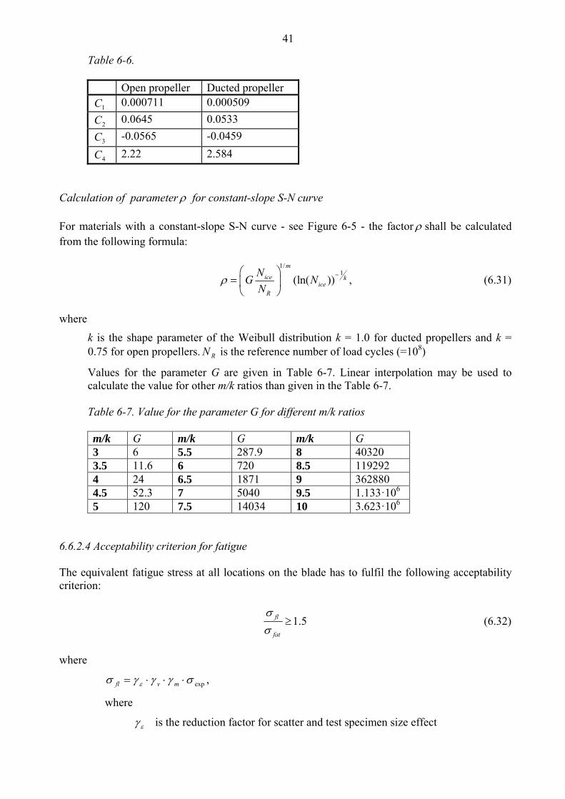
Calculation of parameter for constant-slope S-N curve For materials with a constant-slope S-N curve - see Figure 6-5 - the factor shall be calculated from the following formula:
1/
1(ln( ))
m
ice kice
R
NG N
N
, (6.31)
where
k is the shape parameter of the Weibull distribution k = 1.0 for ducted propellers and k = 0.75 for open propellers. RN is the reference number of load cycles (=108)
Values for the parameter G are given in Table 6-7. Linear interpolation may be used to calculate the value for other m/k ratios than given in the Table 6-7. Table 6-7. Value for the parameter G for different m/k ratios m/k G m/k G m/k G 3 6 5.5 287.9 8 40320 3.5 11.6 6 720 8.5 119292 4 24 6.5 1871 9 362880 4.5 52.3 7 5040 9.5 1.133·106 5 120 7.5 14034 10 3.623·106
6.6.2.4 Acceptability criterion for fatigue The equivalent fatigue stress at all locations on the blade has to fulfil the following acceptability criterion:
1.5fl
fat
(6.32)
where
exp mvfl ,
where
is the reduction factor for scatter and test specimen size effect
42
is the reduction factor for variable amplitude loading
m is the reduction factor for mean stress
exp is the mean fatigue strength of the blade material at 108 cycles to failure in
seawater. The following values should be used for the reduction factors if actual values are not available: = 0.67, = 0.75, and m = 0.75.
6.6.3 Propeller bossing and CP mechanism The blade bolts, the CP mechanism, the propeller boss, and the fitting of the propeller to the propeller shaft shall be designed to withstand the maximum and fatigue design loads, as defined in section 6.5. The safety factor against yielding shall be greater than 1.3 and that against fatigue greater than 1.5. In addition, the safety factor for loads resulting from loss of the propeller blade through plastic bending as defined in section 6.5.4 shall be greater than 1.0 against yielding. 6.6.4 Propulsion shaft line The shafts and shafting components, such as the thrust and stern tube bearings, couplings, flanges and sealings, shall be designed to withstand the propeller/ice interaction loads as given in section 6.5. The safety factor is to be at least 1.3.
6.6.4.1 Shafts and shafting components The ultimate load resulting from total blade failure as defined in section 6.5.4 should not cause yielding in shafts and shaft components. The loading shall consist of the combined axial, bending, and torsion loads, wherever this is significant. The minimum safety factor against yielding is to be 1.0 for bending and torsional stresses. 6.6.5 Azimuthing main propulsors In addition to the above requirements, special consideration shall be given to those loading cases which are extraordinary for propulsion units when compared with conventional propellers. The estimation of loading cases has to reflect the way of operation of the ship and the thrusters. In this respect, for example, the loads caused by the impacts of ice blocks on the propeller hub of a pulling propeller have to be considered. Furthermore, loads resulting from the thrusters operating at an oblique angle to the flow have to be considered. The steering mechanism, the fitting of the unit, and the body of the thruster shall be designed to withstand the loss of a blade without damage. The loss of a blade shall be considered for the propeller blade orientation which causes the maximum load on the component being studied. Typically, top-down blade orientation places the maximum bending loads on the thruster body. Azimuth thrusters shall also be designed for estimated loads caused by thruster body/ice interaction. The thruster body has to stand the loads obtained when the maximum ice blocks, which are given in section 6.3, strike the thruster body when the ship is at a typical ice operating speed. In addition, the design situation in which an ice sheet glides along the ship’s hull and presses against the thruster body should be considered. The thickness of the sheet should be taken as the thickness of the maximum ice block entering the propeller, as defined in section 6.3.

43
6.6.6 Vibrations
The propulsion system shall be designed in such a way that the complete dynamic system is free from harmful torsional, axial, and bending resonances at a 1-order blade frequency within the designed running speed range, extended by 20% above and below the maximum and minimum operating rotational speeds. If this condition cannot be fulfilled, a detailed vibration analysis has to be carried out in order to determine that the acceptable strength of the components can be achieved.
6.7 Alternative design procedure
6.7.1 Scope As an alternative to sections 6.5 and 6.6, a comprehensive design study may be carried out to the satisfaction of the Administration or the classification society. The study has to be based on ice conditions given for different ice classes in section 6.3. It has to include both fatigue and maximum load design calculations and fulfil the pyramid strength principle, as given in section 6.6.1. 6.7.2 Loading Loads on the propeller blade and propulsion system shall be based on an acceptable estimation of hydrodynamic and ice loads. 6.7.3 Design levels The analysis is to indicate that all components transmitting random (occasional) forces, excluding propeller blade, are not subjected to stress levels in excess of the yield stress of the component material, with a reasonable safety margin. Cumulative fatigue damage calculations are to indicate a reasonable safety factor. Due account is to be taken of material properties, stress raisers, and fatigue enhancements. Vibration analysis is to be carried out and is to indicate that the complete dynamic system is free from harmful torsional resonances resulting from propeller/ice interaction. 7 MISCELLANEOUS MACHINERY REQUIREMENTS 7.1 Starting arrangements The capacity of the air receivers shall be sufficient to provide without reloading not less than 12 consecutive starts of the propulsion engine, if this has to be reversed for going astern, or 6 consecutive starts if the propulsion engine does not have to be reversed for going astern. If the air receivers serve any other purposes than starting the propulsion engine, they shall have additional capacity sufficient for these purposes. The capacity of the air compressors shall be sufficient for charging the air receivers from atmo-spheric to full pressure in one (1) hour, except for a ship with the ice class IA Super, if its pro-pulsion engine has to be reversed for going astern, in which case the compressor shall be able to charge the receivers in half an hour.

44
7.2 Sea inlet and cooling water systems The cooling water system shall be designed to ensure supply of cooling water when navigating in ice. For this purpose at least one cooling water inlet chest shall be arranged as follows:
1. The sea inlet shall be situated near the centreline of the ship and well aft if possible.
2. As guidance for design the volume of the chest shall be about one cubic metre for every 750 kW engine output of the ship including the output of auxiliary engines necessary for the ship's service.
3. The chest shall be sufficiently high to allow ice to accumulate above the inlet pipe.
4. A pipe for discharge cooling water, allowing full capacity discharge, shall be connected to the chest.
5. The open area of the strainer plates shall not be less than four (4) times the inlet pipe sectional area.
If there are difficulties to meet the requirements of paragraphs 2 and 3 above, two smaller chests may be arranged for alternating intake and discharge of cooling water. Otherwise the arrangement and situation shall be as above. Heating coils may be installed in the upper part of the sea chest. Arrangements for using ballast water for cooling purposes may be useful as a reserve in ballast condition but cannot be accepted as a substitute for sea a inlet chest as described above.
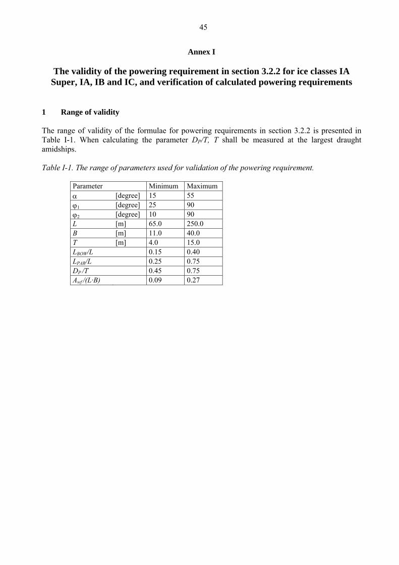
45
Annex I
The validity of the powering requirement in section 3.2.2 for ice classes IA
Super, IA, IB and IC, and verification of calculated powering requirements 1 Range of validity The range of validity of the formulae for powering requirements in section 3.2.2 is presented in Table I-1. When calculating the parameter DP/T, T shall be measured at the largest draught amidships. Table I-1. The range of parameters used for validation of the powering requirement.
Parameter Minimum Maximum [degree] 15 55 1 [degree] 25 90 2 [degree] 10 90 L [m] 65.0 250.0 B [m] 11.0 40.0 T [m] 4.0 15.0 LBOW/L 0.15 0.40 LPAR/L 0.25 0.75 DP /T 0.45 0.75 Awf /(L·B) 0.09 0.27

46
2 Verification of calculated powering requirements To check the results of calculated powering requirements, Table I-2 is presented with input data for a number of sample ships. Table I-2. Parameters and calculated minimum engine power of sample ships. Sample ship No. #1 #2 #3 #4 #5 #6 #7 #8 #9 Ice class IAS IA IB IC IAS IAS IA IA IB
degree 24 24 24 24 24 24 36 20 24
1 degree 90 90 90 90 30 90 30 30 90
2 degree 30 30 30 30 30 30 30 30 30 L m 150 150 150 150 150 150 150 150 150 B m 25 25 25 25 25 22 25 25 25 T m 9 9 9 9 9 9 9 9 9 LBOW m 45 45 45 45 45 45 45 45 45 LPAR m 70 70 70 70 70 70 70 70 70 Awf m2 500 500 500 500 500 500 500 500 500 DP m 5 5 5 5 5 5 5 5 5 Prop. No / type 1/CP 1/CP 1/CP 1/CP 1/CP 1/CP 1/CP 1/CP 1/FP New ships kW 7840 4941 3478 2253 6799 6406 5343 5017 3872 (see section 3.2.2) Existing ships kW 9192 6614 8466 7645 6614 6614 (calculated according to the formula in 3.2.4)
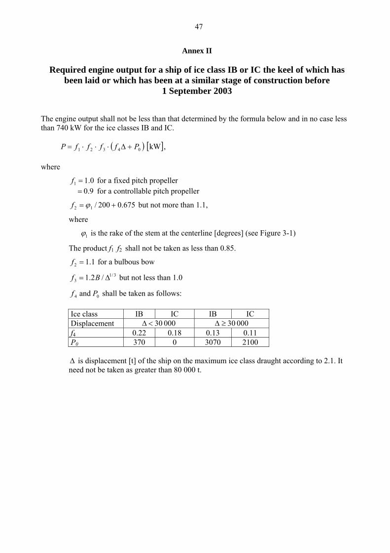
47
Annex II
Required engine output for a ship of ice class IB or IC the keel of which has
been laid or which has been at a similar stage of construction before 1 September 2003
The engine output shall not be less than that determined by the formula below and in no case less than 740 kW for the ice classes IB and IC.
kW 04321 PffffP ,
where
0.11 f for a fixed pitch propeller 0.9 for a controllable pitch propeller
675.0200/12 f but not more than 1.1,
where
1 is the rake of the stem at the centerline [degrees] (see Figure 3-1)
The product f1 f2 shall not be taken as less than 0.85.
1.12 f for a bulbous bow
3/13 /2.1 Bf but not less than 1.0
04 and Pf shall be taken as follows:
Ice class IB IC IB IC Displacement 000 30 000 30 f4 0.22 0.18 0.13 0.11 P0 370 0 3070 2100
is displacement [t] of the ship on the maximum ice class draught according to 2.1. It need not be taken as greater than 80 000 t.

48
Annex III
Ice class draught marking
Subject to section 2.2, the ship's sides are to be provided with a warning triangle and with a draught mark at the maximum permissible ice class draught amidships (see Figure III-1). The purpose of the warning triangle is to provide information on the draught limitation of the vessel when it is sailing in ice for masters of icebreakers and for inspection personnel in ports.
Figure III-1. Ice Class Draught Marking
Notes to Figure III-1
1. The upper edge of the warning triangle is to be located vertically above the “ICE” mark, 1000 mm higher than the Summer Load Line in fresh water but in no case higher than the deck line. The sides of the triangle are to be 300 mm in length.
2. The ice class draught mark is to be located 540 mm abaft the centre of the load line ring or 540 mm abaft the vertical line of the timber load line mark, if applicable.
3. The marks and figures are to be cut out of 5 - 8 mm plate and then welded to the ship's side. The marks and figures are to be painted in a red or yellow reflecting colour in order to make the marks and figures plainly visible even in ice conditions.
4. The dimensions of all letters are to be the same as those used in the load line mark.