Embed Size (px)
Citation preview
JSC 27301F
Verify correct version before use
Materials and Processes Selection, Control, and Implementation Plan for JSC Flight Hardware ______________________________ Engineering Directorate Structural Engineering Division August 2009
National Aeronautics and Space Administration Lyndon B. Johnson Space Center

JSC 27301F
Verify correct version before use
ii
PREFACE This Materials and Processes Selection, Control, and Implementation Plan defines the implementation of the materials and processes (M&P) requirements for all new flight hardware developed by the NASA Johnson Space Center (JSC). Space Shuttle GFE, International Space Station GFE, Constellation Program GFE, and JSC-developed payload hardware are to be designed and manufactured in accordance with this plan. The plan describes the implementation of the M&P requirements in NASA-STD-6016, Standard Materials and Processes Requirements for Spacecraft; SSP 30233, Space Station Requirements for Materials and Processes; SE-R-0006, General Specification Space Shuttle System Requirements for Materials and Processes; and JPR 8080.5A, JSC Design and Procedural Standards. This plan defines the responsibilities of the JSC Materials & Processes Branch and JSC contractors for flight hardware M&P requirements implementation and verification, and includes modifications of Space Shuttle, ISS, and Constellation Program requirements for flight hardware. The contents of this document are consistent with the tasks performed for the ISS as defined in SSP 41000, System Specification for the International Space Station. This flight hardware Materials and Processes Selection, Control, and Implementation Plan shall be implemented on all new contracts for the procurement of JSC flight hardware, and shall be included in existing contracts through contract changes. This document is under the control of the JSC Structural Engineering Division (JSC Code ES), and any changes or revisions shall be approved by the same organization.

JSC 27301F
Verify correct version before use
iii
MATERIALS AND PROCESSES SELECTION, CONTROL, AND IMPLEMENTATION PLAN FOR JSC FLIGHT HARDWARE Signature on File
Prepared By: ES4/Michael D. Pedley
Signature on File .
Signature on File Approved By: ES4 /Bradley S. Files
Signature on File .
Chief, Materials and Processes Branch

JSC 27301F
Verify correct version before use
iv
REVISIONS VERSION CHANGES DATE Baseline Original version (Materials Control Plan for JSC Space
station Government-Furnished Equipment) 3/96
A Retitled and revised to address all JSC flight hardware; numerous minor technical revisions, including reference document updates
7/16/99
B Added requirement for oxygen system hardware exposure to pressurized oxygen before flight (Section 5.1.4.1)
3/9/00
C Added ISS alcohol usage control (VUAs); added requirements for precision-cleaned hardware; revised author; incorporated administrative changes for division reorganization; numerous minor technical revisions, including reference document updates
1/29/02
D Clarified requirement on low earth orbit environment survivability (Section 5.3.7); added related requirement on external use of silver-plated fasteners (Section 5.6.5.2)
2/26/02
E Revised and retitled document to make compliant with JSC 49774A, Standard Manned Spacecraft Requirements for Materials and Processes
11/05
F Revised document to make compliant with NASA-STD-6016, Standard Materials and Processes Requirements for Spacecraft. NASA-STD-6016 replaces JSC 49774A, which is cancelled.
8/09

JSC 27301F
Verify correct version before use v
TABLE OF CONTENTS SECTION PAGE 1.0 INTRODUCTION 1 - 1 1.1 SCOPE 1 - 2 2.0 DOCUMENTS 2 - 1 2.1 APPLICABLE DOCUMENTS 2 - 1 2.1.1 VOLUNTARY CONSENSUS STANDARDS 2 - 1 2.1.2 GOVERNMENT AND MILITARY STANDARDS 2 - 4 2.1.3 NATIONAL AERONAUTICS AND SPACE ADMINISTRATION 2 - 5 2.1.4 JOHNSON SPACE CENTER / SPACE STATION PROGRAM 2 - 7 2.1.5 MARSHALL SPACE FLIGHT CENTER 2 - 8 2.1.6 JOHNSON SPACE CENTER MATERIALS AND PROCESSES 2 - 9 BRANCH 2.2 REFERENCE DOCUMENTS 2 - 11 3.0 REQUIREMENTS IMPLEMENTATION RESPONSIBILITIES 3 - 1 3.1 PLAN AND NON-PLAN CONTRACTORS 3 - 1 3.1.1 PLAN CONTRACTOR 3 - 1 3.1.2 NON-PLAN CONTRACTOR 3 - 1 3.2 NEW FLIGHT HARDWARE 3 - 1 3.2.1 JSC PLAN CONTRACTOR FLIGHT HARDWARE 3 - 2 3.2.2 JSC NON-PLAN CONTRACTOR FLIGHT HARDWARE 3 - 2 (& FLIGHT HARDWARE DESIGNED BY JSC EMPLOYEES) 3.3 MATERIALS AND PROCESSES RECIPROCAL AGREEMENTS 3 - 4 3.4 PREVIOUSLY CERTIFIED GFE FOR ISS AND CONSTELLATION 3 - 4

JSC 27301F
Verify correct version before use
vi
3.5 ISS GFE AS ORION CARGO 3 - 5 4.0 GENERAL REQUIREMENTS 4 - 1 4.1 MATERIALS AND PROCESSES SELECTION, CONTROL, AND
IMPLEMENTATION PLAN 4 - 2 4.1.1 COORDINATION, APPROVAL, AND TRACKING 4 - 2 4.1.2 APPROVAL SIGNATURE 4 - 2 4.1.3 MATERIALS AND PROCESSES CONTROLS 4 – 3 4.1.3.1 Standard and Specification Obsolescence 4 – 4 4.1.3.2 Commercial Off-The-Shelf (COTS) Hardware 4 - 5 4.2 MATERIALS AND PROCESS USAGE DOCUMENTATION 4 - 5 4.2.1 MIUL CONTENT 4 - 6 4.3 MATERIALS USAGE AGREEMENTS 4 - 7 4.3.1 CATEGORY I MUAs 4 - 8 4.3.2 CATEGORY II MUAs 4 - 8 4.3.3 CATEGORY III MUAs 4 - 8 4.4 VOLATILE ORGANIC COMPOUND USAGE AGREEMENTS 4 - 8 4.4.1 CATEGORY I VUAs 4 - 9 4.4.2 CATEGORY II VUAs 4 - 9 4.4.3 VOLATILE ORGANIC COMPOUND USAGE AGREEMENT
SUBMITTAL 4 - 9 4.5 MANUFACTURING PLANNING 4 - 10 4.6 MATERIALS CERTIFICATION AND TRACEABILITY 4 - 10 4.7 MATERIALS DESIGN ALLOWABLES 4 - 11 4.7.1 ALLOWABLES REQUIREMENTS 4 – 11

JSC 27301F
Verify correct version before use
vii
4.7.2 ALLOWABLES IMPLEMENTATION IN DESIGN 4 - 12 4.7.3 STRUCTURAL FASTENER ALLOWABLE PROPERTIES 4 - 12 4.8 MATERIALS AND FRACTURE CONTROL CERTIFICATION 4 - 13 PROCESS 4.8.1 M&P DRAWING APPROVAL 4 - 14 4.8.2 CERTIFICATION OF NEW FLIGHT HARDWARE 4 - 14 4.8.3 CERTIFICATION OF MODIFIED FLIGHT HARDWARE 4 - 14 4.8.4 CERTIFICATION OF OFF-THE-SHELF (OTS) HARDWARE 4 - 15 5.0 DETAILED REQUIREMENTS 5 - 1 5.1 FLAMMABILITY, OFFGASSING, AND COMPATIBILITY 5 - 1 REQUIREMENTS 5.1.1 FLAMMABILITY CONTROL 5 - 1 5.1.1.1 Stowed Flammable Hardware 5 - 2 5.1.1.2 Spacing of Hook and Loop Fasteners 5 - 2 5.1.2 TOXIC OFFGASSING 5 - 3 5.1.2.1 Personal Hygiene Kit (PHK) Materials 5 - 3 5.1.2.2 Medical Materials 5 - 3 5.1.3 FLUID COMPATIBILITY (FLUIDS OTHER THAN OXYGEN) 5 - 4 5.1.4 OXYGEN COMPATIBILITY 5 - 5 5.1.4.1 Oxygen Component Acceptance Test 5 - 6 5.1.5 HYDROGEN COMPATIBILITY 5 - 7 5.1.6 ELECTRICAL WIRE INSULATION MATERIALS 5 - 7 5.2 METALS 5 - 8 5.2.1 ALUMINUM 5 - 8

JSC 27301F
Verify correct version before use
viii
5.2.2 STEEL 5 - 8 5.2.2.1 Heat Treatment of Steels 5 - 8 5.2.2.2 Drilling and Grinding of High Strength Steel 5 - 9 5.2.2.3 Corrosion Resistant Steel 5 - 9 5.2.3 TITANIUM 5 - 10 5.2.3.1 Heat Treatment 5 - 10 5.2.3.2 Titanium Contamination 5 - 10 5.2.3.3 Titanium Wear 5 - 10 5.2.3.4 Titanium Welding 5 - 11 5.2.3.5 Titanium Flammability 5 - 11 5.2.4 MAGNESIUM 5 - 11 5.2.5 BERYLLIUM 5 - 12 5.2.6 CADMIUM 5 - 12 5.2.7 MERCURY 5 - 12 5.2.8 REFRACTORY METALS 5 - 13 5.2.9 SUPERALLOYS (NICKEL AND COBALT BASED) 5 - 13 5.2.9.1 Heat Treatment of Nickel- and Cobalt-Based Alloys 5 - 13 5.2.10 TIN 5 - 14 5.3 NONMETALLIC MATERIALS 5 - 14 5.3.1 ELASTOMERIC MATERIALS 5 - 14 5.3.2 POLYVINYL CHLORIDE 5 - 14 5.3.3 COMPOSITE MATERIALS 5 - 14 5.3.4 LUBRICANTS 5 - 15

JSC 27301F
Verify correct version before use
ix
5.3.5 LIMITED LIFE ITEMS 5 - 15 5.3.6 VACUUM OUTGASSING 5 - 16 5.3.7 EXTERNAL ENVIRONMENT SURVIVABILITY 5 - 17 5.3.8 MOISTURE AND FUNGUS RESISTANCE 5 - 18 5.3.9 GLYCOLS 5 - 19 5.3.10 ETCHING FLUOROCARBONS 5 - 19 5.3.11 WATER-SOLUBLE VOLATILE ORGANIC COMPOUNDS 5 - 19 5.4 PROCESSES 5 - 20 5.4.1 FORGING 5 - 20 5.4.2 CASTINGS 5 - 21 5.4.3 ADHESIVE BONDING 5 - 21 5.4.4 WELDING 5 - 22 5.4.4.1 Weld Repair 5 - 22 5.4.4.2 Weld Filler Metal 5 - 22 5.4.4.3 Aluminum Welding 5 - 23 5.4.4.4 Welding of Steel Alloys 5 - 23 5.4.4.5 Welding of Titanium Alloys 5 - 23 5.4.4.6 Low Stress Welds and Structures 5 - 23 5.4.5 BRAZING 5 - 23 5.4.6 STRUCTURAL SOLDERING 5 - 24 5.4.7 ELECTRICAL DISCHARGE MACHINING AND LASER 5 - 24
MACHINING 5.4.8 NICKEL PLATING 5 - 25 5.4.9 PRECISION CLEAN HARDWARE 5 - 25

JSC 27301F
Verify correct version before use x
5.4.9.1 Assembly, Cleaning, Flushing, and Testing Fluids 5 - 25 5.4.9.2 Personnel Training 5 - 25 5.4.9.3 Welding Precision-Cleaned Hardware (Including Tube Preparation) 5 - 26 5.4.9.4 Ground Support Equipment (GSE) Interfaces 5 - 27 5.4.9.5 Convoluted Flex Hoses 5 - 28 5.4.9.6 Maintaining System Cleanliness 5 - 28 5.4.9.7 Sampling For Residual Solvents Incompatible With Fluid Systems 5 - 29 5.5 MATERIAL NONDESTRUCTIVE INSPECTION 5 - 29 5.5.1 NONDESTRUCTIVE EVALUATION (NDE) PLAN 5 - 29 5.5.2 NDE ETCHING 5 - 30 5.6 SPECIAL MATERIALS REQUIREMENTS 5 - 30 5.6.1 RESIDUAL STRESSES 5 - 30 5.6.2 SANDWICH ASSEMBLIES 5 - 31 5.6.3 STRESS CORROSION CRACKING 5 - 31 5.6.4 CORROSION PREVENTION AND CONTROL 5 - 31 5.6.4.1 Steel 5 - 33 5.6.4.2 Sealing 5 - 33 5.6.5 HYDROGEN EMBRITTLEMENT 5 - 33 5.6.6 FASTENER INSTALLATION 5 - 33 5.6.6.1 Fastener Locking Requirements 5 - 34 5.6.6.2 Silver-Plated Fasteners 5 - 34 5.6.7 CLEANLINESS CONTROL 5 - 35 5.6.7.1 Packaging 5 - 35

JSC 27301F
Verify correct version before use
xi
5.7 MATERIAL AND PROCESSES FOR ELECTRICAL COMPONENTS 5 - 35 5.7.1 ELECTRICAL BONDING AND GROUNDING 5 - 35 5.7.2 USE OF SILVER 5 - 36 5.7.3 WIRE/CABLE ASSEMBLIES 5 - 36 5.7.4 FIBER OPTICS 5 - 36 5.7.5 PRINTED WIRING BOARDS 5 - 36 5.7.6 PRINTED WIRING ASSEMBLIES 5 - 36 5.7.6.1 Staking/Conformal Coating 5 - 36 5.7.6.2 Other Processes 5 - 37 5.7.7 ELECTRICAL SOLDERING 5 - 37 5.7.8 ELECTRICAL CRIMPING 5 - 37 5.7.9 ELECTRICAL WIRE WRAPPED CONNECTIONS 5 - 37 5.7.10 ELECTROSTATIC DISCHARGE CONTROL 5 - 37 6.0 REVIEWS AND VERIFICATION 6 - 1 6.1 REVIEWS 6 – 1 6.2 VERIFICATION 6 - 1
JSC 27301F
Verify correct version before use
xii
APPENDICES APPENDIX PAGE A ABBREVIATIONS AND ACRONYMS A - 1 B DEFINITIONS B - 1 C JSC MATERIALS AND FRACTURE CONTROL C - 1 CERTIFICATION FORM D JSC MATERIALS USAGE AGREEMENT FORM and D - 1 JSC VOLATILE USAGE AGREEMENT FORM E CATEGORY III MUA RATIONALE CODES E - 1 F EXCEPTIONS TO NASA-STD-6016 F - 1

JSC 27301F
Verify correct version before use
1-1
1.0
INTRODUCTION
This plan documents the methods by which the NASA Johnson Space Center (JSC) will implement materials and processes control for flight hardware developed by JSC, including International Space Station GFE, Space Shuttle GFE, Constellation Program GFE (including GFE for the Orion Crew Exploration Vehicle), and payload hardware. The plan addresses the detailed requirements in NASA-STD-6016, Standard Materials and Processes Requirements for Spacecraft. The plan does not apply to program hardware developed by a program contractor as contractor-furnished equipment (CFE). Note: Several NASA Marshall Space Flight Center (MSFC) specifications imposed by NASA-STD-6016 contain language requiring approval by MSFC M&P. In all such cases, the approval authority for flight hardware developed by JSC is JSC M&P, not MSFC. This plan also implements for JSC flight hardware the Materials and Processes (M&P) requirements contained in SSP 30233, Space Station Requirements for Materials and Processes and SE-R-0006, General Specification Space Shuttle System Requirements for Materials and Processes. The M&P requirements for Constellation Program hardware are contained in NASA-STD-(I)-6016, which has been replaced by NASA-STD-6016; compliance with NASA-STD-6016 ensures compliance with Constellation Program M&P requirements. The plan tailors the requirements in NASA-STD-6016, SSP 30233, and SE-R-0006 for JSC in-house hardware; in the event of a conflict between these three documents and this implementation plan, this plan takes precedence. Note: Exceptions to NASA-STD-6016 are identified in Appendix F.
a. Flight hardware under JSC control shall be designed and fabricated in accordance with this plan.
b. This plan shall be incorporated as a general materials control specification in end-item
specifications for JSC flight hardware procurements.
c. This plan shall be implemented on all new contracts for procurement of JSC flight hardware, and shall be included in existing contracts through contract changes.
d. Ground Support Equipment (GSE) supplied as JSC-controlled hardware shall comply
with this plan where GSE hardware can adversely affect flight hardware.
Note: This plan does not address fracture control. Fracture control for JSC flight hardware structures, including pressure vessels, is implemented in accordance with JSC 25863B, Fracture Control Plan for JSC Flight Hardware. However, the Materials and Fracture Control Certification generated to verify compliance with this plan (see Section 4.6) includes certification of compliance with fracture control requirements and any flight limitations determined by the fracture control analysis. The JSC Materials & Processes Branch monitors and reviews the fracture control program and evaluates the fracture control analysis.

JSC 27301F
Verify correct version before use
2-1
2.0
DOCUMENTS
The following documents include specifications, standards, handbooks, and other special publications. They are applicable to the extent specified herein. In the event of a conflict between these documents and this plan, this plan shall take precedence. 2.1 APPLICABLE DOCUMENTS 2.1.1 VOLUNTARY CONSENSUS STANDARDS DOCUMENT NO. TITLE ANSI/IPC-J-STD-001C Requirements for soldered electrical and electronic assemblies References 5.7.6.2, 5.7.8 ASTM-E595-93 Total Mass Loss and Collected Volatile Condensable Materials
From Outgassing In A Vacuum Environment Reference 5.3.7 AWS C3.2M/C3.2:2008 Standard Method for Evaluating the Strength of Brazed Joints Reference 5.4.5 AWS C3.3:2008 Recommended Practices for the Design, Manufacture, and
Inspection of Critical Brazed Components, Reference 5.4.5 AWS C3.4M/C3.4:2007 Specification for Torch Brazing Reference 5.4.5 AWS C3.5M/C3.5:2007 Specification for Induction Brazing Reference 5.4.5 AWS C3.6M/C3.6:2008 Specification for Furnace Brazing Reference 5.4.5

JSC 27301F
Verify correct version before use
2-2
AWS C3.7M/C3.7:2005 Specification for Aluminum Brazing Reference 5.3.5 AWS D17.1:2001 Specification for Fusion Welding for Aerospace Applications Reference 5.4.4 EOS/ESD S20.20 (2007) Development of an Electrostatic Discharge Control Program:
Protection of Electrical and Electronic Parts, Assemblies and Equipment (Excluding Electrically Initiated Explosive Devices)
Reference 5.7.11 IPC-CM-770E (2004) Component Mounting Guidelines For Printed Boards. Reference 5.7.6.2 IPC-2221A (2003) Generic Standard on Printed Board Design Reference 5.7.5 IPC-2222 (1998) Sectional Design Standard for Rigid Organic Printed Boards Reference 5.7.5 IPC-6011 (1996) Generic Performance Specification for Printed Boards Reference 5.7.5 IPC-6012B (2004) Quality and Performance Specification for Rigid Printed Boards (Inc. Amendment 2 (2008)) Reference 5.7.5 NAS 410 (2008) NAS Certification and Qualification of Nondestructive Test Personnel Reference 5.5.1 NAS 412 (1997) Foreign Object Damage/Foreign Object Debris (FOD) Prevention Reference 5.6.6

JSC 27301F
Verify correct version before use
2-3
SAE-AMS-H-6875A Heat Treatment Of Steel Raw Materials (1998, Reaffirmed 2006) Reference 5.2.2.1 SAE-AMS-STD-401 Sandwich Constructions and Core Materials; General Test (1999) Methods Reference 5.6.2 SAE-AMS 2175 (2003) Castings, Classification and Inspection Of Reference 5.4.2 SAE-AMS 2375D (2007) Control of Forgings Requiring First Article Approval Reference 5.4.1 SAE-AMS 2403L (2004) Plating, Nickel General Purpose Reference 5.4.8 SAE-AMS 2404E (2003) Plating, Electroless Nickel Reference 5.4.8 SAE-AMS 2423D Plating, Nickel Hard Deposit (2002, Reaffirmed 2007) Reference 5.4.8 SAE-AMS 2488D Anodic Treatment - Titanium & Titanium Alloys, Solution pH 13 (2003, Reaffirmed 2006) or Higher Reference 5.2.3.3 SAE-AMS 2491D Surface Treatment, Polytetrafluoroethylene, Preparation for (1989, Reaffirmed 2003) Bonding Reference 5.7.7 SAE-AMS 2759D (2006) Heat Treatment of Steel Parts, General Requirements Reference 5.2.2.1

JSC 27301F
Verify correct version before use
2-4
SAE-AMS 2759/9C (2007) Hydrogen Embrittlement Relief (Baking) of Steel Parts Reference 5.2.2.1 SAE-AMS 2770H (2006) Heat Treatment of Wrought Aluminum Alloy Parts Reference 5.2.1 SAE-AMS 2771C (2004) Heat Treatment of Aluminum Alloy Castings Reference 5.2.1 SAE-AMS 2772E (2008) Heat Treatment of Aluminum Alloy Raw Materials Reference 5.2.1 SAE-AMS 2774B (2008) Heat Treatment, Wrought Nickel Alloy and Cobalt Alloy Parts Reference 5.2.9.1 SAE-AMS-H-81200A Heat Treatment of Titanium and Titanium Alloys. (2003) Reference 5.2.3.1 SAE-AS7928A (2008) Terminals, Lug: Splices, Conductors: Crimp Style, Copper,
General Specification For Reference 5.7.9 2.1.2 GOVERNMENT AND MILITARY STANDARDS DOCUMENT NO. TITLE DOT/FAA/AR-MMPDS-04 Metallic Materials Properties Development and Standardization
(MMPDS) Reference 4.5, 5.3.4 MIL-HDBK-17-1F (2002) Volume 1. Polymer Matrix Composites Guidelines for
Characterization of Structural Materials Reference 4.5 MIL-HDBK-17-2F (2002) Composite Materials Handbook Volume 2. Polymer Matrix Composites Materials Properties Reference 4.5

JSC 27301F
Verify correct version before use
2-5
MIL-HDBK-17-3F (2002) Volume 3. Polymer Matrix Composites Materials Usage, Design, and Analysis Reference 4.5 MIL-HDBK-17-4A (2002) Composite Materials Handbook Volume 4. Metal Matrix Composites Reference 4.5 MIL-HDBK-17-5 (2002) Volume 5. Ceramic Matrix Composites Reference 4.5 MIL-HDBK-6870A (2001) Inspection Program Requirements, Nondestructive for Aircraft and
Missile Materials and Parts Reference 5.5.1 MIL-PRF-31032A (2006) Printed Circuit Board/Printed Wiring Board, General Specification (Inc. Supplement 1 (2008)) for Reference 5.6.5 MIL-HDBK-454B (2007) General Guidelines for Electronic Equipment Reference 5.3.9 MIL-STD-810F (2000) Department of Defense Test Method Standard for Environmental Change Notice 3 (2003) Engineering Considerations and Laboratory Tests Reference 5.3.9 MIL-STD-889B (1976) Dissimilar Metals (Change Notice 3 (1993)) Reference 5.6.4 2.1.3 NATIONAL AERONAUTICS AND SPACE ADMINISTRATION DOCUMENT NO. TITLE CxP 70145 Constellation Program Contamination Control Requirements (Baseline Change 001 (2008)) Reference 5.4.9

JSC 27301F
Verify correct version before use
2-6
NASA-STD-5006 General Fusion Welding Requirements for Aerospace Materials Used in Flight Hardware
Reference 5.4.4 NASA-STD-5009 Nondestructive Evaluation Requirements for Fracture-Critical
Metallic Components Reference 5.5.1 NASA-STD-(I)-6001A Flammability, Offgassing, and Compatibility Requirements and Test Procedures References 5.1, 5.1.1, 5.1.2, 5.1.3, 5.1.4, 5.1.5 NASA-STD-6016 Standard Materials and Processes Requirements for Spacecraft References 1.0, 3.1.1, 3.5, Appendix F NASA-STD-6008 NASA Fastener Procurement, Receiving Inspection, and Storage
Practices for Spaceflight Hardware Reference 5.6.6 NSTS 1700.7B Safety Policy and Requirements for Payloads Using the Space (including ISS Addendum) Transportation System References 3.4, 5.1.3 NASA-TM-86556 Lubrication Handbook For the Space Industry, Part A: Solid
Lubricants, Part B: Liquid Lubricants Reference 5.3.5 NASA-STD-8739.4 Crimping, Interconnecting Cables, Harnesses, and Wiring References 5.7.3, 5.7.9, 5.7.10 NASA-STD-8739.5 Fiber Optic Terminations, Cable Assemblies, and Installation References 5.7.4 NASA-STD-8739.1 Workmanship Standard for Surface Mount Technology References 5.7.6.1

JSC 27301F
Verify correct version before use
2-7
NASA-STD-8739.2 Requirement for Conformal Coating and Staking of Printed Wiring Boards and Electronic Assemblies
References 5.7.6.1, 5.7.6.2 2.1.4 JOHNSON SPACE CENTER / SPACE STATION PROGRAM The latest revision of all JSC documents shall be used unless a specific release is identified in this section. DOCUMENT NO. TITLE JSC 20584 Spacecraft Maximum Allowable Concentrations for Airborne
Contaminants Reference 5.1.2 JSC 25863 Fracture Control Plan for JSC Flight Hardware Reference 1.0 JPR 8080.5 JSC Design and Procedural Standards Manual References 1.0 and 6.0 JPR 8500.4 Engineering Drawing System Manual: Drawing Format,
Requirements, and Procedures References 3.0, 4.2 SE-R-0006D Space Shuttle Program Requirements for Materials and Processes References 3.1.1, 3.4 SSP 30233G Space Station Requirements for Materials and Processes Reference 3.1.1 SSP 30234F Instructions for Preparation of Failure Modes and Effects Analysis
and Critical Items List for Space Station References 3.2.1, 3.2.2 SSP 30426D Space Station External Contamination Control Requirements Reference 5.3.7

JSC 27301F
Verify correct version before use
2-8
SSP 50431A Space Station Program Requirements for Payloads Reference 3.2.1 2.1.5 MARSHALL SPACE FLIGHT CENTER DOCUMENT NO. TITLE MSFC-SPEC-250A (1977) Protective Finishes for Space Vehicle Structures and Associated
Flight Equipment, General Specification for Reference 5.6.4 MSFC-SPEC-445A (1990) Adhesive Bonding, Process and Inspection, Requirements for Reference 5.4.3 MSFC-SPEC-504C (1990) Welding, Aluminum Alloys References 5.4.4.3, 5.4.4.5 MSFC-STD-3029A (2005) Guidelines for Selection of Metallic Materials for Stress- (formerly Corrosion-Cracking Resistance in Sodium Chloride MSFC-SPEC-522B) Environments Reference 5.6.3 MSFC-SPEC-560A (1988) The Fusion Welding of Steels, Corrosion and Heat Resistant
Alloys Reference 5.4.4.4 MSFC-STD-557A (2005) Threaded Fasteners, 6 Al-4V Titanium Alloy, Usage Criteria for
Spacecraft Applications Reference 5.6.5 MSFC-SPEC-766 (1982) Specification: Fusion Welding Titanium and Titanium Alloys Reference 5.4.4.5 MSFC-PROC-404A (1989) Procedure: Gases Drying and Preservation, Cleanliness Level and
Inspection Methods Reference 5.1.4.1

JSC 27301F
Verify correct version before use
2-9
2.1.6 JOHNSON SPACE CENTER MATERIALS AND PROCESSES BRANCH The latest revision of all JSC Materials and processes Branch documents shall be used. PRC-0001 Manual Arc Welding of Aluminum Alloy Flight Hardware Reference 5.4.4.3 PRC-0002 Manual Arc Welding of Titanium Alloy Flight Hardware, Process
Specification for Reference 5.4.4.5 PRC-0005 Manual Arc Welding of Steel and Nickel Alloy Flight Hardware Reference 5.4.4.4 PRC-0008 Qualification of Manual Arc Welders, Process Specification for Reference 5.4.4.5 PRC-0010 Automatic and Machine Arc Welding of Steel and Nickel Alloy
Hardware Reference 5.4.4.4 PRC-1001 Adhesive Bonding Reference 5.4.3 PRC-2003 Heat Treatment of Nickel Alloys Reference 5.2.9.1 PRC-5001 Process Specification for Cleaning of Hardware References 5.4.9, 5.4.9.3 PRC-5002 Passivation and Pickling of Metallic Materials Reference 5.6.4.1 PRC-6001 Composite Laminate Prepreg. Parts, Process Specification for the
Manufacture of Reference 5.3.4

JSC 27301F
Verify correct version before use
2-10
PRC-6002 Sandwich Structures, Process Specification for the Assembly of Reference 5.3.4 PRC-6003 Trimming and Drilling of Composites, Process Specification for Reference 5.3.4 PRC-6501 Ultrasonic Inspection of Composites, Process Specification for the Reference 5.3.4, 5.5.1 PRC-6503 Radiographic Inspection Reference 5.5.1 PRC-6504 Ultrasonic Inspection of Wrought Metals Reference 5.5.1 PRC-6505 Magnetic Particle Inspection Reference 5.5.1 PRC-6506 Liquid Penetrant Inspection Reference 5.5.1 PRC-6509 Eddy Current Inspection Reference 5.5.1 PRC-6510 Process Specification for Ultrasonic Inspection of Welds Reference 5.5.1 PRC-7001 Soldering of Electrical Components Reference 5.7.8 PRC-7002 Staking and Conformal Coating of Printed Wiring Boards and
Electronic Assemblies References 5.7.6.1 and 5.7.6.2 PRC-7003 Electrical Cables, Wiring, and Harnesses

JSC 27301F
Verify correct version before use
2-11
Reference 5.7.3 PRC-7005 Printed Circuit Boards and Assemblies Reference 5.7.5 ES SOP-004.5 Control of Weld and Braze Filler Materials, Electrodes, and
Fluxing Materials Reference 5.4.4.2, 5.4.5 ES SOP-007.5 Materials and Processes Drawing Approval Reference 4.1.2, 4.6.1 ES SOP-007.6 Materials and Fracture Control Certification Reference 4.6 ES SOP 0009.86 Written Practice for Certification and Qualification of
Nondestructive Evaluation Personnel Reference 5.5.1 2.2 REFERENCE DOCUMENTS DOCUMENT NO. TITLE ASTM G63-99 Standard Guide for Evaluating Nonmetallic Materials for Oxygen
Service Reference 5.1.4 ASTM G88-90 Standard Guide for Designing Systems for Oxygen Service Reference 5.1.4 ASTM G94-92 Standard Guide for Evaluating Metals for Oxygen Service Reference 5.1.4 CxP 70165 (2008) Constellation Program Requirements for the Manufacture and
Inspection of Electrical/Electronic Assemblies for Aerospace and High Performance (AHP) Applications

JSC 27301F
Verify correct version before use
2-12
Reference 5.7 JSC 29353A Flammability Configuration Analysis for Spacecraft Applications Reference 5.1.1 GSFC Supplement Process Specification for Rigid Printed Boards for Space S-312-P003 Applications and Other High Reliability Uses, Reference 5.7.5

JSC 27301F
Verify correct version before use
3-1
3.0
REQUIREMENTS IMPLEMENTATION RESPONSIBILITIES
Primary responsibilities for implementing the requirements in this plan are divided between the JSC Materials & Processes Branch and JSC contractors as outlined in this section. These and other responsibilities are discussed in further detail in other sections of this document. JSC contractors are divided into in-house contractors that design and fabricate flight hardware at JSC, using the JSC engineering drawing release system per JPR 8500.4, and outside contractors that design and fabricate flight hardware for JSC in accordance with a contractor drawing release system 3.1 "PLAN" AND "NON-PLAN" CONTRACTORS The terms "plan" and "non-plan" JSC contractors are used only for the purposes of this plan, as follows: 3.1.1 "PLAN" CONTRACTOR A "plan" flight hardware contractor is defined as a contractor that has a Materials and Processes Selection, Control, and Implementation Plan approved by the JSC Materials & Processes Branch as meeting the requirements of either this control plan or the applicable program materials and processes requirements document (such as JSC SE-R-0006 for Space Shuttle, SSP 30233 for ISS, and NASA-STD-6016 for Constellation and future programs). Only a few major contractors are required by contract by the JSC Materials & Processes Branch to provide a Materials and Processes Selection, Control, and Implementation Plan. (Refer to Section 4.1 of this plan for information on Materials and Processes Selection, Control, and Implementation Plans.) Plan contractors (and not the JSC Materials & Processes Branch) are responsible for certifying their flight hardware for materials and processes to JSC requirements, unless otherwise specified in the Materials and Processes Selection, Control, and Implementation Plan and/or the contract. 3.1.2 "NON-PLAN" CONTRACTOR A "non-plan" flight hardware contractor is defined as a contractor that neither has, nor is required by contract to develop, a Materials and Processes Selection, Control, and Implementation Plan approved by the JSC Materials & Processes Branch. Consequently, a non-plan contractor cannot provide final materials certification for JSC flight hardware. The JSC Materials & Processes Branch shall provide Materials and Fracture Control Certification for JSC flight hardware provided by non-plan contractors. 3.2 NEW FLIGHT HARDWARE Basic M&P responsibilities for new flight hardware are summarized in this section. Recertification of existing Shuttle and payload flight hardware provided to support ISS and

JSC 27301F
Verify correct version before use
3-2
recertification of existing Shuttle and ISS hardware for the Constellation program are addressed in section 3.4 of this plan. Further details on these and other M&P responsibilities are discussed in other sections of the plan. 3.2.1 JSC PLAN CONTRACTOR FLIGHT HARDWARE JSC plan contractor flight hardware refers to flight hardware developed for JSC by a contractor with an approved Materials and Processes Selection, Control, and Implementation Plan (per Section 3.1.1). The plan contractor shall perform the following basic M&P functions:
a. The plan contractor shall provide drawing review and approval for M&P
b. The plan contractor shall provide a Materials Identification and Usage List (MIUL) (or an electronic searchable parts list) for all Criticality category 1 Space Shuttle and ISS flight hardware. (Criticality categories are defined in SSP 30234.) Criticality categories 1R, 1S, 1SR and 1P are not included.
c. The plan contractor shall provide a Materials Identification and Usage List (MIUL) (or an electronic searchable parts list) for all Constellation Program flight hardware except noncritical (Criticality 3) flight crew equipment.
Notes: 1. The MIUL is required for payload criticality 1 hardware only if the payload is Class A or
Class B per SSP 50431, Space Station Program Requirements for Payloads (or equivalent classes for other program payloads)
2. For selected plan contractors, additional MIUL requirements may be specified in the
contract.
d. The plan contractor shall generate and approve Materials Usage Agreements (MUAs) and water-soluble Volatile Organic Compound Usage Agreements (VUAs). Final MUA/VUA approval will be by the JSC Materials and Processes Branch.
e. The plan contractor shall provide materials certification as specified in the Materials and Processes Selection, Control, and Implementation Plan and/or the contract. 3.2.2 JSC NON-PLAN CONTRACTOR FLIGHT HARDWARE (& FLIGHT HARDWARE DESIGNED BY JSC EMPLOYEES) The above two types of flight hardware in the title are grouped together in this section because both types of flight hardware have M&P functions that are performed by the JSC Materials & Processes Branch, as shown below:

JSC 27301F
Verify correct version before use
3-3
a. The JSC Materials & Processes Branch shall provide drawing review and approval for
M&P. This requirement applies to drawings generated by JSC employees, and to most of the non-plan contractors who generate drawings in the "JSC engineering drawing system", with the following two exceptions: (a) A few non-plan contractors who generate flight hardware drawings in the JSC engineering drawing system have been selected by the JSC Materials & Processes Branch to sign their own JSC drawings for M&P (and also generate their own MIULs and MUAs). (b) The JSC Materials & Processes Branch does not approve contractor drawings generated per a contractor's own engineering drawing system, but does review such drawings to the extent necessary to insure compliance with M&P requirements. Note: JSC Materials & Processes Branch drawing review and approval may be conducted by civil servants or by in-house contractors.
b. The JSC Materials & Processes Branch shall provide a Materials Identification and Usage List (MIUL) (or an electronic searchable parts list) for Criticality category 1 flight hardware and all Constellation flight hardware except Criticality 3 flight crew equipment (see 3.2.1).
Notes:
1. The MIUL is required for payload criticality 1 hardware only if the payload is Class A or Class B per SSP 50431, Space Station Program Requirements for Payloads (or equivalent classes for other program payloads)
2. For selected plan contractors, additional MIUL requirements may be specified in the contract.
3. JSC Materials and Processes Branch functions may be performed by civil servants or in-house support contractors.
c. The JSC Materials & Processes Branch shall provide assistance to flight hardware
managers in the generation of Materials Usage Agreements (MUA)
d. The JSC Materials & Processes Branch shall approve MUAs
e. The JSC Materials & Processes Branch shall provide Materials and Fracture Control Certification

JSC 27301F
Verify correct version before use
3-4
3.3 MATERIALS AND PROCESSES RECIPROCAL AGREEMENTS NASA Centers (or other space agencies) with reciprocal agreements for Materials and Processes with JSC shall generate MUAs and materials certifications on payload hardware that they manage or manufacture. The reciprocal or intercenter agreements with other NASA Centers and other space agencies involve acceptance of each other's materials certifications and MUAs. Currently, NASA Centers that have reciprocal agreements with JSC include Glenn Research Center, Marshall Space Flight Center, Jet Propulsion Laboratory, and Goddard Space Flight Center. NASA also has M&P reciprocal agreements with the European Space Agency (ESA), the Japan Aerospace Exploration Agency (JAXA), and the Russian space companies, Energia and Khrunichev; these agreements cover stowed cargo as well as payloads. Copies of these agreements can be obtained from the JSC Materials & Processes Branch. 3.4 PREVIOUSLY CERTIFIED GFE FOR ISS AND CONSTELLATION JSC Shuttle GFE for ISS include JSC GFE provided by the Space Shuttle Vehicle Engineering Office and the EVA Project Office to support the ISS, and JSC Shuttle Payload GFE provided by the responsible JSC payload organizations for the ISS. JSC Shuttle GFE hardware certified prior to the baseline release of JSC 27301 is certified by the JSC Materials & Processes Branch as meeting the requirements of SE-R-0006, Space Shuttle Program Requirements for Materials and Processes, and NSTS 1700.7, Safety Policy and Requirements for Payloads Using the Space Transportation System.
a. For previously approved hardware built to SE-R-0006 and NSTS 1700.7 and supplied as GFE to the ISS Program, Materials Usage Agreements (including Materials Stowage Codes) shall be reviewed by the JSC Materials & Processes Branch, or plan contractor, as applicable, to verify compliance with this plan. All JSC Shuttle GFE certified since the baseline release of JSC 27301 is certified by the JSC Materials & Processes Branch as meeting the requirements of SSP 30233, Space Station Requirements for Materials and Processes as well as SE-R-0006 and NSTS 1700.7.
b. For previously approved hardware built to SE-R-0006, NSTS 1700.7, SSP 30233, or previous releases of JSC 27301and subsequently supplied as GFE to the Constellation Program for use in modules smaller than 50 m3 (such as the Orion Crew Exploration Vehicle, which has an internal free volume of 15 m3), toxic offgassing data shall be reevaluated by the JSC Materials & Processes Branch, or plan contractor, as applicable, to verify that they still meet requirements in the smaller volume.
This requirement does not apply to ISS hardware shipped to ISS as cargo on Orion.

JSC 27301F
Verify correct version before use
3-5
3.5 ISS GFE AS ORION CARGO Recertification of GFE delivered to ISS as cargo by the Orion Crew Exploration Vehicle is not required. MIULs are required only for Criticality category 1 hardware. Except when specifically noted otherwise, all JSC GFE certified since this release of JSC 27301 (Rev. F) is certified by the JSC Materials & Processes Branch as meeting the requirements of NASA-STD-6016 as well as SSP 30233, SE-R-0006 and NSTS 1700.7.

JSC 27301F
Verify correct version before use
4-1
4.0 GENERAL REQUIREMENTS
Requirements for materials used in the fabrication and processing of flight hardware are as follows:
a. Selection shall be by consideration of the worst-case operational requirements for the particular application and the design engineering properties of the candidate materials.
b. The operational requirements shall include, but are not limited to, the following:
(1) Operational temperature limits. (2) Loads. (3) Contamination. (4) Life expectancy. (5) Moisture or other fluid media exposure. (6) Vehicle-related induced and natural space environments.
c. Properties that shall be considered in material selection include, but are not limited to, the following:
(1) Mechanical properties. (2) Fracture toughness. (3) Flammability and offgassing characteristics. (4) Corrosion. (5) Stress corrosion. (6) Thermal and mechanical fatigue properties. (7) Glass-transition temperature. (8) Coefficient of thermal expansion mismatch. (9) Vacuum outgassing. (10) Fluids compatibility. (11) Microbial resistance. (12) Moisture resistance. (13) Fretting. (14) Galling. (15) Susceptibility to electrostatic discharge (ESD). (16) Susceptibility to contamination.
d. Conditions that could contribute to deterioration of hardware in service shall receive special consideration.
e. Nonflight materials used in processing and testing of flight hardware shall not cause
degradation of the flight hardware.

JSC 27301F
Verify correct version before use
4-2
4.1 MATERIALS AND PROCESSES, SELECTION, CONTROL, AND IMPLEMENTATION PLAN
a. The contractor shall provide a Materials and Processes Selection, Control, and Implementation Plan when specified in the contract data requirements.
b. The contractor Materials and Processes Selection, Control, and Implementation Plan shall document the degree of conformance and method of implementation for each requirement in this plan, identifying applicable in-house specifications used to comply with the requirement.
c. The contractor Materials and Processes Selection, Control, and Implementation Plan
shall also describe the methods used to control compliance with these requirements by subcontractors and vendors.
d. The contractor Materials and Processes Selection, Control, and Implementation Plan,
upon approval by the procuring activity, shall become the M&P implementation document used for verification.
e. All JSC flight hardware contractors not required by their contract to provide a
Materials and Processes Selection, Control, and Implementation Plan shall use this document as their Materials and Processes Selection, Control, and Implementation Plan instead of developing a separate contractor plan. Only a few major contractors are required by contract to provide a Materials and Processes Selection, Control, and Implementation Plan.
f. The contractor Materials and Processes Selection, Control, and Implementation Plan shall address the content of sections 4 through 6 of this plan. 4.1.1 COORDINATION, APPROVAL, AND TRACKING The contractor Materials and Processes Selection, Control, and Implementation Plan shall identify the method of coordinating, approving, and tracking all engineering drawings, engineering orders, and other documentation that establishes or modifies materials and/or processes usage. 4.1.2 APPROVAL SIGNATURE
a. The contractor Materials and Processes Selection, Control, and Implementation Plan shall include a requirement that all design drawings and revisions contain an M&P approval block, or equivalent, to ensure that the design has been reviewed and complies with the intent of this document.
b. Design drawings and revisions shall be signed by the responsible M&P authority
prior to release.

JSC 27301F
Verify correct version before use
4-3
c. The M&P drawing approval process shall comply with ES SOP-007.5, Materials and Processes Drawing Approval.
d. For non-plan contractors, the JSC Materials & Processes Branch shall review
drawings to the extent necessary to insure compliance to M&P requirements. 4.1.3 MATERIALS AND PROCESSES CONTROLS
a. All materials and processes shall be defined by standards and specifications. b. Materials and processes shall be identified directly on the appropriate engineering
drawing. c. Contractor Materials and Processes Selection, Control, and Implementation Plans
shall identify those M&P standards and specifications used to implement specific requirements in this document.
JSC M&P standards and specifications used to implement the requirements of NASA-STD-6016 are identified throughout this document.
d. Standards and specifications shall be selected from government, industry, and
company specifications and standards. e. Rationale for the selection of company specifications over government and industry
voluntary consensus standards and specifications shall be documented in the contractor Materials and Processes Selection, Control, and Implementation Plan.
f. The rationale for selection of company specifications over government and industry
voluntary consensus standards and specifications shall include an identification of government or industry specifications or standards examined and an explanation of why each was unacceptable.
g. Company M&P specifications shall be identified by document number and revision
letter in the contractor Materials and Processes Selection, Control, and Implementation Plan. h. All contractor M&P specifications used to produce flight hardware shall be made
available to the responsible NASA Program or Project Office and M&P organization. i. Changes to M&P standards and specifications identified in the contractor Materials
and Processes Selection, Control, and Implementation Plan shall require NASA M&P organization-approved Materials Usage Agreements (MUAs) in accordance with section 4.3 of this plan.
j. Process specifications shall define process steps at a level of detail that ensures a
repeatable/controlled process that produces a consistent and reliable product.

JSC 27301F
Verify correct version before use
4-4
k. Process qualification shall be conducted to demonstrate the repeatability of all processes where the quality of the product cannot be directly verified by subsequent monitoring or measurement. Small changes to the chemical composition of nonmetallic materials may sometimes occur without affecting the materials specification.
l. The contractor Materials and Processes Selection, Control, and Implementation Plan shall identify materials where chemical fingerprinting is required to ensure the properties are controlled. Note: With the exception of the JSC in-house process specifications (PRC-xxxx), the process requirements in this plan do not provide the detailed process and quality assurance requirements that ensure a process is repeatable. Instead, they are intended as higher level documents that state minimum requirements and provide general directions for the design of hardware.
m. JSC in-house hardware (designed and fabricated using the JSC engineering drawing release system per JPR 8500.4) shall be designed and fabricated in accordance with JSC internal process specifications approved by the Materials & Processes Branch. These specifications (designated PRC-xxxx) are available on the JSC Quality Management System web page at http://stic.jsc.nasa.gov/dbase/iso9000/docs/ES/master.htm. 4.1.3.1 Standard and Specification Obsolescence During a long-term program, M&P standards and specifications identified in this document or in contractor materials control plans could become obsolete. Continued use of obsolete standards and specifications is acceptable for manufacturing series or new-design hardware.
a. Use of an updated, alternate, or new material or process standard or specification from those identified in the contactor Materials and Processes Selection, Control, and Implementation Plan shall be implemented by either of the following means:
(1) Updating the Materials and Processes Selection, Control, and Implementation Plan upon approval of a meets/exceeds analysis for process standard or specification changes by the responsible NASA M&P organization and program or project office.
(2) Processing a hardware-specific MUA demonstrating that the revised or
alternative standard or specification does not adversely affect the functionality, reliability, and safety of the hardware
This requirement does not apply to JSC internal process specifications (PRC-xxxx). These

JSC 27301F
Verify correct version before use
4-5
specifications are controlled by JSC M&P to ensure that new revisions always meet/exceed the requirements of the previous release. 4.1.3.2 Commercial Off-The-Shelf (COTS) Hardware
a. A procedure shall be established to ensure that all vendor-designed, off-the-shelf, and vendor-furnished items are covered by the M&P requirements of this document.
b. The procedure shall include special considerations for off-the-shelf hardware where
detailed M&P information may not be available or it may be impractical to impose all the detailed requirements specified in this plan.
c. The procedure shall include provisions for ensuring that this hardware is satisfactory
from an overall M&P standpoint. 4.2 MATERIALS AND PROCESSES USAGE DOCUMENTATION
a. M&P usage shall be documented in an electronic searchable parts list or separate electronic searchable Materials Identification and Usage List (MIUL) for hardware as specified in section 3.2.1 and 3.2.2.
b. The procedures and formats for documentation of M&P usage depends upon specific
hardware but shall cover the final design as delivered. c. The system used shall be an integral part of the engineering configuration
control/release system.
d. For human-rated spacecraft, a copy of the stored data shall be provided to NASA in a form compatible with the Materials and Processes Technical Information System (MAPTIS). MAPTIS is accessible via the Internet at http://maptis.nasa.gov. Note: Accessibility to MAPTIS is by registration only. Note: For non-plan contractors, the JSC Materials & Processes Branch must be notified by CDR of all Criticality 1 flight hardware for which it is responsible for providing the MIUL and Materials and Fracture Control Certification (as well as any changes "to or from" a Criticality 1 status which might occur after CDR).
e. The procedures and formats for documentation of materials and processes usage will depend upon specific hardware but shall cover the final design.

JSC 27301F
Verify correct version before use
4-6
f. A periodic review of plan contractors shall be conducted by the JSC Materials & Processes Branch to ensure compliance with Material and Processes requirements. 4.2.1 MIUL Content
a. When required, the parts list, or MIUL, shall identify the following applicable information:
(1) Detail drawing and dash number. (2) Next assembly and dash number. (3) Change letter designation. (4) Drawing source. (5) Material form. (6) Material manufacturer. (7) Material manufacturer's designation. (8) Material specification. (9) Process specification. (10) Environment. (11) (Reserved) (12) MAPTIS material code (if data are to be provided in a form compatible with
MAPTIS). (13) Standard/commercial part number. (14) Contractor. (15) System. (16) Subsystem. (17) Maximum operating temperature. (18) Minimum operating temperature. (19) Fluid type. (20) (Reserved) (21) Associate contractor number. (22) Project. (23) Document title. (24) Criticality. (25) Line number. (26) Overall evaluation. (27) Overall configuration test. (28) Maximum operating pressure. (29) Minimum operating pressure. (30) MUA number or rationale code. (31) Cure codes. (32) Materials rating. (33) Remarks (comments field).
b. MAPTIS shall be consulted to obtain material codes and ratings for materials,
standard and commercial parts, and components.

JSC 27301F
Verify correct version before use
4-7
c. New material codes shall be assigned by NASA’s Marshall Space Flight Center (MSFC).
d. Where batch/lot testing is required, traceability of specific test reports for batch/lot
used shall be provided in the remarks field. e. Wire, cable, and exposed surfaces of connectors shall meet the requirements of this
document and be reported on the MIUL. f. All other standard and nonstandard Electrical, Electronic, and Electromechanical
(EEE) parts shall be exempt from these requirements and reporting on the MIUL.
Materials used in hermetically sealed electronic containers (maximum leak rate less than 1 x 10⁻⁴ cm3/sec) are exempt from inclusion in the MIUL. Ground Support Equipment which is not used within 3 feet of flight hardware or does not have any operational, physical, or fluid system interfaces is exempt from inclusion in the MIUL. 4.3 MATERIALS USAGE AGREEMENTS (MUA) The use of M&P that do not comply with the requirements of this plan may still be acceptable in the actual hardware applications.
a. MUAs shall be submitted for all M&P that are technically acceptable but do not meet the requirements of this plan.
b. The MUA shall include sufficient information to demonstrate that the application is
technically acceptable. c. MUAs shall not be used to change the M&P requirements for a nonconforming
product. When the nonconformance is a deviation from M&P requirements and is acceptable for future series hardware, an MUA may be generated to provide technical support for a change to the product baseline. If MUA approval is not granted, a waiver request may be submitted per the program/project Configuration Management Control Plan. A typical MUA form is given in Appendix D. A tiered MUA system with three categories shall be used.

JSC 27301F
Verify correct version before use
4-8
4.3.1 CATEGORY I MUAS Category I MUAs are those that involve material/processes usage that could affect the safety of the mission, crew, or vehicle or affect the mission success, but must be used for functional reasons. Category I flight hardware MUAs shall be approved by the hardware manager, the JSC Materials & Processes Branch Chief (or by alternates as specified in ES SOP-007.6), and the applicable Program Office. 4.3.2 CATEGORY II MUAS Category II MUAs are those that involve material/processes usage that fails a screening of Material and Processes requirements and is not considered a hazard in its use application but for which no Category III rationale code exists. Category II MUAs shall be approved by the hardware manager and the JSC Materials & Processes Branch Chief (or by alternates as specified in ES SOP-007.6). (On selected MUAs, the Astronaut Office or Crew Training Office may also be required to concur.) 4.3.3 CATEGORY III MUAS Category III MUAs are those that involve materials or processes that have not been shown to meet these requirements but have an approved rationale code listed in Appendix E. They are evaluated and determined to be acceptable at the configuration/part level. The acceptance rationale is approved by the Materials and Fracture Control Certification. No MUA form is submitted The MUA rationale code shall be recorded in the backup information form for the JSC Materials and Fracture Control Certification, which is maintained by the JSC Materials & Processes Branch. (If an MIUL is required per Section 4.2, the rationale code shall also be reported in the MIUL, or electronic data system.) Note: MUAs are required for deliverable Ground Support Equipment (GSE) with operational, physical, or fluid system interfaces or which is used within 3 feet of flight hardware only when the requirements of NASA-STD-6001 or the Stress Corrosion Cracking requirements of paragraph 5.6.3 are not met, or the design cannot be accepted with a Category III MUA. 4.4 VOLATILE ORGANIC COMPOUND USAGE AGREEMENTS
a. Volatile Organic Compound Usage Agreements (VUAs) shall be submitted for hardware containing the following water-soluble volatile organic compounds (Section 5.3.11):

JSC 27301F
Verify correct version before use
4-9
Methanol; ethanol; isopropyl alcohol; n-propyl alcohol; n-butyl alcohol; acetone; ethylene glycol; propylene glycol.
The restrictions on water-soluble volatile organic compounds apply only to hardware used in the ISS habitable environment and hardware used in the Space Shuttle orbiter or Orion CEV while docked to ISS with the hatch open. VUAs are not required for hardware used in the orbiter or CEV at other times.
b. A tiered VUA system with two categories shall be used.
c. VUA forms shall be used for both categories. The standard JSC VUA form is shown in Appendix D. 4.4.1 CATEGORY I VUAS Category I VUAs are those that involve water-soluble volatile organic compound usage that could affect the safety of theISS mission, crew, or vehicle or affect the mission success, but must be used for functional reasons. Category I flight hardware VUAs shall be approved by the hardware manager, the JSC Materials & Processes Branch Chief or the NASA ISS M&P System Manager, and the responsible ISS program control board (Vehicle Control Board, GFE Control Board, Payloads Control Board, or equivalent). 4.4.2 CATEGORY II VUAS Category II VUAs are those that involve water-soluble volatile organic compound usage that is not considered a hazard to ISS safety or mission success in its use application. Category II VUAs shall be approved by the hardware manager and the JSC Materials & Processes Branch Chief or the NASA ISS M&P System Manager. Category II VUAs are permitted only for those applications that do not raise the gas-phase water-soluble volatile organic compound generation rate significantly above the background level that results from normal materials offgassing. 4.4.3 VOLATILE ORGANIC COMPOUND USAGE AGREEMENT SUBMITTAL
a. Category I and II VUAs shall be submitted as appropriate for each usage of a water-soluble volatile organic compound that does not meet the requirements of this document.
b. Category I and II VUAs shall be signed by a member of the contractor M&P
organization and approved as indicated in the categories above.

JSC 27301F
Verify correct version before use
4-10
c. The information required on the VUA form shall be provided as specified in the contract data requirement for the category I and II MUAs and must include sufficient information to assess these usages. A typical VUA form is given in Appendix D page D-3.
d. The VUA shall be submitted separately from any MUA submitted for the same hardware. Documentation of a VUA in the applicable MIUL is not required. 4.5 MANUFACTURING PLANNING
a. Materials and Processes organizations shall participate in manufacturing planning to the extent required to ensure that manufacturing operations comply with materials and process requirements.
For flight hardware manufactured in-house at JSC, this requirement is implemented through manufacturing process teams designated for identified areas or processes. Each team consists of a materials and processes engineer, a manufacturing engineer, an area/process expert and an area supervisor. The teams are responsible for creating and maintaining process specifications, detailed process instructions, work instructions, and any other documents required to ensure that manufacturing operations comply with requirements.
b. For plan contractors, the degree of M&P involvement in manufacturing planning shall be defined in the Materials and Processes Selection, Control, and Implementation Plan described in paragraph 4.1 of this document. 4.6 MATERIALS CERTIFICATION AND TRACEABILITY
a. All parts or materials used in manufacturing JSC flight hardware shall be certified as to composition and properties as identified by the procuring document.
Noncritical commercial off-the-shelf hardware is exempted from this requirement.
b. Parts and materials used in critical applications such as life-limited materials, safety and fracture critical parts shall be traceable through all all processing steps defined in the engineering drawing to the end-item application.
c. Processing records shall be retained for the life of the program.

JSC 27301F
Verify correct version before use
4-11
4.7 MATERIAL DESIGN ALLOWABLES 4.7.1 ALLOWABLES REQUIREMENTS A, B, or S-basis statistical allowables for mechanical properties of materials shall be utilized for the design and analysis of all hardware applications where structural analysis is required. Such applications include, but are not limited to:
• Raw stock product forms such as metals, polymers, and composites • Materials modified by manufacturing production processes such as welding, brazing,
swaging, diffusion bonding, adhesive bonding, co-curing of composite sandwich etc. • Design features such as joints and tapered ramps on composites.
a. A, B, or S-basis statistical allowables shall be defined by, and values for mechanical
properties in their design environment shall be taken from MMPDS, Metallic Materials Properties Development and Standardization, or MIL-HDBK-17-2, -4, and -5. Note: Values for allowable mechanical properties of structural materials listed in later versions of MMPDS than that specified in section 2 may be used, provided the methodology used to develop the allowable mechanical properties is at least as conservative. When published properties are used to infer mechanical performance, the effects of the relevant design environments must be considered.
b. When design allowables for mechanical properties of new or existing structural materials are not available, they shall be determined by analytical methods described in MMPDS or MIL-HDBK-17-1, -3, -4, and -5. The implementation of a planned test approach for generating allowable mechanical properties that deviates from the guidance in MMPDS or MIL-HDBK-17 requires an approved MUA.
c. The MUA shall document the rationale for use of the alternate statistical allowables (e.g. a specification minimum), including how the allowables have been derived, how future material lots will be verified for performance, and the justification for use of the alternate statistical methods.
d. Composite materials damage tolerance and the potential for nonvisible damage shall be addressed when establishing overall design allowables for fracture-critical composite structures. Note: In the design and analysis of aerospace hardware, terminology such as “material allowables” and “design allowables” is commonly utilized. It must be emphasized that there may be differences in material allowables (material basis values) and design allowables for structural features. Material allowables are an intrinsic property of a material system. Design allowables, while often rooted in material basis values, are application dependent, and include specific additional considerations that may further affect the strength or stiffness of the structure.

JSC 27301F
Verify correct version before use
4-12
Using material allowables rather than establishing design allowables specific to the design feature may result in an undersized structure. . Pristine A, B, and S-basis allowables are not appropriate for fracture-critical hardware that are easily damaged by mishandling, dropped tools, etc. Such damage is typically in the form of subsurface delaminations, which cannot be seen by visual inspection or detected by a practical NDE program. Degraded allowables that take into account potential damage may be substantially lower than pristine allowables. NASA-STD-5019, Fracture Control Requirements for Spaceflight Hardware, contains requirements on allowables for fracture-critical structures (in the child document, MSFC-RQMT-3479, Fracture Control Requirements for Composite and Bonded Vehicle and Payload Structures). NASA-STD-5019 is currently being revised to eliminate MSFC-RQMT-3479 and incorporate composite structure requirements directly; significant changes to the requirements on composite damage tolerance are expected.
e. When high-strength metallic materials are heat treated, the adequacy of the heat treatment process shall be verified by test (see section 5.2).
f. All contractor-developed mechanical and physical property data shall be provided to the responsible NASA M&P organization. 4.7.2 ALLOWABLES IMPLEMENTATION IN DESIGN
a. Material “B” allowable values shall not be used except in redundant structure in which the failure of a component would result in a safe redistribution of applied loads to other load-carrying members.
b. Material “S” allowables not listed in MMPDS or MIL-HDBK-17 shall not be used in safety-critical hardware without an approved MUA to document that the “S” allowables have been properly derived in accordance with the procedures in MMPDS or MIL-HDBK-17. Material “S” allowables developed with this methodology may be used in noncritical applications without an MUA. 4.7.3 STRUCTURAL FASTENER ALLOWABLE PROPERTIES Allowables for structural fasteners may be addressed differently than the methodology outlined above. A, B, or S-basis statistical allowables are not required. Structural fastener design allowables shall be defined by governing minimum strength requirements identified in the applicable part and/or procurement specification (industry, company-specific, or custom specification). Other structural fastener requirements are identified in section 5.6.6.

JSC 27301F
Verify correct version before use
4-13
4.8 MATERIALS AND FRACTURE CONTROL CERTIFICATION PROCESS Materials and Fracture Control Certification is required to document that hardware has been evaluated for compliance with the M&P requirements of this document. The Materials and Fracture Control Certification process includes drawing review and approval, and issuance of a Materials and Fracture Control Certification.
a. The Materials and Fracture Control Certification process shall comply with ES SOP-007.6, Materials and Fracture Control Certification.
b. A Materials and Fracture Control Certification shall be issued by the JSC Materials &
Processes Branch, or plan contractor, as applicable, after satisfactory completion of required materials analysis and/or testing, drawing review, fracture control analysis, MUAs, and VUAs.
c. The Materials and Fracture Control Certification shall identify any MUAs or VUAs
applying to the hardware and the reason for each MUA (use of flammable materials, stress corrosion sensitive materials, etc.).
d. The Materials and Fracture Control Certification shall identify the vehicle locations
(environments) for which the hardware is approved, any flight limitations, and any conditions (such as stowage constraints) approved by Category III MUAs.
Formal Materials and Fracture Control Certification is not required for crew preference hardware that is manifested outside the standard JSC flight hardware certification process, for items in the crew personal hygiene kit, or for medical supplies. These items are required to be evaluated for acceptability by JSC M&P, but approval is documented by e-mail. [Additional details are in 5.1.2.1 and 5.1.2.2.] A backup information form to the JSC Materials and Fracture Control Certification contains additional details, and is maintained within the JSC Materials & Processes Branch. Use of this hardware in a different application (even in the same environment) may require different materials to be used and/or a new Materials and Fracture Control Certification. A copy of the JSC Materials & Processes Branch Materials and Fracture Control Certification form is shown in Appendix C. Plan contractors may use their own form, with the following information shown as a minimum:
(a) Top assembly drawing number (b) Applicable M&P requirements documents (c) Location / environment certified for (d) Any MUAs or VUAs

JSC 27301F
Verify correct version before use
4-14
(e) Any flight, EVA, or other limitations
4.8.1 M&P DRAWING APPROVAL M&P approval is required for JSC flight hardware drawings, either by the JSC Materials & Processes Branch, or the plan contractor, as applicable. The M&P drawing approval process shall comply with ES SOP-007.5, Materials and Processes Drawing Approval. The JSC Materials & Processes Branch signature on drawings provides only "preliminary approval" for fabrication, pending the resolution of any open issues, such as toxicity, vacuum outgassing, or flammability testing, MUA approval, fracture control analysis, etc. (Contractors may choose to withhold their M&P signature until all materials issues have been resolved.) The JSC Materials & Processes Branch signature on drawings does not constitute Materials and Fracture Control Certification or final materials approval of the hardware. This is accomplished only through a formal Materials and Fracture Control Certification. The list of personnel approved to sign JSC Engineering Drawings for M&P is maintained and controlled by the JSC Materials & Processes Branch. In-house contractors and other personnel may be authorized by the Materials & Processes Branch to sign for M&P. Authorization will be in accordance with ES SOP-007.5. 4.8.2 CERTIFICATION OF NEW FLIGHT HARDWARE
a. For new flight hardware, a Materials and Fracture Control Certification issued by the JSC Materials & Processes Branch, or plan contractor, as applicable, shall include all top assembly part numbers and their dash numbers.
b. Parts classified as subassemblies shall not be identified in the certification.
4.8.3 CERTIFICATION OF MODIFIED FLIGHT HARDWARE
a. JSC hardware that is modified by drawing change notices (DCNs) that do not change the top assembly dash number shall be approved by a Materials signature on the DCN; the Materials and Fracture Control Certification shall not be revised.
b. When drawing changes result in the top assembly dash number being changed, a new
Materials and Fracture Control Certification shall be issued. When drawing changes result in the part number being changed or the dash number being rolled, but the changes have no effect on the rationale for MUAs applicable to the hardware, the revised part number may be redlined into the MUA, and the MUA will not be formally revised.

JSC 27301F
Verify correct version before use
4-15
4.8.4 CERTIFICATION OF OFF-THE-SHELF (OTS) HARDWARE
a. The statement of work and/or procurement request for OTS hardware shall require identification of materials contained in off-the-shelf hardware, wherever practical and cost effective.
b. When detailed materials information for OTS hardware is not available, OTS
hardware shall be evaluated by sufficient analysis and/or testing in configuration as required to provide for Materials and Fracture Control Certification.
c. Criticality 3 OTS hardware shall be evaluated only for compliance with M&P safety
requirements (flammability, toxic offgassing, etc.) and for compatibility with the flight vehicle (normally limited to vacuum outgassing contamination).

JSC 27301F
Verify correct version before use
5-1
5.0
DETAILED REQUIREMENTS
Deviations from the detailed requirements in this section require an approved MUA documenting the rationale for acceptability in the specific application. Note: Materials and processes selection requires a tradeoff between the strengths and weaknesses of candidate materials. Materials and processes that deviate from the detailed requirements in this section are frequently the best overall choice for an application, provided that the deviations are acceptable in that application. In general, materials and processes that do not meet these detailed requirements are unacceptable for an application only if the deviations are unacceptable in that application. 5.1 FLAMMABILITY, OFFGASSING, AND COMPATIBILITY REQUIREMENTS Materials shall meet the requirements of NASA-STD-(I)-6001A, Flammability, Odor, Offgassing, and Compatibility Requirements and Test Procedures as described below. When released, the final version of NASA-STD-6001A may be used in place of the NASA-STD-(I)-6001A interim standard. 5.1.1 FLAMMABILITY CONTROL
a. Materials that are nonflammable or self-extinguishing when tested by NASA-STD-(I)-6001A, Test 1 or Test 10, shall be used for flammability control. Material flammability ratings and tests based on NASA-STD-(I)-6001A for many materials are found in the MAPTIS database.
b. Additional acceptable materials or methods are the following:
(1) The use of ceramics, metal oxides, and inorganic glasses shall be accepted
without test.
When a material is sufficiently chemically and physically similar to a material found to be acceptable by testing per NASA-STD-(I)-6001A, the use of this material without testing may be justified on an approved MUA.
(2) Materials tested and self-extinguishing per NASA-STD-(I)-6001A under more
severe conditions with respect to the use environment shall be acceptable without test, as in the following examples:
(a) Materials used in an environment with an oxygen concentration lower than
the test level are accepted without test (provided that the oxygen partial pressure is not substantially greater than the partial pressure at the test level)
JSC 27301F
Verify correct version before use
5-2
whereas materials used in an environment where the concentration is greater than the test level shall be tested or considered flammable by default.
(b) If a material passes the flammability test on a metal substrate, it shall be used
on metal substrates of the same thickness or greater.
(c) If the material is used on a thinner or nonheat-sinking substrate (or on no substrate at all), it shall be retested or considered flammable by default.
Materials that are considered flammable by default may still be accepted through the MUA approval process.
Many situations arise where flammable materials are used in an acceptable manner without test, using mitigation practices and the MUA approval system. Guidelines for hardware flammability assessment and mitigation can be found in JSC 29353, Flammability Configuration Analysis for Spacecraft Applications. If flammable materials must be used, they should, if possible, be protected by covering with nonflammable materials, such as nonflammable tape, coatings, shrink tubing, and sleeving. Small flammable materials that are normally stowed in a locker or a nonflammable container may be acceptable, if the amount of time that they are left unstowed is sufficiently minimized, (refer to next section on stowed hardware). The absence of ignition sources is not normally sufficient justification in itself for accepting flammable materials, but may be used as supporting rationale for acceptance. 5.1.1.1 Stowed Flammable Hardware Control of flammability of materials may fall under the JSC Materials & Processes Branch stowage policies. The stowage policies are expressed as codes that describe different rationales concerning use of a non "A" rated flammable material. These codes are based on the size of flammable surface materials, and the limited amount of time these materials will be left unstowed outside of nonflammable stowage containers. Any stowage codes used are documented on the Materials and Fracture Control Certification. The codes are described in Appendix E. 5.1.1.2 Spacing of Hook and Loop Fasteners Hook and loop fasteners in habitable areas, whether applied on the ground or on orbit, shall not exceed the following restrictions:
(a) Maximum size - 4 square inches (b) Maximum length - 4 inches (c) Minimum separation - 2 inches

JSC 27301F
Verify correct version before use
5-3
5.1.2 TOXIC OFFGASSING
a. All materials used in habitable flight compartments shall meet the offgassing requirements of NASA-STD-(I)-6001A. Offgassing testing is not required for metallic materials or for ceramics and metal oxides.
b. SMAC values shall be obtained from JSC 20584, Spacecraft Maximum Allowable Concentrations for Airborne Contaminants.
c. For compounds for which no SMAC values are found in JSC 20584, the values in MAPTIS shall be used. 5.1.2.1 Personal Hygiene Kit (PHK) Materials Each astronaut is able to select basic generic off-the-shelf personal hygiene items, such as toothpaste, deodorant, makeup, etc. without an offgas test being required for each new item. The JSC Materials & Processes Branch, in conjunction with the JSC Medical Sciences Division Toxicology Group, consider that personal hygiene products sold in the United States (with exceptions cited below) do not present a significant toxic offgassing hazard in manned flight compartments. Note: Personal Hygiene Kit items used on ISS or on the Space Shuttle orbiter or Orion CEV while it is docked to ISS shall also comply with Section 5.3.11. A VUA is required if any of the 8 controlled water-soluble volatile organic compounds are present. The following rules apply for offgasing testing of Astronaut Personal Hygiene Kit items:
a. Products that have an alcohol, ketone, or other solvent, listed as one of their first four ingredients shall be offgas tested.
Unscented products are recommended, but are not mandatory.
b. Aerosol and pump sprays shall not be used.
c. Products manufactured in foreign countries and not sold in the U.S. shall be evaluated on
a case by case basis. d. Custom items that are not available commercially shall be evaluated on a case by case
basis. 5.1.2.2 Medical Materials Emergency medical kit supplies that are used only for medical emergencies are exempt from toxic offgassing and other M&P requirements, provided they remain stowed when nor in use. Emergency medical kit supplies (that are used only for medical emergencies) used on ISS or on
JSC 27301F
Verify correct version before use
5-4
the Space Shuttle orbiter or Orion CEV while it is docked to ISS are exempted from the requirements in Section 5.3.11. A VUA is not required if any of the 8 controlled water-soluble volatile organic compounds are present. Note: These exemptions do not apply to non-emergency items that are manifested in the emergency medical kit. Prescription and nonprescription medications are exempted from toxic offgassing and other M&P requirements, provided they remain stowed when nor in use. They are not exempted from the requirements in Section 5.3.11. A list of ingredients of prescription and nonprescription medications shall be provided to JSC M&P for approval before each flight Medications containing any of the 8 controlled water-soluble volatile organic compounds should be avoided wherever possible (propylene glycol and ethyl alcohol are the only ones likely to be present). If any of the 8 controlled water-soluble volatile organic compounds are present, M&P will evaluate the likely release, given the specifics of the medication and the way it is used. A VUA will be required if the likely release is deemed excessive. 5.1.3 FLUID COMPATIBILITY (FLUIDS OTHER THAN OXYGEN)
a. Materials exposed to hazardous fluids1
shall be evaluated or tested for compatibility.
NASA-STD-(I)-6001A, Test 15, is a screening test for short-term exposure to fuels and oxidizers.
b. Appropriate long-term tests shall be conducted for materials with long-term exposure to fuels, oxidizers, and other hazardous fluids.
c. The test conditions shall simulate the worst-case use environment that would enhance reactions or degradation of the material or fluid.
d. Materials degradation in long-term tests shall be characterized by post-test analyses of the material and fluid to determine the extent of changes in chemical and physical characteristics, including mechanical properties.
e. The effect of material condition (for example, parent versus weld metal or heat-affected zone) shall be addressed in the compatibility determination.
f. When materials can be exposed to hazardous fluids by a credible single barrier failure, an evaluation of test data and other information shall be conducted to demonstrate the acceptability of the configuration. 1 For the purpose of this plan, the definition of hazardous fluids includes gaseous oxygen, liquid oxygen, fuels, oxidizers, and other fluids that could cause corrosion, chemically or physically degrade materials in the system, or cause an exothermic reaction.

JSC 27301F
Verify correct version before use
5-5
5.1.4 OXYGEN COMPATIBILITY
a. Liquid and gaseous oxygen (LOX/GOX) systems shall use materials that are nonflammable in their worst-case use configuration, as defined by NASA-STD-(I)-6001A, Test 17, for upward flammability in GOX (or Test 1 for materials used in oxygen pressures that are less than 50 psia (350 kPa)). Material flammability ratings and tests based on NASA-STD-(I)-6001A for many materials are found in the MAPTIS database.
b. When a material in an oxygen system is determined to be flammable by this test, an oxygen compatibility assessment shall be conducted as described in NASA-STD-(I)-6001A.
c. The system safety rationale of this assessment shall be documented in an MUA. d. When the oxygen compatibility assessment shows the risk is above an acceptable
level, then configurational testing shall be conducted to support the compatibility assessment. e. The configurational testing shall exercise the ignition mechanism in question using an
accepted test method. f. The configurational test method and acceptance criteria shall be reviewed and
approved as part of the MUA process described in paragraph 4.1.3. g. The as-built configuration shall be verified against the compatibility assessment to
ensure that mitigation methods identified in the report were incorporated into the final hardware design and build.
h. For compressed air systems and pressurized systems containing enriched oxygen, the
need for an oxygen compatibility assessment shall be determined by the JSC Materials and Processes Branch on a case-by-case basis.
Compressed air systems and pressurized systems containing enriched oxygen are inherently less hazardous than systems containing pure oxygen; the hazard increases with oxygen concentration and pressure. Guidelines on the design of safe oxygen systems are contained in ASTM MNL 36, Safe Use of Oxygen and Oxygen Systems: Handbook for Design, Operation, and Maintenance; ASTM G88, Standard Guide for Designing Systems for Oxygen Service; ASTM G63, Standard Guide for Evaluating Nonmetallic Materials for Oxygen Service; ASTM G94, Standard Guide for Evaluating Metals for Oxygen Service; and NASA/TM-2007-213740, Guide for Oxygen Compatibility Assessments on Oxygen Components and Systems. Note: With a few exceptions, such as Monel alloys, common structural metallic materials are flammable in oxygen at modest pressures. However, most metals can be used safely in oxygen

JSC 27301F
Verify correct version before use
5-6
provided that the system is designed to eliminate potential ignition sources. Titanium alloys are extremely flammable and should be used only in exceptional circumstances and at very low pressures (never above 100 psia). Aluminum alloys are also highly flammable, but can be used for static components, such as pressure vessels, at pressures up to 3,000 psia; aluminum valves, regulators, etc. should not be used at pressures above 100 psia. Stainless steel and Inconel alloys are flammable at pressures above 500 psia, but, with careful design to eliminate ignition sources, can be used safety at pressures as high as 10,000 psia. 5.1.4.1 Oxygen Component Acceptance Test
a. Oxygen system components exposed to oxygen at pressures of 1.83 Mpa (265 psia) and above shall undergo oxygen compatibility acceptance testing as noted in Table 5-1. This test ensures that all high-pressure oxygen system flight hardware is exposed to oxygen prior to launch and screens workmanship defects that could result in ignition of the component when pressurized with oxygen.
b. Oxygen system components shall be exposed to oxygen at maximum design pressure (MDP).
c. Functional tests, other than leakage, shall be conducted while the component is pressurized with oxygen at MDP (functional tests include opening and closing a valve, connecting and disconnecting a quick disconnect, etc.).
d. Cleanliness shall be maintained to the level specified in the component specification.
e. For components exposed to non oxygen-compatible solvents as an assembly,
hydrocarbon detection analysis shall be performed as specified in MSFC-PROC-404 prior to the oxygen compatibility acceptance test; after a 24-hour “lock-up” of the component, the solvent concentration in “lock-up” gas samples shall not exceed 18 parts per million when measured as methane.
The 24-hour “lock-up” is required to ensure that enough time is provided for contaminant solvent to volatilize, thus achieving concentration equilibrium so that gas sampling will provide an accurate reflection of the residual solvent concentration.
f. Each component shall be subjected to 10 oxygen pressurization cycles from ambient pressure (10 to 15 psia) to MDP within 100 milliseconds.
g. The component shall be maintained at MDP for at least 30 seconds following each
oxygen pressurization cycle.
h. Each component shall be subjected to oxygen flow in both the forward and reverse flow directions, where reversible flow is within the operational capability of the component.

JSC 27301F
Verify correct version before use
5-7
i. Visual inspection shall be performed after conduct of the oxygen compatibility acceptance test and shall be verified to the level specified in the component specification.
j. If disassembly of the component occurs after the oxygen compatibility acceptance test,
the test must be repeated.
k. All functional and leak tests required in the component specification shall be conducted (or repeated) after the oxygen compatibility acceptance test.
Table 5–1. Oxygen Components Requiring Acceptance Testing
Component Testing Required
Hard Line (rigid metal tubing) Metal Flex Hose Metal Flex Hose (>/=3,000 psia) X Metal Fluid Fitting with all metal seals Self–Sealing Quick Disconnect X Valve X Pressure Relief Valve X Temperature Sensor X Pressure Sensor X Nonmetal Lining Flex Hose X Fluid Fitting with nonmetal seals X Pressure Regulator X Metal Pressure Vessels
5.1.5 HYDROGEN COMPATIBILITY Guidelines on the design of safe hydrogen systems are contained in ANSI/AIAA G-095, Guide to Safety of Hydrogen and Hydrogen Systems. 5.1.6 ELECTRICAL WIRE INSULATION MATERIALS
a. Electrical wire insulation materials shall be evaluated for flammability in accordance with NASA-STD-(I)-6001A Test 4.
b. Arc tracking shall be evaluated in accordance with NASA-STD-(I)-6001A Test 18.
Arc tracking testing is not required for polytetrafluoroethylene (PTFE), PTFE laminate, ethylene tetrafluoroethlyene (ETFE), or silicone insulated wires since the resistance of these materials to arc tracking has already been established.

JSC 27301F
Verify correct version before use
5-8
5.2 METALS The following requirements are specific to metallic materials. 5.2.1 ALUMINUM
a. Aluminum alloys used in structural applications shall be resistant to general corrosion, pitting, intergranular corrosion, and stress corrosion cracking.
b. 5000-series alloys containing more than 3 percent magnesium shall not be used in
applications where the temperature exceeds 66 °C (150 °F), because grain boundary precipitation above this temperature can create stress-corrosion sensitivity.
c. Heat treatment of aluminum alloy parts shall meet the requirements of SAE-AMS
2772, Heat Treatment of Aluminum Alloy Raw Materials, SAE-AMS 2770, Heat Treatment of Wrought Aluminum Alloy Parts, or SAE-AMS 2771, Heat Treatment of Aluminum Alloy Castings.
d. When aluminum alloys are solution heat treated, process-control tensile-test coupons
shall be taken from the production part (or from the same material lot and processed identically to the production part) to verify the adequacy of the heat treatment process.
e. The requirement for process control coupons shall be specified on the engineering
drawing for the part. 5.2.2 STEEL Carbon and low alloy steels heat-treated to strength levels at or above 1240 MPa (180 ksi) ultimate tensile strength (UTS) are sensitive to stress corrosion and shall not be used without an approved MUA. Note: Many applications are covered by Category III MUA rationale code 506 (see Appendix E). 5.2.2.1 Heat Treatment of Steels
a. Steel parts shall be heat treated to meet the requirements of SAE-AMS-H-6875, Heat Treatment of Steel Raw Materials, or SAE-AMS 2759, Heat Treatment of Steel Parts, General Requirements.
b. When high-strength steels (>200 ksi) with the exception of Custom 455 and Custom
465 alloys, tool steels, and maraging steel alloys are heat treated to high strength levels, process-control tensile-test coupons shall be taken from the production part (or from the same material lot and processed identically to the production part) to verify the adequacy of the heat treatment process.

JSC 27301F
Verify correct version before use
5-9
(1) The requirement for process control coupons shall be specified on the engineering drawing for the part.
(2) For all other steels (including alloy steels), the adequacy of the heat treatment process
shall be verified by hardness measurements. (3) Hardenability limits of low alloy steels shall be taken into consideration when design
is constrained by part size and uniformity of material mechanical properties. (4) Age hardening of Custom 455 and Custom 465 alloys shall also be verified by
hardness measurements.
c. When acid cleaning baths or plating processes are used, the part shall be baked in accordance with SAE-AMS 2759/9, Hydrogen Embrittlement Relief (Baking) of Steel Parts, to alleviate potential hydrogen embrittlement problems. 5.2.2.2 Drilling and Grinding of High Strength Steel
a. The drilling of holes, including beveling and spot facing, in martensitic steel hardened to 1340 Mpa (180 ksi) UTS or above, shall be avoided.
b. When such drilling, machining, reaming, or grinding is unavoidable, carbide-tipped
tooling and other techniques necessary to avoid formation of untempered martensite shall be used.
c. Micro-hardness and metallurgical examination of test specimens typical of the part
shall be used to verify that martensite areas have not been formed as a result of drilling or grinding operations, or temper etch actual hardware in lieu of destructive test.
d. The edges of the drilled holes shall be deburred by a method which has been
demonstrated not to cause untempered martensite. e. The surface roughness of finished holes shall not be greater than 63 roughness-height-
ratio. 5.2.2.3 Corrosion Resistant Steel
a. Unstabilized, austenitic steels shall not be used above 371 °C (700 °F). b. Welded assemblies shall be solution heat-treated and quenched after welding except
for the stabilized or low carbon grades such as 321, 347, 316L, 304L. c. Service-related corrosion issues are common for free-machining alloys such as 303,
and these alloys shall not be used in applications where they can get wet.
JSC 27301F
Verify correct version before use
5-10
5.2.3 TITANIUM 5.2.3.1 Heat Treatment
a. Heat treatment of titanium and titanium alloy parts shall meet the requirements of SAE-AMS-H-81200, Heat Treatment of Titanium and Titanium Alloys.
b. When titanium alloys are heat treated, process-control tensile-test coupons shall be
taken from the production part (or from the same material lot and processed identically to the production part) to verify the adequacy of the heat treatment process.
c. The requirement for process control coupons shall be specified on the engineering
drawing for the part. 5.2.3.2 Titanium Contamination
a. All cleaning fluids and other chemicals used during manufacturing and processing of titanium hardware shall be verified to be compatible and not detrimental to performance before use. Hydrochloric acid, chlorinated solvents, chlorinated cutting fluids, fluorinated hydrocarbons, and anhydrous methyl alcohol can all produce stress corrosion cracking. Mercury, cadmium, silver, and gold have been shown to cause liquid-metal-induced embrittlement and/or solid-metal-induced embrittlement in titanium and its alloys. Liquid-metal-induced embrittlement of titanium alloys by cadmium can occur as low as 149 °C (300 ºF) and solid-metal-induced embrittlement of titanium alloys by cadmium can occur as low as room temperature.
b. The surfaces of titanium and titanium alloy mill products shall be 100 percent machined, chemically milled, or pickled to a sufficient depth to remove all contaminated zones and layers formed while the material was at elevated temperature. Contaminated zones and layers may be formed as a result of mill processing, heat treating, and elevated temperature-forming operations. 5.2.3.3 Titanium Wear Titanium and its alloys exhibit very poor resistance to wear. Fretting that occurs at interfaces with titanium and its alloys have often contributed to crack initiation, especially fatigue initiation. The preferred policy is a design that avoids fretting and/or wear with titanium and its alloys. If fretting and/or wear is unavoidable, the subject region shall be anodized per SAE-AMS 2488, Anodic Treatment – Titanium and Titanium Alloys Solution, pH 13 or Higher, or hard coated utilizing a wear-resistance material such as tungsten carbide/cobalt thermal spray.

JSC 27301F
Verify correct version before use
5-11
5.2.3.4 Titanium Welding
a. Titanium and its alloys shall be welded with alloy-matching fillers or autogenously. b. Extra low Interstitial (ELI) filler wires shall be used for cryogenic applications and are
preferred for general applications. c. Commercially Pure (CP) titanium filler shall not be used on 6-4 titanium or other
alloyed base material; hydride formation can occur in the weld, which can produce a brittle, catastrophic failure.
d. Nitrogen, hydrogen, carbon dioxide and mixtures containing these gases shall not be
used in welding titanium and its alloys. A great deal of care needs to be exercised to ensure complete inert gas (argon or helium) coverage during welding
(1) The inert gas shall have a dew point of -60 ºC (-76 ºF) or lower.
e. Welded alpha and alpha plus beta alloys shall be stress relieved in a vacuum or inert gas environment (Ar or He).
f. Beta alloys that are welded shall be evaluated on a case-by-case basis with respect to
stress relief. g. The oxygen content of gases used for shielding or purging shall not exceed 50 ppm.
5.2.3.5 Titanium Flammability
a. Titanium alloys shall not be used with Liquid Oxygen (LOX) or Gaseous Oxygen (GOX) at any pressure or with air at oxygen partial pressures above 35 kPa (5 psia).
b. Titanium alloys shall not be machined inside spacecraft modules during ground
processing or in flight, because machining operations can ignite titanium turnings and cause fire. 5.2.4 MAGNESIUM
a. Magnesium alloys shall not be used except in areas where minimal exposure to corrosive environments can be expected and protection systems can be maintained with ease and high reliability.
b. Magnesium alloys shall not be used in primary structure, in other areas subject to
wear, abuse, foreign object damage, abrasion, erosion, or at any location where fluid or moisture entrapment is possible.

JSC 27301F
Verify correct version before use
5-12
c. Magnesium alloys shall not be machined inside spacecraft modules during ground processing or in flight, because machining operations can ignite magnesium turnings and cause fire. 5.2.5 BERYLLIUM
a. Beryllium shall not be used for primary structural applications. Beryllium is allowed as an alloying constituent up to a maximum of 4 percent by weight. b. Beryllium alloys containing more than 4 percent beryllium by weight shall not be used
for any application within spacecraft crew compartments unless suitably protected to prevent erosion or formation of salts or oxides.
c. Design of beryllium parts shall include consideration of its low-impact resistance and
notch sensitivity, particularly at low temperatures, and its directional material properties (anisotropy) and sensitivity to surface finish requirements.
d. All beryllium parts shall be processed to ensure complete removal of the damaged
layer (twins and microcracks) produced by surface-metal-working operations such as machining and grinding. Chemical/milling and etching are recognized successful processes for removal of the damaged layer.
e. Beryllium alloys and oxides of beryllium shall not be machined inside spacecraft crew compartments at any stage of manufacturing, assembly, testing, modification, or operation.
f. All beryllium parts shall be penetrant-inspected for crack-like flaws with a high-
sensitivity fluorescent dye penetrant in accordance with section 5.5. 5.2.6 CADMIUM
a. Cadmium shall not be used in crew or vacuum environments. b. Cadmium-plated tools shall not be used in the manufacture of flight hardware
5.2.7 MERCURY
a. Owing to its potential for causing liquid-metal embrittlement, equipment containing mercury shall not be used where the mercury could come in contact with the spacecraft or spaceflight equipment during manufacturing, assembly, test, checkout, and flight.

JSC 27301F
Verify correct version before use
5-13
b. Flight hardware (including fluorescent lamps) containing mercury shall have three levels of containment to prevent mercury leakage.
c. The bulbs of non-flight lamps containing mercury, such as those used in hardware
ground processing and fluorescent penetrant inspection of flight parts, shall be protected by a non-shatterable, leak-proof outer container. 5.2.8 REFRACTORY METALS
a. Since engineering data on refractory alloys (alloys with a melting point above 2000 °C (3600 °F), plus osmium and iridium) are limited, especially under extreme environmental usage of spacecraft, an MUA shall be required for all applications of such alloys.
b. Appropriate tests shall be performed to characterize the material for the intended
application and the data documented in the MUA. 5.2.9 SUPERALLOYS (NICKEL-BASED AND COBALT-BASED)
a. High nickel content alloys are susceptible to sulfur embrittlement; therefore, any foreign material which could contain sulfur, such as oils, grease, and cutting lubricants, shall be removed by suitable means prior to heat treatment, welding, or high temperature service.
Some of the precipitation-hardening superalloys are susceptible to alloying element depletion at the surface in a high temperature, oxidizing environment.
b. The effect of alloying element depletion at the surface in a high temperature, oxidizing environment shall be carefully evaluated when a thin sheet is used, since a slight amount of depletion could involve a considerable proportion of the effective cross section of the material. 5.2.9.1 Heat Treatment of Nickel- and Cobalt-Based Alloys
a. Heat treatment of nickel- and cobalt-based alloy parts shall meet the requirements of PRC-2003, Heat Treatment of Nickel Alloys, or SAE-AMS 2774, Heat Treatment, Wrought Nickel Alloy and Cobalt Alloy Parts.
b. When nickel- and cobalt-based alloys are work strengthened before age hardening,
resulting in age-hardened tensile strengths greater than 1030 MPa (150 ksi) UTS, process-control tensile-test coupons shall be taken from the production part (or from the same material lot and processed identically to the production part) to verify the adequacy of the heat treatment process.
c. The requirement for process control coupons shall be specified on the engineering
drawing for the part. d. When tensile test coupons are not required, the adequacy of the heat treatment process
shall be verified by hardness measurements.

JSC 27301F
Verify correct version before use
5-14
5.2.10 TIN
a. Tin and tin plating shall not be used in any applications unless the tin is alloyed with at least 3 percent lead to prevent tin whisker growth.
b. The presence of at least 3 percent lead shall be verified by lot sampling.
5.3 NONMETALLIC MATERIALS The following requirements are specific to nonmetallic materials. 5.3.1 ELASTOMERIC MATERIALS
a. Elastomeric materials shall be selected to operate within design parameters for the life of the vehicle after a storage time of 5 years.
b. Elastomeric materials shall be cure dated for tracking purposes. c. RTV elastomeric materials which liberate acetic acid during cure shall not be used
since they can cause corrosion. d. When rubbers or elastomers are used at low temperatures, the ability of these
materials to maintain and provide required elastomeric properties shall be verified. e. Natural rubber materials shall not be used.
5.3.2 POLYVINYL CHLORIDE
a. Use of polyvinylchloride on flight hardware shall be limited to applications in pressurized areas where temperatures do not exceed 49 °C (120 °F)).
b. Polyvinylchloride shall not be used in vacuum.
5.3.3 COMPOSITE MATERIALS
a. Materials used in composite structures shall be developed and qualified in accordance with the methods in MIL-HDBK-17-1, -2, -3, -4, and -5.
b. Material property design allowables for composites shall be developed using the
methodology described in MIL-HDBK-17-1, -2, -3, -4, and -5. c. Composite materials damage tolerance and the potential for nonvisible damage shall
be addressed when establishing overall design allowables for fracture-critical composite structures.

JSC 27301F
Verify correct version before use
5-15
d. Defects resulting from the composite manufacturing process shall be assessed through
the proper application of Nondestructive Evaluation (NDE) techniques. (1) Appropriate NDE techniques selected from the available PRC-6500-series of JSC
process specifications shall be used as appropriate.
Other NDE specifications may be invoked in those cases where adequate JSC process specifications do not exist. 5.3.4 LUBRICANTS
a. NASA-TM-86556, Lubrication Handbook For the Space Industry, Part A: Solid Lubricants, Part B: Liquid Lubricants, shall be used in the evaluation and selection of lubricants for space flight systems and components.
Lubricants are not restricted to those listed in NASA-TM-86556; guidelines on additional lubricants are contained in NASA/CR-2005-213424, Lubrication for Space Applications.
b. Long life performance shall be considered in lubricant selection. c. Lubricants containing chloro-fluoro components shall not be used with aluminum or
magnesium if shear stresses can be imposed. d. Hardware with lubricants containing chloro-fluoro components shall not be heated
above the maximum rated temperature of the lubricant, because decomposition/reaction products can attack metallic materials. 5.3.5 LIMITED-LIFE ITEMS
a. All materials shall be selected to meet the useful life (to include storage life, installed life in a nonoperating mode, and operational service life) of the hardware with no maintenance.
b. Materials that are not expected to meet the design life requirements but must be used
for functional reasons shall be identified as limited-life items requiring maintainability. 5.3.6 VACUUM OUTGASSING
a. Nonmetallic materials that are exposed to space vacuum shall be tested using the technique of ASTM-E595, Total Mass Loss and Collected Volatile Condensable Materials from Outgassing in a Vacuum Environment, Standard Test Method for, with acceptance criteria of ≤0.1 percent Collected Volatile Condensable Materials (CVCM) and ≤1.0 percent Total Mass Loss (TML) less Water Vapor Recovery (WVR). A net TML greater than 1.0 percent is permitted if this mass loss has no effect on the functionality of the material itself and no effect on the functionality of any materials,

JSC 27301F
Verify correct version before use
5-16
components, or systems that could be adversely affected by the subject mass loss. Many materials contain absorbed water but the loss of absorbed water does not affect functionality, so the WVR (a measure of the total water vapor lost in the E595 test) is subtracted from the TML, In many cases, it is not possible to select polymeric materials that have a < 0.1 percent CVCM. In such cases, the materials may be vacuum baked before final assembly until the CVCM is less than 0.1 percent. (1) If pre-assembly bake-out of materials with a CVCM > 0.1 percent is not possible,
the assembled article shall be vacuum baked until the CVCM is less than 0.1 percent.
(2) The assembled article shall be configured for bake-out by partial disassembly to
assure escape of outgassing products from any interior containments. (3) A hardware functionality bench test shall be performed to re-verify performance
after baking. (4) If the assembled article contains contamination-sensitive surfaces, those surfaces
shall be inspected and cleaned if necessary after the bakeout. The required conditions for the vacuum bakeout depend on the specific hardware. For Space Shuttle and Space Station payloads, vacuum baking is considered to be acceptable from a standpoint of contamination to the Space Shuttle or ISS vehice if conducted at a temperature of 125 ºC (257 ºF) in a test chamber verified to have a background outgassing condensation rate less than 6 x 10⁻¹⁰ g cm-2 s-1 before hardware exposure and a pressure of less than 5 x 10⁻⁵ torr, until the outgassing rate, as measured by a quartz crystal microbalance at 25 ºC (77 ºF), is less than 1 x 10⁻⁹ g cm-2 s-1. However, these conditions may not be appropriate for all applications. For example, when the mean temperature of spacecraft contamination-sensitive surfaces that are line-of-sight to the hardware, is less than 25 ºC (77 ºF), the QCM temperature should be reduced appropriately. When a vacuum-bake temperature of 125 ºC (257 ºF) could damage payload hardware, lower temperatures may be used with an approved MUA. When vacuum baking of materials before or after assembly, until the CVCM is less than 0.1%, is not feasible, alternate approaches may be used with an approved MUA.
b. Materials that are line of sight to contamination-sensitive surfaces on the spacecraft or attached vehicles and in a configuration that can produce contamination-driven degradation of the subject surfaces shall have a ≤0.01 percent CVCM. Contamination-sensitive surfaces include windows, lenses, star trackers, solar arrays, radiators, and other surfaces with highly controlled optical properties. They may also include microelectromechanical systems (MEMS).

JSC 27301F
Verify correct version before use
5-17
In many cases, it is not possible to select polymeric materials that have a ≤0.01 percent CVCM. In such cases, the materials may be vacuum baked before final assembly until the CVCM is less than 0.01 percent. (1) If pre-assembly bake-out of materials with a CVCM > 0.01 percent is not
possible, the assembled article shall be vacuum baked until the CVCM is less than 0.01 percent.
(2) The assembled article shall be configured for bake-out by partial disassembly to
assure escape of outgassing products from any interior containments. (3) A hardware functionality bench test shall be performed to re-verify performance
after baking. (4) If the assembled article contains contamination-sensitive surfaces, those surfaces
shall be inspected and cleaned if necessary after the bakeout. The required conditions for the vacuum bakeout depend on the specific hardware. When vacuum baking of materials before or after assembly, until the CVCM is less than 0.01 percent, is not feasible, alternate approaches may be used with an approved MUA. Such approaches could include measurement of outgassing deposition rates at worst-case actual temperatures, using a test method such as that in ASTM E1559, Standard Test Method for Contamination Outgassing Characteristics of Spacecraft Materials, and modeling the deposition rate at the contamination-sensitive surface. Additional, program-specific requirements may exist (such as SSP 30426), but are not addressed by the materials control program. 5.3.7 EXTERNAL ENVIRONMENT SURVIVABILITY
a. Materials exposed in the spacecraft external environment shall be selected to perform in that environment for their intended life cycle exposure.
b. The critical properties of the material shall survive exposure to the environments of
atomic oxygen, solar ultraviolet radiation, ionizing radiation, plasma, vacuum, thermal cycling and contamination.
c. Critical properties shall survive exposure to applicable planetary environments, such
as dust and planetary atmospheres. Noncritical properties may be allowed to degrade, provided such degradation does not
result in release of particulate that would violate external contamination requirements or affect the functioning of other hardware (in particular, mechanisms).
d. Meteoroids and orbital debris shall also be considered in the analysis of long-term
degradation.

JSC 27301F
Verify correct version before use
5-18
e. An MUA shall be processed in accordance with section 4.3 for materials applications
where critical or noncritical properties degrade during exposure to the LEO environment, but the hardware is deemed to have adequate life for the intended application.
Contingency tools and materials that are normally protected from the environment and exposed only temporarily as a result of removal of the protective covering (blankets, shrouds, etc.) for maintenance or assembly operations are exempt from the MUA requirement. 5.3.8 MOISTURE AND FUNGUS RESISTANCE
a. Organic materials used in the pressurized environment shall be evaluated for fungus resistance prior to selection and qualification.
b. Materials that are non-nutrient to fungi shall be used, as identified in MIL-STD-454,
General Guidelines for Electronic Equipment, Requirement 4, Fungus-Inert Materials, Table 4-I, Group I, except when one of the following criteria is met.
(1) Material has been tested to demonstrate acceptability per MIL-STD-810, Department of Defense Test Method Standard for Environmental Engineering Considerations and Laboratory Tests, Method 508.
(2) Materials are used in crew areas, where fungus would be visible and easily
removed. (3) Materials are used inside environmentally sealed containers with internal
container humidity less than 60% relative humidity (RH) at ambient conditions.
(4) Materials are used inside electrical boxes where the temperature is always
greater than or equal to the ambient cabin temperature. (5) Materials have edge exposure only. (6) Materials are normally stowed with no risk of condensation in stowage
locations. (7) Materials are used on noncritical off-the-shelf electrical/electronic
hardware that is stowed and/or used in crew areas. (8) Materials are fluorocarbon polymers (including ETFE) or silicones. (9) Materials are used in crew clothing items.
c. When fungus-nutrient materials must be used, they shall be treated to prevent fungus
growth.

JSC 27301F
Verify correct version before use
5-19
d. Materials not meeting this requirement shall be identified including any action
required such as inspection, maintenance, or replacement periods. e. Fungus treatment shall not adversely affect unit performance or service life or
constitute a health hazard to higher order life. f. Materials so treated shall be protected from environments that would be sufficient to
leach out the protective agent. 5.3.9 GLYCOLS
a. When solutions containing ethylene or propylene glycol are used aboard spacecraft which have electrical or electronic circuits containing silver or silver-coated copper, a silver chelating agent such as benzotriazole (BZT) shall be added to the solution to prevent spontaneous ignition from the reaction of silver with the glycol.
b. When solutions containing other glycols (aliphatic dihydric alcohols) are used in these
conditions, testing shall be conducted to determine if the same spontaneous ignition reaction can occur as with ethylene and propylene glycol.
c. A silver chelating agent shall be added to the solution, if ignition can occur.
5.3.10 ETCHING FLUOROCARBONS
a. The etching of fluorocarbons shall meet the requirements of SAE-AMS 2491, Surface Treatment of Polytetrafluoroethylene, Preparation for Bonding.
b. Etched surfaces shall be processed within 24 hours or packaged per SAE-AMS 2491. c. Etched surfaces packaged per AMS 2491 shall be processed within 1 year. d. Electrical wire or cable insulated or coated with fluorocarbons shall be etched prior to
potting to ensure mechanical bond strength and environmental seal. e. When etching of wire insulation is required to provide satisfactory bonding to potting
materials, the open end of the wire shall not be exposed to the etchant. 5.3.11 WATER-SOLUBLE VOLATILE ORGANIC COMPOUNDS
a. The following water-soluble volatile organic compounds shall not be released into the ISS habitable environment:
Methanol; ethanol; isopropyl alcohol; n-propyl alcohol; n-butyl alcohol; acetone; ethylene glycol; propylene glycol.

JSC 27301F
Verify correct version before use
5-20
This requirement applies to hardware used in the ISS habitable environment and hardware used in the Space Shuttle orbiter or Orion CEV while docked to ISS with the hatch open. It does not apply to hardware used in the orbiter or CEV at other times.
b. A VUA shall be processed in accordance with section 4.1.5 for all hardware containing such compounds, with the following exceptions:
• The release of these compounds by normal materials offgassing • The water-soluble volatile organic compound is properly contained and released to
the habitable environment only as a result of a single barrier failure (redundant containment is not required)
• All emergency surgery supplies are exempt Note: Commercial personal hygiene items such as toothpaste and deodorant are acceptable if none of the 8 controlled water-soluble volatile organic compounds are listed as ingredients on the commercial container or packaging. Ethanol may be listed as "ethyl alcohol", "SD alcohol", or "Alcohol Denat." 5.4 PROCESSES 5.4.1 FORGING
a. Because mechanical properties are optimum in the direction of material flow during forging, forging techniques shall be used that produce an internal grain- flow pattern such that the direction of flow is essentially parallel to the principal stresses, whenever possible.
b. If forging techniques do not allow for the direction of the flow to be parallel to the
principal stresses, parts shall be designed such that the weakest grain flow direction is not in line with the principal stresses.
c. The forging pattern shall be essentially free from re-entrant and sharply folded flow
lines. d. After the forging technique, including degree of working, is established, the first
production forging shall be sectioned to show the grain-flow patterns and to determine mechanical properties at control areas.
e. The procedure shall be repeated after any change in the forging technique. f. The information gained from this effort shall be utilized to redesign the forging as
necessary. g. These data and results of tests on the redesign shall be retained and be made available
for review by the procuring activity.

JSC 27301F
Verify correct version before use
5-21
h. Where forgings are used in critical applications, first-article (preproduction) approval shall be obtained from the procuring authority.
i. First-article approval and the controls to be exercised in producing subsequent
production forgings shall be in accordance with SAE-AMS 2375, Control of Forgings Requiring First Article Approval.
j. In addition, trim ring or protrusion specimens shall be obtained for each forging and shall be tested for required minimum mechanical properties
k. Surface and volumetric nondestructive inspection (NDI) shall also be performed.
5.4.2 CASTINGS
a. Castings shall meet the requirements of SAE-AMS-STD-2175, Castings, Classification and Inspection of.
b. Where castings are used in critical applications, first-article (preproduction) approval
shall be obtained from the procuring authority. 5.4.3 ADHESIVE BONDING
a. Structural adhesive bonding shall meet PRC-1001, Adhesive Bonding or MSFC-
SPEC-445A, Adhesive Bonding, Process, and Inspection, Requirements For, with the exception of paragraph 3.1.1.1. Contractors are not required to submit for review either an operator certification plan or an adhesive control plan. Retesting of adhesives used for production parts is not required if they are within shelf life.
b. Structural adhesive bonding processes shall be controlled to prevent contamination that would cause structural failure which could affect the safety of the mission, crew, or vehicle or affect mission success. The sensitivity of structural adhesive bonds to contamination is of particular concern.
(1) Bond sensitivity studies shall be conducted to verify the required adhesive properties are maintained after exposure to potential contaminant species and concentrations.
(2) Adequate in-process cleanliness inspections shall be conducted as part of the
bonding process
c. Bonded primary structural joints shall demonstrate cohesive failure modes in shear.

JSC 27301F
Verify correct version before use
5-22
5.4.4 WELDING
a. The design selection of parent materials and weld methods shall be based on consideration of the weldments, including adjacent heat affected zones, as they affect operational capability of the parts concerned.
b. Welding procedures shall be selected to provide the required weld quality, minimum
weld energy input, and protection of the heated metal from contamination. c. The suitability of the equipment, processes, welding supplies, and supplementary
treatments selected shall be demonstrated through qualification testing of welded specimens representing the materials and joint configuration of production parts.
d. The processing and quality assurance requirements for manual, automatic, and
semiautomatic welding for space flight applications and special test equipment used for testing flight hardware within NASA shall meet the requirements of NASA-STD-5006, General Fusion Welding Requirements for Aerospace Materials Used in Flight Hardware. These welding processes include, but are not limited to, arc welding, solid state welding, resistance welding, and high energy density welding.
e. As a minimum requirement, welding operators shall be qualified in accordance with SAE AMS-STD-1595, Qualification of Aircraft, Missile and Aerospace Fusion Welders, or PRC-0008, Qualification of Manual Arc Welders, Process Specification for. In addition, contractors shall provide the necessary training and qualification requirements to certify each operator and the applicable welding equipment for specific welding tasks. 5.4.4.1 Weld Repair
a. All weld repairs shall be fully documented to facilitate procuring activity review At the discretion of the cognizant engineer, two additional welding operations may be performed on any one location, within a two inch length, to repair defects determined by inspection without JSC Discrepancy Report or Material Review Board (MRB) approval. Weld repair does not include the correction of dimensional deficiencies by weld buildup or "buttering" of parts in areas where the design did not provide a welded joint. .
b. The weld repair process and inspection shall be qualified to the same level of assurance as the primary process specification drawing requirement using the same inspection technique that found the original defect and by all other methods of examination that were originally required for the affected area. 5.4.4.2 Weld Filler Metal
a. Weld wire filler materials shall meet the requirements of ES SOP-004.5, Control of Weld and Braze Filler Materials, Electrodes, and Fluxing Materials.

JSC 27301F
Verify correct version before use
5-23
b. Qualitative analysis or nondestructive testing shall be conducted on each nickel base
filler rod or immediately before and after each segment of rolled nickel base weld wire used to assure that the correct filler metal is used on each specific critical part. 5.4.4.3 Aluminum Welding The welding of aluminum alloys shall meet the requirements of PRC-0001, Manual Arc Welding of Aluminum Alloy Flight Hardware, or MSFC-SPEC-504, Welding, Aluminum Alloys. 5.4.4.4 Welding of Steel Alloys Welding of steel alloys shall meet the requirements of PRC-0005, Manual Arc Welding of Steel and Nickel Alloy Flight Hardware, PRC-0010, Automatic and Machine Arc Welding of Steel and Nickel Alloy Hardware, or MSFC-SPEC-560, Welding, Steels, Corrosion and Heat Resistant Alloys. 5.4.4.5 Welding of Titanium Alloys Welding of Titanium alloys shall meet the requirements of JSC PRC-0002, Manual Arc Welding of Titanium Alloy Flight Hardware, or MSFC-SPEC-766, Specification: Fusion Welding Titanium and Titanium Alloys. 5.4.4.6 Low Stress Welds and Structures Low stress welds shall be identified on drawings. Low stress weldments meeting all conditions below are suitable for reduced qualification and inspection before flight:
1) Not listed as criticality 1 on the Critical Items List 2) Having no site on the weld above 4,000 psi uniaxial stress; 3) Made from materials with KQ/FTY > 0.5 in ^.5 at the design thickness; 4) Using a process specification and procedure specified in the contractor Materials and
Processes Selection, Control, and Implementation Plan. American Welding Society (AWS) code requirements, AWS welder certification, and AWS Weld Process Specifications (WPS) may be used for low stress welds in place of the applicable JSC process specification and MSFC-SPEC-504. Pressure testing is an acceptable alternate to penetrant and radiographic tests for these low stress welds. Partial penetration butt and corner welds are acceptable for design. 5.4.5 BRAZING
a. Brazing shall be conducted in accordance with AWS C-3.3, Design, Manufacture, and Inspection of Critical Brazed Components, Recommended Practices for.

JSC 27301F
Verify correct version before use
5-24
b. Brazing of aluminum alloys shall meet the requirements of AWS C-3.7M/C3.7,
Specification for Aluminum Brazing. c. Torch, induction, and furnace brazing shall meet the requirements of AWS C-3.4,
Specification for Torch Brazing; AWS C-3.5, Specification for Induction Brazing; and AWS C-3.6, Specification for Furnace Brazing, respectively.
d. Braze filler metals shall conform to ES SOP-004.5, Control of Weld and Braze Filler
Materials, Electrodes, and Fluxing Materials. e. Subsequent fusion-welding operations in the vicinity of brazed joints or other
operations involving high temperatures that might affect the brazed joint shall be prohibited unless it can be demonstrated that the fixturing, processes, methods, and/or procedures employed will preclude degradation of the braze joint.
f. Brazed joints shall be designed for shear loading and shall not be relied upon for
strength in axial loading for structural parts. g. The shear strength of brazed joints shall be evaluated in accordance with AWS
C3.2M/C3.2, Standard Method for Evaluating the Strength of Brazed Joints. h. For furnace brazing of complex configurations, such as heat exchangers and cold
plates, destructive testing shall be conducted on pre-production brazed joints to verify that the braze layer that extends beyond the fillet area is continuous and forms a uniform phase. 5.4.6 STRUCTURAL SOLDERING Soldering shall not be used for structural applications. 5.4.7 ELECTRICAL DISCHARGE MACHINING AND LASER MACHINING
a. Electrical discharge machining (EDM) and laser machining (LM) processes shall be controlled to limit the depth of the oxide layer, the recast layer, and the heat-affected zone.
(1) The oxide layer, when present, shall be removed from the surface. (2) In addition, the recast layer and the heat-affected zone shall be removed from
bearing, wear, fatigue or fracture-critical surfaces, and from crack- or notch-sensitive materials.
The recast layer and heat-affected zone may be left on a part if an engineering evaluation shows that they are not of consequence to the required performance of the part.
b. EDM/LM schedules shall be qualified to determine the maximum thickness of the affected layers when the depth of the affected material must be known for removal or analysis.

JSC 27301F
Verify correct version before use
5-25
5.4.8 NICKEL PLATING
a. Electrodeposited nickel plating shall be applied according to the requirements of SAE-AMS 2403 (general purpose nickel plating) or SAE-AMS 2423 (nickel hard coat).
b. Electroless nickel plate shall be applied per SAE-AMS 2404. c. The nickel-aluminum interface in nickel-plated aluminum shall be protected from
exposure to corrosive environments. Nickel and aluminum form a strong galvanic cell at the nickel-aluminum interface, and exposure of the aluminum alloy to a corrosive environment can produce rapid disbonding of the nickel plate. 5.4.9 PRECISION CLEAN HARDWARE Precision clean hardware shall be cleaned and packaged in accordance with JPR 5322.1, PRC-5001, or CxP 70145. The following additional requirements apply to ensure such hardware is maintained clean during assembly and operation. 5.4.9.1 Assembly, Cleaning, Flushing, and Testing Fluids
a. The assembly, cleaning, flushing, and testing fluid surface cleanliness requirement shall be the same as the surface cleanliness level required by the operational system this fluid is to be used within.
b. Residual cleaning, flushing, and testing fluids shall be removed prior to charging with
the operating fluid (removal by flushing with the operating fluid is permitted when appropriate). Positive verification is required only when specified. 5.4.9.2 Personnel Training
a. A certification-training course shall be established and required for anyone working around precision-cleaned hardware.
b. The focus of the certification-training course shall be on personnel awareness. c. The certification-training course shall require a minimum 1-hour of instruction time. d. As a minimum, the certification-training course content shall include definition of
precision cleanliness, problems that have occurred with precision-cleaned hardware, the best practices for maintaining cleanliness, and specific controls identified at the site where work will be performed.

JSC 27301F
Verify correct version before use
5-26
5.4.9.3 Welding Precision-Cleaned Hardware (Including Tube Preparation)
a. Whenever precision-cleaned hardware must be maintained clean during welding into an assembly, the welding operation shall be performed in a dedicated Class 100,000 Clean Work Area (CWA).
Temporary tents over the weld area and/or local monitors located in the area of welding
may be required to ensure the Class 100,000 environment is being met. b. Portable particle counters shall be located as close as possible to the work area, so as
to monitor local contaminants during tube preparation and welding. c. Tools used in weld preparation and welding (such as cutter, weld head, files) shall be
visibly cleaned per JPR 5322.1 or PRC-5001 and maintained clean (e.g. bagged when not in use).
d. For hardware that cannot be subsequently precision-cleaned, a proven method for
protecting against system contamination during tube preparation shall be implemented.
One method for protecting against system contamination during tube preparation is the use of a physical barrier, such as plugs.
(1) The installation and removal of plugs shall be tracked by a reliable method and independently verified.
(2) Prior to plug removal the exposed internal surfaces of the tube shall be cleaned using a swab wetted with an approved solvent.
(3) Positive backpressure shall be maintained as the plug is removed.
e. Tube cutting and facing shall be controlled as follows:
(1) Tube cutters shall use a sharp blade, changed frequently. (2) Tube cutting shall be performed with minimal cutter pressure to aid in preventing
particle generation. (3) Vacuum shall be used during tube facing operations to remove particulate. (4) Whenever possible, facing operations shall be performed away from the weld
assembly area, to reduce particulate contamination of the welding work area. (5) Tube facing shall be performed without the use of cutting oils, other fluids,
lubricants or coolants.

JSC 27301F
Verify correct version before use
5-27
(6) Abrasives, including sandpaper or abrasive pads, shall not be used inside tubes or when unprotected internal surfaces are exposed.
(7) After each tube preparation, and prior to welding, a high-velocity gas purge shall be performed.
(8) The purge gas velocity shall be the maximum attainable using a 90-psig source.
(9) Purge gas used during facing and welding shall meet the hydrocarbon, moisture, and particulate controls of the applicable welding specification or for the system under assembly (whichever is the more stringent).
(10) The purge gas shall be supplied through precision-cleaned low-nonvolatile residue (NVR)/particulate tubing such as polyethylene, nylon, Teflon, or ethyl vinyl acetate. [Standard grade Tygon is not acceptable for use.]
f. Contamination controls when welding O2 systems shall be as follows:
(1) Regulators used during purging operations shall have O2 compatible grease.
(2) Purge tubing shall be verified to be O2 compatible.
(3) Bagging materials used to store O2 tubes, hoses, components and welded assemblies shall be cleaned to the same level of cleanliness as the O2 hardware and verified to be O2 compatible.
5.4.9.4 Ground Support Equipment (GSE) Interfaces
a. GSE supply interface/final filters interfacing with precision-cleaned flight fluid systems shall be located as close to the flight hardware interface as possible.
b. Interface filters shall be placed on outlet lines if it is determined that some operations,
such as servicing or deservicing fluids, could permit flow in a reverse direction. c. Supply system hardware and/or GSE located upstream of the interface/final filter shall
be cleaned and verified to the same NVR level as that used for the flight hardware. The particulate cleanliness of supply system hardware/GSE located upstream of the interface/final filter may be verified to a different particulate cleanliness level and using a different cleanliness level specification from that used for the flight hardware, because the flight hardware is protected by the interface/final filter. The interface/final filter does not protect against NVR contamination; a higher NVR level could contaminate the flight hardware.
d. GSE fluid hardware (such as hoses, servicing units) shall be handled with the same cleanliness procedures as flight hardware.

JSC 27301F
Verify correct version before use
5-28
5.4.9.5 Convoluted Flex Hoses
a. Convoluted metal flex hoses shall receive special attention to cleaning.
(1) All detail flex hoses shall be verified as precision-clean in a vertical orientation.
(2) For flex hose tube diameters equal to or greater than one inch, verification of precision cleanliness shall be performed by sampling a rinse fluid applied internally through use of a high-pressure nozzle to the entire length of the flex hose.
For flex hose tube diameters less than one inch, the use of a high-pressure nozzle is preferred, but verification may be performed by flushing a rinse fluid through the entire length of the flex hose with flex hose agitation.
b. Precision cleaning shall be considered successful when the verification rinse fluid indicates compliance with the flex hose engineering drawing cleanliness requirement. 5.4.9.6 Maintaining System Cleanliness
a. Hardware (including GSE) that has not been precision-cleaned shall not be brought into the vicinity of precision-cleaned flight hardware (for fit checks etc.) without protection to the flight hardware (i.e., wrapped in approved packaging material).
b. Clean room bags shall always be used to transport cleaned hardware (including GSE),
even short distances when outside of the clean room environment. c. Precision-cleaned hardware shall be exposed only in a particulate controlled
environment, including the use of flow benches providing a Class 100,000 CWA or better, when conducting hardware inspections.
d. Clean room gloves shall be used during all handling of precision-cleaned flight
hardware and GSE. e. Any inspection tools that are to be exposed to precision-cleaned fluid systems
hardware (borescopes, etc.) shall be visibly cleaned and maintained clean. f. Solvents used for such cleaning shall be filtered to 10 microns or better prior to use. g. All precision cleaned open tubes and lines shall be protected, i.e. wrapped or bagged
with approved materials, as soon as possible after fabrication, until final installation. h. All precision-cleaned fluid systems configured for flight shall have integrity seals
installed.

JSC 27301F
Verify correct version before use
5-29
i. Precision cleaned hardware that has been welded shall remain capped (non-particle generating caps, or wrapped and taped) at the ends during x-ray operations to avoid potential contamination of hardware. 5.4.9.7 Sampling For Residual Solvents Incompatible With Fluid Systems
a. When a flammable solvent such as isopropyl alcohol (IPA) or cyclohexane is used for cleaning, flushing, or testing of liquid and gaseous oxygen systems or nitrogen tetroxide systems, the residual concentration of flammable solvent shall be verified as within acceptable limits prior to the introduction of flight fluids.
b. After purging with an inert gas, a 24 hour "lock-up" of the component or assembled
component shall be conducted to assure that enough time is provided for contaminant solvent to volatilize, thus achieving concentration equilibrium so that gas sampling will provide an accurate reflection of the residual solvent concentration.
c. The solvent concentration in "lock-up" gas samples shall not exceed 18 ppm when
measured as methane. d. When water is used for cleaning, flushing, or testing of systems that use ammonia
(NH3) as the operating fluid, the residual concentration of water must be verified as within acceptable limits prior to the introduction of flight fluids.
(1) After purging with a dry gas, a 24 hour "lock-up" of the component or assembly
shall be conducted to ensure that enough time is provided for contaminant water to volatilize, thus achieving concentration equilibrium so that gas sampling will provide an accurate reflection of the residual water concentration.
(2) The water concentration in "lock-up" gas samples shall not exceed a dew point of
–50 °C (-58 °F). 5.5 MATERIAL NONDESTRUCTIVE INSPECTION 5.5.1 Nondestructive Evaluation (NDE) PLAN
a. The NDE Plan shall address the process for establishment, implementation, execution, and control of NDE through design, manufacturing, operations, and maintenance of flight hardware.
Plan contractors are required to generate an NDE Plan for JSC approval. The NDE Plan for in-house hardware manufactured by JSC is in development. Requirements for nondestructive inspection of JSC flight hardware are documented in applicable PRCs. The following PRCs are for nondestructive inspection of JSC flight hardware:
• PRC-6501 Ultrasonic Inspection of Composites

JSC 27301F
Verify correct version before use
5-30
• PRC-6503 Radiographic Inspection • PRC-6504 Ultrasonic Inspection of Wrought Metals • PRC-6505 Magnetic Particle Inspection • PRC-6506 Liquid Penetrant Inspection • PRC-6509 Eddy Current Inspection • PRC-6510 Process Specification for Ultrasonic Inspection of Welds
Additional nondestructive inspection PRCs will be generated when needed.
b. NDE shall meet the intent of MIL-HDBK-6870, Inspection Program
Requirements, Nondestructive for Aircraft and Missile Materials and Parts and the requirements of NASA-STD-5009, Nondestructive Evaluation Requirements for Fracture-Critical Metallic Components. In case of conflict between the requirements of the two standards, the requirements of NASA-STD-5009 are applicable. c. Qualification and certification of personnel involved in nondestructive testing shall comply with ES SOP 0009.86, Written Practice for Certification and Qualification of Nondestructive Evaluation Personnel, or NAS 410, NAS Certification and Qualification of Nondestructive Test Personnel. 5.5.2 NDE ETCHING
a. All metallic fracture critical parts shall be NDE etched prior to fluorescent dye penetrant inspection.
b. All machined or otherwise mechanically disturbed surfaces that are to be penetrant
inspected shall be adequately etched to assure removal of smeared, masking material prior to penetrant application on fracture critical parts. 5.6 SPECIAL MATERIALS REQUIREMENTS 5.6.1 RESIDUAL STRESSES Residual tensile stresses are induced into manufactured parts as a result of forging, machining, heat treating, welding, special metal-removal processes, or the straightening of warped parts. Residual stresses may be harmful in structural applications when the part is subjected to fatigue loading, operation stresses, or corrosive environments.
a. Residual stresses shall be controlled or minimized during the fabrication sequence by special treatments such as annealing and stress relieving.
b. When residual stresses do remain in structural or stress-corrosion-sensitive hardware,
they shall be accounted for in structural analyses and corrosion/stress-corrosion assessments.

JSC 27301F
Verify correct version before use
5-31
Residual stresses should be quantified by an appropriate technique (such as x-ray diffraction). c. The use of stress equalization in concert with the straightening of warped parts shall
require an approved MUA.
d. The straightening of warped parts is likely to generate residual stresses and shall be evaluated on a case-by-case basis. 5.6.2 SANDWICH ASSEMBLIES
a. Sandwich assemblies shall be designed to prevent the entrance and entrapment of water vapor or other contaminants into the core structure.
b. Honeycomb sandwich assemblies that will be subjected to heating shall use a metallic
or glass reinforced core to minimize the absorption of moisture. c. Perforated and moisture-absorbing cores shall not be used in sandwich assemblies
without an approved MUA. d. Test methods for sandwich constructions and core materials shall meet the
requirements of SAE-AMS-STD-401, Sandwich Constructions and Core Materials; General Test Methods. 5.6.3 STRESS CORROSION CRACKING MSFC-STD-3029A, Guidelines for Selection of Metallic Materials for Stress-Corrosion-Cracking Resistance in Sodium Chloride Environments shall be used to select metallic materials to control stress corrosion cracking of metallic materials in sea and air environments. Additional information regarding metallic materials can be found in MAPTIS. Note: When released, NASA-STD-6004, Selection of Metallic Materials for Stress Corrosion Cracking Resistance, may be used in place of MSFC-STD-3029. 5.6.4 CORROSION PREVENTION AND CONTROL
a. All parts, assemblies, and equipment, including spares, shall be finished to provide protection from corrosion in accordance with the requirements of MSFC-SPEC-250, Protective Finishes for Space Vehicle Structures and Associated Flight Equipment, General Specification for.
b. Corrosion evaluation shall address the possible effects of fluid release resulting from
the failure or permeation of barriers. c. Corrosion control of galvanic couples shall be in accordance with MIL-STD-889,
Dissimilar Metals.
JSC 27301F
Verify correct version before use
5-32
d. Galvanic couples for alloy combinations not listed in MIL-STD-889 shall not exceed
0.25 volts. e. The following additional requirements shall be implemented for human-rated
spacecraft hardware:
(1) Faying surfaces of metal alloys shall be sealed for Classes I, II, & III protective finish classes.
(a) Sealants used shall be covered by a published specification and shall have
acceptable ratings. (b) Sealants not covered by a published specification or without acceptable
ratings shall be subject to review and approval by the JSC Materials & Processes Branch.
(2) All contacts between graphite-based composites and metallic materials shall be
treated as dissimilar metal couples and sealed per MSFC-SPEC-250. (3) All electrical bonding connections shall be faying-surface sealed, except for
nickel-plated surfaces utilized in Class III applications. For hardware in the mild corrosive environment of standard habitable spacecraft volumes where condensation is precluded, the following changes may be made: The requirements of MIL-STD-889 may be relaxed with corrosion resistant aluminum alloys. Exposed aluminum surfaces may have anodic coatings instead of organic coatings specified in MSFC-SPEC-250. Conversion coatings may be used as the sole corrosion protection for 5000 and 6000 series corrosion resistant aluminum alloys. They are not acceptable as the sole corrosion protection for 2000 and 7000 series aluminum alloys.
e. For human-rated spacecraft hardware, corrosion prevention and control techniques shall be implemented to protect the hardware from corrosion as a result of exposure to manufacturing, storage, installation, and service environments.
(1) These techniques shall include the application of engineering design and analysis, quality assurance, NDI, manufacturing, operations, and support technologies used to prevent the initiation of corrosion, avoid functional impairment due to corrosion, and provide processes for the tracking and repair of corrosion.

JSC 27301F
Verify correct version before use
5-33
5.6.4.1 Steel
a. Where exposed to atmosphere or corrosive environments, all parts, including fasteners made from low alloy, high strength steels, shall be suitably protected.
b. Where plating is used, it shall be applied by a process that has been proven to be
nonembrittling to the high strength steel and shall be compatible with the space environment. c. Corrosion-resistant steels shall be passivated in accordance with PRC 5002 after
machining. 5.6.4.2 Sealing Removable panels and access doors in exterior or interior corrosive environments shall be sealed either by mechanical seals or by separable, faying-surface sealing. 5.6.5 HYDROGEN EMBRITTLEMENT
a. When designing liquid or gaseous hydrogen systems, the degradation of metallic materials properties by hydrogen embrittlement shall be addressed. Overall, hydrogen embrittlement of materials is not very well understood, and there are only limited materials property data generated and reported in MAPTIS.
b. An MUA shall be written rationalizing the selection of metallic materials to preclude cracking and to ensure system reliability and safety. Test data may have to be generated in a simulated environment to support the rationale. Guidelines for the design of safe hydrogen systems are contained in ANSI/AIAA G-095, Guide to Safety of Hydrogen and Hydrogen Systems.
c. Electrochemical processes or exposure to acids or bases during manufacturing or
processing shall be controlled to prevent hydrogen embrittlement, or embrittlement relief treatment shall be performed promptly after processing (see section 5.2.2.1). Hydrogen embrittlement of metallic materials can also be caused by electrochemical processes or exposure to acids or bases during manufacturing or processing. 5.6.6 FASTENER INSTALLATION
a. Self locking fastener reuse shall be allowed when the running torque prior to clamp up remains between the maximum self locking torque and the minimum breakaway torque.
b. Fasteners shall be wet installed when exposed to aqueous corrosive environments and
applications where condensation can occur.

JSC 27301F
Verify correct version before use
5-34
(1) Wet installation of fasteners shall be performed using a corrosion-resistant sealant and installing the fastener while the sealant is still wet.
c. Fastener management and control policy, responsibilities, and practices for structural
fasteners, fracture critical fasteners, and safety critical fasteners that are procured, received, tested, inventoried or installed for space flight shall meet the requirements of NASA-STD-6008, NASA Fastener Procurement, Receiving Inspection, and Storage Practices for Spaceflight Hardware.
d. The installation of titanium fasteners and associated parts shall meet the requirements
of MSFC-STD-557, Threaded Fasteners, 6Al-4V Titanium Alloy, Usage Criteria for Spacecraft Applications. 5.6.6.1 Fastener Locking Requirements
a. Each bolt, screw, nut, pin, or other fastener used in a safety critical application shall incorporate two separate verifiable locking features. Preload may be used as one of the features combined with a conventional aerospace secondary locking feature that is positive locking and vibration rated.
b. Joints that are subject to rotation in operation shall use at least one non-friction locking device.
c. Use of a liquid locking compound as a secondary locking feature on safety-critical
fasteners shall require an approved MUA. An MUA is not required for fasteners where the only safety-critical effect is a FOD risk to the Orbiter Payload bay, provided the fasteners have been vibration tested during qualification or acceptance of the hardware.
d. Liquid locking compounds used as a secondary locking feature in non-safety-critical applications shall require a validated process specified on the engineering drawing.
e. Installation procedures shall require functional verification of locking features, such as
measurement of running (self-locking) torque or visual inspection of lock wire integrity. f. Preload torques and running torques shall be specified on the drawings.
5.6.6.2 Silver-Plated Fasteners Silver reacts rapidly with atomic oxygen to generate a loose, friable, black oxide that can cause contamination and affect the operation of mechanisms. Silver-plated fasteners shall not be used in external applications where the silver plating is directly exposed to atomic oxygen.

JSC 27301F
Verify correct version before use
5-35
5.6.7 CLEANLINESS CONTROL
a. Plan contractors shall generate a contamination control plan in accordance with the guidelines of ASTM E1548, Standard Practice for Preparation of Aerospace Contamination Control Plans.
b. The contamination control plan shall include controls on contamination-sensitive
manufacturing processes such as adhesive bonding, controls on packaging for shipment and storage, and a foreign-object-debris (FOD) prevention program.
c. A foreign object debris (FOD) prevention program shall be established for all ground
operations of mechanical and electrical systems of flight hardware including the design, development, manufacturing, assembly, repair, processing, testing, maintenance, operation, and check out of the equipment to ensure the highest practical level of cleanliness.
d. The FOD prevention program shall conform to NAS 412 "Foreign Object Damage/
Foreign Object Debris (FOD) Prevention. e. Cleanliness levels for all hardware shall be identified on the engineering drawings.
5.6.7.1 Packaging Packaging shall protect hardware from corrosion and contamination during shipping and storage. 5.7 MATERIALS AND PROCESSES FOR ELECTRICAL COMPONENTS The M&P requirements for electrical components established in this plan apply only to Space Shuttle and ISS hardware and payloads. M&P requirements for Constellation Program hardware are imposed on the program by CxP 70165, Constellation Program Requirements for the Manufacture and Inspection of Electrical/Electronic Assemblies for Aerospace and High Performance (AHP) Applications. M&P requirements for JSC Constellation flight hardware electrical components are implemented by direct compliance with CxP 70165 or by compliance with in-house plans developed by the JSC Avionic Systems Division (EV) and Safety and Mission Assurance Directorate (NA). 5.7.1 ELECTRICAL BONDING AND GROUNDING Parts and materials used in electrical bonding and grounding shall meet the requirements of this document.

JSC 27301F
Verify correct version before use
5-36
5.7.2 USE OF SILVER Silver is prohibited as a plating on printed wiring boards, terminal boards and bus bars. 5.7.3 WIRE/CABLE ASSEMBLIES The following shall be assembled or installed to meet the requirements of PRC-7003, Electrical Cables, Wiring, and Harnesses, or NASA-STD-8739.4, Crimping, Interconnecting Cables, Harnesses, and Wiring.
1. Electrical connectors, 2. Interconnecting cables, harness, and wiring 3. Solder Sleeves.
5.7.4 FIBER OPTICS Fabrication controls and processes for joining of fiber optic cable assemblies shall comply with NASA-STD-8739.5, Fiber Optic Terminations, Cable Assemblies, and Installation with the exception that process controls may be used in lieu of inspection under magnification. 5.7.5 PRINTED WIRING BOARDS Printed wiring boards shall be designed in accordance with IPC-2221, Generic Standard on Printed Board Design and IPC-2222, Sectional Design Standard for Rigid Organic Printed Boards. Fabrication controls and processes used in rigid printed wiring boards shall meet the requirements of PRC-7005, Printed Circuit Boards and Assemblies, or IPC-6011, Generic Performance Specification for Printed Boards, and IPC-6012, Quality and Performance Specification for Rigid Printed Boards. The supplemental information in GSFC Supplement S-312-P003, Process Specification for Rigid Printed Boards for Space Applications and Other High Reliability Uses, should also be considered. 5.7.6 PRINTED WIRING ASSEMBLIES Electrical circuitry shall be designed and fabricated to prevent the production of unwanted current paths by debris or foreign materials floating in the spacecraft microgravity environment. 5.7.6.1 Staking/Conformal Coating Fabrication controls and processes used in staking and conformal coating of printed wiring boards and electronic assemblies shall meet the requirements of PRC-7002, Staking and Conformal Coating of Printed Wiring Boards and Electronic Assemblies, or NASA-STD-8739.1,

JSC 27301F
Verify correct version before use
5-37
Workmanship Standard for Staking and Conformal Coating of Printed Wiring Boards and Assemblies 5.7.6.2 Other Processes
a. Other processes used for printed wiring assemblies shall meet the requirements in IPC J-STD-001D, Requirements for Soldered Electrical and Electronic Assemblies and IPC J-STD-001DS, Space Applications Electronic Hardware Addendum to J-STD-001D Requirements for Soldered Electrical and Electronic Assemblies, and PRC-7002, Staking and Conformal Coating of Printed Wiring Boards and Electronic Assemblies, or NASA-STD-8739.1, Workmanship Standard for Staking and Conformal Coating of Printed Wiring Boards and Assemblies.
b. Component mounting shall be consistent with IPC-CM-770D, Component Mounting Guidelines For Printed Boards. 5.7.7 ELECTRICAL SOLDERING
a. Fabrication controls and processes used in soldering of electrical connections shall meet the requirements of PRC-7001, Soldering of Electrical Components; NASA-STD-8739.3, Soldered Electrical Connections; or IPC J-STD-001D, Requirements for Soldered Electrical and Electronic Assemblies and IPC J-STD-001DS, Space Applications Electronic Hardware Addendum to J-STD-001D Requirements for Soldered Electrical and Electronic Assemblies.
b. Surface mount devices shall be soldered according to the requirements of NASA-STD-8739.2, Workmanship Standard for Surface Mount Technology, IPC J-STD-001D and J-STD-001DS .
5.7.8 ELECTRICAL CRIMPING
a. Crimping of electrical terminations shall meet the requirements of NASA-STD-8739.4, Crimping, Interconnecting Cables, Harnesses, and Wiring.
b. Terminal lugs, splices, and two-piece shield termination rings shall meet the tensile strength and electrical requirements of SAE-AS7928. 5.7.9 ELECTRICAL WIRE WRAPPED CONNECTIONS
a. Wire wrapping shall not be used, except in Ground Support Equipment. b. Wire wrapping shall meet the requirements of NASA-STD-8739.4, Crimping,
Interconnecting Cables, Harnesses, and Wiring. 5.7.10 ELECTROSTATIC DISCHARGE CONTROL Electrostatic discharge sensitive parts, assemblies, and equipment shall be controlled in accordance with the requirements of EOS/ESD S20.20, Development of an Electrostatic

JSC 27301F
Verify correct version before use
5-38
Discharge Control Program: Protection of Electrical and Electronic Parts, Assemblies and Equipment (Excluding Electrically Initiated Explosive Devices).

JSC 27301F
Verify correct version before use
6-1
6.0
REVIEWS AND VERIFICATION
6.1 REVIEWS The JSC Materials & Processes Branch shall be notified of the system requirements review (SRR), preliminary design review (PDR), critical design review (CDR), and flight readiness review (FRR) for all JSC GFE hardware. M&P representatives will participate in these reviews, and any other reviews containing M&P issues on request. All pertinent documents and data shall be presented before or in the design reviews, including engineering drawings, drawing trees, MIULs, MUAs, and M&P specifications. 6.2 VERIFICATION
a. Verification of compliance with the requirements of this document shall consist of the following steps as a minimum:
(1) NASA approval of plan contractor Materials and Processes Selection, Implementation, and Control Plan and other applicable materials data requirements documents, such as the Contamination Control Plan and NDE Plan.
(2) M&P signature on engineering drawings to verify compliance with the
requirements of this document or the Materials and Processes Selection, Implementation, and Control Plan.
(3) NASA audits of contractor M&P activities relating to hardware design and
manufacturing.
(4) NASA approval of MUAs.
(5) NASA approval of MIULs (when required).
(6) Issuance of Materials Certification as described in Section 3.2.1 or 3.2.2.

JSC 27301F
Verify correct version before use
A-1
APPENDIX A ABBREVIATIONS AND ACRONYMS
ASTM American Society for Testing and Materials
CAD Computer-Aided Design
CAM Computer-Aided Manufacturing
CDR Critical Design Review
CIL Critical Items List
CP Commercially Pure
CVCM Collected Volatile Condensable Materials
DR Data Requirement
EDM Electrical Discharge Machining
EPA Environmental Protection Agency
ETFE Ethylene Tetrafluoroethylene
GOX Gaseous Oxygen
GSE Ground Support Equipment
HDBK Handbook
IP International Partner
JSC Johnson Space Center
kPa Kilopascals
ksi Kilopounds per Square Inch
LOX Liquid Oxygen
M&P Materials and Processes
MCR Materials Control Requirement
MIL Military
MIUL Material Identification Usage List
mm Millimeter
MRB Materials Review Board
MSFC Marshall Space Flight Center
MUA Material Usage Agreement
NASA National Aeronautics and Space Administration
JSC 27301F
Verify correct version before use
A-2
NDE Nondestructive Evaluation
NDI Nondestructive Inspection
NDT Nondestructive Test
NHB NASA Handbook
NSTS National Space Transportation System
OSF Office of Space Flight
OSHA Occupational Safety and Health Administration
PDR Preliminary Design Review
PG Product Group
psia Pounds per Square Inch Absolute
PTFE Polytetrafluoroethylene
RTV Room Temperature Vulcanizing (rubber)
SE Support Equipment
SMAC Spacecraft Maximum Allowable Concentration
SPEC Specification
SSQ Space Station Quality
STD Standard
TBS To Be Specified
TML Total Mass Loss
UTS Ultimate Tensile Strength
UV Ultraviolet
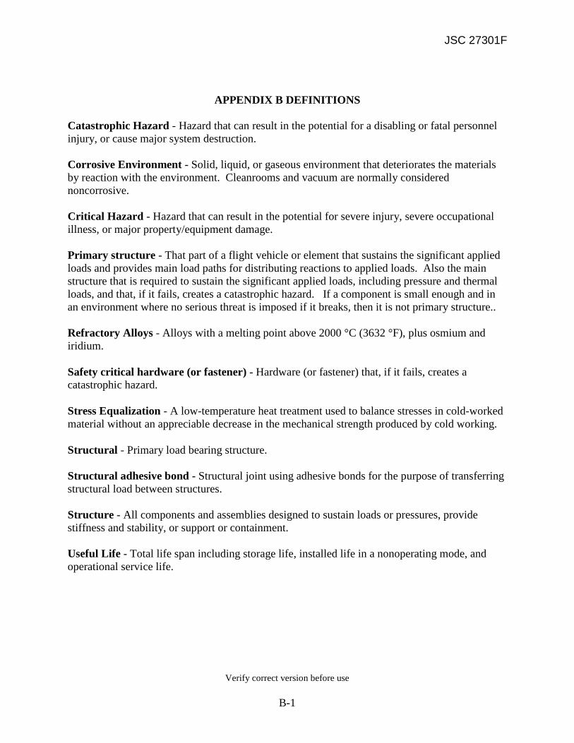
JSC 27301F
Verify correct version before use
B-1
APPENDIX B DEFINITIONS Catastrophic Hazard - Hazard that can result in the potential for a disabling or fatal personnel injury, or cause major system destruction. Corrosive Environment - Solid, liquid, or gaseous environment that deteriorates the materials by reaction with the environment. Cleanrooms and vacuum are normally considered noncorrosive. Critical Hazard - Hazard that can result in the potential for severe injury, severe occupational illness, or major property/equipment damage. Primary structure - That part of a flight vehicle or element that sustains the significant applied loads and provides main load paths for distributing reactions to applied loads. Also the main structure that is required to sustain the significant applied loads, including pressure and thermal loads, and that, if it fails, creates a catastrophic hazard. If a component is small enough and in an environment where no serious threat is imposed if it breaks, then it is not primary structure.. Refractory Alloys - Alloys with a melting point above 2000 °C (3632 °F), plus osmium and iridium.
Safety critical hardware (or fastener) - Hardware (or fastener) that, if it fails, creates a catastrophic hazard.
Stress Equalization - A low-temperature heat treatment used to balance stresses in cold-worked material without an appreciable decrease in the mechanical strength produced by cold working.
Structural - Primary load bearing structure. Structural adhesive bond - Structural joint using adhesive bonds for the purpose of transferring structural load between structures. Structure - All components and assemblies designed to sustain loads or pressures, provide stiffness and stability, or support or containment. Useful Life - Total life span including storage life, installed life in a nonoperating mode, and operational service life.

JSC 27301F
Verify correct version before use
C-1
APPENDIX C
JSC MATERIALS AND FRACTURE CONTROL CERTIFICATION FORM

JSC 27301F
Verify correct version before use
C-2

JSC 27301F
Verify correct version before use
D-1
APPENDIX D
JSC MATERIALS USAGE AGREEMENT FORM
and
JSC VOLATILE USAGE AGREEMENT FORM

JSC 27301F
Verify correct version before use
D-2

JSC 27301F
Verify correct version before use
D-3

JSC 27301F
Verify correct version before use
E-1
APPENDIX E
CATEGORY III MUA RATIONALE CODES
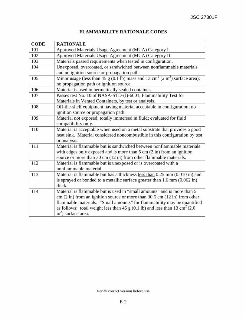
JSC 27301F
Verify correct version before use
E-2
FLAMMABILITY RATIONALE CODES
CODE RATIONALE 101 Approved Materials Usage Agreement (MUA) Category I. 102 Approved Materials Usage Agreement (MUA) Category II. 103 Materials passed requirements when tested in configuration. 104 Unexposed, overcoated, or sandwiched between nonflammable materials
and no ignition source or propagation path. 105 Minor usage (less than 45 g (0.1 lb) mass and 13 cm2 (2 in2) surface area);
no propagation path or ignition source. 106 Material is used in hermetically sealed container. 107 Passes test No. 10 of NASA-STD-(I)-6001, Flammability Test for
Materials in Vented Containers, by test or analysis. 108 Off-the-shelf equipment having material acceptable in configuration; no
ignition source or propagation path. 109 Material not exposed; totally immersed in fluid; evaluated for fluid
compatibility only. 110 Material is acceptable when used on a metal substrate that provides a good
heat sink. Material considered noncombustible in this configuration by test or analysis.
111 Material is flammable but is sandwiched between nonflammable materials with edges only exposed and is more than 5 cm (2 in) from an ignition source or more than 30 cm (12 in) from other flammable materials.
112 Material is flammable but is unexposed or is overcoated with a nonflammable material.
113 Material is flammable but has a thickness less than
114
0.25 mm (0.010 in) and is sprayed or bonded to a metallic surface greater than 1.6 mm (0.062 in) thick. Material is flammable but is used in “small amounts” and is more than 5 cm (2 in) from an ignition source or more than 30.5 cm (12 in) from other flammable materials. “Small amounts” for flammability may be quantified as follows: total weight less than 45 g (0.1 lb) and less than 13 cm2 (2.0 in2) surface area.

JSC 27301F
Verify correct version before use
E-3
TOXICITY (OFFGASSING) RATIONALE CODES
CODE RATIONALE 201 Approved Material Usage Agreement (MUA) Category I. 202 Meets toxicity requirements with performed cure. 203 T value for material/component in usage weight is <0.5 for manned flight
compartment volume. 204 Materials usage in hermetically sealed container.
FLUID SYSTEM COMPATIBILITY RATIONALE CODES
CODE RATIONALE 301 Approved Material Usage Agreement (MUA) Category I. 302 Passes requirements in configuration. 303 Material is B-rated in MAPTIS (batch/lot testing required) but batch/lot
used in hardware passed test. 304 Approved Material Usage Agreement (MUA) Category II.
THERMAL VACUUM STABILITY RATIONALE CODES
CODE RATIONALE 401 Approved Material Usage Agreement (MUA) Category I. 402 Approved Material Usage Agreement (MUA) Category II. 403 VCM between 0.1 and 1.0 percent; exposed area is less than 13 cm2 (2 in2)
and not near a critical surface. 404 VCM >1.0 percent; exposed area is less than 1.6 cm2 (0.25 in2). 405 Unexposed, overcoated, or encapsulated with approved material. 406 Material is B-rated in MAPTIS (batch/lot testing required) but batch/lot
used in hardware cured to meet requirements. 407 Meets thermal vacuum stability requirements in configuration. 408 Materials usage in hermetically sealed container. 409 Material has VCM >0.1 percent but is enclosed in a sealed container
(maximum leak rate less than 1 x 10⁻⁴ cm3/sec).

JSC 27301F
Verify correct version before use
E-4
STRESS CORROSION CRACKING RATIONALE CODES
CODE RATIONALE 501 Approved Material Usage Agreement (MUA) Category I. 502 Approved Material Usage Agreement (MUA) Category II. 503 Maximum tensile stress <50% of yield strength for part on
electrical/electronic assemblies. 504 Martensitic or PH stainless steels used in ball bearing, race, or similar
applications where the primary loading is compressive. 505 Metal not listed in table 1 of MSFC-STD-3029 for stress corrosion
cracking is not exposed to a corrosive environment after final assembly through end-item use.
506 Carbon and low alloy high strength steels greater than 1240 MPa (180 ksi) used in ball bearings, springs, or similar applications where primary loading is compressive, low tensile stresses, or history of satisfactory performance.
CORROSION RATIONALE CODES
CODE RATIONALE 601 Approved Material Usage Agreement (MUA) Category I. 602 Approved Material Usage Agreement (MUA) Category II. 603 Adequately finished for corrosion protection. 604 Acceptable in use environment. 606 Electrical grounding required, cladding plus conversion coating adequate. 607 Thermal conductance and electrical bonding requirements preclude
painting. Conversion coating is adequate (for aluminum only). 608 Finished on a higher assembly. 609 Laminated shim - minimum exposure of corrosion resistant material. 610 Material does not meet the requirements of MSFC-SPEC-250, Class II, but
is treated or coated in a manner which meets or exceeds the requirements of MSFC-SPEC-250. Actual surface treatment shall be listed.
611 Material does not meet the requirements of MSFC-SPEC-250, Class II, but is not exposed to a corrosive environment after final assembly through end-item use.
612 Welding of titanium alloy-to-alloy or commercially pure-to-alloy using commercially pure filler metal in mixed alloy welds where hydrogen embrittlement is not predicted in service.

JSC 27301F
Verify correct version before use
E-5
FLAMMABILITY STOWAGE RATIONALE CODES CODE RATIONALE S01 maximum dimension 10 inches, and unstowed less than 1 day/week
S02 Unstowed less than 1 hour/day
S03 Contingency use only
S04 Maximum dimension less than 6 inches, and always stowed when not in
actual use
S05 Used only when covered by crew clothing S06 Exposed surface area less than 1 square foot, and always worn by crew
when unstowed.
GENERAL CODES
CODE RATIONALE 702 Generic materials controlled by military or industry specification using
MAPTIS averages for ratings or test results. Material codes for generic material shall be used.
703 Military specification or industry specification allowing several material options where all options have acceptable ratings.

JSC 27301F
Verify correct version before use
F-1
APPENDIX F
EXCEPTIONS TO NASA-STD-6016

JSC 27301F
Verify correct version before use
F-2
Exceptions are taken to four requirements in NASA-STD-6016 as follows:

JSC 27301F
Verify correct version before use
F-3
STATEMENT OF REQUIREMENT FROM NASA-STD-6016: 4.1.2 M&P Usage Documentation
d. M&P usage shall be documented in an electronic searchable parts list or separate electronic searchable Materials Identification and Usage List (MIUL).
e. The procedures and formats for documentation of M&P usage depends upon specific hardware but shall cover the final design as delivered.
f. The system used shall be an integral part of the engineering configuration control/release system.
STATEMENT OF IMPLEMENTATION IN JSC 27301F: 4.2 MATERIALS AND PROCESSES USAGE DOCUMENTATION
g. M&P usage shall be documented in an electronic searchable parts list or separate electronic searchable Materials Identification and Usage List (MIUL) for hardware as specified in section 3.2.1 and 3.2.2.
h. The procedures and formats for documentation of M&P usage depends upon specific hardware but shall cover the final design as delivered.
i. The system used shall be an integral part of the engineering configuration control/release system.
d. For human-rated spacecraft, a copy of the stored data shall be provided to NASA in a form compatible with the Materials and Processes Technical Information System (MAPTIS).
MAPTIS is accessible via the Internet at http://maptis.nasa.gov.
Note: Accessibility to MAPTIS is by registration only. Note: For non-plan contractors, the JSC Materials & Processes Branch must be notified by CDR of all Criticality 1 flight hardware for which it is responsible for providing the MIUL and Materials and Fracture Control Certification (as well as any changes "to or from" a Criticality 1 status which might occur after CDR).*** The procedures and formats for documentation of materials and processes usage will depend upon specific hardware but shall cover the final design. EXCEPTION: A Materials Identification and Usage List (MIUL) (or an electronic searchable parts list) will be generated only for Criticality category 1 Space Shuttle and ISS flight hardware. (Criticality

JSC 27301F
Verify correct version before use
F-4
categories are defined in SSP 30234.) Criticality categories 1R, 1S, 1SR and 1P are not included.
A MIUL (or an electronic searchable parts list) will be generated for all Constellation Program flight hardware except noncritical (Criticality 3) flight crew equipment.

JSC 27301F
Verify correct version before use
F-5
STATEMENT OF REQUIREMENT FROM NASA-STD-6016: 4.1.2.3 MIUL Content
a. The parts list, or MIUL, shall identify the following applicable information:
(10) Detail drawing and dash number. (11) Next assembly and dash number. (12) Change letter designation. (13) Drawing source. (14) Material form. (15) Material manufacturer. (16) Material manufacturer's designation. (17) Material specification. (18) Process specification. (10) Environment. (11) Weight (nonmetallic materials). (12) MAPTIS material code (if data are to be provided in a form compatible with
MAPTIS). (13) Standard/commercial part number. (14) Contractor. (15) System. (16) Subsystem. (17) Maximum operating temperature. (18) Minimum operating temperature. (19) Fluid type. (20) Surface area (nonmetallic materials). (21) Associate contractor number. (22) Project. (23) Document title. (24) Criticality. (25) Line number. (26) Overall evaluation. (27) Overall configuration test. (28) Maximum operating pressure. (29) Minimum operating pressure. (30) MUA number or rationale code. (31) Cure codes. (32) Materials rating. (33) Remarks (comments field).
b. MAPTIS shall be consulted to obtain material codes and ratings for materials,
standard and commercial parts, and components. c. New material codes shall be assigned by NASA’s Marshall Space Flight Center
(MSFC).
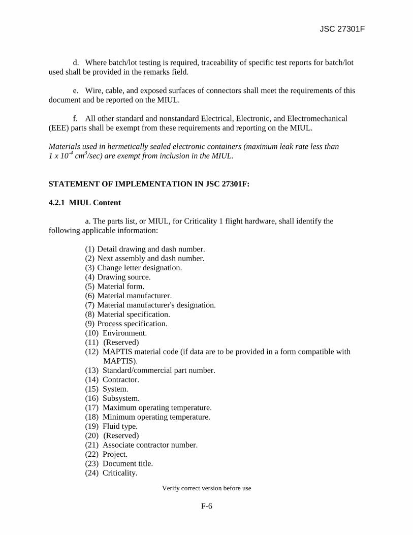
JSC 27301F
Verify correct version before use
F-6
d. Where batch/lot testing is required, traceability of specific test reports for batch/lot
used shall be provided in the remarks field. e. Wire, cable, and exposed surfaces of connectors shall meet the requirements of this
document and be reported on the MIUL. f. All other standard and nonstandard Electrical, Electronic, and Electromechanical
(EEE) parts shall be exempt from these requirements and reporting on the MIUL.
Materials used in hermetically sealed electronic containers (maximum leak rate less than 1 x 10⁻⁴ cm3/sec) are exempt from inclusion in the MIUL. STATEMENT OF IMPLEMENTATION IN JSC 27301F: 4.2.1 MIUL Content a. The parts list, or MIUL, for Criticality 1 flight hardware, shall identify the following applicable information:
(1) Detail drawing and dash number. (2) Next assembly and dash number. (3) Change letter designation. (4) Drawing source. (5) Material form. (6) Material manufacturer. (7) Material manufacturer's designation. (8) Material specification. (9) Process specification. (10) Environment. (11) (Reserved) (12) MAPTIS material code (if data are to be provided in a form compatible with
MAPTIS). (13) Standard/commercial part number. (14) Contractor. (15) System. (16) Subsystem. (17) Maximum operating temperature. (18) Minimum operating temperature. (19) Fluid type. (20) (Reserved) (21) Associate contractor number. (22) Project. (23) Document title. (24) Criticality.

JSC 27301F
Verify correct version before use
F-7
(25) Line number. (26) Overall evaluation. (27) Overall configuration test. (28) Maximum operating pressure. (29) Minimum operating pressure. (30) MUA number or rationale code. (31) Cure codes. (32) Materials rating. (33) Remarks (comments field).
b. MAPTIS shall be consulted to obtain material codes and ratings for materials,
standard and commercial parts, and components. c. New material codes shall be assigned by NASA’s Marshall Space Flight Center
(MSFC).
d. Where batch/lot testing is required, traceability of specific test reports for batch/lot used shall be provided in the remarks field.
e. Wire, cable, and exposed surfaces of connectors shall meet the requirements of
this document and be reported on the MIUL. f. All other standard and nonstandard Electrical, Electronic, and Electromechanical
(EEE) parts shall be exempt from these requirements and reporting on the MIUL.
Materials used in hermetically sealed electronic containers (maximum leak rate less than 1 x 10⁻⁴ cm3/sec) are exempt from inclusion in the MIUL. Ground Support Equipment which is not used within 3 feet of flight hardware or does not have any operational, physical, or fluid system interfaces is exempt from inclusion in the MIUL. EXCEPTION: Nonmetallic materials weight and surface area will not be reported in the MIUL.

JSC 27301F
Verify correct version before use
F-8
STATEMENT OF REQUIREMENT FROM NASA-STD-6016:
4.1.5 Materials Certification and Traceability
a. All parts or materials shall be certified as to composition, properties, and requirements as identified by the procuring document.
b. Parts and materials used in critical applications, such as life-limited materials and/or safety- and fracture-critical parts, shall be traceable through all processing steps defined in the engineering drawing to the end-item application.
c. Processing records shall be retained for the life of the program. STATEMENT OF IMPLEMENTATION IN JSC 27301F: 4.6 MATERIALS CERTIFICATION AND TRACEABILITY
a. All parts or materials used in manufacturing JSC flight hardware shall be certified as to composition and properties as identified by the procuring document.
Noncritical commercial off-the-shelf hardware is exempted from this requirement.
b. Parts and materials used in critical applications such as life-limited materials, safety and fracture critical parts shall be traceable through all all processing steps defined in the engineering drawing to the end-item application.
c. Processing records shall be retained for the life of the program.
EXCEPTION: Requirement that parts or materials be certified as to composition and properties is waived for noncritical (criticality 3) off-the-shelf hardware.

JSC 27301F
Verify correct version before use
F-9
STATEMENT OF REQUIREMENT FROM JSC NASA-STD-6016: 4.2.2.2.1 Heat Treatment of Steels
a. Steel parts shall be heat-treated to meet the requirements of SAE-AMS-H-6875, Heat Treatment of Steel Raw Materials, or SAE-AMS 2759, Heat Treatment of Steel Parts, General Requirements.
b. When high-strength steels (>200 ksi (1380 MPa) UTS), tool steels, and maraging steel alloys are heat-treated to high strength levels, process-control tensile-test coupons shall be taken from the production part (or from the same material lot and processed identically to the production part) to verify the adequacy of the heat treatment process. (1) The requirement for process control coupons shall be specified on the engineering
drawing for the part. (2) For all other steels (including alloy steels), the adequacy of the heat treatment
process shall be verified by hardness measurements. (3) Hardenability limits of low alloy steels shall be taken into consideration when
design is constrained by part size and uniformity of material mechanical properties.
c. When acid cleaning baths or plating processes are used, the part shall be baked in
accordance with SAE-AMS 2759/9, Hydrogen Embrittlement Relief (Baking) of Steel Parts, to alleviate potential hydrogen embrittlement problems. STATEMENT OF IMPLEMENTATION IN JSC 27301F: 5.2.2.1 Heat Treatment of Steels a. Steel parts shall be heat treated to meet the requirements of SAE-AMS-H-6875, Heat Treatment of Steel Raw Materials, or SAE-AMS 2759, Heat Treatment of Steel Parts, General Requirements. b. When high-strength steels (>200 ksi) with the exception of Custom 455 and Custom 465 alloys, tool steels, and maraging steel alloys are heat treated to high strength levels, process-control tensile-test coupons shall be taken from the production part (or from the same material lot and processed identically to the production part) to verify the adequacy of the heat treatment process.
(1) The requirement for process control coupons shall be specified on the engineering drawing for the part.

JSC 27301F
Verify correct version before use
F-10
(2) For all other steels (including alloy steels), the adequacy of the heat treatment process shall be verified by hardness measurements.
(3) Hardenability limits of low alloy steels shall be taken into consideration when design
is constrained by part size and uniformity of material mechanical properties. (4) Age hardening of Custom 455 and Custom 465 alloys shall also be verified by
hardness measurements.
c. When acid cleaning baths or plating processes are used, the part shall be baked in accordance with SAE-AMS 2759/9, Hydrogen Embrittlement Relief (Baking) of Steel Parts, to alleviate potential hydrogen embrittlement problems. EXCEPTION: Tensile-test coupons are not required to verify the adequacy of the heat treatment process for age-hardened Custom 455 and Custom 465 alloys. Hardness tests are considered to be adequate and are used instead.