Embed Size (px)
Citation preview
→ Materials science laboratory (Msl)
The Materials Science Laboratory supports microgravity research in the areas of solidification physics, measurement of thermo-physical properties of materials and semiconductor crystal growth (Bridgman and zone melting), using exchangeable Furnace Inserts (FI)
Material physics research facility in Destiny
ERASMUS Centre - Directorate of Human Spaceflight and Operations
PROJECT:
TITLE: MSL DOCUMENT N°:
International Space Station
ESA-HSO-COU-015 2.0REV.
Power Supply Unit (PSU)
Gas Supply (GS) Drawer
Vacuum Gas Subsystem (VGS)/Water Pump
Package (WPP)
Facility Control Unit (FCU)
Core Facility (CF)
Foot restraint
1046
432
1580
1836 20
14
?????
?????
Materials Science Laboratory furnace insert characteristics Solidification and Low Gradient Quenching Furnace Furnace TECHNICAL DATA Max. temperature hot cavity heater diffuser: 1,673 K 1,673 K Max. temperature cold cavity heater diffuser: n.a. 1,477 K Axial temperature uniformity of main heaters: <= 0.7 K <= 0.5 K Temperature stability (degrees K): +/- 0.1 (T > 773) +/- 0.02 (T > 1073) Circumferential thermal uniformity (degrees K): +/- 0.25 +/- 0.5 Maximum thermal gradient (degrees K/cm): >= 150 >= 50 Diameter of furnace bore (mm): 30 30 Length of hot cavity zone (mm): 250 200 Length of adiabatic zone (mm): 50 – 100 (variable) 50 Diameter of adiabatic zone (mm): 11 - 30 30 Length of cold cavity zone (mm): n.a. 120 Length of cooling zone (mm): 50 n.a. Processing stroke: 150 mm 150 mm Processing speed (mm/s): 10-5 - 2 - Rotating magnetic field: Yes Yes Magnetic flux density: 0 - 3.5 mT 0 - 3.5 mT (orthogonal to and rotating around the furnace axis) Magnetic field frequencies (1 Hz steps): 0 and 5 - 400 Hz Thermocouples: Up to 12 individually selectable Peltier Pulse marking: Yes Sample resistance measurement: Yes Seebeck voltage measurement: Yes Cartridge shear cell activation: Yes Fast quenching speeds: to 100 mm/s selectable or 100 mm dis- placement within 1s Differential thermal analysis: By thermocouple zoom Ultrasound Diagnostics: Yes 3-Axis Accelerometer Measurement range: 10-6 - 10-3 g Frequency range: 0.1 - 30 Hz Processing Drive Velocity range: 10-5 - 0.2 mm/s Speed stability: +/- 1.5 % Max. displacement step: 0.8 μm Quench Drive Velocity range: 1 - 100 mm/s Furnace displacement including acceleration and deceleration: 100 mm in 1 s
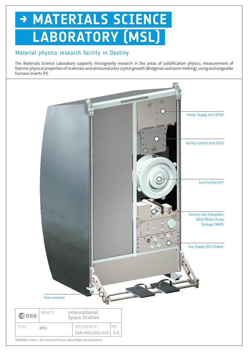
The Materials Science Laboratory (MSL) facility is the ESA contribution to NASA's First Materials Science Research Rack (MSRR-1) in the US Laboratory Module Destiny of the International Space Station. It occupies one half of a standard payload rack.
The MSL consists of a Core Facility, together with associ-ated support sub-systems. The Core Facility consists mainly of a vacuum-tight stainless steel cylinder (Process Chamber) capable of accommodating different individual Furnace Inserts (FI), within which sample processing is carried out. The process chamber provides an accurately controlled processing environment and measurement of microgravity levels. It houses different exchangeable FIs and a high-precision FI drive mechanism. Processing conditions are normally either a vacuum or an inert gas (e.g. Argon). The process chamber is divided by an Intermediate Support Plate that acts as a mechanical interface for the experiment cartridge - Sample Cartridge Assembly (SCA).
The Core Facility supports FIs with up to eight heating elements, and provides the mechanical, thermal and electrical infrastructure necessary to handle the FIs, the experiment cartridge (SCA), together with any associated experiment-dedicated electronics that may be required. The microgravity levels during an experimental run are measured by an integrated three-axis accelerometer package. Access to exchange a FI is achieved by opening
the process chamber lid, and removing the Intermediate Support Plate.
A FI is an arrangement of heating elements, isolating zones and cooling zones contained in a thermal insula-tion assembly. On the outer envelope of this assembly is a water-cooled metal jacket forming the mechanical interface to the Core Facility.
The major characteristics of the 2 proposed Furnace Inserts are:
• Low Gradient Furnace (LGF)The LGF is designed mainly for Bridgman crystal growth of semiconductor materials. It consists of two heated cavities separated by an adiabatic zone. This assembly can establish low and precisely controlled gradients between two very stable temperature pla-teaux.
• Solidification and Quenching Furnace (SQF)The SQF is designed mainly for metallurgical research, with the option of quenching the solidification interface at the end of processing by quickly displacing the cooling zone. It consists of a heated cavity and a water-cooled cooling zone separated by an adiabatic zone. It can establish medium to steep temperature gradients along the experiment sample. For creating large gradients, a Liquid Metal Ring enhances the
Specifications
thermal coupling between the SCA and the cooling zone.
Sample Cartridge Assembly (SCA)Technical Data
The samples to be processed are contained in experiment cartridges, the SCA, that consist of a leak-tight tube, crucible, sensors for process control, sample probe and cartridge foot (i.e. the mechanical and electrical interface to the process chamber). The MSL safety concept requires that experiment samples containing toxic compounds are contained in SCAs that support the detection of potential leaks. The volume between the experiment sample and the cartridge tube is filled with a pre-defined quantity of krypton, allowing leak detection by mass spectrometry.
• Up to 12 scientific thermocouples providing the sample's temperature profile and allowing differential thermal analy sis;
• Peltier pulse interface indexing: 2 pulse sources 0 - 50 A and 0 - 40 V each, maximum power 30 W each; series and parallel operation possible, combined maximum power 600 W; pulse duration range 100 ms - 4 s, pulse grouping possible, min. time between pulse groups 14s;
• Shear cell activation for thermo-diffusion experiments;• Reservoir heating for maintaining a controlled vapour pressure for volatile experiment materials;
• Experiment-dedicated diagnostics: Seebeck Voltage and Sample Resistance measurement for real-time in situ monitoring of composition and temperature at the growth interface as well as position and speed of the solid/liquid front; Ultrasound diagnostics for real-time in-situ detection of location and velocity of the solid/liquid interface; other diagnostics, yet to be defined.
Facility Description
966
750
The Materials Science Laboratory (MSL) facility is the ESA contribution to NASA’s First Materials Science Research Rack (MSRR-1) in the US Laboratory Module Destiny of the International Space Station. It occupies one half of a standard payload rack.
The MSL consists of a Core Facility, together with associated support sub-systems. The Core Facility consists mainly of a vacuum-tight stainless steel cylinder (Process Chamber) capable of accommodating different individual Furnace Inserts (FI), within which sample processing is carried out. The process chamber provides an accurately controlled processing environment and measurement of microgravity levels. It houses different exchangeable FIs and a high-precision FI drive mechanism. Processing conditions are normally either a vacuum or an inert gas (e.g. Argon). The process chamber is divided by an Intermediate Support Plate that acts as a mechanical interface for the experiment cartridge - Sample Cartridge Assembly (SCA).
The Core Facility supports FIs with up to eight heating elements, and provides the mechanical, thermal and electrical infrastructure necessary to handle the FIs, the experiment cartridge (SCA), together with any associated experiment-dedicated electronics that may be required. The microgravity levels during an experimental run are measured by an integrated three-axis accelerometer package. Access to exchange a FI is achieved by opening the process chamber lid, and removing the Intermediate Support Plate.
Facility Description
A FI is an arrangement of heating elements, isolating zones and cooling zones contained in a thermal insulation assembly. On the outer envelope of this assembly is a water-cooled metal jacket forming the mechanical interface to the Core Facility.
The major characteristics of the 2 proposed Furnace Inserts are:
Low Gradient Furnace (LGF)• The LGF is designed mainly for Bridgman crystal growth of semiconductor materials. It consists of two heated cavities separated by an adiabatic zone. This assembly can establish low and precisely controlled gradients between two very stable temperature plateaux.
Solidification and Quenching Furnace (SQF)•The SQF is designed mainly for metallurgical research, with the option of quenching the solidification interface at the end of processing by quickly displacing the cooling zone. It consists of a heated cavity and a water-cooled cooling zone separated by an adiabatic zone. It can establish medium to steep temperature gradients along the experiment sample. For creating large gradients, a Liquid Metal Ring enhances the thermal coupling between the SCA and the cooling zone.
SAMpLE CArtrIdGE ASSEMbLy (SCA) tECHnICAL dAtAThe samples to be processed are contained in experiment cartridges, the SCA, that consist of a leak-tight tube, crucible, sensors for process control, sample probe and
Solidification and Low Gradient Quenching Furnace Furnace
tECHnICAL dAtAMax. temperature hot cavity heater diffuser: 1,673 K 1,673 KMax. temperature cold cavity heater diffuser: n.a. 1,477 KAxial temperature uniformity of main heaters: <= 0.5 K <= 0.5 KTemperature stability (degrees K): +/- 0.1 (T > 773) +/- 0.02 (T > 1073) Circumferential thermal uniformity (degrees K): +/- 0.25 +/- 0.5Maximum thermal gradient (degrees K/cm): 150 up to 40Diameter of furnace bore (mm): 30 30Length of hot cavity zone (mm): 250 200Length of adiabatic zone (mm): 50 – 100 (variable) 50Diameter of adiabatic zone (mm): 11 - 30 30Length of cold cavity zone (mm): n.a. 120Length of cooling zone (mm): 50 n.a. Processing stroke: 150 mm 150 mmProcessing speed (mm/s): 10-5 - 2 10-5 - 2Rotating magnetic field: Yes YesMagnetic flux density: 0 - 3.5 mT 0 - 3.5 mT(orthogonal to and rotating around the furnace axis)Magnetic field frequencies (1 Hz steps): 0 and 5 - 400 HzThermocouples: Up to 12 individually selectablePeltier Pulse marking: YesSample resistance measurement: YesSeebeck voltage measurement: YesCartridge shear cell activation: YesDifferential thermal analysis: By thermocouple zoomUltrasound Diagnostics: Yes3-Axis AccelerometerMeasurement range: 10-6 - 10-3 gFrequency range: 0.1 - 30 Hzprocessing driveVelocity range: 10-5 - 0.2 mm/sSpeed stability: +/- 1.5 %Max. displacement step: 0.8 µmQuench driveVelocity range: 6 - 100 mm/sFurnace displacement including acceleration and deceleration: 100 mm in 1 s
SpecificationsMaterials Science Laboratory furnace insert characteristics
grouping possible, min. time between pulse groups 14s;Shear cell activation for thermo-diffusion •experiments;Reservoir heating for maintaining a controlled vapour •pressure for volatile experiment materials;Experiment-dedicated diagnostics: Seebeck Voltage •and Sample Resistance measurement for real-time in situ monitoring of composition and temperature at the growth interface as well as position and speed of the solid/liquid front; Ultrasound diagnostics for real-time in-situ detection of location and velocity of the solid/liquid interface.
cartridge foot (i.e. the mechanical and electrical interface to the process chamber). The MSL safety concept requires that experiment samples containing toxic compounds are contained in SCAs that support the detection of potential leaks. The volume between the experiment sample and the cartridge tube is filled with a pre-defined quantity of krypton, allowing leak detection by mass spectrometry.
Up to 12 scientific thermocouples providing the •sample’s temperature profile and allowing differential thermal analysis;Peltier pulse interface indexing: 2 pulse sources 0 - 50 •A and 0 - 40 V each, maximum power 30 W each; series and parallel operation possible, combined maximum power 600 W; pulse duration range 100 ms - 4 s, pulse
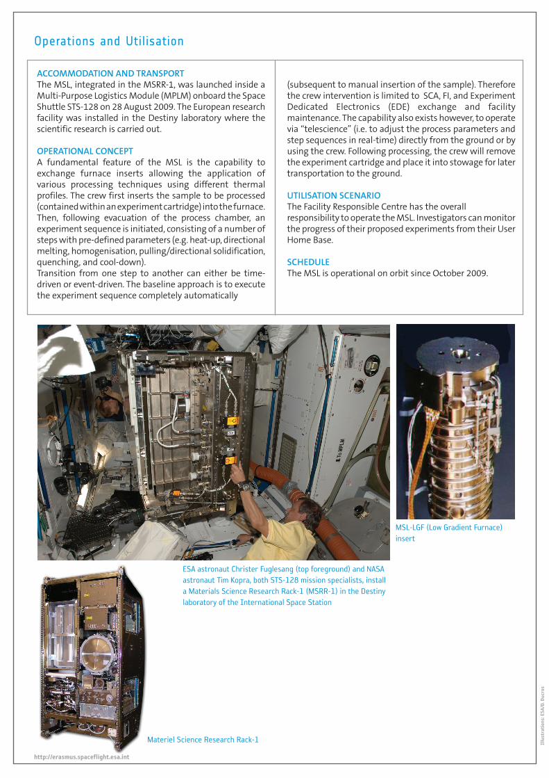
ACCOMMOdAtIOn And trAnSpOrtThe MSL, integrated in the MSRR-1, was launched inside a Multi-Purpose Logistics Module (MPLM) onboard the Space Shuttle STS-128 on 28 August 2009. The European research facility was installed in the Destiny laboratory where the scientific research is carried out.
OpErAtIOnAL COnCEptA fundamental feature of the MSL is the capability to exchange furnace inserts allowing the application of various processing techniques using different thermal profiles. The crew first inserts the sample to be processed (contained within an experiment cartridge) into the furnace. Then, following evacuation of the process chamber, an experiment sequence is initiated, consisting of a number of steps with pre-defined parameters (e.g. heat-up, directional melting, homogenisation, pulling/directional solidification, quenching, and cool-down). Transition from one step to another can either be time-driven or event-driven. The baseline approach is to execute the experiment sequence completely automatically
Operations and Utilisation
http://erasmus.spaceflight.esa.int
Illu
stra
tion
s: E
SA/D
. Duc
ros
(subsequent to manual insertion of the sample). Therefore the crew intervention is limited to SCA, FI, and Experiment Dedicated Electronics (EDE) exchange and facility maintenance. The capability also exists however, to operate via “telescience” (i.e. to adjust the process parameters and step sequences in real-time) directly from the ground or by using the crew. Following processing, the crew will remove the experiment cartridge and place it into stowage for later transportation to the ground.
UtILISAtIOn SCEnArIOThe Facility Responsible Centre has the overall responsibility to operate the MSL. Investigators can monitor the progress of their proposed experiments from their User Home Base.
SCHEdULEThe MSL is operational on orbit since October 2009.
ESA astronaut Christer Fuglesang (top foreground) and NASA astronaut Tim Kopra, both STS-128 mission specialists, install a Materials Science Research Rack-1 (MSRR-1) in the Destiny laboratory of the International Space Station
MSL-LGF (Low Gradient Furnace) insert
Materiel Science Research Rack-1