Embed Size (px)
Citation preview
Maximum Power Point Tracking Charge Controller
User’s GuideInstallation, Programming and User’s Manual
maxTM 80
�PB
Warranty Summary Dear OutBack Customer,Thank you for your purchase of OutBack products. We make every effort to assure our powerconversion products will give you long and reliable service for your renewable energy system.
As with any manufactured device, repairs might be needed due to damage, inappropriate use, or unintentional defect. Please note the following guidelines regarding warranty service of OutBack products:• Any and all warranty repairs must conform to the terms of the warranty.• All OutBack equipment must be installed according to their accompanying instructions and
manuals with specified over-current protection in order to maintain their warranties.• The customer must return the component(s) to OutBack, securely packaged, properly addressed,
and shipping paid. We recommend insuring your package when shipping. Packages that are not securely packaged can sustain additional damage not covered by the warranty or can void warranty repairs.
• There is no allowance or reimbursement for an installer’s or user’s labor or travel time required to disconnect, service, or reinstall the damaged component(s).
• OutBack will ship the repaired or replacement component(s) prepaid to addresses in the continental United States, where applicable. Shipments outside the U.S. will be sent freight collect.
• In the event of a product malfunction, OutBack cannot bear any responsibility for consequential losses, expenses, or damage to other components.
• Please read the full warranty at the end of this manual for more information.
�PB
The OutBack Power Systems FLEXmax 80 Maximum Power Point Tracking Charge Controller is ETL listed in North America to UL1741 (Inverters, Converters, Controllers, and Interconnection System Equipment for Use with Distributed Energy Resources). It is also in compliance with European Union standards EN 61000-6-1 and EN 61000-6-3 (see page 89).
About OutBack Power SystemsOutBack Power Systems is a leader in advanced energy conversion technology. Our products include true sine wave inverter/chargers, a maximum power point charge controller, system communication components, as well as breaker panels, breakers, accessories, and assembled systems.
Notice of Copyright
FLEXmax 80 Maximum Power Point Tracking Charge Controller User’s Guide: Installation, Programming and User’s Manual Copyright © 2008 All rights reserved.
DisclaimerUNLESS SPECIFICALLY AGREED TO IN WRITING, OUTBACK POWER SYSTEMS:(a) MAKES NO WARRANTY AS TO THE ACCURACY, SUFFICIENCY OR SUITABILITY OF ANY TECHNICAL OR OTHER INFORMATION PROVIDED IN ITS MANUALS OR OTHER DOCUMENTATION.(b) ASSUMES NO RESPONSIBILITY OR LIABILITY FOR LOSS OR DAMAGE, WHETHER DIRECT,INDIRECT, CONSEQUENTIAL OR INCIDENTAL, WHICH MIGHT ARISE OUT OF THE USE OF SUCHINFORMATION. THE USE OF ANY SUCH INFORMATION WILL BE ENTIRELY AT THE USER’S RISK.
Date and RevisionJanuary 2008 REV A
Contact InformationOutBack Power Systems19009 62nd Ave. NEArlington, WA 98223Phone (360) 435-6030 Fax (360) 435-6019www.outbackpower.com
�PB
TABLE OF CONTENTS
SCOPE ....................................................................................................................................................................................................... 5INTRODUCTION .................................................................................................................................................................................. 5INSTALLATION GUIDELINES AND SAFETY INSTRUCTIONS ....................................................................................... 6 Standards and Requirements ........................................................................................................................................... 6 Battery Safety .............................................................................................................................................................................. 7INSTALLING THE FLEXmax 80 ON FLEXware ENCLOSURES ..................................................................................... 9OPEN CIRCUIT VOLTAGE/WIRE AND DISCONNECT SIZING ................................................................................... 10HOW TO READ THE FLEXmax 80 SCREEN DIAGRAMS ............................................................................................. 15POWERING UP .................................................................................................................................................................................. 16STATUS SCREEN ................................................................................................................................................................................ 19END OF DAY SUMMARY SCREEN .......................................................................................................................................... 19RECHARGING USING THE PV ARRAY ................................................................................................................................... 19ACCESSING THE MAIN MENU .................................................................................................................................................. 21CHARGER SETUP ............................................................................................................................................................................. 22AUX MODE AND ITS FUNCTIONS ......................................................................................................................................... 23 AUX Mode Path ...................................................................................................................................................................... 24 AUX Modes Described ....................................................................................................................................................... 25 Programming the AUX Modes ..................................................................................................................................... 26 Vent Fan ............................................................................................................................................................................ 26 PV Trigger ......................................................................................................................................................................... 27 Error Output ................................................................................................................................................................... 30 Night Light ...................................................................................................................................................................... 31 Float ..................................................................................................................................................................................... 33 Diversion: Relay ............................................................................................................................................................ 33 Diversion: Solid State ................................................................................................................................................ 35 Low Battery Disconnect .......................................................................................................................................... 37 Remote .............................................................................................................................................................................. 39BACKLIGHT.......................................................................................................................................................................................... 40EQ (Equalize) ...................................................................................................................................................................................... 40MISC-MISCELLANEOUS ............................................................................................................................................................... 43ADVANCED ......................................................................................................................................................................................... 45 Snooze Mode........................................................................................................................................................................... 45 Wakeup Mode ......................................................................................................................................................................... 46 MPPT Mode .............................................................................................................................................................................. 46 Park Mpp .................................................................................................................................................................................... 47CHARGING RELATED SCREENS ............................................................................................................................................... 48 Absorb Time ............................................................................................................................................................................. 48 Rebulk Voltage ........................................................................................................................................................................ 49
�PB
Vbatt Calibration ..........................................................................................................................................................................50 RTS Compensation .....................................................................................................................................................................50 Auto Restart ....................................................................................................................................................................................51 Aux Polarity .....................................................................................................................................................................................52 Reset to Defaults? .......................................................................................................................................................................52(DATA) LOGGING ....................................................................................................................................................................................54 Clearing Total and Daily Stats ...............................................................................................................................................54STATS .............................................................................................................................................................................................................55 Secondary Stats Screen ............................................................................................................................................................56MICRO-HYDRO, WIND TURBINE, AND FUEL CELL APPLICATIONS............................................................................57ADVANCED MENU (Micro-Hydro) ...............................................................................................................................................58FLEXmax 80 ABBREVIATED MENU MAP ...................................................................................................................................59APPLICATION NOTES ...........................................................................................................................................................................60FLEXmax 80 EFFICIENCY vs. INPUT POWER GRAPH .........................................................................................................61UNDERSTANDING THE VARIOUS OPERATIONAL MODES ..............................................................................................62MATE-DISPLAYED CHARGE CONTROLLER STATUS MODE Screens .........................................................................65MATE-DISPLAYED CHARGE CONTROLLER STATUS METER Screens .......................................................................66MATE-DISPLAYED CHARGE CONTROLLER STATUS SETP(OINT) Screens ..............................................................67MATE-DISPLAYED FLEXmax 80 ADVANCED SCREENS ....................................................................................................67ADVANCED MENU ................................................................................................................................................................................68EQ SCREENS ..............................................................................................................................................................................................69AUX SCREENS ...........................................................................................................................................................................................69ABBREVIATED MENU ............................................................................................................................................................................70TROUBLESHOOTING GUIDE ............................................................................................................................................................72TYPICAL ARRAY SIZING GUIDE ......................................................................................................................................................75STANDARD vs. AUSTRALIAN DEFAULT SETTINGS ...............................................................................................................76WIRE DISTANCE CHART ......................................................................................................................................................................77WIRE AND DISCONNECT SIZING ..................................................................................................................................................79MULTI-STAGE BATTERY CHARGING .............................................................................................................................................81BATTERY TEMPERATURE COMPENSATED VOLTAGE SET POINT .................................................................................83SUGGESTED BATTERY CHARGER SET POINTS ......................................................................................................................84CALLING THE FACTORY FOR ASSISTANCE ..............................................................................................................................85WARRANTY INFORMATION ..............................................................................................................................................................86PRODUCT REGISTRATION AND OPTIONAL EXTENDED WARRANTY ......................................................................88EU DECLARATION OF CONFORMITY..........................................................................................................................................89OWNER’S SYSTEM INFORMATION ............................................................................................................................................. 90
�PB
SCOPEThe manual provides safety guidelines and installation information for the FLEXmax 80 Maximum Power Point Tracking Charge Controller. It does not provide information about specific brands of solar panels and supplies limited information on batteries. Contact the supplier or manufacturer of the solar panels or batteries for further information.
INTRODUCTIONFLEXmax 80 Maximum Power Point Tracking Charge Controller
The OutBack FLEXmax 80 Maximum Power Point Tracking Charge Controller offers an efficient, safe, multi-
stage recharging process that prolongs battery life and assures peak performance from a solar array. This component allows customized battery recharging. The FLEXmax 80 features include:• 80 amps maximum continuous output current up to 40° C without thermal derating• Engineered to work with 12, 24, 36, 48, and 60VDC battery voltages• Backlit LCD display screen with 80 characters (4 lines, 20 characters per line)• Last 128 days of operational data are logged for review• Voltage step-down capability allowing a higher PV array voltage configuration• Manual and auto-equalize cycle
The following are the maximum recommended wattage for the most common solar arrays underStandard Test Conditions (1000 watts per square meter to solar panel at 25° C or 77° F):• 12VDC battery systems—up to 1250 watts of solar panels• 24VDC battery systems—up to 2500 watts of solar panels• 36VDC battery systems—up to 3750 watts of solar panels• 48VDC battery systems—up to 5000 watts of solar panels• 60VDC battery systems—up to 6250 watts of solar panels
The FLEXmax 80 also features Continuous Maximum Power Point Tracking (MPPT), which seeks out the maximum power available from a solar array and uses it to recharge the batteries. Without this feature, the solar array does not operate at the ideal operating voltage and can only recharge at the level of the battery voltage itself. The FLEXmax 80 continuously tracks the array’s maximum operating power.
This manual covers the wiring, installation, and use of the FLEXmax 80, including explanations of all the menus displayed on the LCD screen. The FLEXmax 80 is designed to seamlessly integrate with other OutBack components and can be remotely monitored and configured (up to 1000 feet) by the optional OutBack Power Systems MATE display (version 4.0.4 or greater).
FIRMWAREThis manual covers FLEXmax 80 firmware version 001.008.009
�PB
OUTBACK FLEXmax 80 CHARGE CONTROLLER INSTALLATION GUIDELINES AND SAFETY INSTRUCTIONS
This product is intended to be installed as part of a permanently grounded electrical system as shown in the system configuration sections (see pages 12-14) of this manual. The following important restrictions apply unless superseded by local or national codes:• The negative battery conductor should be bonded to the grounding system at only one point in the
system. If a GFP is present, the battery negative and ground are not bonded together directly but are connected together by the GFP device when it is on. All negative conductor connections must be kept separate from the grounding conductor connections.
• With the exception of certain telcom applications, the FLEXmax 80 should never be positive grounded (see page 60, Applications Notes).
• The FLEXmax 80 equipment ground is marked with this symbol:• If damaged or malfunctioning, the FLEXmax 80 should only be disassembled and repaired by a
qualified service center. Please contact your renewable energy dealer/installer for assistance. Incorrect reassembly risks malfunction, electric shock or fire.
• The FLEXmax 80 is designed for indoor installation or installation inside a weatherproof enclosure. It must not be exposed to rain and should be installed out of direct sunlight.
For routine, user-approved maintenance:• Turn off all circuit breakers, including those to the solar modules, and related electrical connections
before cleaning the air vents.
Standards and RequirementsAll installations must comply with national and local electrical codes; professional installation is recommended. NEC requires ground protection for all residential PV installations
DC and Battery-Related Installation Requirements:
• All DC cables must meet NEC standards.• Shut off all DC breakers before connecting any wiring.• Torque all the FLEXmax 80’s wire lugs and ground terminals to 35 inch-pounds (4 Nm).• All wiring must be rated at 75° C or higher.• Use up to 2 AWG (33.6 mm2 ) to reduce losses and ensure high performance of FLEXmax 80 (smaller
cables can reduce performance and possibly damage the unit).• Keep cables together (e.g., using a tie-wrap) as much as possible.• Ensure both cables pass through the same knockout and conduit fittings to allow the inductive
currents to cancel.• DC battery over-current protection must be used as part of the installation. OutBack offers both

�PB
WARNING - WORKING IN THE VICINITY OF A LEAD ACID BATTERY IS DANGEROUS. BATTERIES GENERATE EXPLOSIVE GASES DURING NORMAL OPERATION. Design the battery enclosure to prevent accumulation and concentration of hydrogen gas in “pockets” at the top of the enclosure. Vent the battery compartment from the highest point to the outside. A sloped lid can also be used to direct the flow of hydrogen to the vent opening. CAUTION - To reduce risk of injury, charge only deep-cycle lead acid, lead antimony, lead calcium, gel cell or absorbed glass mat type rechargeable batteries. Other types of batteries may burst, causing personal injury and damage. Never charge a frozen battery.
PERSONAL PRECAUTIONS DURING INSTALLATION• Someone should be within range of your voice to come to your aid if needed.• Keep plenty of fresh water and soap nearby in case battery acid contacts skin, clothing,
or eyes.• Wear complete eye protection. Avoid touching eyes while working near batteries. Wash your hands
with soap and warm water when done.• If battery acid contacts skin or clothing, wash immediately with soap and water. If acid enters an eye,
flood the eye with running cool water at once for at least 15 minutes and get medical attention immediately following.• Baking soda neutralizes lead acid battery electrolyte. Keep a supply on hand in the area of
the batteries.• NEVER smoke or allow a spark or flame in vicinity of a battery or generator.• Be extra cautious to reduce the risk of dropping a metal tool onto batteries. It could short-circuit the
batteries or other electrical parts that can result in fire or explosion.• Remove personal metal items such as rings, bracelets, necklaces, and watches when working with a
battery or other electrical current. A battery can produce a short circuit current high enough to weld a ring or the like to metal, causing severe burns.
8PB
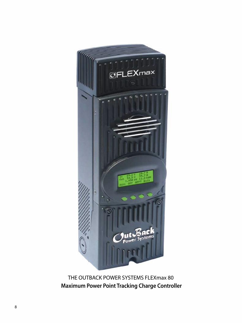
THE OUTBACK POWER SYSTEMS FLEXmax 80 Maximum Power Point Tracking Charge Controller
�PB
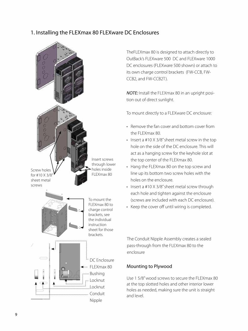
TheFLEXmax 80 is designed to attach directly to OutBack’s FLEXware 500 DC and FLEXware 1000 DC enclosures (FLEXware 500 shown) or attach to its own charge control brackets (FW-CCB, FW-CCB2, and FW-CCB2T).
NOTE: Install the FLEXmax 80 in an upright posi-tion out of direct sunlight.
To mount directly to a FLEXware DC enclosure:
• Remove the fan cover and bottom cover from the FLEXmax 80.
• Insert a #10 X 3/8” sheet metal screw in the top hole on the side of the DC enclosure. This will act as a hanging screw for the keyhole slot at the top center of the FLEXmax 80.
• Hang the FLEXmax 80 on the top screw and line up its bottom two screw holes with the holes on the enclosure.
• Insert a #10 X 3/8” sheet metal screw through each hole and tighten against the enclosure (screws are included with each DC enclosure).
• Keep the cover off until wiring is completed.
The Conduit Nipple Assembly creates a sealed pass-through from the FLEXmax 80 to the enclosure
�. Installing the FLEXmax 80 FLEXware DC Enclosures
Mounting to Plywood
Use 1 5/8” wood screws to secure the FLEXmax 80 at the top slotted holes and other interior lower holes as needed, making sure the unit is straight and level.
DC EnclosureFLEXmax 80BushingLocknutLocknutConduit Nipple
Screw holes for #10 X 3/8” sheet metal screws
Insert screws through lower holes inside FLEXmax 80
To mount the FLEXmax 80 to charge control brackets, see the individual instruction sheet for those brackets.
�0PB
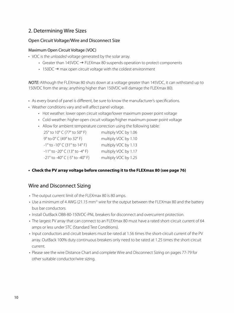
�. Determining Wire Sizes
Open Circuit Voltage/Wire and Disconnect Size
Maximum Open Circuit Voltage (VOC)• VOC is the unloaded voltage generated by the solar array.
• Greater than 145VDC g FLEXmax 80 suspends operation to protect components • 150DC g max open circuit voltage with the coldest environment
NOTE: Although the FLEXmax 80 shuts down at a voltage greater than 145VDC, it can withstand up to 150VDC from the array; anything higher than 150VDC will damage the FLEXmax 80).
• As every brand of panel is different, be sure to know the manufacturer’s specifications.• Weather conditions vary and will affect panel voltage.
• Hot weather: lower open circuit voltage/lower maximum power point voltage • Cold weather: higher open circuit voltage/higher maximum power point voltage • Allow for ambient temperature correction using the following table:
25° to 10° C (77° to 50° F) multiply VOC by 1.06 9° to 0° C (49° to 32° F) multiply VOC by 1.10 -1° to -10° C (31° to 14° F) multiply VOC by 1.13 -11° to -20° C (13° to -4° F) multiply VOC by 1.17 -21° to -40° C (-5° to -40° F) multiply VOC by 1.25
• CheckthePVarrayvoltagebeforeconnectingittotheFLEXmax80(seepage76)
Wire and Disconnect Sizing
• The output current limit of the FLEXmax 80 is 80 amps.• Use a minimum of 4 AWG (21.15 mm2) wire for the output between the FLEXmax 80 and the battery
bus bar conductors.• Install OutBack OBB-80-150VDC-PNL breakers for disconnect and overcurrent protection.• The largest PV array that can connect to an FLEXmax 80 must have a rated short-circuit current of 64
amps or less under STC (Standard Test Conditions).• Input conductors and circuit breakers must be rated at 1.56 times the short-circuit current of the PV
array. OutBack 100% duty continuous breakers only need to be rated at 1.25 times the short-circuit current.
• Please see the wire Distance Chart and complete Wire and Disconnect Sizing on pages 77-79 for other suitable conductor/wire sizing.
��PB
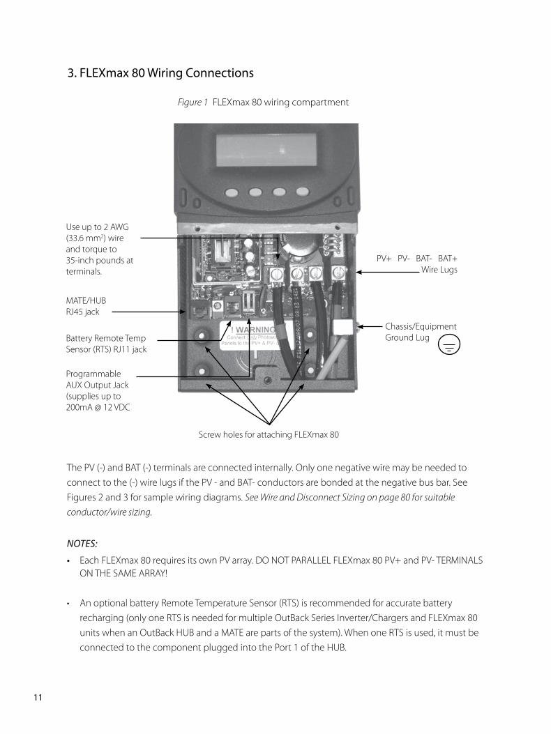
The PV (-) and BAT (-) terminals are connected internally. Only one negative wire may be needed to connect to the (-) wire lugs if the PV - and BAT- conductors are bonded at the negative bus bar. See Figures 2 and 3 for sample wiring diagrams. See Wire and Disconnect Sizing on page 80 for suitable conductor/wire sizing.
NOTES:
• Each FLEXmax 80 requires its own PV array. DO NOT PARALLEL FLEXmax 80 PV+ and PV- TERMINALS ON THE SAME ARRAY!
• An optional battery Remote Temperature Sensor (RTS) is recommended for accurate battery recharging (only one RTS is needed for multiple OutBack Series Inverter/Chargers and FLEXmax 80 units when an OutBack HUB and a MATE are parts of the system). When one RTS is used, it must be connected to the component plugged into the Port 1 of the HUB.
Figure 1 FLEXmax 80 wiring compartment
Programmable AUX Output Jack (supplies up to 200mA @ 12 VDC
Battery Remote Temp Sensor (RTS) RJ11 jack
Use up to 2 AWG (33.6 mm2) wire and torque to 35-inch pounds at terminals.
MATE/HUB RJ45 jack
Chassis/EquipmentGround Lug
PV+ PV- BAT- BAT+Wire Lugs
Screw holes for attaching FLEXmax 80
�. FLEXmax 80 Wiring Connections
��PB
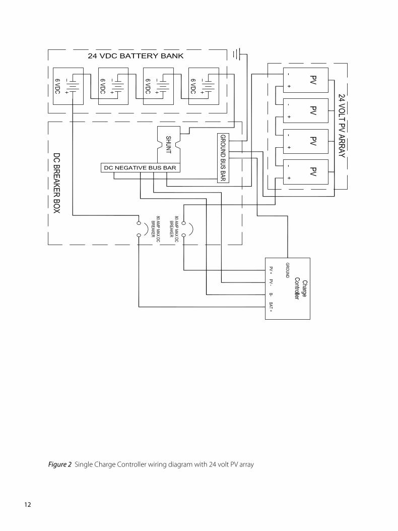
Figure 2 Single Charge Controller wiring diagram with 24 volt PV array
��PB
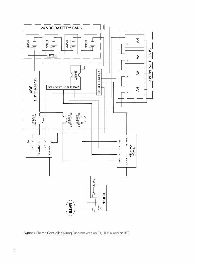
Figure 3 Charge Controller Wiring Diagram with an FX, HUB 4, and an RTS
��PB
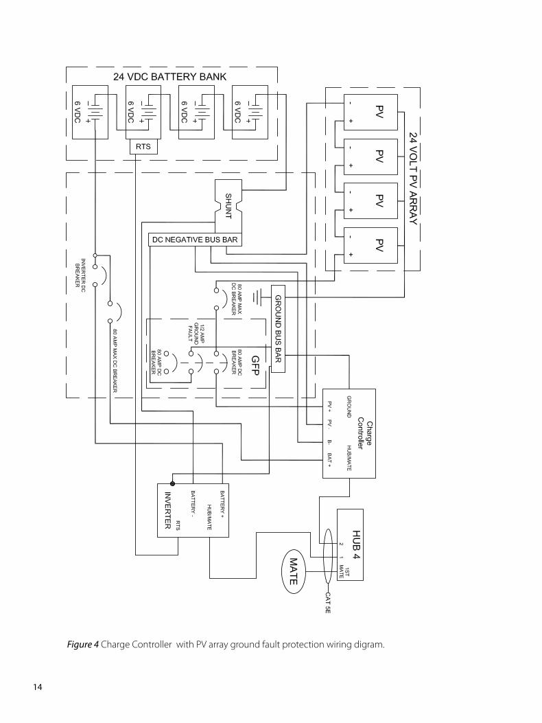
Figure 4 Charge Controller with PV array ground fault protection wiring digram.
��PB
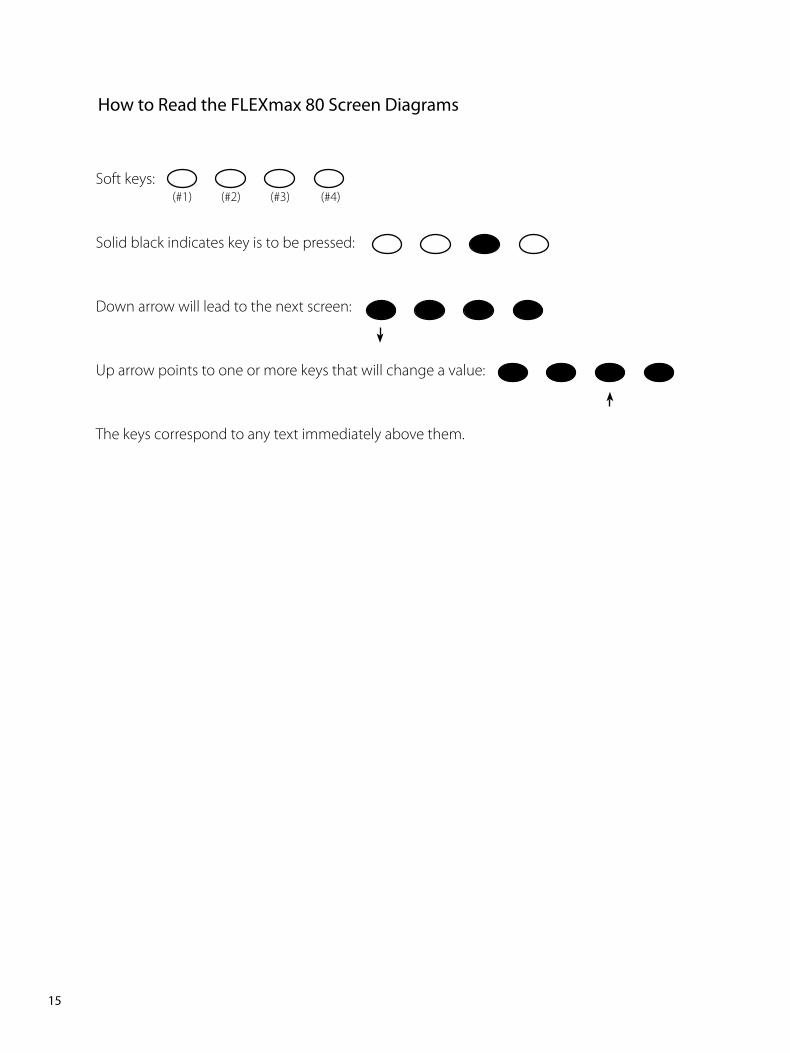
Soft keys:
Solid black indicates key is to be pressed:
Down arrow will lead to the next screen:
Up arrow points to one or more keys that will change a value:
The keys correspond to any text immediately above them.
(#1) (#2) (#3) (#4)
How to Read the FLEXmax 80 Screen Diagrams
��PB
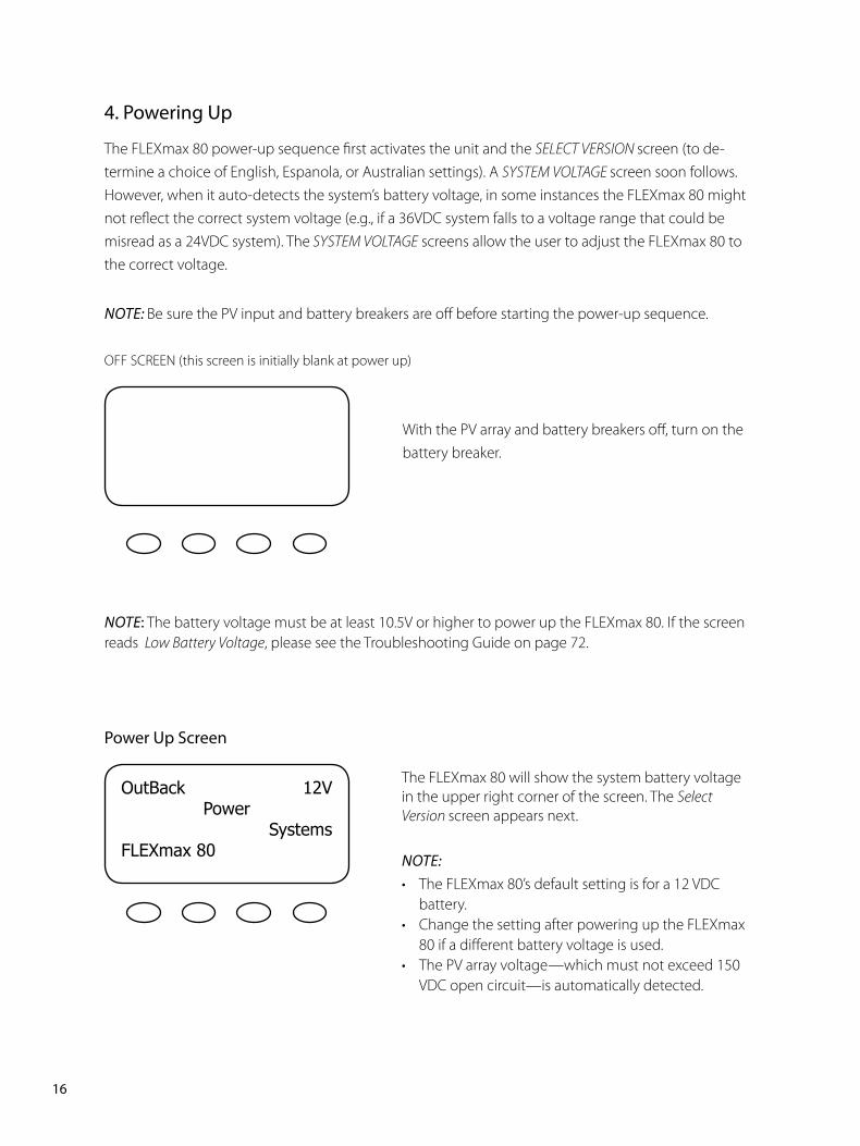
�. Powering Up
The FLEXmax 80 power-up sequence first activates the unit and the SELECT VERSION screen (to de-termine a choice of English, Espanola, or Australian settings). A SYSTEM VOLTAGE screen soon follows. However, when it auto-detects the system’s battery voltage, in some instances the FLEXmax 80 might not reflect the correct system voltage (e.g., if a 36VDC system falls to a voltage range that could be misread as a 24VDC system). The SYSTEM VOLTAGE screens allow the user to adjust the FLEXmax 80 to the correct voltage.
NOTE: Be sure the PV input and battery breakers are off before starting the power-up sequence.
OFF SCREEN (this screen is initially blank at power up)
With the PV array and battery breakers off, turn on the battery breaker.
NOTE: The battery voltage must be at least 10.5V or higher to power up the FLEXmax 80. If the screen reads Low Battery Voltage, please see the Troubleshooting Guide on page 72.
OutBack 12VPower
SystemsFLEXmax80
Power Up Screen
The FLEXmax 80 will show the system battery voltage in the upper right corner of the screen. The Select Version screen appears next.
NOTE:• The FLEXmax 80’s default setting is for a 12 VDC
battery.• Change the setting after powering up the FLEXmax
80 if a different battery voltage is used.• The PV array voltage—which must not exceed 150
VDC open circuit—is automatically detected.
��PB
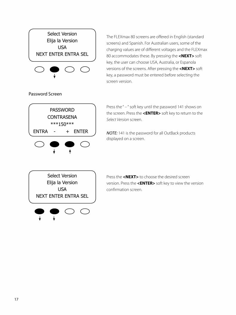
The FLEXmax 80 screens are offered in English (standard screens) and Spanish. For Australian users, some of the charging values are of different voltages and the FLEXmax 80 accommodates these. By pressing the <NEXT> soft key, the user can choose USA, Australia, or Espanola versions of the screens. After pressing the <NEXT> soft key, a password must be entered before selecting the screen version.
Password Screen
Press the “ – “ soft key until the password 141 shows on the screen. Press the <ENTER> soft key to return to the Select Version screen.
NOTE: 141 is the password for all OutBack products displayed on a screen.
Press the <NEXT> to choose the desired screen version. Press the <ENTER> soft key to view the version confirmation screen.
PASSWORDCONTRASENA***150***
ENTRA-+ENTER
SelectVersionElijalaVersion
USANEXTENTERENTRASEL
SelectVersionElijalaVersion
USANEXTENTERENTRASEL
�8PB
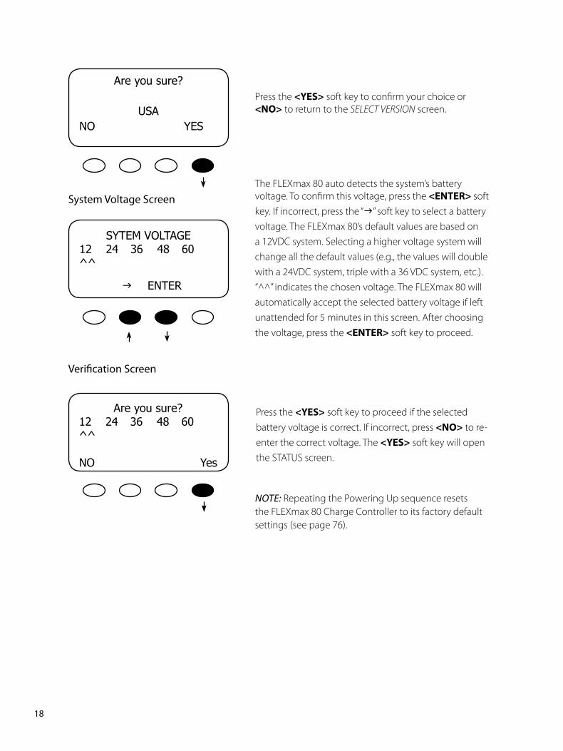
System Voltage Screen
Press the <YES> soft key to proceed if the selected battery voltage is correct. If incorrect, press <NO> to re-enter the correct voltage. The <YES> soft key will open the STATUS screen.
SYTEMVOLTAGE12 24 36 48 60^^
gENTER
Areyousure?12 24 36 48 60^^
NO Yes
NOTE: Repeating the Powering Up sequence resets the FLEXmax 80 Charge Controller to its factory default settings (see page 76).
Areyousure?
USANOYES
Press the <YES> soft key to confirm your choice or <NO> to return to the SELECT VERSION screen.
The FLEXmax 80 auto detects the system’s battery voltage. To confirm this voltage, press the <ENTER>soft key. If incorrect, press the “g” soft key to select a battery voltage. The FLEXmax 80’s default values are based on a 12VDC system. Selecting a higher voltage system will change all the default values (e.g., the values will double with a 24VDC system, triple with a 36 VDC system, etc.). “^^” indicates the chosen voltage. The FLEXmax 80 will automatically accept the selected battery voltage if left unattended for 5 minutes in this screen. After choosing the voltage, press the <ENTER> soft key to proceed.
Verification Screen
��PB
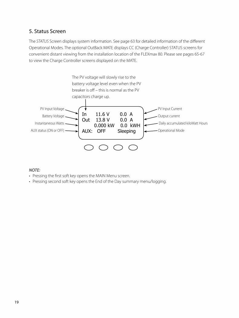
NOTE:• Pressing the first soft key opens the MAIN Menu screen.• Pressing second soft key opens the End of the Day summary menu/logging.
�. Status Screen
The STATUS Screen displays system information. See page 63 for detailed information of the different Operational Modes. The optional OutBack MATE displays CC (Charge Controller) STATUS screens for convenient distant viewing from the installation location of the FLEXmax 80. Please see pages 65-67 to view the Charge Controller screens displayed on the MATE.
The PV voltage will slowly rise to the battery voltage level even when the PV breaker is off – this is normal as the PV capacitors charge up.
PV Input Voltage
Battery Voltage
Instantaneous Watts
AUX status (ON or OFF)
PV Input Current
Output current
Daily accumulated kiloWatt Hours
Operational Mode
In11.6V0.0AOut13.8V0.0A0.000kW0.0kWHAUX:OFFSleeping
�0PB
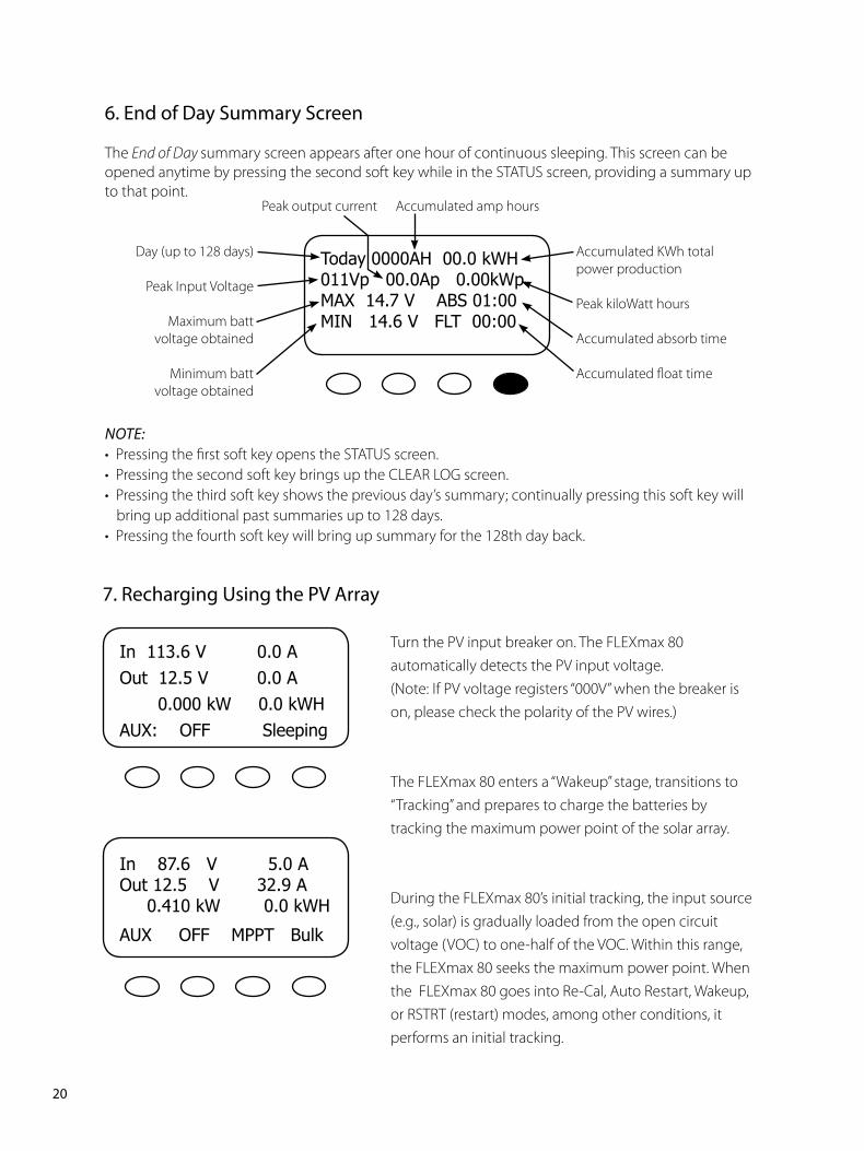
NOTE:• Pressing the first soft key opens the STATUS screen.• Pressing the second soft key brings up the CLEAR LOG screen.• Pressing the third soft key shows the previous day’s summary; continually pressing this soft key will
bring up additional past summaries up to 128 days.• Pressing the fourth soft key will bring up summary for the 128th day back.
�. End of Day Summary Screen
TheEnd of Day summary screen appears after one hour of continuous sleeping. This screen can be opened anytime by pressing the second soft key while in the STATUS screen, providing a summary up to that point.
Today0000AH00.0kWH011Vp00.0Ap0.00kWpMAX14.7VABS01:00MIN14.6VFLT00:00
Accumulated amp hoursPeak output current
Accumulated KWh totalpower production
Peak kiloWatt hours
Accumulated absorb time
Accumulated float time
Day (up to 128 days)
Peak Input Voltage
Maximum batt voltage obtained
Minimum batt voltage obtained
�. Recharging Using the PV Array
Turn the PV input breaker on. The FLEXmax 80 automatically detects the PV input voltage.(Note: If PV voltage registers “000V” when the breaker is on, please check the polarity of the PV wires.)
The FLEXmax 80 enters a “Wakeup” stage, transitions to “Tracking” and prepares to charge the batteries by tracking the maximum power point of the solar array.
During the FLEXmax 80’s initial tracking, the input source (e.g., solar) is gradually loaded from the open circuit voltage (VOC) to one-half of the VOC. Within this range, the FLEXmax 80 seeks the maximum power point. When the FLEXmax 80 goes into Re-Cal, Auto Restart, Wakeup, or RSTRT (restart) modes, among other conditions, it performs an initial tracking.
In113.6V 0.0AOut12.5V 0.0A0.000kW0.0kWHAUX:OFF Sleeping
In87.6V 5.0AOut12.5V32.9A0.410kW0.0kWH
AUXOFFMPPTBulk
��PB
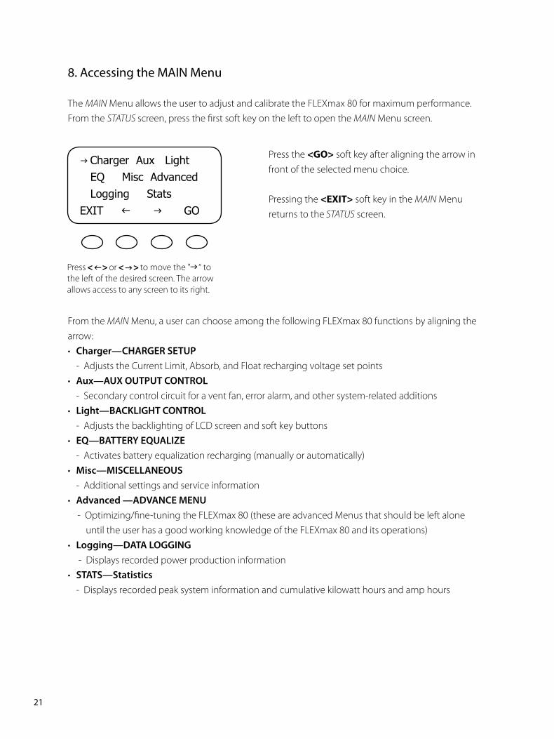
8. Accessing the MAIN Menu
The MAIN Menu allows the user to adjust and calibrate the FLEXmax 80 for maximum performance. From the STATUSscreen, press the first soft key on the left to open the MAIN Menuscreen.
Press the <GO> soft key after aligning the arrow in front of the selected menu choice.
Pressing the <EXIT> soft key in the MAIN Menu returns to the STATUS screen.
From the MAIN Menu, a user can choose among the following FLEXmax 80 functions by aligning the arrow:• Charger—CHARGER SETUP - Adjusts the Current Limit, Absorb, and Float recharging voltage set points• Aux—AUX OUTPUT CONTROL - Secondary control circuit for a vent fan, error alarm, and other system-related additions• Light—BACKLIGHT CONTROL - Adjusts the backlighting of LCD screen and soft key buttons• EQ—BATTERY EQUALIZE - Activates battery equalization recharging (manually or automatically)• Misc—MISCELLANEOUS - Additional settings and service information• Advanced —ADVANCE MENU - Optimizing/fine-tuning the FLEXmax 80 (these are advanced Menus that should be left alone until the user has a good working knowledge of the FLEXmax 80 and its operations)• Logging—DATA LOGGING - Displays recorded power production information• STATS—Statistics - Displays recorded peak system information and cumulative kilowatt hours and amp hours
g ChargerAuxLightEQMiscAdvancedLoggingStatsEXITfg GO
Press or to move the " “ to the left of the desired screen. The arrow allows access to any screen to its right.
��PB
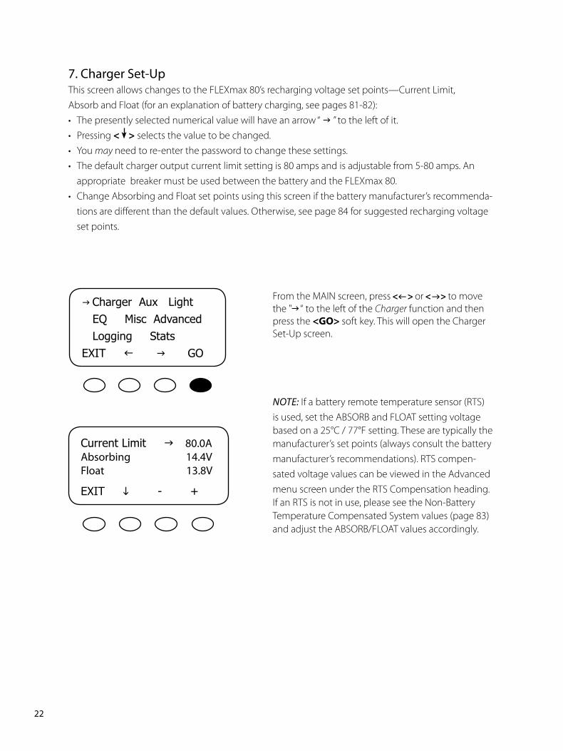
�. Charger Set-UpThis screen allows changes to the FLEXmax 80’s recharging voltage set points—Current Limit, Absorb and Float (for an explanation of battery charging, see pages 81-82):• The presently selected numerical value will have an arrow “ g ” to the left of it.• Pressing < > selects the value to be changed.• You may need to re-enter the password to change these settings.• The default charger output current limit setting is 80 amps and is adjustable from 5-80 amps. An appropriate breaker must be used between the battery and the FLEXmax 80.• Change Absorbing and Float set points using this screen if the battery manufacturer’s recommenda-
tions are different than the default values. Otherwise, see page 84 for suggested recharging voltage set points.
From the MAIN screen, press or to move the " “ to the left of the Charger function and then press the <GO>soft key. This will open the Charger Set-Up screen.
NOTE: If a battery remote temperature sensor (RTS) is used, set the ABSORB and FLOAT setting voltage based on a 25°C / 77°F setting. These are typically the manufacturer’s set points (always consult the battery manufacturer’s recommendations). RTS compen-sated voltage values can be viewed in the Advanced menu screen under the RTS Compensation heading.If an RTS is not in use, please see the Non-Battery Temperature Compensated System values (page 83) and adjust the ABSORB/FLOAT values accordingly.
CurrentLimitg80.0AAbsorbing ��.�VFloat ��.8V
EXITi- +
g ChargerAuxLightEQMiscAdvancedLoggingStatsEXITfg GO
��PB
8. AUX Mode and Its Functions
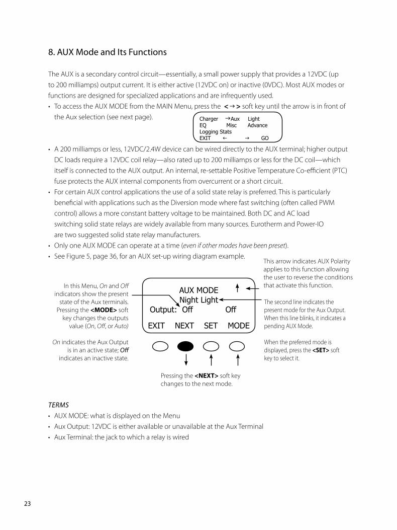
The AUX is a secondary control circuit—essentially, a small power supply that provides a 12VDC (up to 200 milliamps) output current. It is either active (12VDC on) or inactive (0VDC). Most AUX modes or functions are designed for specialized applications and are infrequently used.• To access the AUX MODE from the MAIN Menu, press the < > soft key until the arrow is in front of
the Aux selection (see next page).
• A 200 milliamps or less, 12VDC/2.4W device can be wired directly to the AUX terminal; higher output DC loads require a 12VDC coil relay—also rated up to 200 milliamps or less for the DC coil—which itself is connected to the AUX output. An internal, re-settable Positive Temperature Co-efficient (PTC) fuse protects the AUX internal components from overcurrent or a short circuit.
• For certain AUX control applications the use of a solid state relay is preferred. This is particularly beneficial with applications such as the Diversion mode where fast switching (often called PWM control) allows a more constant battery voltage to be maintained. Both DC and AC load switching solid state relays are widely available from many sources. Eurotherm and Power-IO are two suggested solid state relay manufacturers.
• Only one AUX MODE can operate at a time (even if other modes have been preset).• See Figure 5, page 36, for an AUX set-up wiring diagram example.
In this Menu, On and Off indicators show the present
state of the Aux terminals. Pressing the <MODE> soft
key changes the outputs value (On, Off, or Auto)
On indicates the Aux Output is in an active state; Off
indicates an inactive state.
The second line indicates the present mode for the Aux Output. When this line blinks, it indicates a pending AUX Mode.
When the preferred mode is displayed, press the <SET> soft key to select it.
Pressing the <NEXT> soft key changes to the next mode.
TErmS• AUX MODE: what is displayed on the Menu• Aux Output: 12VDC is either available or unavailable at the Aux Terminal• Aux Terminal: the jack to which a relay is wired
AUXMODENightLight
Output:OffOff
EXITNEXTSETMODE
ChargergAuxLightEQMisc AdvanceLoggingStatsEXITf gGO
This arrow indicates AUX Polarity applies to this function allowing the user to reverse the conditions that activate this function.
��PB
AUX MODE Menu Path
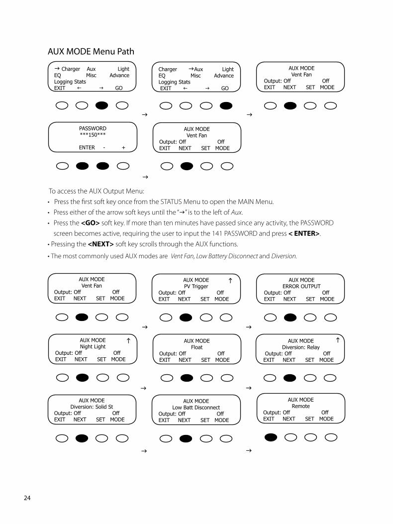
To access the AUX Output Menu:• Press the first soft key once from the STATUS Menu to open the MAIN Menu.• Press either of the arrow soft keys until the “g” is to the left of Aux.• Press the <GO> soft key. If more than ten minutes have passed since any activity, the PASSWORD
screen becomes active, requiring the user to input the 141 PASSWORD and press <ENTER>. • Pressing the <NEXT> soft key scrolls through the AUX functions.
• The most commonly used AUX modes are Vent Fan, Low Battery Disconnect and Diversion.
g Charger Aux LightEQ Misc AdvanceLoggingStatsEXITf gGO
Charger gAux LightEQ Misc AdvanceLoggingStatsEXITf gGO
AUXMODEVentFan
Output:OffOffEXITNEXTSETMODE
PASSWORD***150***
ENTER-+
AUXMODEVentFan
Output:OffOffEXITNEXTSETMODE
g g
AUXMODERemote
Output:OffOffEXITNEXTSETMODE
AUXMODEVentFan
Output:OffOffEXITNEXTSETMODE
AUXMODEPVTrigger
Output:OffOffEXITNEXTSETMODE
AUXMODEERROROUTPUT
Output:OffOffEXITNEXTSETMODE
AUXMODENightLight
Output:OffOffEXITNEXTSETMODE
AUXMODEFloat
Output:OffOffEXITNEXTSETMODE
AUXMODEDiversion:Relay
Output:OffOffEXITNEXTSETMODE
AUXMODEDiversion:SolidSt
Output:OffOffEXITNEXTSETMODE
AUXMODELowBattDisconnect
Output:OffOffEXITNEXTSETMODE
g g
g g
g
g g
g
g g
��PB
AUX modes in order of appearance on the FLEXmax 80 display:• Vent Fan • PV Trigger • Error Output • Night Light • Float • Diversion Relay
• Diversion Solid State • Low Battery Disconnect • Remote
When an AUX MODE is in AUTO, 12VDC is available at the AUX terminals and a condition, such as a voltage
set point, is met. Other modes can be programmed in lieu of the specific ones listed here, but the Vent Fan
mode is most easily changed (e.g., to activate an alarm instead of a fan). Here are the default AUX modes:
• Vent Fan— when the Vent Fan voltage set point is exceeded, the vent fan will run for at least 15 seconds
(the fan helps remove hydrogen from battery enclosure), even if the set point is exceeded for only a few
seconds due to a surge. If the set point is exceeded for longer than 15 seconds, the fan will stay on until
the voltage drops below the set point. It then takes 15 seconds before the fan shuts off. This is an optional
external fan and not to be confused with the FLEXmax 80’s internal, thermally activated fan which cools
the unit.
• PV Trigger*—activates an alarm or relay (that disconnects the array); when the PV input exceeds the
user-determined voltage set point (to avoid damage, do not go over 150VDC), the PV Trigger disconnects
after a minimal adjustable amount of Hold Time.
• Error Output—useful for monitoring remote sites, switches to the Off state if the FLEXmax 80 has not
charged the batteries for 26 hours or more (not an audible alarm, only displayed as a printed message
on FLEXmax 80 AUX Menu) or the battery voltage has fallen below a user-determined set point for 10
continuous minutes. In the No Error state, the AUX output is on.
• Night Light*—after the PV voltage is below a threshold voltage for a user-determined time period, a
user-provided light illuminates as long as the FLEXmax 80 remains sleeping or as determined by the
user-established time limit.
• Float—powers a load if the FLEXmax 80 is producing power in the Float stage
• Diversion Relay*—diverts excess power away from batteries when a wind or hydro generator is
connected directly to the batteries.
• Diversion Solid St—same as Diversion Relay, but applies when a solid state relay is used rather than a
mechanical relay
• Low Batt Disconnect—activates/deactivates the AUX load(s) when a user-determined voltage and time
levels are reached.
• Remote—allows OutBack MATE control of the AUX MODE (see MATE manual for details).
* These functions support AUX polarity.
NOTE: All AUX functions can be manually activated in On, Off, or Auto mode. In Auto mode, the function will automatically activate when a user-determined value is met and deactivate or shut down when other conditions described here, such as a certain amount of time passing, occur.
��PB
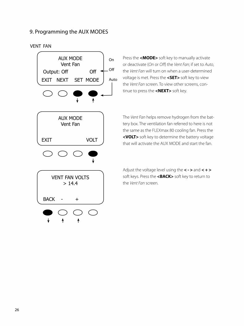
VENT FAN
Press the <MODE> soft key to manually activate or deactivate (On or Off) the Vent Fan; if set to Auto, the Vent Fan will turn on when a user-determined voltage is met. Press the <SET>soft key to view the Vent Fan screen. To view other screens, con-tinue to press the <NEXT> soft key.
The Vent Fan helps remove hydrogen from the bat-tery box. The ventilation fan referred to here is not the same as the FLEXmax 80 cooling fan. Press the <VOLT> soft key to determine the battery voltage that will activate the AUX MODE and start the fan.
Adjust the voltage level using the <->and <+> soft keys. Press the <BACK> soft key to return to the Vent Fan screen.
AUXMODEVentFan
Output:OffOff
EXITNEXTSET MODE
AUXMODEVentFan
EXIT VOLT
VENTFANVOLTS>14.4
BACK-+
On
Off
Auto
�. Programming the AUX MODES
��PB
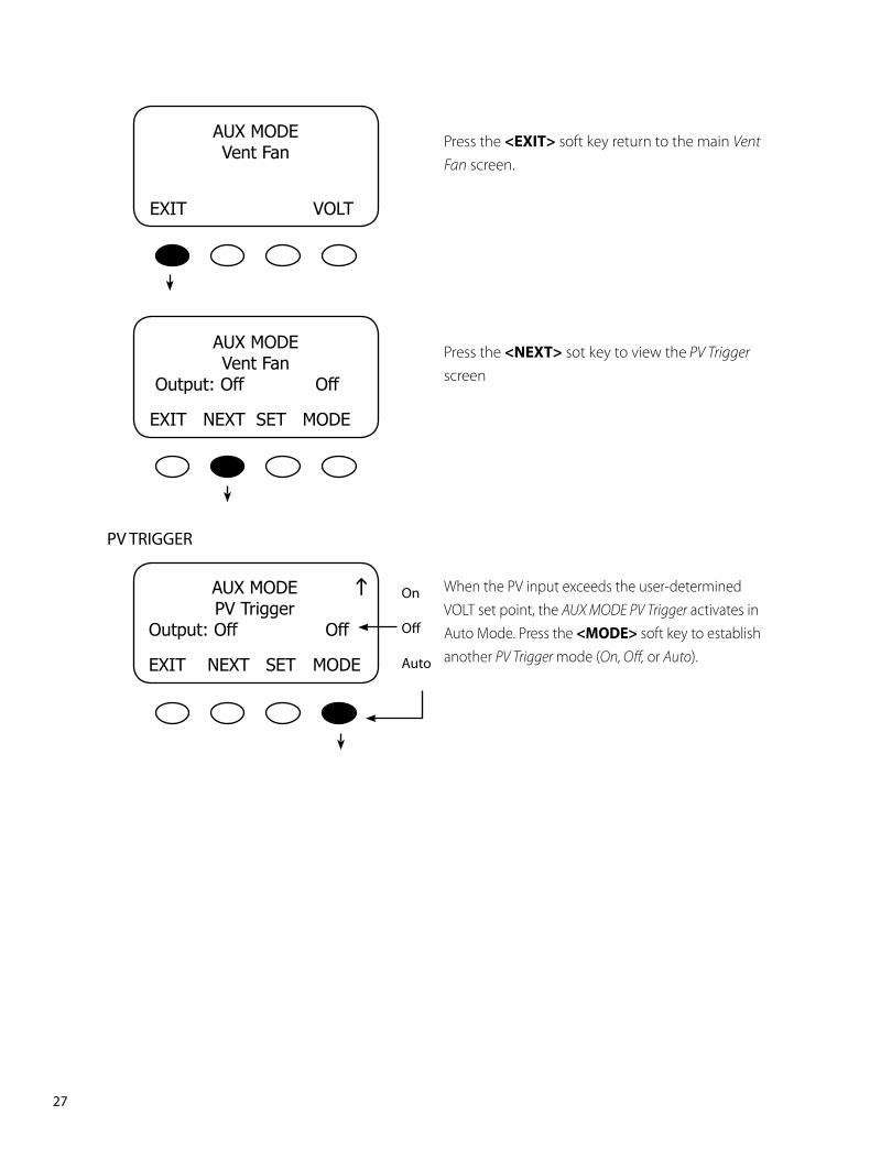
Press the <EXIT> soft key return to the main Vent Fan screen.
Press the <NEXT> sot key to view the PV Trigger screen
When the PV input exceeds the user-determined VOLT set point, the AUX MODE PV Trigger activates in Auto Mode. Press the <MODE> soft key to establish another PV Trigger mode (On, Off, or Auto).
AUXMODEVentFan
EXITVOLT
AUXMODEVentFan
Output:OffOff
EXITNEXTSETMODE
AUXMODEPVTrigger
Output:OffOff
EXITNEXTSET MODE
On
Off
Auto
PV TRIGGER
g
�8PB
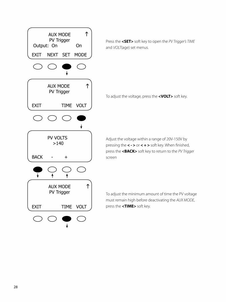
Press the <SET> soft key to open the PV Trigger’s TIME and VOLT(age) set menus.
To adjust the voltage, press the <VOLT> soft key.
Adjust the voltage within a range of 20V-150V by pressing the <->or <+>soft key. When finished, press the <BACK> soft key to return to the PV Trigger screen
To adjust the minimum amount of time the PV voltage must remain high before deactivating the AUX MODE, press the <TIME>soft key.
AUXMODEPVTrigger
Output:OnOn
EXITNEXTSETMODE
PVVOLTS >140
BACK-+
AUXMODEPVTrigger
EXITTIMEVOLT
AUXMODEPVTrigger
EXITTIMEVOLT
gg
g
��PB
HoldTimeSec01.1
BACK-+
AUXMODEPVTriggerOutput:OnOnEXITNEXTSETMODE
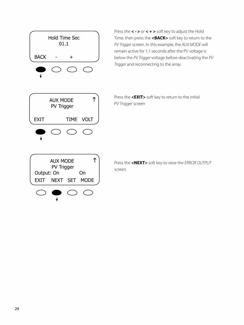
Press the <-> or <+> soft key to adjust the Hold Time, then press the <BACK> soft key to return to the PV Trigger screen. In this example, the AUX MODE will remain active for 1.1 seconds after the PV voltage is below the PV Trigger voltage before deactivating the PV Trigger and reconnecting to the array.
Press the <EXIT> soft key to return to the initial PV Trigger screen
Press the <NEXT> soft key to view the ERROR OUTPUT screen.
gAUXMODEPVTrigger
EXITTIMEVOLT
g
�0PB
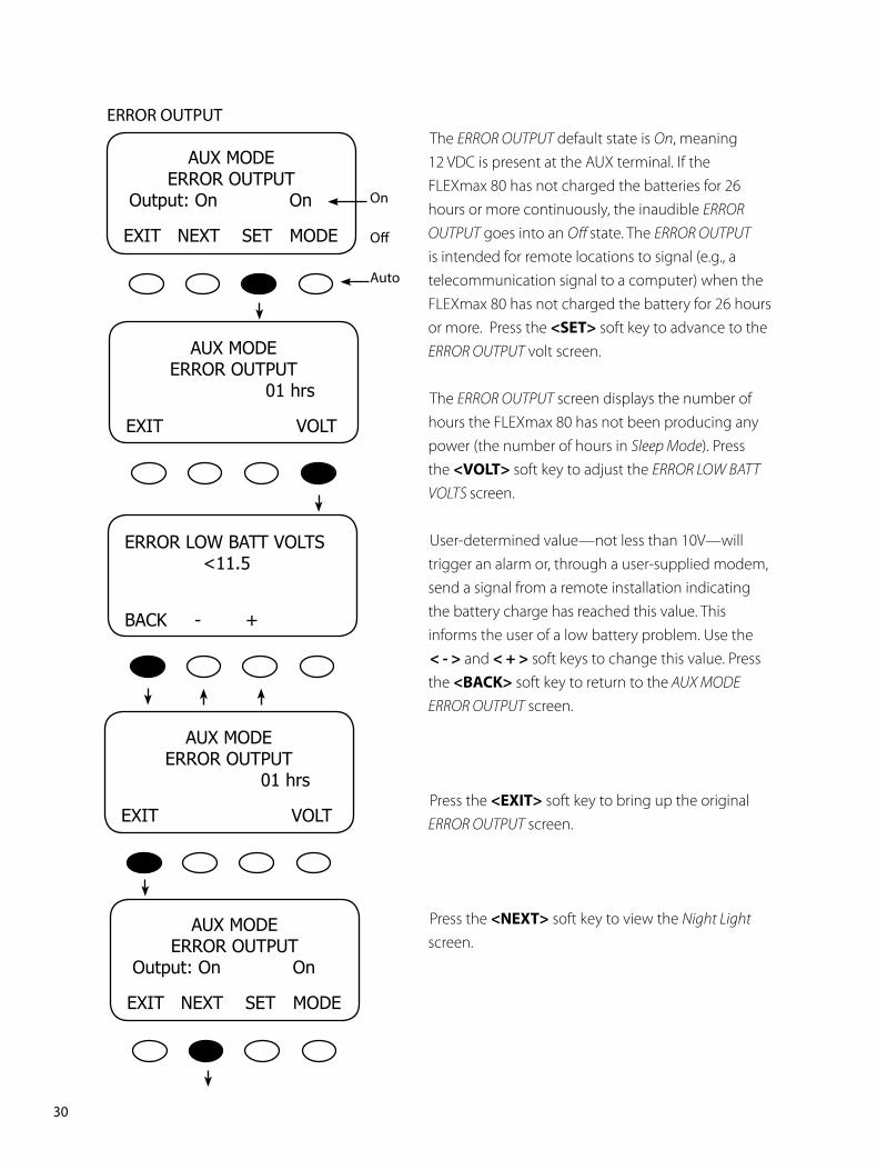
The ERROR OUTPUT default state is On, meaning 12 VDC is present at the AUX terminal. If the FLEXmax 80 has not charged the batteries for 26 hours or more continuously, the inaudible ERROR OUTPUT goes into an Off state. The ERROR OUTPUT is intended for remote locations to signal (e.g., a telecommunication signal to a computer) when the FLEXmax 80 has not charged the battery for 26 hours or more. Press the <SET> soft key to advance to the ERROR OUTPUT volt screen.
The ERROR OUTPUT screen displays the number of hours the FLEXmax 80 has not been producing any power (the number of hours in Sleep Mode). Press the <VOLT> soft key to adjust the ERROR LOW BATT VOLTS screen.
User-determined value—not less than 10V—will trigger an alarm or, through a user-supplied modem, send a signal from a remote installation indicating the battery charge has reached this value. This informs the user of a low battery problem. Use the<-> and <+> soft keys to change this value. Press the <BACK> soft key to return to the AUX MODE ERROR OUTPUT screen.
Press the <EXIT> soft key to bring up the original ERROR OUTPUT screen.
Press the <NEXT> soft key to view the Night Light screen.
AUXMODEERROROUTPUT
Output:OnOn
EXITNEXTSETMODE
On
Off
Auto
AUXMODEERROROUTPUT
01hrs
EXITVOLT
ERRORLOWBATTVOLTS <11.5
BACK-+
AUXMODEERROROUTPUT
01hrs
EXITVOLT
ERROR OUTPUT
AUXMODEERROROUTPUT
Output:OnOn
EXITNEXTSETMODE
��PB
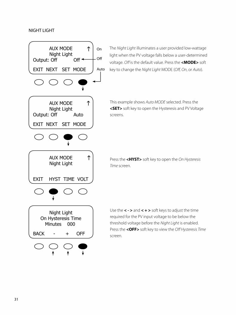
This example shows Auto MODE selected. Press the <SET> soft key to open the Hysteresis and PV Voltage screens.
Press the <HYST> soft key to open the On Hysteresis Time screen.
Use the <-> and <+> soft keys to adjust the time required for the PV input voltage to be below the threshold voltage before the Night Light is enabled. Press the <OFF>soft key to view the Off Hysteresis Time screen.
AUXMODENightLight
Output:OffOff
EXITNEXTSETMODE
On
Off
Auto
AUXMODENightLight
Output:OffAuto
EXITNEXTSETMODE
AUXMODENightLight
EXITHYSTTIMEVOLT
NightLightOnHysteresisTime
Minutes000
BACK-+OFF
The Night Light illuminates a user provided low-wattage
light when the PV voltage falls below a user-determined
voltage. Off is the default value. Press the <MODE> soft
key to change the Night Light MODE (Off, On, or Auto).
NIGHT LIGHT
gg
g
��PB
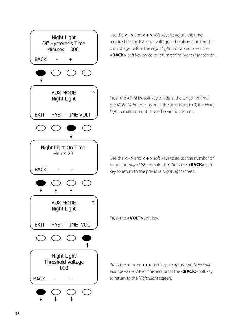
Press the <TIME> soft key to adjust the length of time the Night Light remains on. If the time is set to 0, the Night Light remains on until the off condition is met.
Use the <-> and <+> soft keys to adjust the number of hours the Night Light remains on. Press the <BACK> soft key to return to the previous Night Light screen.
Press the <VOLT> soft key.
Press the <-> or <+>soft keys to adjust the Threshold Voltage value. When finished, press the <BACK> soft key to return to the Night Light screen.
AUXMODENightLight
EXITHYSTTIMEVOLT
NightLightThresholdVoltage
010
BACK-+
AUXMODENightLight
EXITHYSTTIMEVOLT
NightLightOnTimeHours23
BACK-+
NightLightOffHysteresisTime
Minutes000
BACK-+
Use the <-> and <+> soft keys to adjust the time required for the PV input voltage to be above the thresh-old voltage before the Night Light is disabled. Press the <BACK> soft key twice to return to the Night Light screen.
gg
��PB
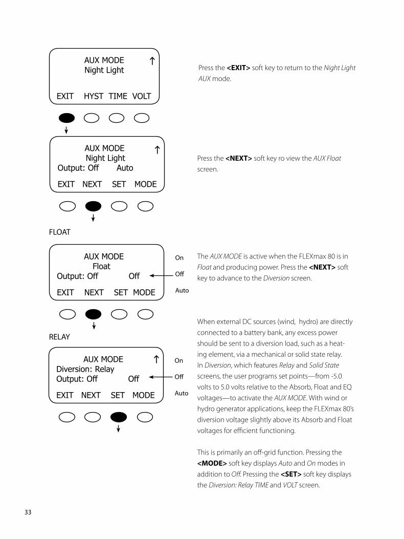
Press the <NEXT> soft key ro view the AUX Float screen.
The AUX MODE is active when the FLEXmax 80 is in Float and producing power. Press the<NEXT> softkey to advance to the Diversion screen.
When external DC sources (wind, hydro) are directly connected to a battery bank, any excess power should be sent to a diversion load, such as a heat-ing element, via a mechanical or solid state relay. In Diversion, which features Relay and Solid State screens, the user programs set points—from -5.0 volts to 5.0 volts relative to the Absorb, Float and EQ voltages—to activate the AUX MODE. With wind or hydro generator applications, keep the FLEXmax 80’s diversion voltage slightly above its Absorb and Float voltages for efficient functioning.
This is primarily an off-grid function. Pressing the<MODE> soft key displays Auto and On modes inaddition to Off. Pressing the <SET>soft key displaysthe Diversion: Relay TIME and VOLT screen.
AUXMODENightLightOutput:OffAuto
EXITNEXTSETMODE
FLOAT
AUXMODEFloatOutput:OffOff
EXITNEXTSETMODE
On
Off
Auto
RELAY
AUXMODEDiversion:RelayOutput:OffOff
EXITNEXTSETMODE
On
Off
Auto
AUXMODENightLight
EXITHYSTTIMEVOLT
Press the <EXIT> soft key to return to the Night Light AUX mode.
gg
g
��PB
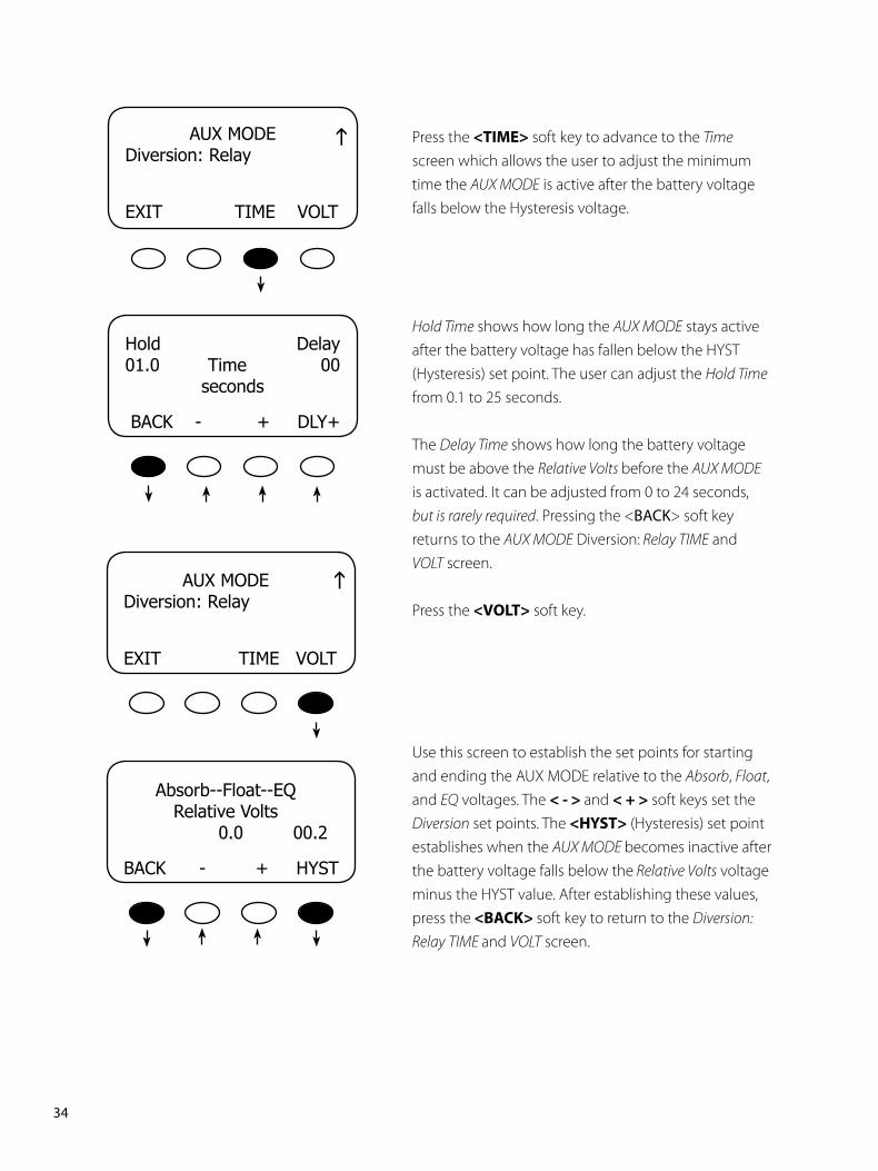
Press the <TIME> soft key to advance to the Time screen which allows the user to adjust the minimum time the AUX MODE is active after the battery voltage falls below the Hysteresis voltage.
Hold Time shows how long the AUX MODE stays active after the battery voltage has fallen below the HYST (Hysteresis) set point. The user can adjust the Hold Time from 0.1 to 25 seconds.
The Delay Time shows how long the battery voltage must be above the Relative Volts before the AUX MODE is activated. It can be adjusted from 0 to 24 seconds, but is rarely required. Pressing the <BACK> soft key returns to the AUX MODE Diversion: Relay TIME and VOLT screen.
Press the <VOLT> soft key.
Use this screen to establish the set points for starting and ending the AUX MODE relative to the Absorb, Float, and EQ voltages. The <->and <+> soft keys set the Diversion set points. The <HYST> (Hysteresis) set point establishes when the AUX MODE becomes inactive after the battery voltage falls below the Relative Volts voltage minus the HYST value. After establishing these values, press the<BACK>soft key to return to the Diversion: Relay TIME and VOLT screen.
AUXMODEDiversion:Relay
EXITTIMEVOLT
Hold Delay01.0 Time 00
seconds
BACK-+DLY+
AUXMODEDiversion:Relay
EXITTIMEVOLT
Absorb--Float--EQ RelativeVolts0.000.2
BACK-+HYST
gg
��PB
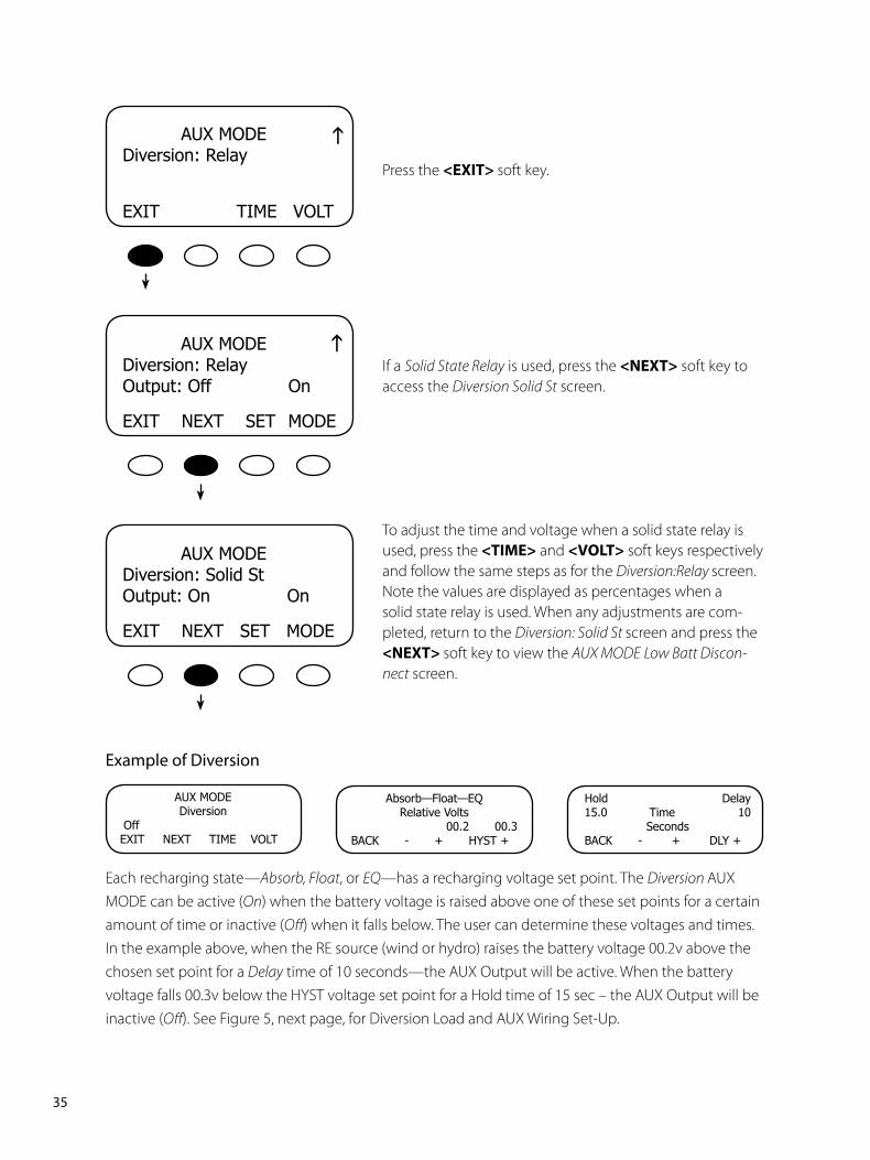
Example of Diversion
Each recharging state—Absorb, Float, or EQ—has a recharging voltage set point. The Diversion AUX MODE can be active (On) when the battery voltage is raised above one of these set points for a certain amount of time or inactive (Off) when it falls below. The user can determine these voltages and times. In the example above, when the RE source (wind or hydro) raises the battery voltage 00.2v above the chosen set point for a Delay time of 10 seconds—the AUX Output will be active. When the battery voltage falls 00.3v below the HYST voltage set point for a Hold time of 15 sec – the AUX Output will be inactive (Off). See Figure 5, next page, for Diversion Load and AUX Wiring Set-Up.
AUXMODEDiversion
OffEXITNEXTTIMEVOLT
Absorb—Float—EQRelativeVolts
00.200.3BACK-+HYST+
Hold Delay15.0 Time 10
SecondsBACK-+DLY+
AUXMODEDiversion:Relay
EXITTIMEVOLT
Press the <EXIT>soft key.
If a Solid State Relay is used, press the <NEXT> soft key to access the Diversion Solid St screen.
To adjust the time and voltage when a solid state relay is used, press the <TIME> and <VOLT> soft keys respectively and follow the same steps as for the Diversion:Relay screen. Note the values are displayed as percentages when a solid state relay is used. When any adjustments are com-pleted, return to the Diversion: Solid St screen and press the <NEXT>soft key to view the AUX MODE Low Batt Discon-nect screen.
AUXMODEDiversion:RelayOutput:OffOn
EXITNEXTSETMODE
AUXMODEDiversion:SolidStOutput:OnOn
EXITNEXTSETMODE
gg

��PB
Figure 5 Diversion Load and AUX Wiring Set-Up Illustrated
��PB
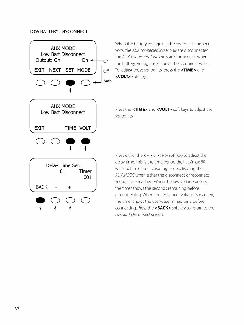
LOW BATTERY DISCONNECT
When the battery voltage falls below the disconnect volts, the AUX connected loads only are disconnected; the AUX connected loads only are connected when the battery voltage rises above the reconnect volts. To adjust these set points, press the <TIME> and <VOLT> soft keys.
Press the <TIME>and <VOLT> soft keys to adjust the set points.
Press either the<-> or <+> soft key to adjust the delay time. This is the time period the FLEXmax 80 waits before either activating or deactivating the AUX MODE when either the disconnect or reconnect voltages are reached. When the low voltage occurs, the timer shows the seconds remaining before disconnecting. When the reconnect voltage is reached, the timer shows the user-determined time before connecting. Press the<BACK> soft key to return to the Low Batt Disconnect screen.
DelayTimeSec 01 Timer 001
BACK-+
AUXMODELowBattDisconnect
Output:OnOn
EXITNEXTSETMODE
AUXMODELowBattDisconnect
EXITTIMEVOLT
On
Off
Auto
�8PB
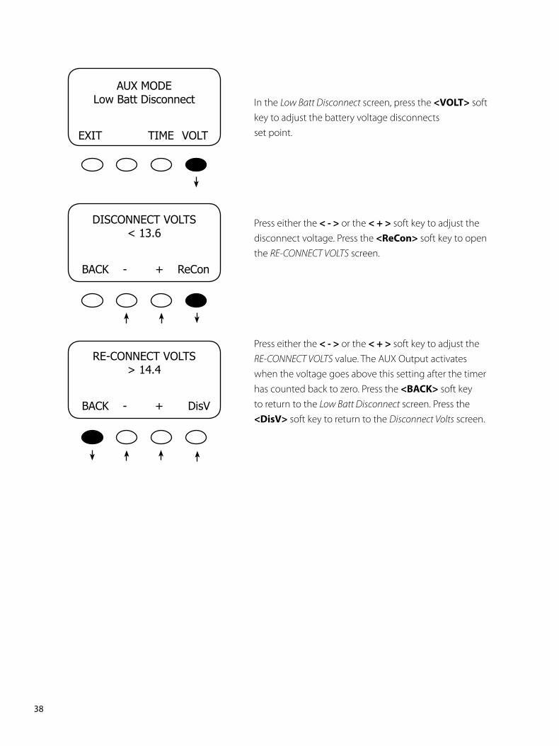
In the Low Batt Disconnect screen, press the <VOLT> soft key to adjust the battery voltage disconnects set point.
Press either the <-> or the <+> soft key to adjust the disconnect voltage. Press the <ReCon> soft key to open the RE-CONNECT VOLTS screen.
Press either the <-> or the <+> soft key to adjust the RE-CONNECT VOLTS value. The AUX Output activates when the voltage goes above this setting after the timer has counted back to zero. Press the <BACK> soft key to return to the Low Batt Disconnect screen. Press the <DisV> soft key to return to the Disconnect Volts screen.
AUXMODELowBattDisconnect
EXITTIMEVOLT
DISCONNECTVOLTS<13.6
BACK-+ReCon
RE-CONNECTVOLTS>14.4
BACK-+DisV
��PB
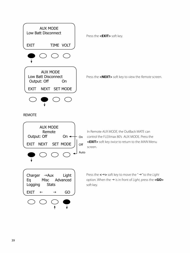
REMOTE
AUXMODELowBattDisconnect
EXITTIMEVOLT
Press the <EXIT> soft key.
Press the <NEXT> soft key to view the Remote screen.
Press the <g> soft key to move the ” g” to the Light option. When the g is in front of Light, press the <GO> soft key.
Charger gAux LightEq MiscAdvancedLoggingStats
EXITf gGO
AUXMODERemote
Output:OffOn
EXITNEXTSET MODE
On
Off
Auto
In Remote AUX MODE, the OutBack MATE can control the FLEXmax 80’s AUX MODE. Press the <EXIT> soft key twice to return to the MAIN Menu screen.
AUXMODELowBattDisconnectOutput:OffOn
EXITNEXTSETMODE
�0PB
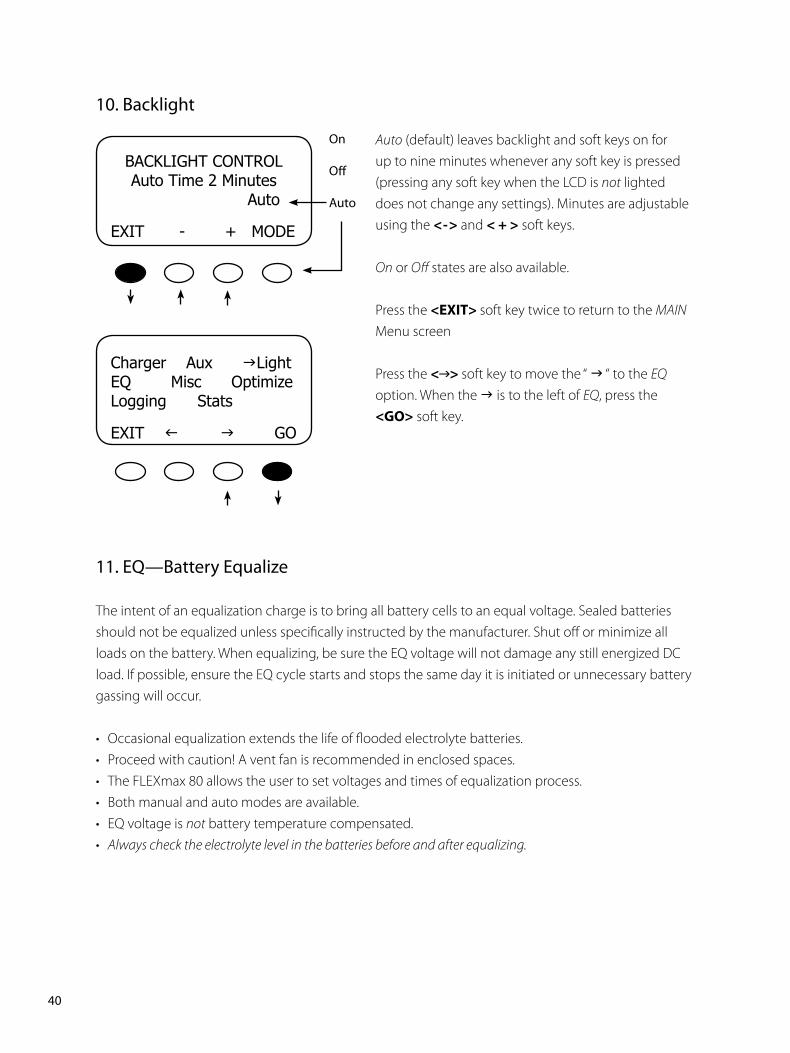
Auto (default) leaves backlight and soft keys on for up to nine minutes whenever any soft key is pressed (pressing any soft key when the LCD is not lighted does not change any settings). Minutes are adjustable using the <-> and <+> soft keys.
On or Off states are also available.
Press the <EXIT>soft key twice to return to the MAIN Menu screen
Press the < >soft key to move the “ g “ to the EQ option. When the g is to the left of EQ, press the <GO> soft key.
ChargerAuxgLightEQMiscOptimizeLoggingStats
EXITf gGO
BACKLIGHTCONTROLAutoTime2MinutesAuto
EXIT-+MODE
On
Off
Auto
�0. Backlight
��. EQ—Battery Equalize
The intent of an equalization charge is to bring all battery cells to an equal voltage. Sealed batteries should not be equalized unless specifically instructed by the manufacturer. Shut off or minimize all loads on the battery. When equalizing, be sure the EQ voltage will not damage any still energized DC load. If possible, ensure the EQ cycle starts and stops the same day it is initiated or unnecessary battery gassing will occur.
• Occasional equalization extends the life of flooded electrolyte batteries.• Proceed with caution! A vent fan is recommended in enclosed spaces.• The FLEXmax 80 allows the user to set voltages and times of equalization process.• Both manual and auto modes are available.• EQ voltage is not battery temperature compensated.• Always check the electrolyte level in the batteries before and after equalizing.

��PB
Press either the <–EQV> or <+EQV> soft key to change the EQ voltage, following your battery manufacturer’s recommendations. Note that the factory default EQ voltage is set low, the same as the factory default Absorb voltage. Press the <NEXT> soft key to view the BATTERY EQUALIZE Time screen.
Press either the <-HRS> or <+HRS> soft key to set the desired equalization time, up to a seven hour maximum, always following your battery manufacturer’s recommendations. Press the <NEXT> soft key to view the battery equalization start screen.
Manual Mode (default mode)
• Press the <START> soft key to manually begin an equalization cycle. To stop the cycle, press the <STOP> soft key.
• EQ-MPPT display indicates the FLEXmax 80 is trying to reach the target equalize set point.
• Equalize time EQ 0:00 in Hours:Minutes displays after the equalize set point is reached.
• The incomplete equalization cycle continues into the next day unless the FLEXmax 80 is powered off or manually stopped. The remaining EQ time can be viewed in the Stats menu.
• EQ cycle terminates when EQ time period is reached.• After equalizing, an EQ DONE message displayed and
a Float cycle begins. This message remains displayed until a soft key is pressed.
Press the <AUTO> soft key to view the auto equalization screen.
BATTERYEQUALIZETime
01Hours
EXITNEXT-HRS+HRS
BATTERYEQUALIZEVolts15.0
EXITNEXT-EQV+EQV
BATTERYEQUALIZE1Hours15.0Volts
Checkwaterlevel
BACKAUTOSTARTSTOP
��PB
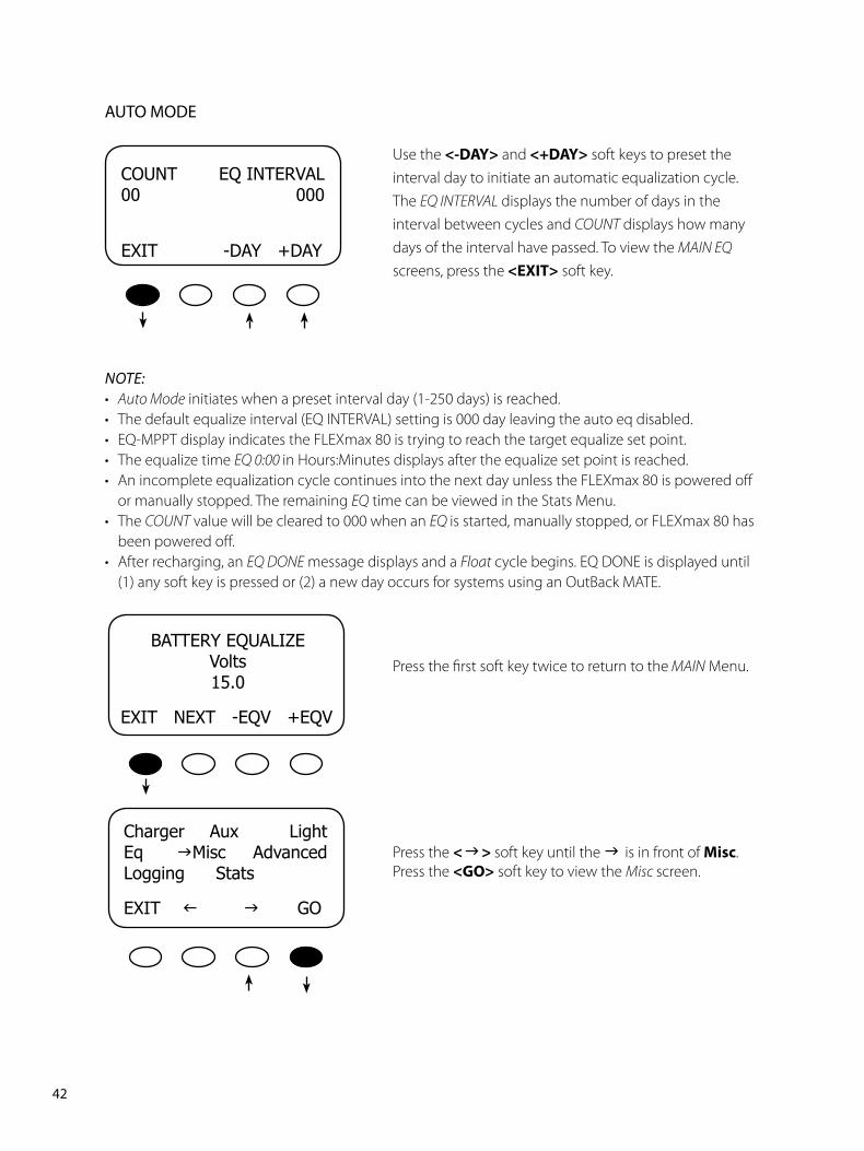
Use the <-DAY> and<+DAY> soft keys to preset the interval day to initiate an automatic equalization cycle. The EQ INTERVAL displays the number of days in the interval between cycles and COUNT displays how many days of the interval have passed. To view the MAIN EQ screens, press the<EXIT> soft key.
Press the first soft key twice to return to the MAIN Menu.
Press the < >soft key until the gis in front of Misc. Press the <GO> soft key to view the Misc screen.
NOTE:• Auto Mode initiates when a preset interval day (1-250 days) is reached.• The default equalize interval (EQ INTERVAL) setting is 000 day leaving the auto eq disabled.• EQ-MPPT display indicates the FLEXmax 80 is trying to reach the target equalize set point.• The equalize time EQ 0:00 in Hours:Minutes displays after the equalize set point is reached.• An incomplete equalization cycle continues into the next day unless the FLEXmax 80 is powered off
or manually stopped. The remaining EQ time can be viewed in the Stats Menu.• The COUNT value will be cleared to 000 when an EQ is started, manually stopped, or FLEXmax 80 has
been powered off.• After recharging, an EQ DONE message displays and a Float cycle begins. EQ DONE is displayed until
(1) any soft key is pressed or (2) a new day occurs for systems using an OutBack MATE.
COUNT EQINTERVAL00 000
EXIT-DAY+DAY
BATTERYEQUALIZEVolts15.0
EXITNEXT-EQV+EQV
AUTO MODE
Charger Aux LightEq gMiscAdvancedLoggingStats
EXITf gGO
��PB
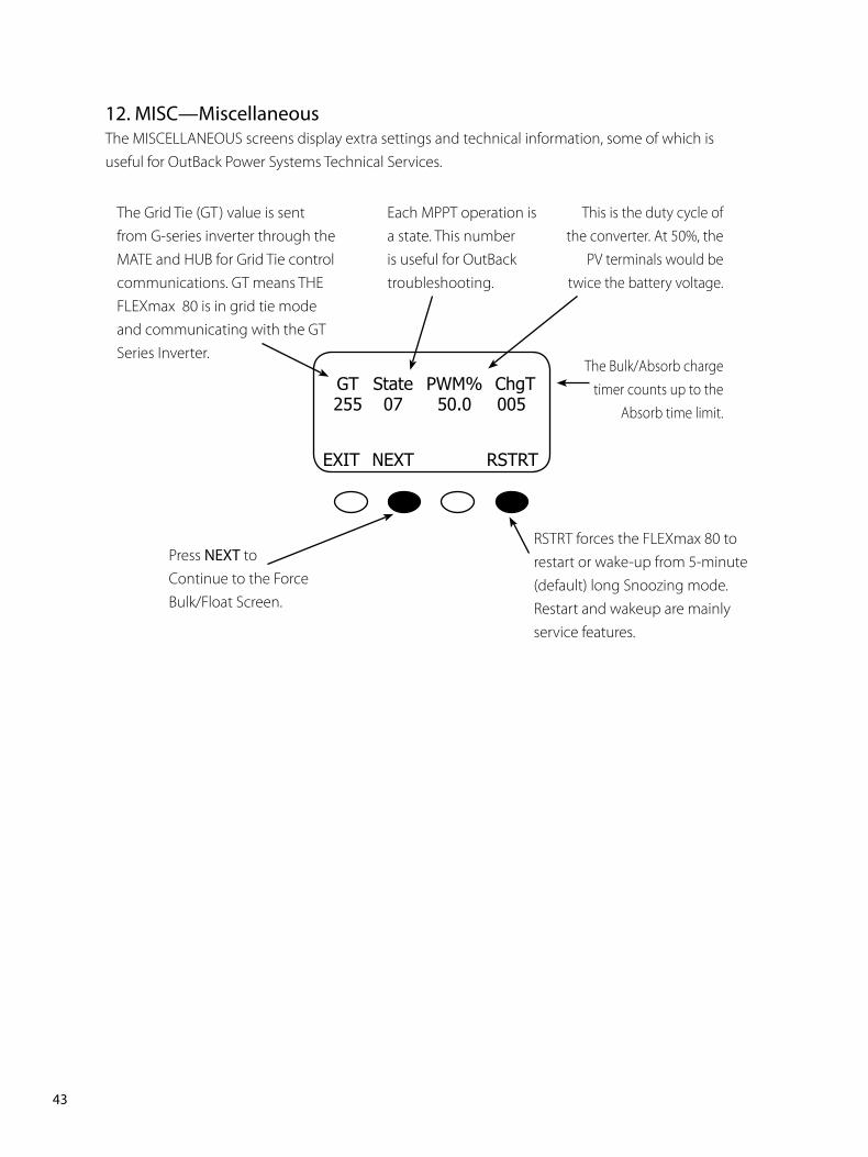
��. MISC—MiscellaneousThe MISCELLANEOUS screens display extra settings and technical information, some of which isuseful for OutBack Power Systems Technical Services.
The Grid Tie (GT) value is sent from G-series inverter through the MATE and HUB for Grid Tie control communications. GT means THE FLEXmax 80 is in grid tie mode and communicating with the GT Series Inverter.
Each MPPT operation is a state. This number is useful for OutBack troubleshooting.
This is the duty cycle of the converter. At 50%, the
PV terminals would be twice the battery voltage.
The Bulk/Absorb charge timer counts up to the
Absorb time limit.
Press NEXT to Continue to the Force Bulk/Float Screen.
RSTRT forces the FLEXmax 80 to restart or wake-up from 5-minute (default) long Snoozing mode. Restart and wakeup are mainly service features.
GT State PWM%ChgT 255 07 50.0 005
EXITNEXT RSTRT
��PB
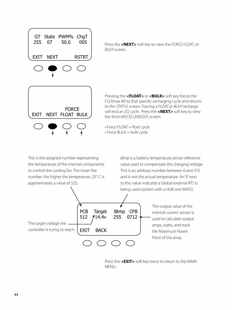
GT State PWM%ChgT 255 07 50.0 005
EXITNEXTRSTRT
Press the <NEXT> soft key to view the FORCE FLOAT, or BULK screen.
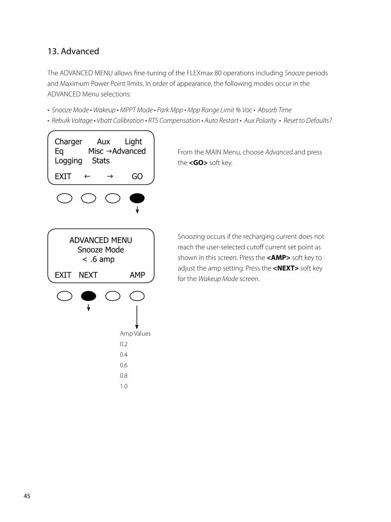
Pressing the <FLOAT> or <BULK> soft key forces the FLEXmax 80 to that specific recharging cycle and returns to the STATUS screen. Forcing a FLOAT or BULK recharge will end an EQ cycle. Press the <NEXT>soft key to view the third MISCELLANEOUS screen.
• Force FLOAT = float cycle• Force BULK = bulk cycle
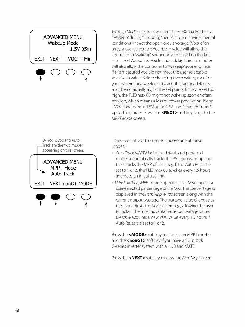
Press the <EXIT> soft key twice to return to the MAIN MENU.
FORCEEXITNEXTFLOATBULK
PCBTargetBtmpCFB51214.4v2550712
EXITBACK
This is the assigned number representing the temperature of the internal components to control the cooling fan. The lower the number, the higher the temperature. 25° C is approximately a value of 525.
Btmp is a battery temperature sensor reference value used to compensate the charging voltage. This is an arbitrary number between 0 and 255 and is not the actual temperature. An ‘X’ next to this value indicates a Global external RTS is being used (system with a HUB and MATE).
The output value of the internal current sensor is used to calculate output amps, watts, and track the Maximum Power Point of the array.
The target voltage the controller is trying to reach.
��PB
��. Advanced
The ADVANCED MENU allows fine-tuning of the FLEXmax 80 operations including Snooze periods and Maximum Power Point limits. In order of appearance, the following modes occur in the ADVANCED Menu selections:
• Snooze Mode • Wakeup • MPPT Mode • Park Mpp • Mpp Range Limit % Voc • Absorb Time • Rebulk Voltage • Vbatt Calibration • RTS Compensation • Auto Restart • Aux Polarity • Reset to Defaults?
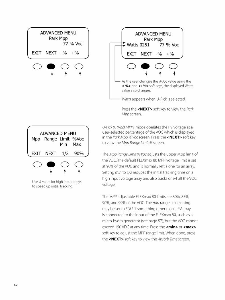
From the MAIN Menu, choose Advanced and press the <GO> soft key.
Snoozing occurs if the recharging current does not reach the user-selected cutoff current set point as shown in this screen. Press the <AMP> soft key to adjust the amp setting. Press the <NEXT>soft key for the Wakeup Mode screen.
ChargerAuxLightEqMiscgAdvancedLoggingStats
EXITfgGO
ADVANCEDMENUSnoozeMode
<.6amp
EXITNEXTAMP
Amp Values
0.2
0.4
0.6
0.8
1.0
��PB
Wakeup Mode selects how often the FLEXmax 80 does a “Wakeup” during “Snoozing” periods. Since environmental conditions impact the open circuit voltage (Voc) of an array, a user selectable Voc rise in value will allow the controller to “wakeup” sooner or later based on the last measured Voc value. A selectable delay time in minutes will also allow the controller to “Wakeup” sooner or later if the measured Voc did not meet the user selectable Voc rise in value. Before changing these values, monitor your system for a week or so using the factory defaults and then gradually adjust the set points. If they’re set too high, the FLEXmax 80 might not wake up soon or often enough, which means a loss of power production. Note: +VOC ranges from 1.5V up to 9.5V. +MIN ranges from 5 up to 15 minutes. Press the <NEXT>soft key to go to the MPPT Mode screen.
This screen allows the user to choose one of these modes:• Auto Track MPPT Mode (the default and preferred
mode) automatically tracks the PV upon wakeup and then tracks the MPP of the array. If the Auto Restart is set to 1 or 2, the FLEXmax 80 awakes every 1.5 hours and does an initial tracking.
• U-Pick % (Voc) MPPT mode operates the PV voltage at a user-selected percentage of the Voc. This percentage is displayed in the Park Mpp % Voc screen along with the current output wattage. The wattage value changes as the user adjusts the Voc percentage, allowing the user to lock-in the most advantageous percentage value.
U-Pick % acquires a new VOC value every 1.5 hours if Auto Restart is set to 1 or 2.
Press the<MODE> soft key to choose an MPPT mode and the <nonGT> soft key if you have an OutBack G-series inverter system with a HUB and MATE.
Press the <NEXT> soft key to view the Park Mpp screen.
ADVANCEDMENUWakeupMode
1.5V05m
EXITNEXT+VOC+Min
ADVANCEDMENUMPPTMode
AutoTrack
EXITNEXTnonGTMODE
U-Pick %Voc and Auto Track are the two modes appearing on this screen.
��PB
U-Pick % (Voc) MPPT mode operates the PV voltage at a user-selected percentage of the VOC which is displayed in the Park Mpp % Voc screen. Press the <NEXT> soft key to view the Mpp Range Limit % screen.
The Mpp Range Limit % Voc adjusts the upper Mpp limit of the VOC. The default FLEXmax 80 MPP voltage limit is set at 90% of the VOC and is normally left alone for an array. Setting min to 1/2 reduces the initial tracking time on a high input voltage array and also tracks one-half the VOC voltage.
The MPP adjustable FLEXmax 80 limits are 80%, 85%, 90%, and 99% of the VOC. The min range limit setting may be set to FULL if something other than a PV array is connected to the input of the FLEXmax 80, such as a micro-hydro generator (see page 57), but the VOC cannot exceed 150 VDC at any time. Press the <min>or <max> soft key to adjust the MPP range limit. When done, press the <NEXT> soft key to view the Absorb Time screen.
Use ½ value for high input arrays to speed up initial tracking.
ADVANCEDMENUMppRangeLimit%VocMinMax
EXITNEXT1/290%
ADVANCEDMENUParkMpp
Watts025177%Voc
EXITNEXT-%+%
As the user changes the %Voc value using the<-%> and <+%> soft keys, the displayed Watts value also changes.
ADVANCEDMENUParkMpp
77%Voc
EXITNEXT-%+%
Watts appears when U-Pick is selected.
Press the <NEXT> soft key to view the Park Mpp screen.
�8PB
ADVANCEDMENU AbsorbTimeLimits01.0hours
EXITNEXT-+
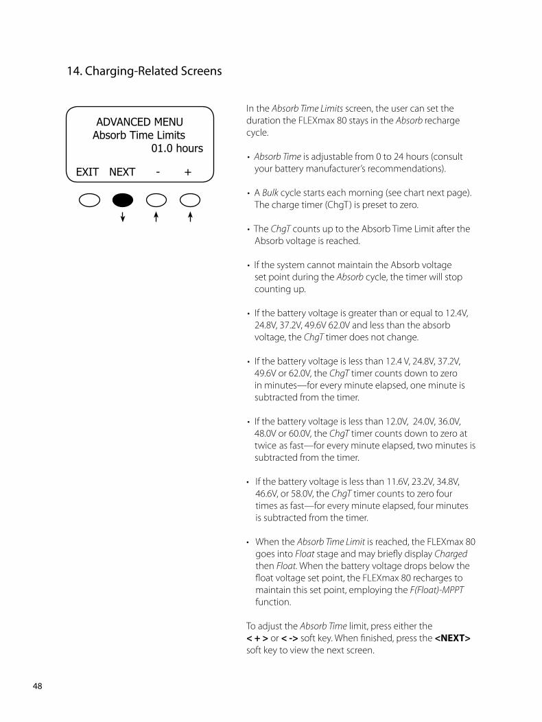
In the Absorb Time Limits screen, the user can set the duration the FLEXmax 80 stays in the Absorb recharge cycle.
• Absorb Time is adjustable from 0 to 24 hours (consult your battery manufacturer’s recommendations).
• A Bulk cycle starts each morning (see chart next page). The charge timer (ChgT) is preset to zero.
• The ChgT counts up to the Absorb Time Limit after the Absorb voltage is reached.
• If the system cannot maintain the Absorb voltage set point during the Absorb cycle, the timer will stop counting up.
• If the battery voltage is greater than or equal to 12.4V,
24.8V, 37.2V, 49.6V 62.0V and less than the absorb voltage, the ChgT timer does not change.
• If the battery voltage is less than 12.4 V, 24.8V, 37.2V, 49.6V or 62.0V, the ChgT timer counts down to zero in minutes—for every minute elapsed, one minute is subtracted from the timer.
• If the battery voltage is less than 12.0V, 24.0V, 36.0V, 48.0V or 60.0V, the ChgT timer counts down to zero at twice as fast—for every minute elapsed, two minutes is subtracted from the timer.
• If the battery voltage is less than 11.6V, 23.2V, 34.8V, 46.6V, or 58.0V, the ChgT timer counts to zero four times as fast—for every minute elapsed, four minutes is subtracted from the timer.
• When the Absorb Time Limit is reached, the FLEXmax 80 goes into Float stage and may briefly display Charged then Float. When the battery voltage drops below the float voltage set point, the FLEXmax 80 recharges to maintain this set point, employing the F(Float)-MPPT function.
To adjust the Absorb Time limit, press either the <+> or <-> soft key. When finished, press the <NEXT> soft key to view the next screen.
��. Charging-Related Screens
��PB
ADVANCEDMENUAbsorbEndAmps
00A
EXITNEXT-+
ADVANCEDMENU RebulkVoltage12.6V
EXITNEXT-+
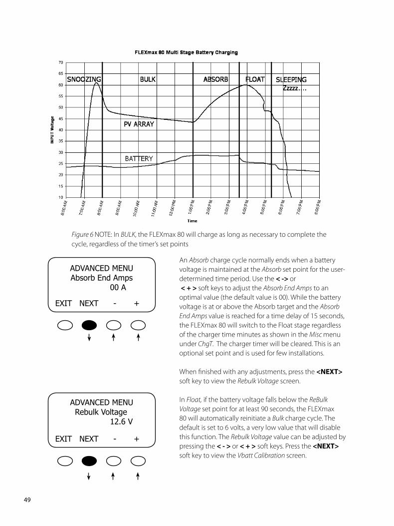
An Absorb charge cycle normally ends when a battery voltage is maintained at the Absorb set point for the user-determined time period. Use the <->or<+>soft keys to adjust the Absorb End Amps to an optimal value (the default value is 00). While the battery voltage is at or above the Absorb target and the Absorb End Amps value is reached for a time delay of 15 seconds, the FLEXmax 80 will switch to the Float stage regardless of the charger time minutes as shown in the Misc menu under ChgT. The charger timer will be cleared. This is an optional set point and is used for few installations.
When finished with any adjustments, press the <NEXT> soft key to view the Rebulk Voltage screen.
In Float, if the battery voltage falls below the ReBulk Voltage set point for at least 90 seconds, the FLEXmax 80 will automatically reinitiate a Bulk charge cycle. The default is set to 6 volts, a very low value that will disable this function. The Rebulk Voltage value can be adjusted by pressing the <->or <+> soft keys. Press the <NEXT> soft key to view the Vbatt Calibration screen.
Figure 6 NOTE: In BULK, the FLEXmax 80 will charge as long as necessary to complete the cycle, regardless of the timer’s set points
�0PB
ADVANCEDMENU RTSCompensationA14.1VF13.8V
EXITNEXTWIDE
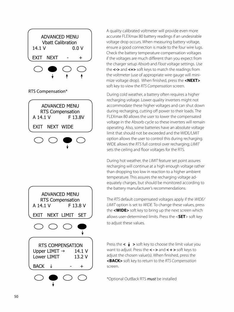
During cold weather, a battery often requires a higher recharging voltage. Lower quality inverters might not accommodate these higher voltages and can shut down during recharging, cutting off power to their loads. The FLEXmax 80 allows the user to lower the compensated voltage in the Absorb cycle so these inverters will remain operating. Also, some batteries have an absolute voltage limit that should not be exceeded and the WIDE/LMIT option allows the user to control this during recharging. WIDE allows the RTS full control over recharging; LIMIT sets the ceiling and floor voltages for the RTS.
During hot weather, the LIMIT feature set point assures recharging will continue at a high enough voltage rather than dropping too low in reaction to a higher ambient temperature. This assures the recharging voltage ad-equately charges, but should be monitored according to the battery manufacturer’s recommendations.
The RTS default compensated voltages apply if the WIDE/LIMIT option is set to WIDE. To change these values, press the <WIDE>soft key to bring up the next screen which allows user-determined limits. Press the <SET> soft key to adjust these values.
ADVANCEDMENU VbattCalibration14.1V0.0V
EXITNEXT-+
A quality calibrated voltmeter will provide even more accurate FLEXmax 80 battery readings if an undesirable voltage drop occurs. When measuring battery voltage, ensure a good connection is made to the four wire lugs. Check the battery temperature compensation voltages if the voltages are much different than you expect from the charger setup Absorb and Float voltage settings. Use the <->and <+>soft keys to match the readings from the voltmeter (use of appropriate wire gauge will mini-mize voltage drop). When finished, press the <NEXT> soft key to view the RTS Compensation screen.
ADVANCEDMENU RTSCompensationA14.1VF13.8V
EXITNEXTLIMITSET
RTS Compensation*
RTSCOMPENSATIONUpperLIMITg14.1VLowerLIMIT13.2V
BACK - +
Press the <> soft key to choose the limit value you want to adjust. Press the <-> and<+>soft keys to adjust the chosen value(s). When finished, press the <BACK> soft key to return to the RTS Compensation screen.
*Optional OutBack RTS must be installed
��PB
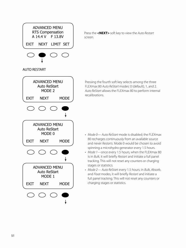
Press the <NEXT>soft key to view the Auto Restart screen.
Pressing the fourth soft key selects among the three FLEXmax 80 Auto ReStart modes: 0 (default), 1, and 2. Auto ReStart allows the FLEXmax 80 to perform internal recalibrations.
• Mode 0— Auto ReStart mode is disabled; the FLEXmax 80 recharges continuously from an available source and never Restarts. Mode 0 would be chosen to avoid spinning a microhydro generator every 1.5 hours.
• Mode 1—once every 1.5 hours, when the FLEXmax 80 is in Bulk, it will briefly Restart and initiate a full panel tracking. This will not reset any counters or charging stages or statistics.
• Mode 2— Auto ReStart every 1.5 hours; in Bulk, Absorb, and Float modes, it will briefly Restart and initiate a full panel tracking. This will not reset any counters or charging stages or statistics.
ADVANCEDMENURTSCompensationA14.4VF13.8V
EXITNEXTLIMITSET
AUTO RESTART
ADVANCEDMENUAutoReStart
MODE2
EXITNEXTMODE
ADVANCEDMENUAutoReStart
MODE0
EXITNEXTMODE
ADVANCEDMENUAutoReStart
MODE1
EXITNEXTMODE
��PB
ADVANCEDMENUAutoReStart
MODE2
EXITNEXTMODE
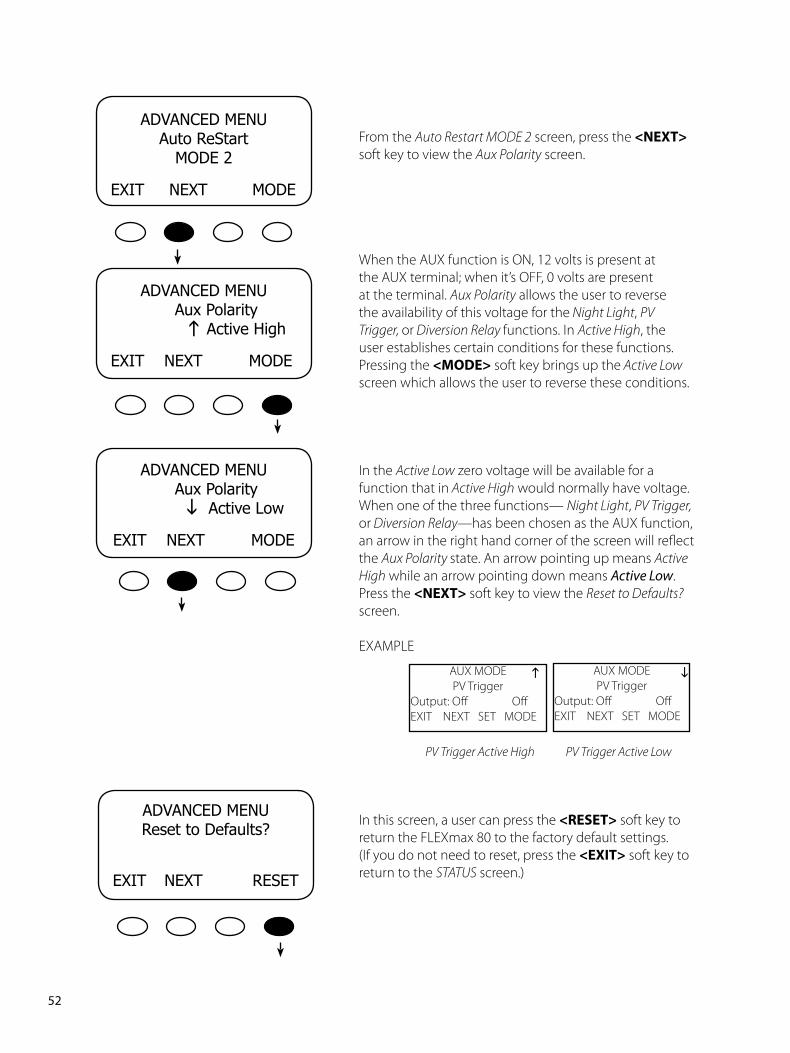
From the Auto Restart MODE 2 screen, press the <NEXT> soft key to view the Aux Polarity screen.
When the AUX function is ON, 12 volts is present at the AUX terminal; when it’s OFF, 0 volts are present at the terminal. Aux Polarity allows the user to reverse the availability of this voltage for the Night Light, PV Trigger, or Diversion Relay functions. In Active High, the user establishes certain conditions for these functions. Pressing the <MODE> soft key brings up the Active Low screen which allows the user to reverse these conditions.
In the Active Low zero voltage will be available for a function that in Active High would normally have voltage. When one of the three functions— Night Light, PV Trigger, or Diversion Relay—has been chosen as the AUX function, an arrow in the right hand corner of the screen will reflect the Aux Polarity state. An arrow pointing up means Active High while an arrow pointing down means Active Low. Press the <NEXT> soft key to view the Reset to Defaults? screen.
EXAMPLE
PV Trigger Active High PV Trigger Active Low
In this screen, a user can press the <RESET> soft key to return the FLEXmax 80 to the factory default settings. (If you do not need to reset, press the <EXIT> soft key to return to the STATUS screen.)
ADVANCEDMENUAuxPolarity
ActiveLow
EXITNEXTMODE
ADVANCEDMENUAuxPolarity
ActiveHigh
EXITNEXTMODE
ADVANCEDMENUResettoDefaults?
EXIT NEXTRESET
g
g
AUX MODE PV Trigger
Output: Off OffEXIT NEXT SET MODE
g AUX MODE PV Trigger
Output: Off OffEXIT NEXT SET MODE
g
��PB
ADVANCEDMENUResettoDefaults?
EXIT NEXTRESET
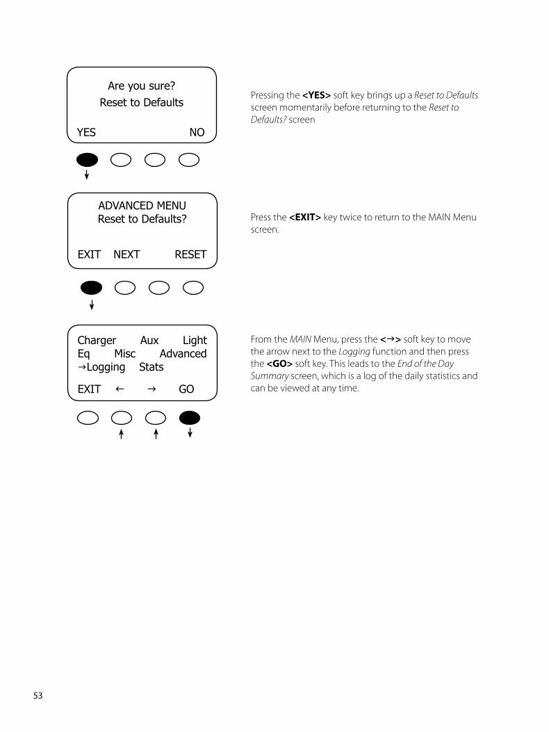
Pressing the <YES> soft key brings up a Reset to Defaults screen momentarily before returning to the Reset to Defaults? screen
Press the <EXIT> key twice to return to the MAIN Menu screen.
From the MAIN Menu, press the <g> soft key to move the arrow next to the Logging function and then press the <GO> soft key. This leads to the End of the Day Summary screen, which is a log of the daily statistics and can be viewed at any time.
ChargerAuxLightEqMiscAdvancedgLoggingStats
EXITfgGO
Areyousure?ResettoDefaults
YESNO
��PB
CLEARLOG
BACKTOTLDAILY
Areyousure?
NOYES
Today0000Ah00.0KWH011Vp00.0Ap0.00kWpMAX14.7VABS01:00MIN14.6VFLT00:00
Today0000Ah00.0KWH011Vp00.0Ap0.00kWpMAX14.7VABS01:00MIN14.6VFLT00:00
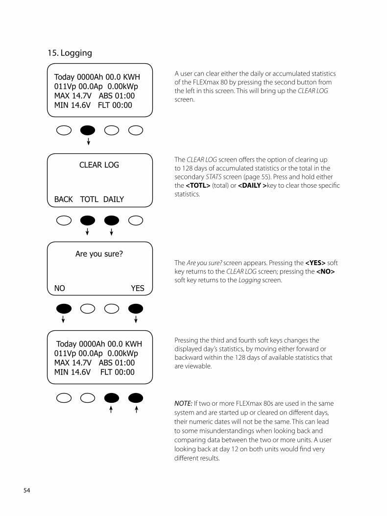
A user can clear either the daily or accumulated statistics of the FLEXmax 80 by pressing the second button from the left in this screen. This will bring up the CLEAR LOG screen.
The CLEAR LOG screen offers the option of clearing up to 128 days of accumulated statistics or the total in the secondary STATS screen (page 55). Press and hold either the <TOTL> (total) or <DAILY>key to clear those specific statistics.
The Are you sure? screen appears. Pressing the <YES> soft key returns to the CLEAR LOG screen; pressing the <NO> soft key returns to the Logging screen.
Pressing the third and fourth soft keys changes the displayed day’s statistics, by moving either forward or backward within the 128 days of available statistics that are viewable.
NOTE: If two or more FLEXmax 80s are used in the same system and are started up or cleared on different days, their numeric dates will not be the same. This can lead to some misunderstandings when looking back and comparing data between the two or more units. A user looking back at day 12 on both units would find very different results.
��. Logging
��PB
ChargerAuxLightEqMiscAdvancedLogginggStats
EXITfg GO
From the MAIN Menu, press the <g>soft key to move the arrow next to the Stats function and then press the<GO> soft key
The STATS screen displays additional voltage and time information.
Press the <NEXT> soft key to view the second STATS screen
The highest Voc seen by the FLEXmax 80
Maximum battery voltage seen by the FLEXmax 80
In a standalone FLEXmax 80—one that is not connected to a MATE—Sunrise shows how long ago the FLEXmax 80 woke up for the first time each day and when the daily and total logged values were updated and cleared from the STATUS screen. If the FLEXmax 80 is connected to a MATE, the logging occurs at midinght.
MaxBatVocMaxVoc14.9036.6133.0MaxWatt0000Sunrise
EXITNEXT01:30:33
Max Watt seen by the FLEXmax 80
Daily high VOC value
��. Stats
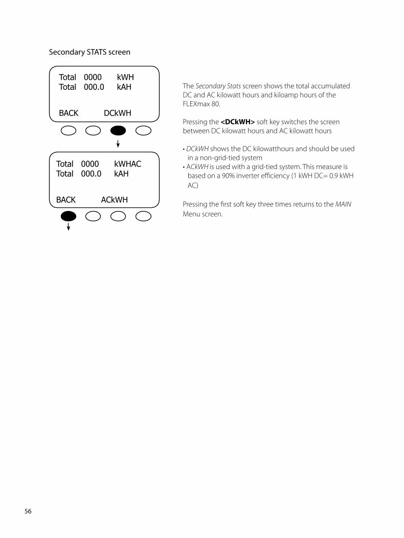
��PB
Total0000kWHTotal000.0kAH
BACKDCkWH
The Secondary Stats screen shows the total accumulated DC and AC kilowatt hours and kiloamp hours of the FLEXmax 80.
Pressing the <DCkWH> soft key switches the screen between DC kilowatt hours and AC kilowatt hours
• DCkWH shows the DC kilowatthours and should be used in a non-grid-tied system
• ACkWH is used with a grid-tied system. This measure is based on a 90% inverter efficiency (1 kWH DC= 0.9 kWH AC)
Pressing the first soft key three times returns to the MAIN Menu screen.
Total0000kWHACTotal000.0kAH
BACKACkWH
Secondary STATS screen
��PB
��. Micro-Hydro and Fuel Cell Applications
The FLEXmax 80 is designed to work with solar arrays. Although it will work with micro-hydro turbines
and fuel cell, OutBack Power Systems can only offer limited technical support for these applications
because there is too much variance in micro-hydro and fuel cell generator specifications. When
used for micro-hydro or fuel cell applications, the FLEXmax 80 warranty will be honored only if the
manufacturer and turbine model have been approved by OutBack Power Systems. Please check with
one of the following manufacturers or OutBack Power Systems before employing the FLEXmax 80 with
these applications:
• Harris Hydroelectric (831) 425-7652 www.harrishydro.com
• Alternative Power & Machine (541) 476-8916 www.apmhydro.com
• Energy System & Design (506) 433-3151 www.microhydropower.com
TheFLEXmax80isnotcompatiblewithwindturbineapplications and OutBack cannot
warranty its use in these applications.
MICRO-HYDRO AND FUEL CELL SYSTEMS PERFORMANCE OPTIMIZATION Micro-hydro and fuel cell systems are different than PV systems, whose VOC output is more subject to
change due to weather and time of day. A PV system normally finds its Maximum Power Point voltage
between 50-90% of its VOC. A micro-hydro or fuel cell system’s MPP voltage can be outside of this
range.
The FLEXmax 80 allows a user to experiment and find more appropriate set points to best capture
the MPP voltage using U-Pick mode. Otherwise, Auto Track begins tracking the VOC and works its way
down until the optimum percentage of input voltage yields the MPP voltage. If U-Pick % Voc is chosen,
the MPP is calculated by whatever value is found in Park Mpp, even if it’s not the optimal value for
determining the MPP voltage. For this reason, OutBack normally suggests leaving the system in Auto
Sweep mode.
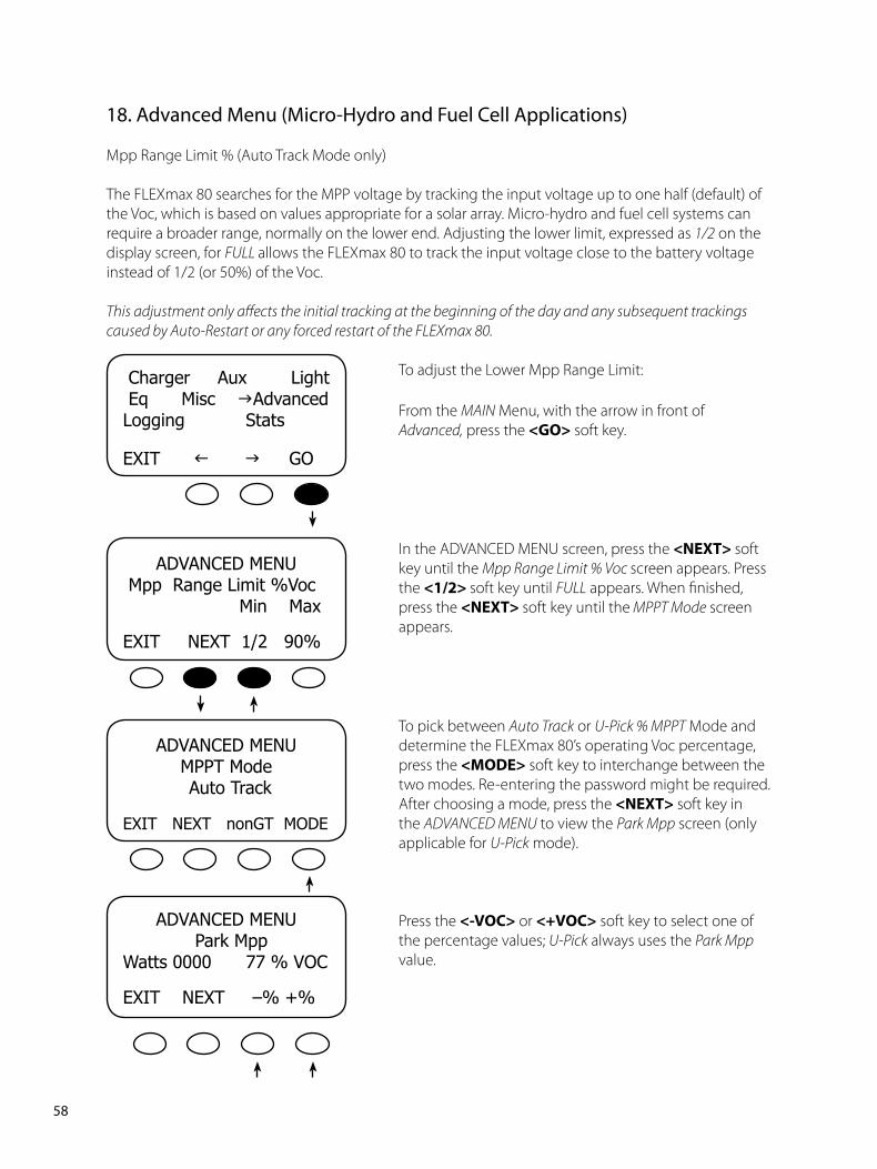
�8PB
�8. Advanced Menu (Micro-Hydro and Fuel Cell Applications)
Mpp Range Limit % (Auto Track Mode only)
The FLEXmax 80 searches for the MPP voltage by tracking the input voltage up to one half (default) of the Voc, which is based on values appropriate for a solar array. Micro-hydro and fuel cell systems can require a broader range, normally on the lower end. Adjusting the lower limit, expressed as 1/2 on the display screen, for FULL allows the FLEXmax 80 to track the input voltage close to the battery voltage instead of 1/2 (or 50%) of the Voc.
This adjustment only affects the initial tracking at the beginning of the day and any subsequent trackings caused by Auto-Restart or any forced restart of the FLEXmax 80.
To adjust the Lower Mpp Range Limit:
From the MAIN Menu, with the arrow in front of Advanced, press the <GO> soft key.
In the ADVANCED MENU screen, press the <NEXT>soft key until the Mpp Range Limit % Voc screen appears. Press the <1/2>soft key until FULL appears. When finished, press the <NEXT>soft key until the MPPT Mode screen appears.
To pick between Auto Track or U-Pick % MPPT Mode and determine the FLEXmax 80’s operating Voc percentage, press the <MODE> soft key to interchange between the two modes. Re-entering the password might be required. After choosing a mode, press the <NEXT> soft key in the ADVANCED MENU to view the Park Mpp screen (only applicable for U-Pick mode).
Press the <-VOC> or <+VOC> soft key to select one of the percentage values; U-Pick always uses the Park Mpp value.
ChargerAuxLightEqMiscgAdvancedLoggingStats
EXITfgGO
ADVANCEDMENUMppRangeLimit%VocMinMax
EXITNEXT1/290%
ADVANCEDMENUMPPTMode
AutoTrack
EXITNEXTnonGTMODE
ADVANCEDMENUParkMppWatts0000 77%VOC
EXITNEXT–%+%
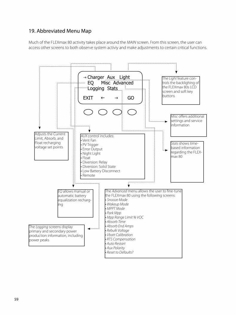
��PB
g ChargerAuxLightEQMiscAdvancedLoggingStats
EXITfg GO
Adjusts the Current Limit, Absorb, and Float recharging voltage set points
AUX control includes:• Vent Fan• PV Trigger• Error Output• Night Light• Float• Diversion: Relay• Diversion: Solid State• Low Battery Disconnect• Remote
The Light feature con-trols the backlighing of the FLEXmax 80s LCD screen and soft key buttons
EQ allows manual or automatic battery equalization recharg-ing
Misc offers additional settings and service information
The Advanced menu allows the user to fine-tune the FLEXmax 80 using the following screens:• Snooze Mode• Wakeup Mode• MPPT Mode• Park Mpp• Mpp Range Limit % VOC• Absorb Time• Absorb End Amps• Rebulk Voltage• Vbatt Calibration• RTS Compensation• Auto Restart• Aux Polarity• Reset to Defaults?
The Logging screens display primary and secondary power production information, including power peaks
Stats shows time-based information regarding the FLEX-max 80
��. Abbreviated Menu Map
Much of the FLEXmax 80 activity takes place around the MAIN screen. From this screen, the user can access other screens to both observe system activiy and make adjustments to certain critical functions.
�0PB
�0. Application Notes
OutBack Power System GTFX/GVFX Grid-tie settingsIn a GFX/GVFX Series Inverter/Charger, FLEXmax 80, HUB, and MATE installation set the FLEXmax 80 to GT mode in the ADVANCED MENU. GT mode allows the GFX/GVFX to manage the FLEXmax 80 float setting ensuring the FLEXmax 80 is always keeping the battery above the sell voltage of the GFX/GVFX.
Grid-tie applications (non-OutBack inverter/chargers)When selling electricity back to the grid, keep the inverter Sell/Float voltage below the FLEXmax 80 float voltage. Appropriate values: 0.5 Volts difference for 24V battery system or 1.0 volt difference for 48V battery systems.
Positive grounded systemsTelcom applications frequently require a positive grounded system. The FLEXmax 80 switches the POSITIVE PV and battery leads. Keep these separate. If code allows, ground ONLY the battery positive lead in this case. Do not connect the FLEXmax 80’s battery plus to the PV plus input while the FLEXmax 80 is running. The OutBack HUB cannot be used in a positive grounded system.
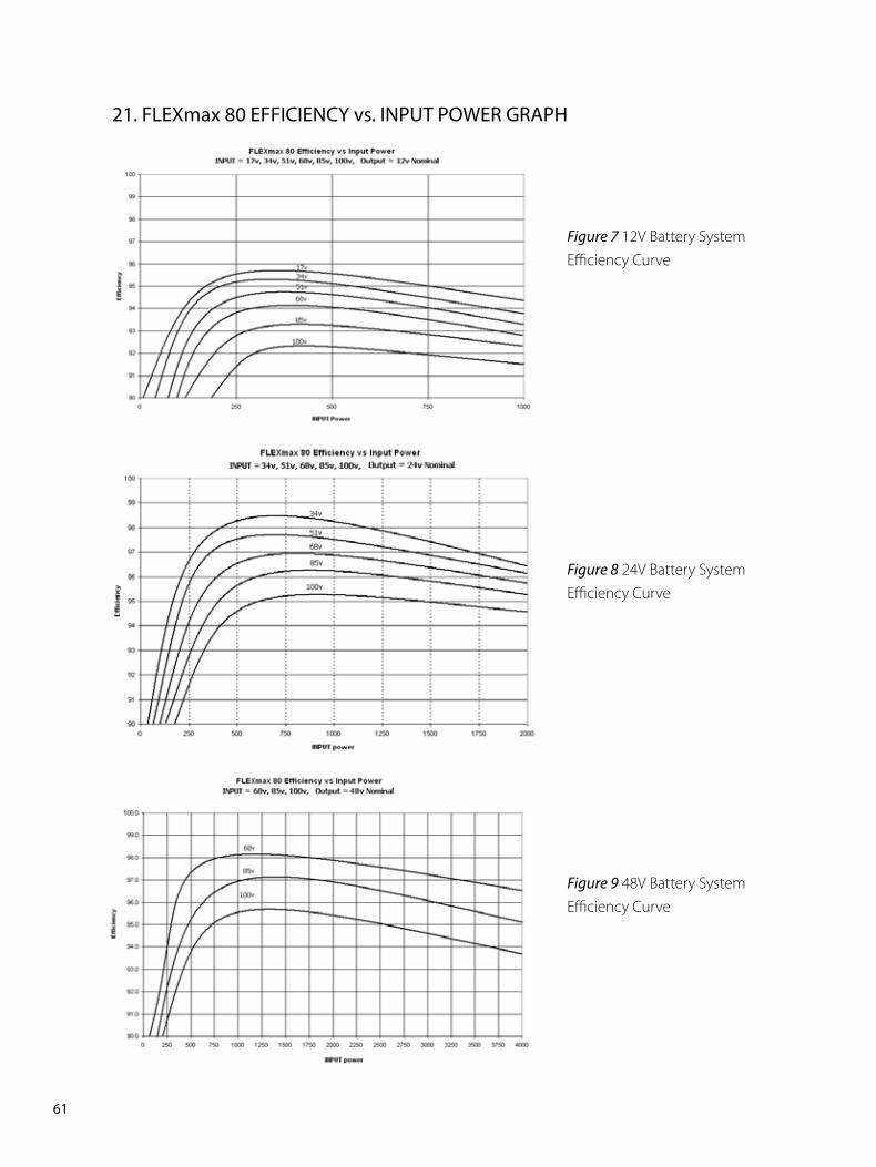
��PB
��. FLEXmax 80 EFFICIENCY vs. INPUT POWER GRAPH
Figure 7 12V Battery System Efficiency Curve
Figure 8 24V Battery System Efficiency Curve
Figure 9 48V Battery System Efficiency Curve
��PB
��. Understanding the Various Operational Modes
The FLEXmax 80 modes of operation will change occasionally during the day based on the PV array output and the battery system state of charge. The FLEXmax 80 operating modes are displayed at the bottom right hand corner of the STATUS screen.
Absorbing The FLEXmax 80 is in the Absorb (constant voltage) charge stage, regulating the battery voltage at the Absorb voltage set point (modified by battery temperature compensation if installed). During this cycle, the ChgT counter in the Misc menu is counting up towards the user defined Absorb Time Limit. If the system cannot regulate the battery voltage at the Absorb voltage set point, then the FLEXmax 80 reverts back to the Bulk charge stage, display MPPT Bulk, and the ChgT counter may start counting down towards zero minutes or until the Absorb target is met. See page 48 for more information.
AutoStart (Auto Re-Start) Mode 1—Once every 1.5 hours in Bulk cycle and in Mode 2, once every 1.5 hours in the Bulk, Absorb and Float recharging modes, the FLEXmax 80 will start over from sleeping and re-track (full track) and re-calibrate the current sensor. Mode 0 is disabled completely. (See Stats menu). Note: If enabled, AutoStart also occurs during the MPPT EQ cycle.
BatTmpErr The battery temperature sensor is shorted or damaged. The charging voltage will not be temperature compensated and the cooling fan will continuously operate.
BatTooHot The battery temperature sensor has detected a battery temperature of over 50°C. The FLEXmax 80 will stop charging the battery and wait for the battery to cool below 50°C.
Charged There is an external DC source other than solar keeping the battery above the Float voltage set point-- the FLEXmax 80 will stop charging. The display may also appear when the charge cycle is transitioning from Absorbing (upper target voltage) to Floating (lower target voltage).
EQ 0:00 This is the time elapsed in hours and minutes since the Equalization voltage set point was met.If the EQ voltage set point is not maintained, the controller will revert back – the EQ timer will pause until the batteries are regulated at the EQ voltage set point again. The paused time can be viewed in the Stats menu.
EQ Done Once the set EQ time (between 1 and 7 hours) has successfully completed, EQ Done will be displayed either until a button is pressed, or the next morning’s wakeup. The FLEXmax 80 will transition to Float cycle at the end of the completed EQ cycle.
EX-Absorb There is an external DC source other than solar keeping the battery above the Absorb voltage set point. The FLEXmax 80 will stop charging.
Floating The FLEXmax 80 is in the Float (constant voltage) charge stage and is regulating the battery at the Float voltage set point (modified by battery temperature compensation, if installed). If the system cannot maintain the Float voltage set point, (e.g. AC and/or DC loads are on), the FLEXmax 80 will employ the MPPT function, display MPPT Float, and try its best to regulate the batteries to the Float voltage set point.
��PB
GT Mode In a system with an OutBack FX Grid-Tie Series Inverter(s), HUB and MATE, the FLEXmax 80 will display GT Mode if and only if the inverter is in Sell mode and the FLEXmax 80 is in Bulk (MPPT BULK) or Float (MPPT FLOAT) cycle. This is also a good indicator for establishing proper Grid-Tie mode communication between the FX G-Series Inverter(s) and FLEXmax 80. GT must be selected in the MPPT Mode Advanced menu in order to be viewed.
High VOC This indicates the PV array’s open circuit voltage is too high for the controller to safely operate. This should only occur with systems using 72 VDC nominal PV arrays in very cold temperatures (below 5° F / -15° C). The controller will automatically restart operation once the PV array’s open circuit voltage falls to a safe level (145 VDC or lower). The amount of time required before starting operation is dependent on the module type, ambient temperature, and the amount of sunlight directly on the PV array. Normally, the controller starts in the morning within a few minutes of the PV array being in direct sunlight.
Low Light / Snoozing During the initial tracking (see Wakeup and Tracking), if it is determined tobe too late (or too early) in the day, the FLEXmax 80 will display Low Light for a few seconds and then display Snoozing for 5 minutes (default). This reduces energy usage and unnecessary powering of the FLEXmax 80. This message is also displayed in extremely cloudy weather.
MPPT Bulk The FLEXmax 80 is in Maximum Power Point Tracking mode trying to regulate the battery voltage towards the Absorb voltage set point. If the FLEXmax 80 transitioned from Absorbing to MPPT Bulk, the Charge Timer (ChgT) counter may start counting down towards zero minutes or until the Absorb target is met. See page 47 for more information.
MPPT Float The FLEXmax 80 is in Maximum Power Point Tracking mode trying to regulate the battery voltage towards the Float voltage set point. Note: Charge Timer (ChgT) is inactive in the Float state.
New VOC The FLEXmax 80 is acquiring a new open circuit panel voltage (VOC).
OvrCurrent If more than 6A flowing from the battery or more than 100A flowing to the battery. To reinitiate power production, press ”RSTRT” in the “Misc” menu.
Over Temp (Very rare) Either the FLEXmax 80 is too hot or its internal temperature sensor is shorted. If this message appears, carefully check if the FLEXmax 80’s heat sink is extremely hot. The heat generated by the FLEXmax 80, and therefore its losses, is proportional to input voltage times output current. To help control its operating temperature, avoid installing the FLEXmax 80 in direct sunlight
Re-Cal There are certain abnormal conditions that can confuse the current measuring method in the FLEXmax 80. When and if one happens, the FLEXmax 80 will temporarily stop and re-calibrate. This may happen because of negative current, i.e., current flowing from the battery, or a tripped PV breaker. A new
VOC is also acquired during a Re-Cal.
MPPT EQ The equalization cycle has started and the FLEXmax 80 is trying to regulate at the Equalization voltage set point. EQ is not battery temperature compensated. During an equalization cycle, EQ 0:00 will be displayed along with the EQ time in hours and minutes. The AC/DC loads should be turned off/minimized and the battery charged so the FLEXmax 80 can quickly reach the EQ voltage set point. Otherwise, the FLEXmax 80 may not reach or maintain the EQ cycle.
��PB
Sleeping The PV voltage is two volts less than the battery voltage. This may also appear during the day
when the FLEXmax 80 is transitioning between certain states, or due to other conditions.
SysError (Very rare) System Error indicates an internal non-volatile memory error. The unit will stop
operating when this message is displayed. Call the factory if you see this message (360-435-6030).
Tracking In Auto-Sweep MPPT mode, the FLEXmax 80 is doing an initial tracking of the panel voltage from
VOC towards battery voltage after wakeup. This display also appears when the controller transitions from a
target set point (Absorbing/ Floating/EQ 0:00) to the MPPT state (MPPT Bulk/ MPPT Float/ MPPT EQ).
Unloaded The battery terminals abruptly unload. Unloaded is also displayed if the battery breaker trips
while MPPTing or the battery voltage is set too low.
Wakeup As the PV open circuit voltage (VOC) rises above the battery system voltage by two volts, the
FLEXmax 80 prepares to deliver power to the batteries. During this period, the FLEXmax 80 is calculating the
pulse width modulation (PWM) duty cycles, turning on power supply voltages in the proper sequences, and
making internal calibrations. At wakeup, the FLEXmax 80 closes its relays and then starts tracking the input
voltage (the “initial” tracking) towards the battery voltage. At dawn and dusk this may happen many times
until there is (or is not) enough power from the PV array to keep going. Wakeup is also a time when the
FLEXmax 80 acquires a new VOC.
Zzzzz... At night (after 3 hours of continuous Sleeping) the FLEXmax 80 will display Zzzzz... until the
next wakeup. At the next wakeup, (usually the next morning), the daily statistics of a single FLEXmax 80,
(AmpHours, KWh, etc.), will accumulate into the total statistics and then the displayed daily statistics and
End of Day summary will clear. A Bulk charge will automatically initiate at the next Wakeup. A FLEXmax 80
combined with a HUB and a MATE will log at midnight.
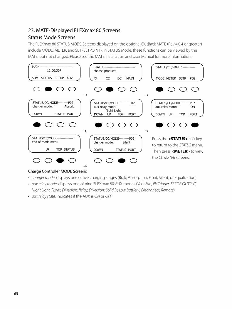
��PB
��. MATE-Displayed FLEXmax 80 ScreensStatus Mode ScreensThe FLEXmax 80 STATUS MODE Screens displayed on the optional OutBack MATE (Rev 4.0.4 or greater) include MODE, METER, and SET (SETPOINT). In STATUS Mode, these functions can be viewed by the MATE, but not changed. Please see the MATE Installation and User Manual for more information.
Charge Controller MODE Screens• charger mode: displays one of five charging stages (Bulk, Absorption, Float, Silent, or Equalization)• aux relay mode: displays one of nine FLEXmax 80 AUX modes (Vent Fan, PV Trigger, ERROR OUTPUT,
Night Light, FLoat, Diversion: Relay, Diversion: Solid St, Low Batt(ery) Disconnect, Remote)• aux relay state: indicates if the AUX is ON or OFF
Press the <STATUS> soft key to return to the STATUS menu. Then press <METER> to view the CC METER screens.
MAIN------------------------------12:00:30P
SUMSTATUSSETUPADV
STATUS---------------------------chooseproduct:
FXCCDCMAIN
STATUS/CC/PAGE1-----------
MODEMETERSETPPG2
STATUS/CC/MODE---------P02chargermode:Absorb
DOWNSTATUSPORT
STATUS/CC/MODE---------P02auxrelaymode:NightLightDOWNUPTOPPORT
STATUS/CC/MODE--------P02auxrelaystate:ON
DOWNUPTOPPORT
STATUS/CC/MODE--------------endofmodemenu
UPTOPSTATUS
STATUS/CC/MODE---------P02chargermode:Silent
DOWNSTATUSPORT
g g
g g
g
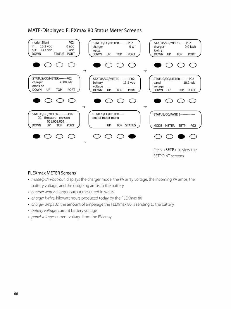
��PB
MATE-Displayed FLEXmax 80 Status Meter Screens
FLEXmax METER Screens• mode/pv/in/bat/out: displays the charger mode, the PV array voltage, the incoming PV amps, the
battery voltage, and the outgoing amps to the battery• charger watts: charger output measured in watts• charger kwhrs: kilowatt hours produced today by the FLEXmax 80• charger amps dc: the amount of amperage the FLEXmax 80 is sending to the battery• battery voltage: current battery voltage• panel voltage: current voltage from the PV array
mode:SilentP02in10.2vdc0adcout:13.4vdc0adcDOWNSTATUSPORT
STATUS/CC/METER--------P02charger0wwattsDOWNUPTOPPORT
STATUS/CC/METER-----P02charger0.0kwhkwhrsDOWNUPTOPPORT
STATUS/CC/METER-------P02charger+000adcampsdcDOWNUPTOPPORT
STATUS/CC/METER---------P02battery13.5vdcvoltageDOWNUPTOPPORT
STATUS/CC/METER--------P02panel10.2vdcvoltageDOWNUPTOPPORT
STATUS/CC/METER-----endofmetermenu
UPTOPSTATUS
STATUS/CC/PAGE1-------------
MODEMETERSETPPG2
g g
g g
g
Press <SETP> to view theSETPOINT screens
STATUS/CC/METER---------P02CC firmware revision
001.008.009DOWNUPTOPPORT
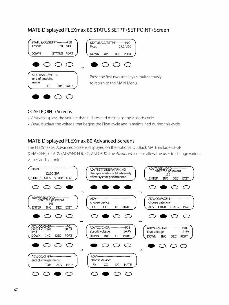
��PB
MATE-Displayed FLEXmax 80 STATUS SETPT (SET POINT) Screen
Press the first two soft keys simultaneously to return to the MAIN Menu.
CC SETP(OINT) Screens• Absorb: displays the voltage that initiates and maintains the Absorb cycle• Float: displays the voltage that begins the Float cycle and is maintained during this cycle
STATUS/CC/SETPT---------P00Absorb28.8VDC
DOWNSTATUSPORT
STATUS/CC/SETPT---------P00Float27.2VDC
DOWNUPTOPPORT
STATUS/CC/METER------endofsetpointmenuUPTOPSTATUS
g
MATE-Displayed FLEXmax 80 Advanced ScreensThe FLEXmax 80 Advanced Screens displayed on the optional OutBack MATE include CHGR (CHARGER), CCADV (ADVANCED), EQ, AND AUX. The Advanced screens allow the user to change various values and set points.
MAIN------------------------------12:00:30P
SUMSTATUSSETUPADV
ADV/SETTINGS/WARNINGchangesmadecouldadverselyeffectsystemperformance
ADV/PASSWORD-------------enterthepassword132ENTERINCDECEXIT
ADV/PASSWORD-------------enterthepassword141ENTERINCDECEXIT
ADV------------------------------choosedevice:FXCCDCMATE
ADV/CC/PAGE1----------------choosecategory:ADVCHGRCCADVPG2
ADV/CC/CHGR--------------P01outputcurrent80.0AlimitDOWNINCDECPORT
ADV/CC/CHGR--------------P01absorbvoltage14.4VDOWNINCDECPORT
g g
g g
g
ADV/CC/CHGR--------------P01float voltage 13.6VDOWNINCDECPORT
ADV/CC/CHGR------------------endofchargermenuTOPADVMAIN
gADV------------------------------choosedevice:FXCCDCMATE
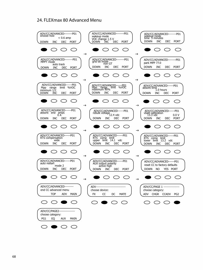
�8PB
ADV/CC/ADVANCED--------P01snoozenow<0.6ampDOWNINCDECPORT
ADV/CC/ADVANCED--------P01wakeupmodeVOCchange1.5VDOWNINCDECPORT
ADV/CC/ADVANCED--------P01wakeupmodetime5minutesDOWNINCDECPORT
ADV/CC/ADVANCED--------P01MPPTmodeautotrackDOWNINCDECPORT
ADV/CC/ADVANCED--------P01gridtiemodenonGTDOWNINCDECPORT
ADV/CC/ADVANCED--------P01parkMPP77.0DOWNINCDECPORT
ADV/CC/ADVANCED------P01Mpprangelimit%VOCminimum1/2DOWNINCDECPORT
ADV/CC/ADVANCED------P01Mpprangelimit%VOCmaximum90%DOWNINCDECPORT
g g
g g
g
ADV/CC/ADVANCED------P01absorbtime1.0hoursDOWNINCDECPORT
ADV/CC/ADVANCED------P01absorbendamps0ADOWNINCDECPORT
gADV/CC/ADVANCED------P01rebulkvoltage12.4vdcDOWNINCDECPORT
ADV/CC/ADVANCED------P01vbattcalibration13.3vdc0.0VDOWNINCDECPORT
g
ADV/CC/ADVANCED------P01RTScompensationwideDOWNINCDECPORT
gADV/CC/ADVANCED------P01RTScomplimitupperlimit14.1vdcDOWNINCDECPORT
ADV/CC/ADVANCED------P01RTScomplimitlowerlimit13.2vdcDOWNINCDECPORT
g
ADV/CC/ADVANCED------P01autorestartmode2DOWNINCDECPORT
gADV/CC/ADVANCED------P01resetCCtofactorydefaultsDOWNNOYESPORT
ADV/CC/ADVANCED---------endCCadvancedmenuTOPADVMAIN
g
ADV------------------------------choosedevice:FXCCDCMATE
g
ADV/CC/PAGE1----------------choosecategory:ADVCHGRCCADVPG2
ADV/CC/PAGE2----------------choosecategory:PG1EQAUXMAIN
��. FLEXmax 80 Advanced Menu
ADV/CC/ADVANCED------P01AUXoutputpolarityactivehighDOWNINCDECPORT

��PB
FLEXmax 80 EQ Screens
ADV/CC/AUX/MODE--------P01NightLightDOWNINCSETPORT
ADV/CC/AUX/--------------P01auxoutputOFFcontrolDOWNONOFFPORT
ADV/CC/AUX/-----------------endofmenuTOPADVMAIN
ADV/CC/EQ-----------------P01eqvoltage14.4vdcDOWNINCDECPORT
ADV/CC/EQ-----------------P01eqtime1hrsDOWNINCDECPORT
ADV/CC/EQ-----------------P01autoeqinterval0daysDOWNINCDECPORT
ADV/CC/EQ----------------------endofCCeqmenuTOPADVMAIN
g
FLEXmax 80 AUX Screens
FLEXmax 80 LOGGING Screens
Today0000Ah00.0KWH011Vp00.0Ap0.00kWpMAX14.7VABS01:00MIN14.6VFLT00:00
CLEARLOG
BACKTOTLDAILY
Areyousure?
NOYES
Today0000Ah00.0KWH011Vp00.0Ap0.00kWpMAX14.7VABS01:00MIN14.6VFLT00:00
g
g
g g
g
FLEXmax 80 STATS Screens
MaxBatVocMaxVoc14.9036.6133.0MaxWatt0000SunriseEXITNEXT01:30:33
Total0000kWHTotal000.0kAHBACKDCkWH
Total0000kWHACTotal000.0kAHBACKACkWH
g g
FLEXmax 80 Displayed Screens
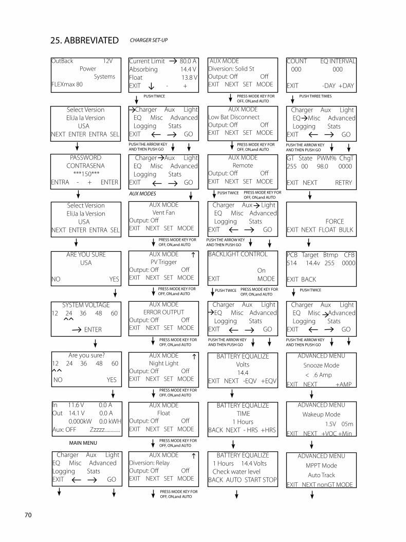
�0PB
��. ABBREVIATED CHArGEr SET-UP
Select VersionEliJa la Version
USANEXT ENTER ENTRA SEL
PASSWORDCONTRASENA
***150***ENTRA - + ENTER
Select VersionEliJa la Version
USANEXT ENTER ENTRA SEL
ARE YOU SUREUSA
NO YES
SYSTEM VOLTAGE12 24 36 48 60
ENTER
OutBack 12V Power SystemsFLEXmax 80
In 11.6 V 0.0 AOut 14.1 V 0.0 A 0.000kW 0.0 kWHAux: OFF Zzzzz.............
Charger Aux LightEQ Misc AdvancedLogging StatsEXIT GO
Charger Aux Light EQ Misc Advanced Logging StatsEXIT GO
Charger Aux Light EQ Misc Advanced Logging StatsEXIT GO
AUX MODEVent Fan
Output: OffEXIT NEXT SET MODE
AUX MODE PV Trigger
Output: Off OffEXIT NEXT SET MODE
AUX MODEERROR OUTPUT
Output: Off OffEXIT NEXT SET MODE
AUX MODENight Light
Output: Off OffEXIT NEXT SET MODE
Current Limit 80.0 AAbsorbing 14.4 VFloat 13.8 VEXIT - +
AUX MODEFloat
Output: Off OffEXIT NEXT SET MODE
AUX MODEDiversion: RelayOutput: Off OffEXIT NEXT SET MODE
AUX MODELow Bat DisconnectOutput: Off OffEXIT NEXT SET MODE
AUX MODERemote
Output: Off OffEXIT NEXT SET MODE
Charger Aux Light EQ Misc Advanced Logging StatsEXIT GO
BACKLIGHT CONTROL
OnEXIT MODE
AUX MODEDiversion: Solid StOutput: Off OffEXIT NEXT SET MODE
FORCEEXIT NEXT FLOAT BULK
PCB Target Btmp CFB514 14.4v 255 0000
EXIT BACK
Charger Aux Light EQ Misc Advanced Logging StatsEXIT GO
ADVANCED MENUSnooze Mode
< .6 AmpEXIT NEXT +AMP
ADVANCED MENUWakeup Mode
1.5V 05mEXIT NEXT +VOC +Min
ADVANCED MENUMPPT ModeAuto Track
EXIT NEXT nonGT MODE
GT State PWM% ChgT255 00 98.0 0000
EXIT NEXT RETRY
MAIN MENU
PUSH TWICE
PUSH TWICE
PUSH TWICE
Charger Aux Light EQ Misc Advanced Logging StatsEXIT GO
BATTERY EQUALIZEVolts14.4
EXIT NEXT -EQV +EQV
PUSH TWICE
PUSH THE ARROW KEY AND THEN PUSH GO
PUSH THE ARROW KEY AND THEN PUSH GO
PUSH THE ARROW KEY AND THEN PUSH GO
PUSH THE ARROW KEY AND THEN PUSH GO
PRESS MODE KEY FOR OFF, ON,and AUTO
PRESS MODE KEY FOR OFF, ON,and AUTO
PRESS MODE KEY FOR OFF, ON,and AUTO
PRESS MODE KEY FOR OFF, ON,and AUTO
PRESS MODE KEY FOR OFF, ON,and AUTO
PRESS MODE KEY FOR OFF, ON,and AUTO
PRESS MODE KEY FOR OFF, ON,and AUTO
PRESS MODE KEY FOR OFF, ON,and AUTO
PRESS MODE KEY FOR OFF, ON,and AUTO
BATTERY EQUALIZE TIME
1 HoursBACK NEXT - HRS +HRS
BATTERY EQUALIZE 1 Hours 14.4 Volts Check water levelBACK AUTO START STOP
COUNT EQ INTERVAL 000 000
EXIT -DAY +DAY
Charger Aux Light EQ Misc Advanced Logging StatsEXIT GOPUSH THE ARROW KEY AND THEN PUSH GO
PUSH THREE TIMES
AUX mODES
PRESS MODE KEY FOR OFF, ON,and AUTO
gg
g
Are you sure?12 24 36 48 60
NO YES
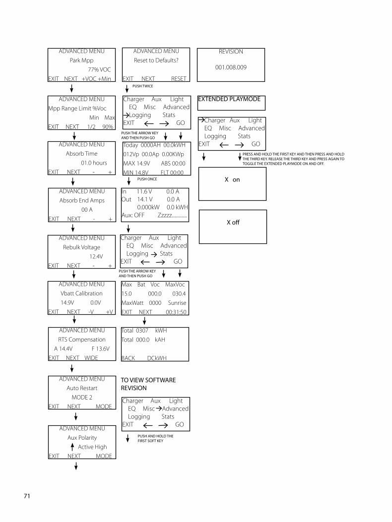
��PB
ADVANCED MENUAbsorb Time
01.0 hours EXIT NEXT - +
ADVANCED MENURebulk Voltage
12.4V EXIT NEXT - +
ADVANCED MENUVbatt Calibration
14.9V 0.0V EXIT NEXT -V +V
ADVANCED MENURTS Compensation
A 14.4V F 13.6V EXIT NEXT WIDE
ADVANCED MENUAuto Restart
MODE 2EXIT NEXT MODE
ADVANCED MENUAbsorb End Amps
00 A EXIT NEXT - +
Today 0000AH 00.0kWH012Vp 00.0Ap 0.00KWpMAX 14.9V ABS 00:00MIN 14.8V FLT 00:00
Max Bat Voc MaxVoc15.0 000.0 030.4MaxWatt 0000 SunriseEXIT NEXT 00:31:50
Total 0307 kWHTotal 000.0 kAH
BACK DCkWH
EXTENDED PLAYMODE
In 11.6 V 0.0 AOut 14.1 V 0.0 A 0.000kW 0.0 kWHAux: OFF Zzzzz.............
PUSH ONCE
Charger Aux Light EQ Misc Advanced Logging StatsEXIT GO
Charger Aux Light EQ Misc Advanced Logging StatsEXIT GO
PUSH THE ARROW KEY AND THEN PUSH GO
PUSH THE ARROW KEY AND THEN PUSH GO
ADVANCED MENUPark Mpp
77% VOC EXIT NEXT +VOC +Min
ADVANCED MENUMpp Range Limit %Voc Min Max EXIT NEXT 1/2 90%
TO VIEW SOFTWARE REVISION
Charger Aux Light EQ Misc Advanced Logging StatsEXIT GO
PUSH AND HOLD THE FIRST SOFT KEY
X off
X on
Charger Aux Light EQ Misc Advanced Logging StatsEXIT GO
PRESS AND HOLD THE FIRST KEY AND THEN PRESS AND HOLD THE THIRD KEY. RELEASE THE THIRD KEY AND PRESS AGAIN TO TOGGLE THE EXTENDED PLAYMODE ON AND OFF.
REVISION
001.008.009
ADVANCED MENUReset to Defaults?
EXIT NEXT RESET
PUSH TWICE
ADVANCED MENUAux Polarity
Active HighEXIT NEXT MODE
��PB
��. Troubleshooting Guide
FLEXmax 80 does not boot/power-up (blank LCD)
• Check the battery connection and polarity. • Reverse polarity or an improper connection will cause power-up issues.• Check the battery breaker. • Ensure that the battery breaker is sized appropriately.• A battery voltage below 10.5VDC may not power up the FLEXmax 80 (measure the battery-side
of wire lugs).• If the FLEXmax 80 still does not power up, call the factory for additional support.
FLEXmax 80 is always SLEEPING
• If the battery voltage is at or above the ABSORB voltage set point (compensated ABSORB voltage), the FLEXmax 80 will not wake up.
• The PV voltage has to be at least two volts greater than the battery voltage for the initial wakeup.• Check the PV array breaker (or fuse).• Confirm the PV array breaker (or fuse) is sized appropriately.• Which State (in MISC Menu) is it at? Is it transitioning between 00 and 01? Is it in GT mode and
connected to a MATE? • GT mode is only applicable with a HUB 4 or HUB 10 installations with a grid-tie compatible
MATE.• Does the PV array voltage on the display rise with the PV breaker OFF, but reads 000 with the PV
breaker on? • If so, the PV array polarity connection on the FLEXmax 80 maybe reversed or the PV lines
could be shorted.• Does the PV voltage still read 000 with the PV breaker off after a minute? • Call the factory for support.• Have you checked the short circuit current of the PV array? • Use a multi-meter to determine if a short circuit current is detected. The short circuit current test will not harm the array.
FLEXmax 80 not producing expected power
• Clouds, partial shading, or dirty panels can cause poor performance.The lower current limit set point in the Charger menu will yield a loss of power or poor performance symptoms.
•
Be sure to check out the OutBack customer and user forum at www.outbackpower.com/forum/ for more FLEXmax 80 information.
��PB
• Are the batteries charged? Is the FLEXmax 80 in the Absorbing or Float stage? If either case is true, the FLEXmax 80 will produce enough power to regulate the voltage at the ABSORB or FLOAT set point voltage, therefore, requiring less power in these modes.• What is the short circuit current of the PV array? Use a multi-meter to determine if a short circuit current is as expected. There might be a loose PV array connection.• If the PV array voltage close to the battery voltage, the panels could be warm/hot causing the Maximum Power Point to be at or lower than the battery voltage.• Is it in U-Pick mode?
FLEXmax 80 is not equalizing
• Has the EQ cycle been initiated? • In the EQ Menu, press START to begin process. When the EQ cycle has been initiated, EQ-MPPT will be displayed.• The EQ cycle has been initiated, but the battery is not equalizing. • The EQ cycle will begin when the target EQ set point voltage has been reached. A small array or cloudy weather will delay the EQ cycle. Accordingly, running too many AC and/or DC loads will delay the EQ cycle, too.• An EQ set point that is too high relative to the battery voltage will delay the EQ cycle.• If the PV array voltage is close to the battery voltage, the panels could be warm/hot causing the Maximum Power Point to be at or lower than the battery voltage which can delay the EQ cycle.
FLEXmax 80 Battery Temperature Compensated Voltage
• Only the OutBack RTS (remote temperature sensor) can be used with the FLEXmax 80.• The battery voltage can rise above the ABSORBING and FLOAT voltage set points if the battery
temperature is < 77°F or fall below the ABSORBING and FLOAT voltage if the battery temperature is > 77°F.
• Why does the FLEXmax 80 show BatTmpErr on the STATUS screen? • The RTS is faulty or damaged. Disconnect the RTS from the RTS jack to resume
normal operation.
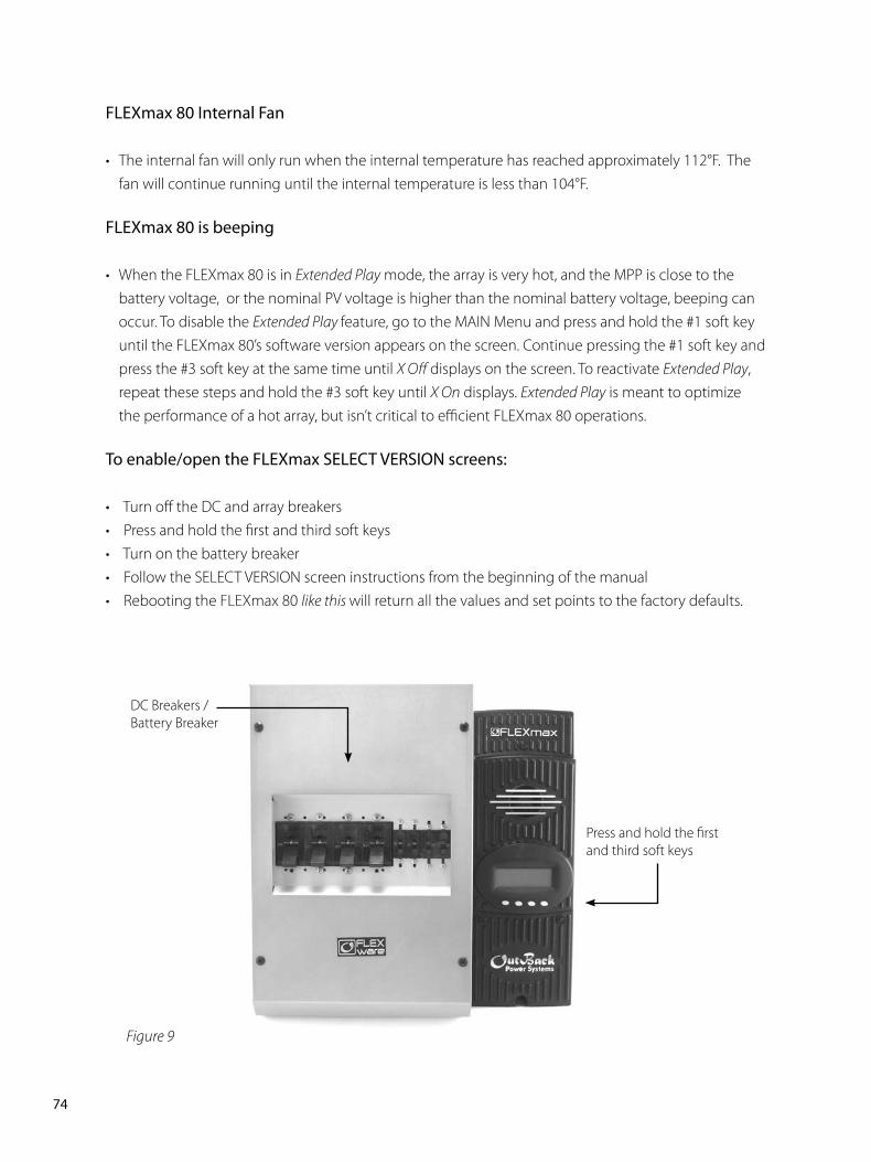
��PB
FLEXmax 80 Internal Fan
• The internal fan will only run when the internal temperature has reached approximately 112°F. The fan will continue running until the internal temperature is less than 104°F.
FLEXmax 80 is beeping
• When the FLEXmax 80 is in Extended Play mode, the array is very hot, and the MPP is close to the battery voltage, or the nominal PV voltage is higher than the nominal battery voltage, beeping can occur. To disable the Extended Play feature, go to the MAIN Menu and press and hold the #1 soft key until the FLEXmax 80’s software version appears on the screen. Continue pressing the #1 soft key and press the #3 soft key at the same time until X Off displays on the screen. To reactivate Extended Play, repeat these steps and hold the #3 soft key until X On displays. Extended Play is meant to optimize the performance of a hot array, but isn’t critical to efficient FLEXmax 80 operations.
To enable/open the FLEXmax SELECT VERSION screens:
• Turn off the DC and array breakers• Press and hold the first and third soft keys• Turn on the battery breaker• Follow the SELECT VERSION screen instructions from the beginning of the manual• Rebooting the FLEXmax 80 like this will return all the values and set points to the factory defaults.
DC Breakers /Battery Breaker
Press and hold the first and third soft keys
Figure 9
��PB
��. Typical Array Sizing GuideBelow is a list of recommended array sizing for the FLEXmax 80 for various nominal voltage batteries: Nominal Battery Voltage Recommended Array Size (in watts, Standard Test Conditions)
12V 1250W 24V 2500W 36V 3750W 48V 5000W 60V 6250W
The FLEXmax 80 PV MPPT Charge Controller is capable of an input open circuit voltage (VOC) of up to 150 VDC. Cooler climates can cause the VOC to rise above the panel VOC rating. In climates that observe temperatures less than approximately 5° F, a VOC greater than 125 VDC is not recommended.
When sizing an array, it is recommended that the nominal array voltage be higher than the nominal battery voltage. Below is a list of recommended nominal array sizing:
Nominal Battery Voltage Nominal Array Voltage (recommended) 12V 24V (or higher)* 24V 36V (or higher)* 36V 48V (or higher)* 48V 60 V (or higher)* 60V 60V (low temp is less than 5°F) or 72V (low temp is greater than 5°F)
* When sizing an array to charge controller with a distance of 70 feet or greater, OutBack recommends the nominal array voltage be slightly higher than the recommended nominal array voltage. Example: A 36VDC nominal array recharging a 12V nominal battery with an array to charge controller distance of about 70 feet or greater. Sizing the nominal array voltage higher than the nominal battery voltage ensures that the Maximum Power Point is always above the battery voltage. The Maximum Power Point will decrease as the panels warm up, thus lowering the output of the array. The FLEXmax 80 Charge Controller will not be able to boost the output if the Maximum Power Point of the array is at or lower than the battery voltage.
��PB
�8. STANDARD vs. AUSTRALIAN DEFAULT SETTINGSThe Australian version FLEXmax 80 has a few default settings that differ from the Standard version default settings. However, there are no differences in performance and efficiency between the two versions. The Standard and Australian version can be identified as follows:
Standard Version Australian Version
Below are a few default setting differences between the Standard and Australian version.
Settings Standard Australian Charger Absorb Float Absorb Float 12V 14.4V 13.6V 14.4V 13.8V 24V 28.8V 27.2V 28.8V 27.6V 36V 43.2V 40.8V 43.2V 41.4V 48V 57.6V 54.4V 57.6V 55.2V 60V 72.0V 68.0V 72.0V 69.0V
Equalize Equalize Volts Equalize Volts 12V 14.4 14.7 24V 28.8 29.4 36V 43.2 44.1 48V 57.6 58.8 60V 72.0 73.5 Equalize Time 01 Hours 03 Hours
OutBack 12VPower
SystemsFLEXmax80
OutBack 12VPower
SystemsFLEXmax80-AU
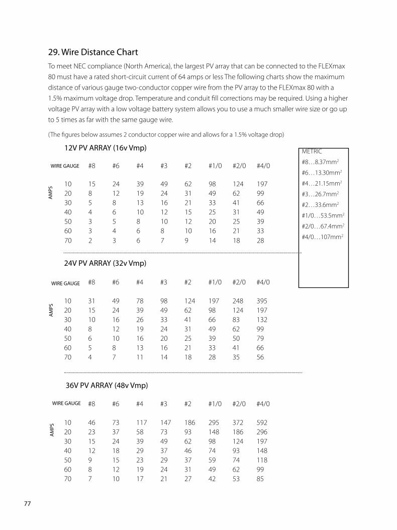
��PB
��. Wire Distance ChartTo meet NEC compliance (North America), the largest PV array that can be connected to the FLEXmax 80 must have a rated short-circuit current of 64 amps or less The following charts show the maximum distance of various gauge two-conductor copper wire from the PV array to the FLEXmax 80 with a 1.5% maximum voltage drop. Temperature and conduit fill corrections may be required. Using a higher voltage PV array with a low voltage battery system allows you to use a much smaller wire size or go up to 5 times as far with the same gauge wire.
(The figures below assumes 2 conductor copper wire and allows for a 1.5% voltage drop)
��V PV ARRAY (��v Vmp) #8 #6 #4 #3 #2 #1/0 #2/0 #4/0
10 15 24 39 49 62 98 124 19720 8 12 19 24 31 49 62 9930 5 8 13 16 21 33 41 6640 4 6 10 12 15 25 31 4950 3 5 8 10 12 20 25 3960 3 4 6 8 10 16 21 3370 2 3 6 7 9 14 18 28
WIRE GAUGE
AM
PS
��V PV ARRAY (��v Vmp) #8 #6 #4 #3 #2 #1/0 #2/0 #4/0
10 31 49 78 98 124 197 248 39520 15 24 39 49 62 98 124 19730 10 16 26 33 41 66 83 13240 8 12 19 24 31 49 62 9950 6 10 16 20 25 39 50 7960 5 8 13 16 21 33 41 6670 4 7 11 14 18 28 35 56
WIRE GAUGE
AM
PS
��V PV ARRAY (�8v Vmp)
#8 #6 #4 #3 #2 #1/0 #2/0 #4/0
10 46 73 117 147 186 295 372 59220 23 37 58 73 93 148 186 29630 15 24 39 49 62 98 124 19740 12 18 29 37 46 74 93 14850 9 15 23 29 37 59 74 11860 8 12 19 24 31 49 62 9970 7 10 17 21 27 42 53 85
WIRE GAUGE
AM
PS
METRIC
#8…8.37mm2
#6…13.30mm2
#4…21.15mm2
#3…26.7mm2
#2…33.6mm2
#1/0…53.5mm2
#2/0…67.4mm2
#4/0…107mm2
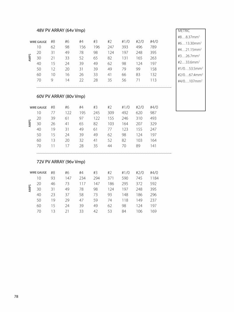
�8PB
�8V PV ARRAY (��v Vmp)
#8 #6 #4 #3 #2 #1/0 #2/0 #4/010 62 98 156 196 247 393 496 78920 31 49 78 98 124 197 248 39530 21 33 52 65 82 131 165 26340 15 24 39 49 62 98 124 19750 12 20 31 39 49 79 99 15860 10 16 26 33 41 66 83 13270 9 14 22 28 35 56 71 113
�0V PV ARRAY (80v Vmp)
#8 #6 #4 #3 #2 #1/0 #2/0 #4/010 77 122 195 245 309 492 620 98720 39 61 97 122 155 246 310 49330 26 41 65 82 103 164 207 32940 19 31 49 61 77 123 155 24750 15 24 39 49 62 98 124 19760 13 20 32 41 52 82 103 16470 11 17 28 35 44 70 89 141
��V PV ARRAY (��v Vmp)
#8 #6 #4 #3 #2 #1/0 #2/0 #4/010 93 147 234 294 371 590 745 118420 46 73 117 147 186 295 372 59230 31 49 78 98 124 197 248 39540 23 37 58 73 93 148 186 29650 19 29 47 59 74 118 149 23760 15 24 39 49 62 98 124 19770 13 21 33 42 53 84 106 169
WIRE GAUGE
AM
PS
WIRE GAUGE
AM
PS
WIRE GAUGE
AM
PSMETRIC
#8…8.37mm2
#6…13.30mm2
#4…21.15mm2
#3…26.7mm2
#2…33.6mm2
#1/0…53.5mm2
#2/0…67.4mm2
#4/0…107mm2
��PB
�0. WIRE AND DISCONNECT SIZING
The FLEXmax 80 is a buck type converter with the following properties:
• 80 amp DC output current limit (default setting)
• Listed to operate continuously at 80 amps (40°C/104° F)
With an 80 amp FLEXmax 80 output current limit and PV array output higher than 80 amps offers little,
if any, current boosting or Maximum Power Point Tracking advantage; in effect, any excess power
beyond 80 amps is lost.
For NEC* compliance and the FLEXmax 80’s 80 amp output rating / MPPT capabilities, the largest PV
array input must not exceed a rated short-circuit current of 64 amps.
Battery Side of the Controller
• All OutBack Power circuit breakers (OBB-XX) are 100% continuous-rated type breakers
• The conductors connected to the breakers must have a 125% safety factor applied (i.e., an 80 amp
breaker must have a 100-amp conductor connected when used at its full 80-amp rating)
PV Side of the Controller
• UL* requires a 125% safety multiplier (before NEC calculations)
• NEC* requires a 125% safety multiplier (after UL calculations).
• The 156% safety multiplier is specific in the NEC* to PV applications only – this “dual” 125% multiplier
is used because a PV array can produce above its rated output in some conditions.
NEC Compliance
• When the 156% safety multiplier is applied, the resulting conductor amperage required is still 100-
amps (1.56 X 64A) and an 80 amp breaker may be used (100% continuous duty rated breaker).
• When a PV array is configured for a higher nominal input voltage (such as 72V PV array), the PV input
conductor can be sized smaller depending on the step-down ratio and the maximum short circuit
current available.
NOTE: The input breaker must also be sized smaller; it cannot be the normal 80 amp with conductor smaller than #4 AWG. (21.1mm2)
* North America
80PB
��. WIRING COMPARTMENT
The wiring terminals and compartment of the FLEXmax 80 Charge Controller are fully compliant with all NEC and UL requirements. The following summary is specific for North American applications where NEC and UL standards govern installations.
Recommended Conductor and Breaker Sizes for the FLEXmax 80
Output Rating at 80 amps
If the output current of the Flexmax 80 is expected to reach the maximum output level of 80 amps:
• #3 or #2 AWG conductor must be used with an 80 amp breaker (100% continuous duty rated breaker)• The minimum recommended battery conductor is #3* AWG • The maximum recommended battery conductor is #2** AWG
* #3 AWG conductor can be installed through the side, back or bottom knockouts** #2 AWG conductor must be installed on the side or back knockout to meet the specific UL requirements for wire bending room standards - 1” conduit knockout is approved for up to three #2 AWG conductors - For short conduit runs (less than 24”), a higher conduit fill is acceptable* —three #2 AWG wires
Please reference the NEC Appendix “C” in the back of the book. You must refer to the table representing the type of conduit you will be using to find the maximum number of conductors allowed within the conduit you will be using.
Output Rating less than �� amps
If the output current of the FLEXmax 80 is expected to be less than 64 amps:
• An 80 amp breaker and #4 AWG conductors can be used on the battery side.• The PV array short circuit current must be less than 48 amps and the #4 conductor will be acceptable
with an 80 amp breaker.
METRIC
#4…21.15mm2
#3…26.7mm2
#2…33.6mm2

8�PB
��. FLEXmax 80 MULTI-STAGE BATTERY CHARGING
The FLEXmax 80 charge controller is a sophisticated, multi-stage battery charger that uses several regulation stages to allow fast recharging of the battery system while ensuring a long battery life. This process can be used with both sealed and non-sealed batteries. The FLEXmax 80 has a preset recharging voltage set points (Absorb & Float) for the selected nominal battery voltage, however, always follow the battery manufacturer’s recommended charging regulation voltages. The FLEXmax 80 charging regulation stages correspond to the chart in Figure 10.
Figure 10
NOTE: In BULK, the FLEXmax 80 will charge as long as necessary to complete the cycle, regardless of the timer’s set points.
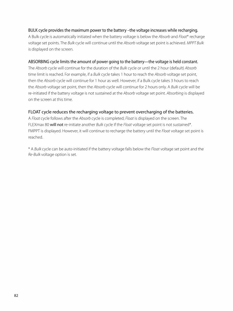
8�PB
BULK cycle provides the maximum power to the battery –the voltage increases while recharging.A Bulk cycle is automatically initiated when the battery voltage is below the Absorb and Float* recharge voltage set points. The Bulk cycle will continue until the Absorb voltage set point is achieved. MPPT Bulk is displayed on the screen.
ABSORBING cycle limits the amount of power going to the battery—the voltage is held constant.The Absorb cycle will continue for the duration of the Bulk cycle or until the 2 hour (default) Absorb time limit is reached. For example, if a Bulk cycle takes 1 hour to reach the Absorb voltage set point, then the Absorb cycle will continue for 1 hour as well. However, if a Bulk cycle takes 3 hours to reach the Absorb voltage set point, then the Absorb cycle will continue for 2 hours only. A Bulk cycle will be re-initiated if the battery voltage is not sustained at the Absorb voltage set point. Absorbing is displayed on the screen at this time.
FLOAT cycle reduces the recharging voltage to prevent overcharging of the batteries.A Float cycle follows after the Absorb cycle is completed; Float is displayed on the screen. The FLEXmax 80 will not re-initiate another Bulk cycle if the Float voltage set point is not sustained*. FMPPT is displayed. However, it will continue to recharge the battery until the Float voltage set point is reached.
* A Bulk cycle can be auto-initiated if the battery voltage falls below the Float voltage set point and the Re-Bulk voltage option is set.
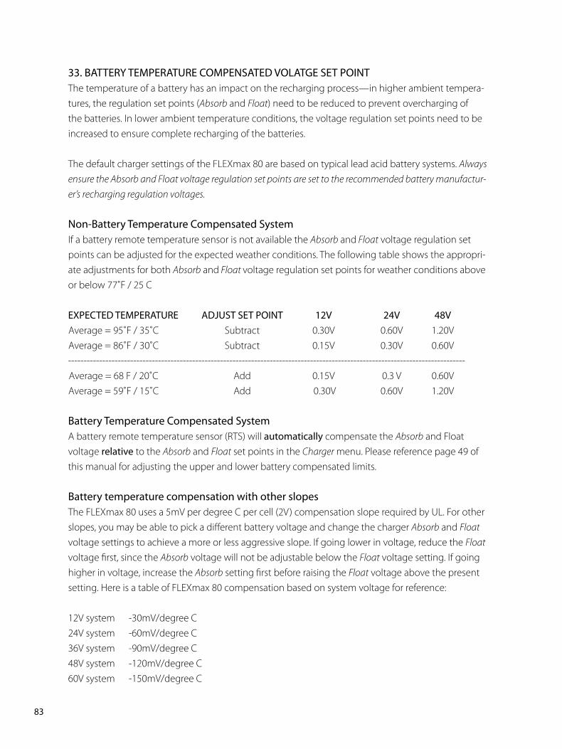
8�PB
��. BATTERY TEMPERATURE COMPENSATED VOLATGE SET POINTThe temperature of a battery has an impact on the recharging process—in higher ambient tempera-tures, the regulation set points (Absorb and Float) need to be reduced to prevent overcharging of the batteries. In lower ambient temperature conditions, the voltage regulation set points need to be increased to ensure complete recharging of the batteries.
The default charger settings of the FLEXmax 80 are based on typical lead acid battery systems. Always ensure the Absorb and Float voltage regulation set points are set to the recommended battery manufactur-er’s recharging regulation voltages.
Non-Battery Temperature Compensated SystemIf a battery remote temperature sensor is not available the Absorb and Float voltage regulation set points can be adjusted for the expected weather conditions. The following table shows the appropri-ate adjustments for both Absorb and Float voltage regulation set points for weather conditions above or below 77˚F / 25 C
EXPECTED TEMPERATURE ADJUST SET POINT ��V ��V �8V Average = 95˚F / 35˚C Subtract 0.30V 0.60V 1.20V Average = 86˚F / 30˚C Subtract 0.15V 0.30V 0.60V-------------------------------------------------------------------------------------------------------------------------------- Average = 68 F / 20˚C Add 0.15V 0.3 V 0.60V Average = 59˚F / 15˚C Add 0.30V 0.60V 1.20V
Battery Temperature Compensated SystemA battery remote temperature sensor (RTS) will automatically compensate the Absorb and Float voltage relative to the Absorb and Float set points in the Charger menu. Please reference page 49 of this manual for adjusting the upper and lower battery compensated limits.
Battery temperature compensation with other slopesThe FLEXmax 80 uses a 5mV per degree C per cell (2V) compensation slope required by UL. For other slopes, you may be able to pick a different battery voltage and change the charger Absorb and Float voltage settings to achieve a more or less aggressive slope. If going lower in voltage, reduce the Float voltage first, since the Absorb voltage will not be adjustable below the Float voltage setting. If going higher in voltage, increase the Absorb setting first before raising the Float voltage above the present setting. Here is a table of FLEXmax 80 compensation based on system voltage for reference:
12V system -30mV/degree C24V system -60mV/degree C36V system -90mV/degree C48V system -120mV/degree C60V system -150mV/degree C
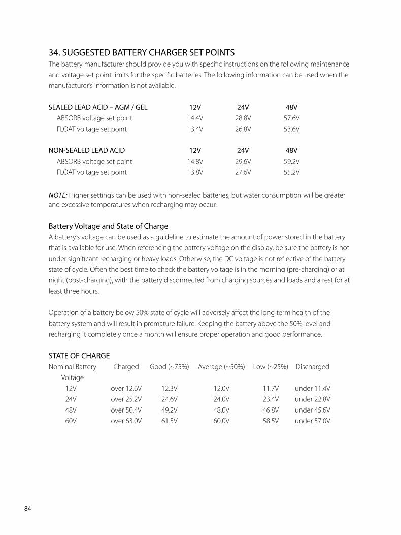
8�PB
��. SUGGESTED BATTERY CHARGER SET POINTSThe battery manufacturer should provide you with specific instructions on the following maintenance and voltage set point limits for the specific batteries. The following information can be used when the manufacturer’s information is not available.
SEALED LEAD ACID – AGM / GEL ��V ��V �8V ABSORB voltage set point 14.4V 28.8V 57.6V FLOAT voltage set point 13.4V 26.8V 53.6V
NON-SEALED LEAD ACID ��V ��V �8V ABSORB voltage set point 14.8V 29.6V 59.2V FLOAT voltage set point 13.8V 27.6V 55.2V
NOTE: Higher settings can be used with non-sealed batteries, but water consumption will be greater and excessive temperatures when recharging may occur.
Battery Voltage and State of ChargeA battery’s voltage can be used as a guideline to estimate the amount of power stored in the battery that is available for use. When referencing the battery voltage on the display, be sure the battery is not under significant recharging or heavy loads. Otherwise, the DC voltage is not reflective of the battery state of cycle. Often the best time to check the battery voltage is in the morning (pre-charging) or at night (post-charging), with the battery disconnected from charging sources and loads and a rest for at least three hours.
Operation of a battery below 50% state of cycle will adversely affect the long term health of the battery system and will result in premature failure. Keeping the battery above the 50% level and recharging it completely once a month will ensure proper operation and good performance.
STATE OF CHARGENominal Battery Charged Good (~75%) Average (~50%) Low (~25%) Discharged Voltage 12V over 12.6V 12.3V 12.0V 11.7V under 11.4V 24V over 25.2V 24.6V 24.0V 23.4V under 22.8V 48V over 50.4V 49.2V 48.0V 46.8V under 45.6V 60V over 63.0V 61.5V 60.0V 58.5V under 57.0V
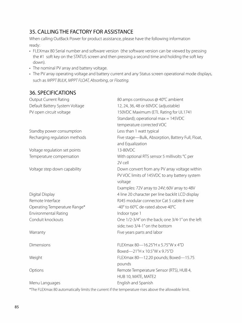
8�PB
��. CALLING THE FACTORY FOR ASSISTANCEWhen calling OutBack Power for product assistance, please have the following informationready:• FLEXmax 80 Serial number and software version (the software version can be viewed by pressing
the #1 soft key on the STATUS screen and then pressing a second time and holding the soft key down).
• The nominal PV array and battery voltage.• The PV array operating voltage and battery current and any Status screen operational mode displays,
such as MPPT BULK, MPPT FLOAT, Absorbing, or Floating.
��. SPECIFICATIONSOutput Current Rating 80 amps continuous @ 40°C ambient Default Battery System Voltage 12, 24, 36, 48 or 60VDC (adjustable) PV open circuit voltage 150VDC Maximum (ETL Rating for UL1741 Standard); operational max = 145VDC temperature corrected VOCStandby power consumption Less than 1 watt typicalRecharging regulation methods Five stage—Bulk, Absorption, Battery Full, Float, and EqualizationVoltage regulation set points 13-80VDCTemperature compensation With optional RTS sensor 5 millivolts °C per 2V cellVoltage step down capability Down convert from any PV array voltage within PV VOC limits of 145VDC to any battery system voltage Examples: 72V array to 24V; 60V array to 48VDigital Display 4 line 20 character per line backlit LCD displayRemote Interface RJ45 modular connector Cat 5 cable 8 wireOperating Temperature Range* -40° to 60°C de-rated above 40°CEnvironmental Rating Indoor type 1Conduit knockouts One 1/2-3/4” on the back; one 3/4-1” on the left side; two 3/4-1” on the bottomWarranty Five years parts and labor Dimensions FLEXmax 80—16.25”H x 5.75”W x 4”D Boxed—21”H x 10.5”W x 9.75”DWeight FLEXmax 80—12.20 pounds; Boxed—15.75 poundsOptions Remote Temperature Sensor (RTS), HUB 4, HUB 10, MATE, MATE2Menu Languages English and Spanish*The FLEXmax 80 automatically limits the current if the temperature rises above the allowable limit.
8�PB
FIVE YEAR LIMITED WARRANTY INFORMATION
FLEXmax Products
OutBack Power Systems, Inc. (“OutBack”) provides a five year (5) limited warranty (“Warranty”) against defects in materials and workmanship for its FLEXmax products (“Products”) if installed in fixed location applications.
For this Warranty to be valid, the Product purchaser must complete and submit the applicable Product registration card within ninety (90) days of the eligible Product’s first retail sale. This Warranty applies to the original OutBack Product purchaser, and is transferable only if the Product remains installed in the original use location. The warranty does not apply to any Product or Product part that has been modified or damaged by the following:
• Installation or Removal;• Alteration or Disassembly;• Normal Wear and Tear;• Accident or Abuse;• Corrosion;• Lightning;• Repair or service provided by an unauthorized repair facility;• Operation contrary to manufacturer product instructions;• Fire, Floods or Acts of God; • Shipping or Transportation; • Incidental or consequential damage caused by other components of the power system;• Any product whose serial number has been altered, defaced or removed; or• Any other event not foreseeable by OutBack.
OutBack’s liability for any defective Product, or any Product part, shall be limited to the repair or replacement of the Product, at OutBack’s discretion. OutBack does not warrant or guarantee workmanship performed by any person or firm installing its Products. This Warranty does not cover the costs of installation, removal, shipping (except as described below), or reinstallation of Products.
Revision.2007-10-02
8�PB
To request warranty service, you must contact OutBack Technical Services at (360) 435-6030 or [email protected] within the effective warranty period. If warranty service is required, OutBack will issue a Return Material Authorization (RMA) number. A request for an RMA number requires all of the following information:
1. Proof-of-purchase in the form of a copy of the original Product purchase invoice or receipt confirming the Product model number and serial number;
2. Description of the problem; and3. Shipping address for the repaired or replacement equipment.
After receiving the RMA number, pack the Product(s) authorized for return, along with a copy of the original purchase invoice and warranty certificate, in the original Product shipping container(s) or packaging providing equivalent protection and mark the outside clearly with the RMA number. The sender must prepay all shipping charges, and insure the shipment, or accept the risk of loss or damage during shipment. OutBack is not responsible for shipping damage caused by improperly packaged Products, the repairs this damage might require, or the costs of these repairs. If, upon receipt of the Product, OutBack determines the Product is defective and that the defect is covered under the terms of this Warranty, OutBack will then and only then ship a repaired or replacement Product to the purchaser freight prepaid, non-expedited, using a carrier of OutBack’s choice within the continental United States, where applicable
Shipments to other locations will be made freight collect. The warranty period of any repaired or replacement Product is twelve (12) months from the date of shipment from OutBack, or the remainder of the initial warranty term, which ever is greater.
THIS LIMITED WARRANTY IS THE EXCLUSIVE WARRANTY APPLICABLE TO OUTBACK PRODUCTS. OUTBACK EXPRESSLY DISCLAIMS ANY OTHER EXPRESS OR IMPLIED WARRANTIES OF ITS PRODUCTS, INCLUDING BUT NOT LIMITED TO ANY IMPLIED WARRANTIES OF MERCHANTABILITY OR FITNESS FOR A PARTICULAR PURPOSE. OUTBACK ALSO EXPRESSLY LIMITS ITS LIABILITY IN THE EVENT OF A PRODUCT DEFECT TO REPAIR OR REPLACEMENT IN ACCORDANCE WITH THE TERMS OF THIS LIMITED WARRANTY AND EXCLUDES ALL LIABILITY FOR INCIDENTAL OR CONSEQUENTIAL DAMAGES, INCLUDING WITHOUT LIMITATION ANY LIABILITY FOR PRODUCTS NOT BEING AVAILABLE FOR USE OR LOST REVENUES OR PROFITS, EVEN IF IT IS MADE AWARE OF SUCH POTENTIAL DAMAGES. SOME STATES (OR JURISDICTIONS) MAY NOT ALLOW THE EXCLUSION OR LIMITATION OF WARRANTIES OR DAMAGES, SO THE ABOVE EXCLUSIONS OR LIMITATIONS MAY NOT APPLY TO YOU.
Revision.2007-10-02
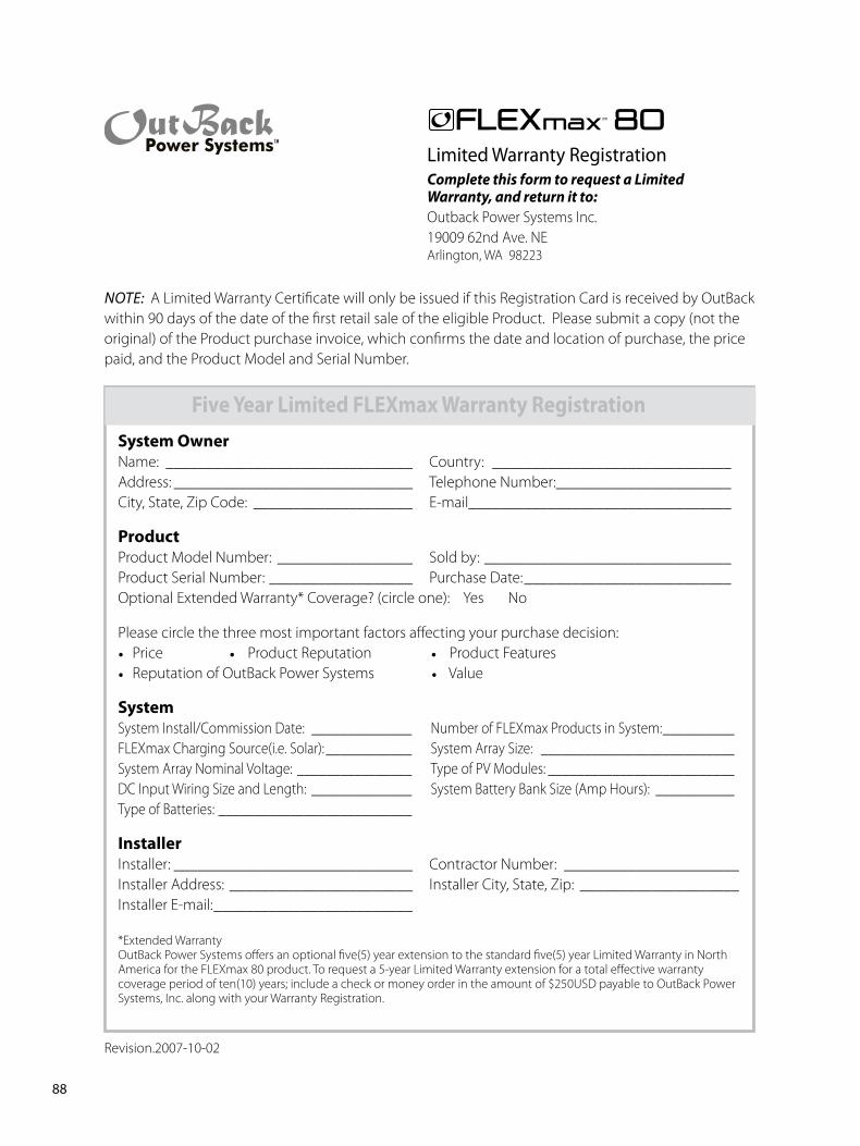
88PB
Limited Warranty RegistrationComplete this form to request a Limited Warranty, and return it to:Outback Power Systems Inc.19009 62nd Ave. NEArlington, WA 98223
NOTE: A Limited Warranty Certificate will only be issued if this Registration Card is received by OutBack within 90 days of the date of the first retail sale of the eligible Product. Please submit a copy (not the original) of the Product purchase invoice, which confirms the date and location of purchase, the price paid, and the Product Model and Serial Number.
FiveYearLimitedFLEXmaxWarrantyRegistrationSystemOwnerName: _______________________________ Country: ______________________________Address: ______________________________ Telephone Number: ______________________City, State, Zip Code: ____________________ E-mail_________________________________
ProductProduct Model Number: _________________ Sold by: _______________________________Product Serial Number: __________________ Purchase Date: __________________________Optional Extended Warranty* Coverage? (circle one): Yes No
Please circle the three most important factors affecting your purchase decision:• Price • Product Reputation • Product Features • Reputation of OutBack Power Systems • Value SystemSystem Install/Commission Date: ______________ Number of FLEXmax Products in System: __________FLEXmax Charging Source(i.e. Solar): ____________ System Array Size: ___________________________System Array Nominal Voltage: ________________ Type of PV Modules: __________________________DC Input Wiring Size and Length: ______________ System Battery Bank Size (Amp Hours): ___________Type of Batteries: ___________________________ InstallerInstaller: ______________________________ Contractor Number: ______________________Installer Address: _______________________ Installer City, State, Zip: ____________________Installer E-mail: _________________________
*Extended Warranty OutBack Power Systems offers an optional five(5) year extension to the standard five(5) year Limited Warranty in North America for the FLEXmax 80 product. To request a 5-year Limited Warranty extension for a total effective warranty coverage period of ten(10) years; include a check or money order in the amount of $250USD payable to OutBack Power Systems, Inc. along with your Warranty Registration.
maxTM 80
Revision.2007-10-02
8�PB
EU DECLARATION OF CONFORMITYAccording to ISO / IEC Guide 22 and EN 45014
Product Type: Photovoltaic Charge Controller
Product Model Number: FLEXmax 80
This product complies with the following EU directives:
Electromagnetic Compatibility 8�/���/EEC, “Council Directive of � May ��8�
On the approximation of the laws of member States relating to Electromagnetic compatibility”
Low Voltage Directive ��/��/EEC, “Council Directive of �� February ���� on the harmonization of
the laws of Member States relating to electrical equipment for use within certain voltage limits”
The compliance of the above mentioned product with the directives and the following essential
requirements is hereby confirmed:
Emissions Immunity Safety
EN 61000-6-3 (2001) EN 61000-6-1 (2001) EN 60335-1 Battery Chargers
EN 60335-2-29Battery Chargers
All associated technical files are located in the Engineering Department at OutBack Power Systems Inc.,
Arlington, Washington, USA.
As the manufacturer, we declare under our sole responsibility that the above-mentioned product
complies with the above-named directives.
19009 62nd Ave. NEArlington, WA. 98223 USA(360) 435-6030
�0PB
OWNER’S SYSTEM INFORMATION
Date of Purchase: __________________________________________________________________
Vendor: __________________________________________________________________________
Date of Installation: _________________________________________________________________
Installer: _________________________________________________________________________
Installer Contact Information: _________________________________________________________
FLEXmax 80 Serial Number: __________________________________________________________
Battery Voltage: ____________________________________________________________________
PV Voltage: _______________________________________________________________________
PV Module Type and Manufacturer: ____________________________________________________
Array Wattage: _____________________________________________________________________
NOTES: __________________________________________________________________________
_________________________________________________________________________________

900-0082-01-00 REV A
European Sales OfficeC/ Castelló, ��
088�0 - Sant Boi de LlobregatBARCELONA, España
Phone: +��.��.���.���8
Corporate Office19009 62nd Avenue NEArlington, WA USAPhone: (+1) 360-435-6030
www.outbackpower.com