Embed Size (px)
Citation preview
McGraw-Hill © 2013 The McGraw-Hill Companies Inc. All rights reserved.
ElectricityElectricity
Principles & ApplicationsPrinciples & ApplicationsEighth EditionEighth Edition
Chapter 3Basic Circuits, Laws,and Measurements(student version)
Richard J. Fowler
McGraw-Hill © 2013 The McGraw-Hill Companies Inc. All rights reserved.
3 - 1

McGraw-Hill © 2013 The McGraw-Hill Companies Inc. All rights reserved.
INTRODUCTION
• Circuit Symbols (p 46)
• Circuit Diagrams (p 45)
• Parts of a Circuit (p 45)
• Measuring Electrical Quantities (p 53)
• Calculating Electrical Quantities (p 47)
3 - 2

McGraw-Hill © 2013 The McGraw-Hill Companies Inc. All rights reserved.
Dear Student:
This presentation is arranged in segments. Each segmentis preceded by a Concept Preview slide and is followed by aConcept Review slide. When you reach a Concept Reviewslide, you can return to the beginning of that segment byclicking on the Repeat Segment button. This will allow youto view that segment again, if you want to.
3 - 3

McGraw-Hill © 2013 The McGraw-Hill Companies Inc. All rights reserved.
Concept Preview• Electrical components can be
represented by schematic symbols.• A complete circuit needs a power source,
a load, conductors, and insulation.
• A schematic diagram doesn’t show thephysical layout of the components.
• Insulation, although required, isn’t shown on a schematic diagram.
3 - 4

McGraw-Hill © 2013 The McGraw-Hill Companies Inc. All rights reserved.
+ Terminal
DeviceSymbol
Symbols and Components
Symbol Device
Cell(p 46)
Resistor(p 43+)
3 - 5

McGraw-Hill © 2013 The McGraw-Hill Companies Inc. All rights reserved.
This complete circuit uses the following: •An energy or power source
•A control device
•A load
•Conductors •Insulation (not shown)
(p 45)
3 - 6
McGraw-Hill © 2013 The McGraw-Hill Companies Inc. All rights reserved.
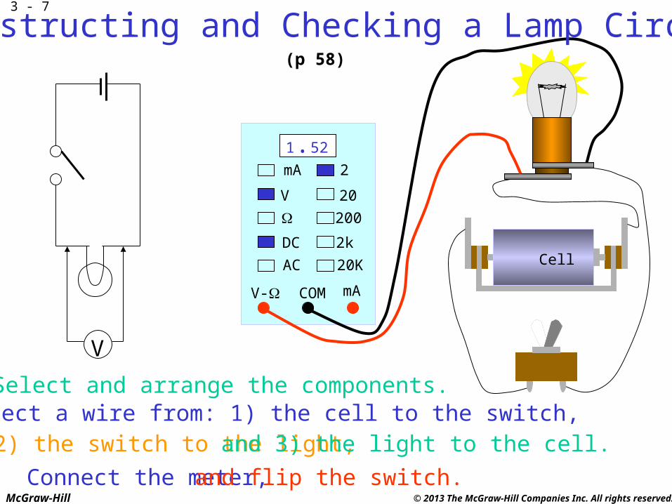
Cell
mA 2
V
DC
AC
20
200
2k
20K
V- COM mA
1.52
V
Select and arrange the components.Connect a wire from: 1) the cell to the switch, 2) the switch to the light, and 3) the light to the cell.
Connect the meter, and flip the switch.
Constructing and Checking a Lamp Circuit(p 58)
3 - 7

McGraw-Hill © 2013 The McGraw-Hill Companies Inc. All rights reserved.
Circuit QuizAn electrical component has a ____ as well as a name.
The long bar on the cell symbol isthe ____ terminal of the cell.
A complete circuit has a ____ ____ that forces current to flow.
A complete circuit often has a ____ ____ that turns the circuit off and on.
A complete circuit has a ____ thatcontrols the current flow.
A complete circuit has ____ thatroute the current .
symbol
positive
power source
control device
load
conductors
3 - 8

McGraw-Hill © 2013 The McGraw-Hill Companies Inc. All rights reserved.
Concept Review• Electrical components can be
represented by schematic symbols.• A complete circuit needs a power source,
a load, conductors, and insulation.
• A schematic diagram doesn’t show thephysical layout of the components.
• Insulation, although required, isn’t shown on a schematic diagram.
Repeat Segment
3 - 9

McGraw-Hill © 2013 The McGraw-Hill Companies Inc. All rights reserved.
Concept Preview• Select the correct function on a
meter before making a measurement.
• Interrupt the circuit to measure current.
• Remove power from the circuitbefore measuring resistance.
• Observe polarity when measuring current or voltage.
3 - 10

McGraw-Hill © 2013 The McGraw-Hill Companies Inc. All rights reserved.
k mAmV V A
+ V A COM - d c a c
MEASURING VOLTAGE
Select the dcVfunction
Connect - lead to - terminal of source
Connect + lead to + terminal of source
R1
1 k
S1
SPSTB1
15 V
(p 58)
3 - 11

McGraw-Hill © 2013 The McGraw-Hill Companies Inc. All rights reserved.
k mAmV V A
+ V A COM - d c a c
Select the dc mA function
R1
1 k
S1
SPSTB1
15 V
MEASURING CURRENT(p 59)
3 - 12

McGraw-Hill © 2013 The McGraw-Hill Companies Inc. All rights reserved.
R1
1 k
S1
SPSTB1
15 V
k mAmV V A
+ V A COM - d c a c
Select the dc mA function
Physicallyinterrupt thecircuit
Connect the - lead so
that electrons enter it
Connect the + lead to the other point
MEASURING CURRENT(p 59)
3 - 13

McGraw-Hill © 2013 The McGraw-Hill Companies Inc. All rights reserved.
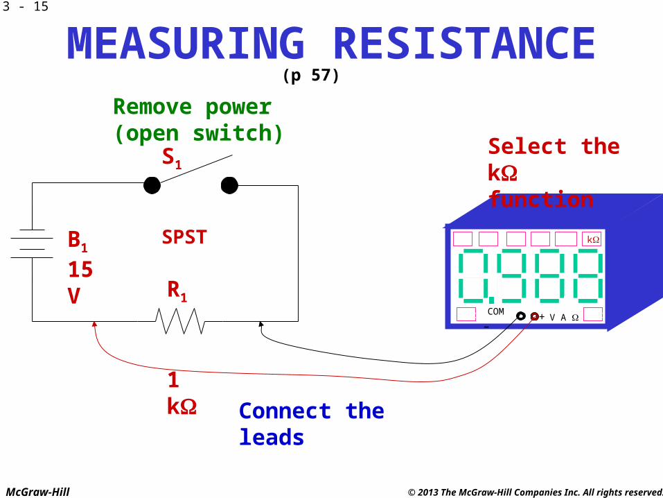
MEASURING RESISTANCE
k mAmV V A
+ V A COM - d c a c
Select the kfunction
R1
1 k
S1
SPSTB1
15 V
(p 57)
3 - 14
McGraw-Hill © 2013 The McGraw-Hill Companies Inc. All rights reserved.
k mAmV V A
+ V A COM - d c a c
Select the kfunction
R1
1 k
S1
SPSTB1
15 V
Remove power(open switch)
Connect the leads
MEASURING RESISTANCE(p 57)
3 - 15

McGraw-Hill © 2013 The McGraw-Hill Companies Inc. All rights reserved.
Measurement QuizSelect the correct ____ of the meter before measuring an electrical quantity.
When measuring voltage, the meter’s positive leadis connected to the ____ terminal of the source.
When measuring current, the meter’s ____ leadreceives electrons from the circuit.
When measuring ____ , the meter is connected tothe points created by interrupting the circuit.
Power is removed from the circuit beforemeasuring ____.
function
positive
negative
current
resistance
3 - 16
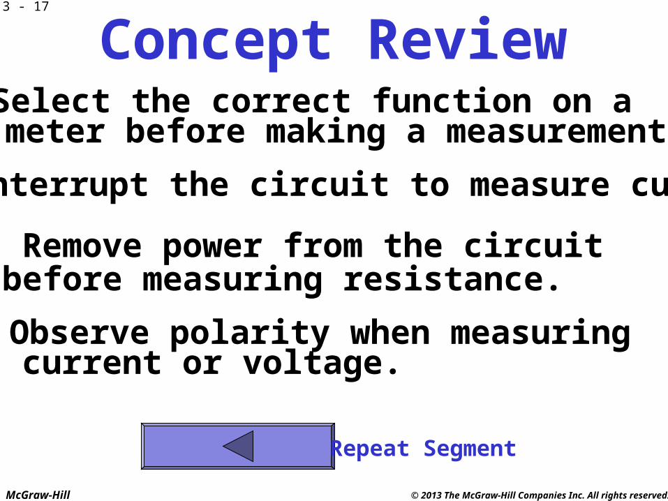
McGraw-Hill © 2013 The McGraw-Hill Companies Inc. All rights reserved.
Concept Review• Select the correct function on a
meter before making a measurement.
• Interrupt the circuit to measure current.
• Remove power from the circuitbefore measuring resistance.
• Observe polarity when measuring current or voltage.
Repeat Segment
3 - 17
McGraw-Hill © 2013 The McGraw-Hill Companies Inc. All rights reserved.
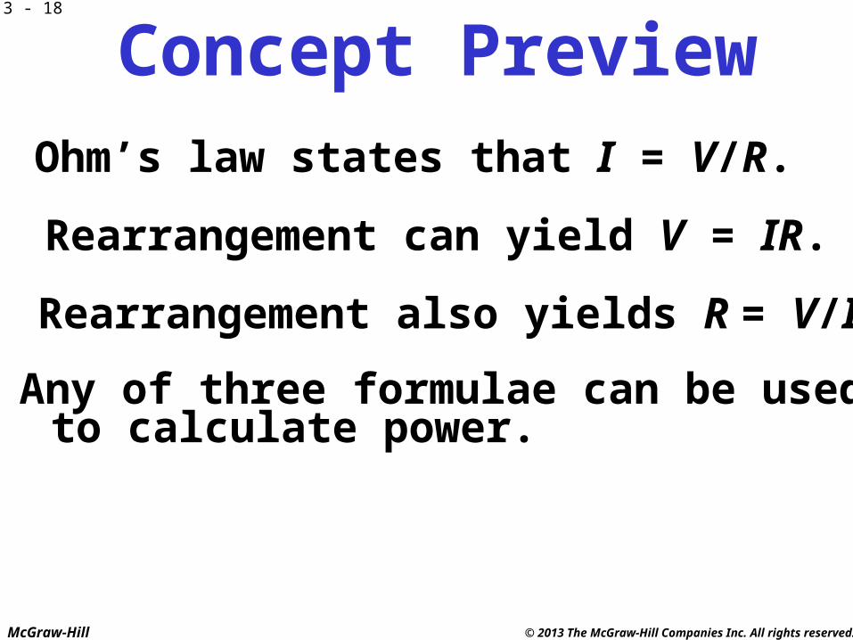
Concept Preview• Ohm’s law states that I = V/R.
• Rearrangement can yield V = IR.
• Rearrangement also yields R = V/I.
• Any of three formulae can be used to calculate power.
3 - 18

McGraw-Hill © 2013 The McGraw-Hill Companies Inc. All rights reserved.
CALCULATING CURRENT
I =VR
= 36 V1800
= 0.02 A = 20 mA
S1
SPST
R
1.8 k
B1
36 V
(p 48)
3 - 19
McGraw-Hill © 2013 The McGraw-Hill Companies Inc. All rights reserved.
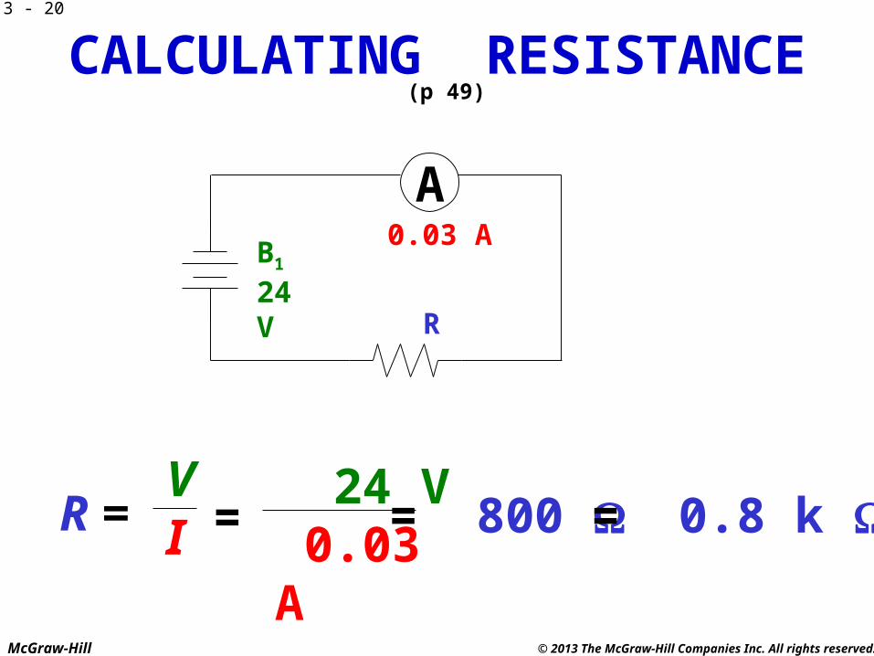
CALCULATING RESISTANCE
R = V I =
24 V 0.03 A
= 800 = 0.8 k
R
B1
24 V
A0.03 A
(p 49)
3 - 20
McGraw-Hill © 2013 The McGraw-Hill Companies Inc. All rights reserved.
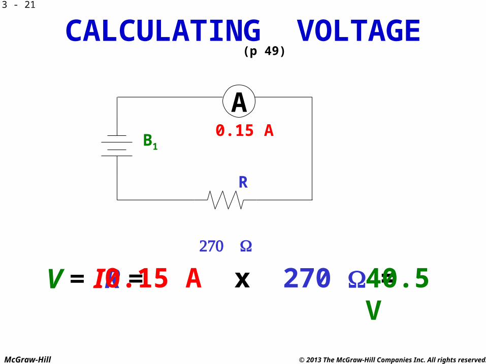
CALCULATING VOLTAGE
V = IR = 0.15 A x 270 = 40.5 V
R
B1
A0.15 A
(p 49)
3 - 21

McGraw-Hill © 2013 The McGraw-Hill Companies Inc. All rights reserved.
CALCULATING POWER
P =
0.2 A
IV = 0.2 A x 54 V= 10.8 W
V54 V
P = I2R = 0.2 A x 0.2 A x 270 = 10.8 W
P = V2/R = (54 V x 54 V) / 270 = 10.8 W
A(p 49)
3 - 22
McGraw-Hill © 2013 The McGraw-Hill Companies Inc. All rights reserved.
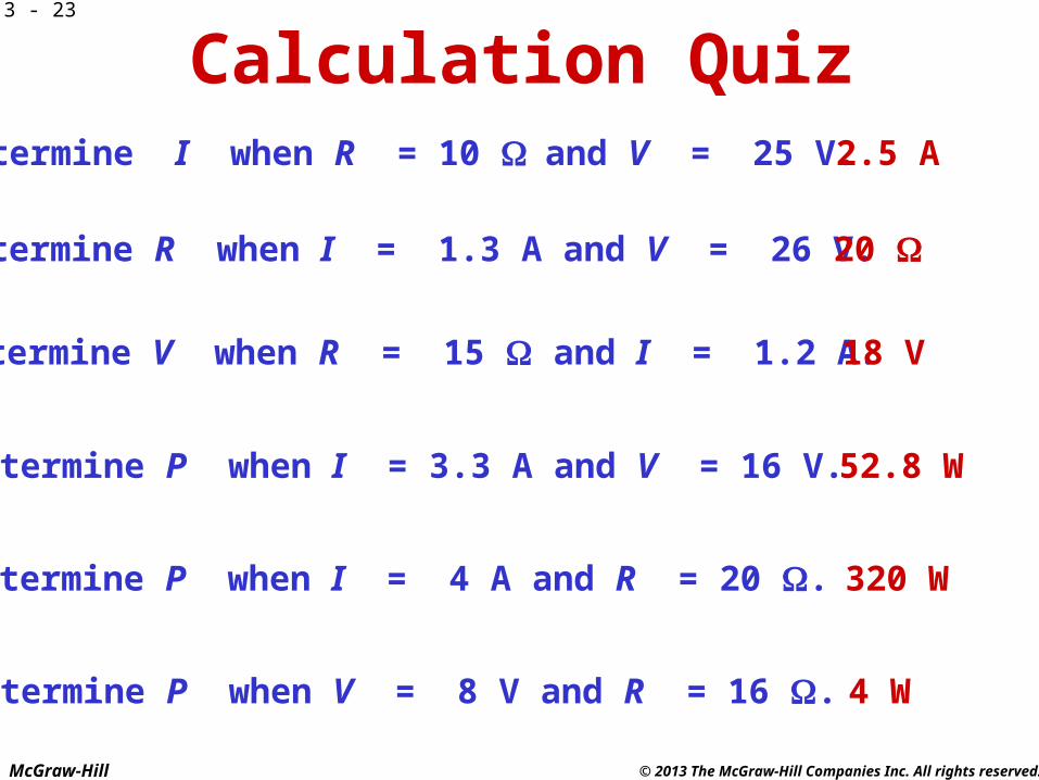
Calculation QuizDetermine I when R = 10 and V = 25 V.
Determine R when I = 1.3 A and V = 26 V.
Determine V when R = 15 and I = 1.2 A.
Determine P when I = 3.3 A and V = 16 V.
Determine P when I = 4 A and R = 20 .
Determine P when V = 8 V and R = 16 .
2.5 A
20
18 V
52.8 W
320 W
4 W
3 - 23

McGraw-Hill © 2013 The McGraw-Hill Companies Inc. All rights reserved.
Concept Review• Ohm’s law states that I = V/R.
• Rearrangement can yield V = IR.
• Rearrangement also yields R = V/I.
• Any of three formulae can be used to calculate power.
Repeat Segment
3 - 24

McGraw-Hill © 2013 The McGraw-Hill Companies Inc. All rights reserved.
REVIEW• Circuit Symbols• Circuit Diagrams• Parts of a Circuit• Measuring Electrical Quantities• Calculating Electrical Quantities
3 - 25