Embed Size (px)
Citation preview

McGraw-Hill ©The McGraw-Hill Companies, Inc., 2004
Chapter 14
Local Area Networks:Ethernet

McGraw-Hill ©The McGraw-Hill Companies, Inc., 2004
Figure 14.1 Three generations of Ethernet

McGraw-Hill ©The McGraw-Hill Companies, Inc., 2004
PLS sublayer: encodes and decodes data [using manchester encoding].
AUI: Medium independent interface between PLS and MAU.
MAU (Transceiver): Medium-dependent. It’s a transmitter and receiver; it can detect collisions; Can be internal or external.
MDI (Medium Dependent Interface): Used to connect the transceiver to the medium. Just a connector like jack or tap.

McGraw-Hill ©The McGraw-Hill Companies, Inc., 2004
Figure 14.2 802.3 MAC frame
Data link layer is divided into logical link control (LLC) sublayer and medium access control (MAC) sublayer.
MAC Sublayer Access Method: CSMA/CD Frame contains destination and source physical address.
No Acknowledging procedure and thus known as unreliable. Preamble: Alternating 0s and 1s; used for synchronizing; 7bytes
(56 bits). Start Frame Delimiter (SFD): 10101011 indicates the start of the
frame. Last two bits alerts that the next field is destination address.
Length/Type: if less than 1518, it indicates the length of data field. If greater than 1536, it indicates the type of PDU.
Data: 46 to 1500 bytes; CRC: CRC-32

McGraw-Hill ©The McGraw-Hill Companies, Inc., 2004
Figure 14.3 Minimum and maximum length
Minimum length restriction because: Collision must be before a physical layer sends a frame out
of the station. If the entire frame is sent out before a collision is detected,
it is too late. The MAC layer has already discarded the frame, thinking that the frame has reached the destination.
Maximum length restriction is historical.

McGraw-Hill ©The McGraw-Hill Companies, Inc., 2004
Figure 14.4 Ethernet addresses in hexadecimal notation
Each station has a network interface card (NIC) Physical address: 6-byte [48 bits] It is written in hexadecimal notation using a
hyphen to separate bytes from each other.
Source address is always a unicast address – frame from only on station.
Destination address can be unicast [one to one] or multicast [a group of people] or broadcast [all members of the network].

McGraw-Hill ©The McGraw-Hill Companies, Inc., 2004

McGraw-Hill ©The McGraw-Hill Companies, Inc., 2004
Figure 14.11 Connection of a station to the medium using 10Base5
Transceiver (Medium attachment Unit): Medium-independent. It creates the appropriate signal for each particular medium. There is a MAU for each type of medium used in 10-Mbps Ethernet.
Transceiver is a transmitter and receiver. It transmits signals over the medium; it receives signals over the medium; it also detects collisions.
10Base5 is called as Thick Ethernet or Thicknet; Uses coaxial cable.
Uses Bus topology. Transceiver cable is called as Attachment unit interface
(AUI) cable.

McGraw-Hill ©The McGraw-Hill Companies, Inc., 2004
Figure 14.12 Connection of stations to the medium using 10Base2
Thin Ethernet or Cheapernet. Uses Bus topology with an internal transceiver
or a point-to-point connection via an external transceiver.
Internal transceiver does not need AUI cable.

McGraw-Hill ©The McGraw-Hill Companies, Inc., 2004
Figure 14.13 Connection of stations to the medium using 10Base-T
Twisted-pair Ethernet. Physical star topology Stations are connected to a hub with an
internal transceiver or an external transceiver.

McGraw-Hill ©The McGraw-Hill Companies, Inc., 2004
Figure 14.14 Connection of stations to the medium using 10Base-FL
Fiber Link Ethernet. Uses star topology to connect stations to a hub Normally an external transceiver called fiber-
optic MAU is used. Transceiver is connected to the hub by using
two pairs of fiber-optic cables.

McGraw-Hill ©The McGraw-Hill Companies, Inc., 2004
Figure 14.15 Sharing bandwidth
Without bridges, all the stations share the bandwidth of the network.
Bridges divide the network into two. Bandwithwise, each network is independent.
With bridges, 10 Mbps network is shared only by 6 [actually 7 as bridge acts as one station]stations.

McGraw-Hill ©The McGraw-Hill Companies, Inc., 2004
Figure 14.17 Collision domains in a nonbridged and bridged network
Using bridges, collision domain becomes much smaller and the probability of collision is reduced tremendously.
McGraw-Hill ©The McGraw-Hill Companies, Inc., 2004
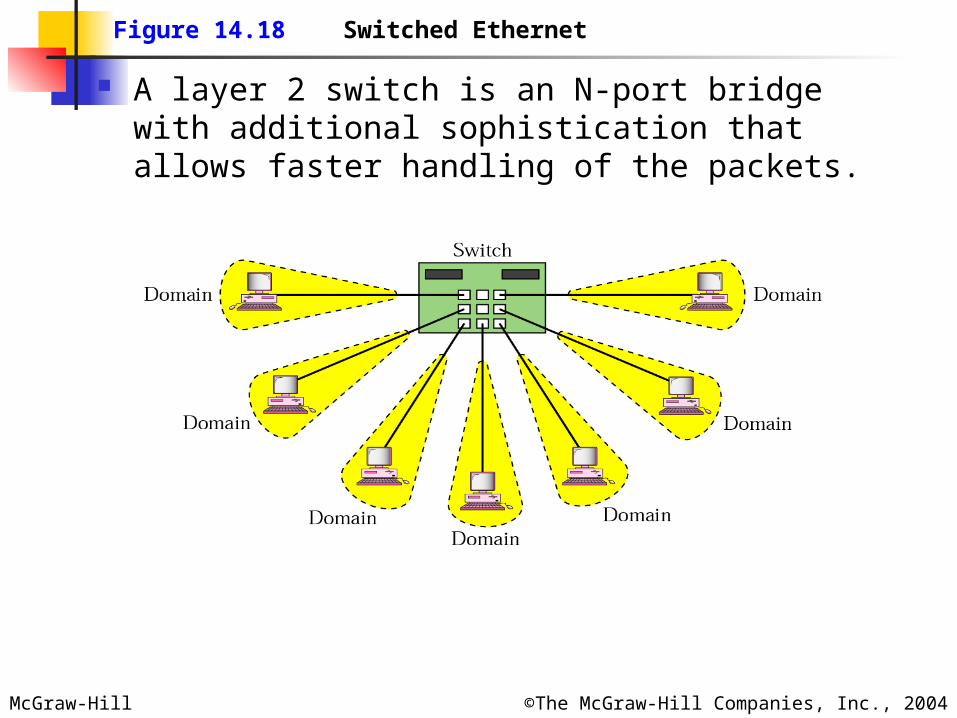
Figure 14.18 Switched Ethernet
A layer 2 switch is an N-port bridge with additional sophistication that allows faster handling of the packets.

McGraw-Hill ©The McGraw-Hill Companies, Inc., 2004
Figure 14.19 Full-duplex switched Ethernet
As there are two links, one each for sending and receiving, we don’t need CSMA/CD here.
No flow or error control here. Flow and error control is provided by a new
sublayer, called the MAC control, which is added between the LLC and MAC sublayer.

McGraw-Hill ©The McGraw-Hill Companies, Inc., 2004
Figure 14.20 Fast Ethernet physical layer
Autonegotiation: Allows two devices to negotiate the mode or data rate of operation.
Transceiver [PHY sublayer] does the job of encoding and decoding.
RS looks at passing data as 4-bit nibbles to MII. MII = AUI; Supports both 10 and 100 Mbps; Has
4 bits parallel path; Management functions are added.

McGraw-Hill ©The McGraw-Hill Companies, Inc., 2004
Figure 14.22 Fast Ethernet implementations
Two wire or four wire. Two wire: 100Base-X: With twisted pair
(100Base-TX) or Fiber optic (100Base-FX) Four wire: Twisted pair (100BaseT4)

McGraw-Hill ©The McGraw-Hill Companies, Inc., 2004
Figure 14.23 100Base-TX implementation
Internal or external transceiver. Uses 4B/5B for synchronization.

McGraw-Hill ©The McGraw-Hill Companies, Inc., 2004
Figure 14.25 100Base-FX implementation
Uses two pairs of fiber-optic cables in a physical star topology.

McGraw-Hill ©The McGraw-Hill Companies, Inc., 2004
Figure 14.27 100Base-T4 implementation
100Base-TX Can provide data rate of 100Mbps, but it requires the use of category 5 UTP or STP cable.
100Base-T4 was designed to use CAT-3 [voice-grade twisted pair] or higher UTP. Implementation uses four pairs of UTP for transmitting 100 Mbps.

McGraw-Hill ©The McGraw-Hill Companies, Inc., 2004
Figure 14.28 Using four wires in 100Base-T4
To cut down the number of pairs to four, two pairs are designed for unidirectional transmission and the other two for bidirectional transmission.
The two unidirectional pairs are always free in one direction to carry collision signals.

McGraw-Hill ©The McGraw-Hill Companies, Inc., 2004
Figure 14.29 Physical layer in Gigabit Ethernet
RS sends 8-bit parallel data to PHY via GMII. GMII is a logical interface and not physical.
Operates at 1000 Mbps, Has Management functions. There is no GMII cable or connector.
PHY: There is no external transceiver. MDI: Connects transceiver to the medium. For
Gigabit Ethernet, only the RJ-45 and fiber-optic connectors are defined.

McGraw-Hill ©The McGraw-Hill Companies, Inc., 2004
Figure 14.30 Gigabit Ethernet implementations
Access: Half-duplex using CSMA/CD or Full-duplex with no need for CSMA/CD
1000Base-X: Two wire implementation Short wave optical fiber (1000Base-SX) Long wave optical fiber (1000Base-LX) Short copper jumpers (1000Base-CX) using
STP. 1000Base-T: Four-wire version using twisted-pair
cable [UTP].

McGraw-Hill ©The McGraw-Hill Companies, Inc., 2004
Figure 14.31 1000Base-X implementation
Both 1000Base-SX and 1000Base-LX use two fiber-optic cables.
Transceiver in all implementations are internal Uses 8B/10B for synchronization.

McGraw-Hill ©The McGraw-Hill Companies, Inc., 2004
Figure 14.33 1000Base-T implementation
Designed to use Category 5 UTP. Four twisted pairs achieve a transmission rate of 1
Gbps. To send 1.25Gbps over four pairs of UTP, 1000Base-T
uses an encoding scheme called 4D-PAM5 (4-dimensional, 5-level pulse amplitude modulation).
Five levels of pulse amplitude modulation are used.