Embed Size (px)
Citation preview
AMD HD5450
PCIe® ADD-IN BOARD
Datasheet AEGX-A3T5-01FST1

REV 0.3 Page 2 of 18 Sep. 16, 2015
CONTENTS
1. Feature .................................................................................................................. 3
2. Functional Overview ............................................................................................. 4
2.1. Memory Interface ..................................................................................... 4
2.2. Acceleration Features ............................................................................... 4
2.3. Avivo™ Display System .............................................................................. 5
2.4. DVI/HDMI Features ................................................................................... 6
2.5. DisplayPort Features ................................................................................. 6
2.6. Integrated HD-Audio Controller (Azalia) and Codec ................................. 7
2.7. Dual Analog-Out Feature .......................................................................... 7
2.7.1. Dual DACs ............................................................................................................. 7
2.8. Bus Support Features ................................................................................ 8
3. PIN Assignment and Description ........................................................................... 9
4. Power Consumption ............................................................................................ 13
5. Output configuration and Board Dimension ....................................................... 14
5.1. Output Configuration .............................................................................. 14
5.2 Board Dimension ........................................................................................... 15
6. Thermal Mechanism............................................................................................ 16
7. Order Information ............................................................................................... 18
8. Change Log Update History ................................................................................. 18

REV 0.3 Page 3 of 18 Sep. 16, 2015
1. Feature
Model Name AEGX-A3T5-01FST1
Graphics Processing Unit
APU HD5450 ( Park LP)
Process Technology 40 nm
Graphics Engine Operating
Frequency (max) 650 GHz
Form Factor ATX (167 X 69 mm)
Card Interface PCI Express® 2.1 (X16)
Shader Processing Units 80 shaders
Floating Point Performance
(single precision, peak) 104 GFLOPs
DirectX® capability DirectX® 11
Shader Model Shader Model 5.0
OpenGL OpenGL™ 4.1
OpenCL™ OpenCL™ 1.1
Unified Video Decoder (UVD) UVD3 for H.264, VC-1, MPEG-2, MPEG-4 part 2
decode
Memory
Memory Operating Frequency
(max) 500 MHz / 1 Gbps
Configuration, type 64-bit wide, 1 GB, DDR3
Display Interface
Single / Dual-Link DVI Dual DVI-D X1
CRT 15-pin D-SUB X 1
HDMI HDMI X1

REV 0.3 Page 4 of 18 Sep. 16, 2015
2. Functional Overview
2.1. Memory Interface
Memory configuration support
The Cedar has two DRAM sequencers. Each DRAM channel is 32-bit wide. All DRAM devices must be
of the same type, have the same size on each channel, and must run at the same voltage.
Supported DRAM Component Organizations:
4, 8, or 16 banks (2-, 3-, or 4-bank bits). Single- or dual-rank.
Rows: 1024, 2048, 4096, 8192, or 16384 (10, 11, 12, 13, or 14 bits).
Columns: 256, 512, or 1024
CS (chip select):1 or 2
2.2. Acceleration Features
Fully DirectX® 11 compliant, including full-speed 32-bit floating point per
component operation:
Shader Model 5.0 geometry and pixel support in a unified-shader
architecture:
Vertex, pixel, geometry, compute, domain, and hull shaders.
32- and 64-bit floating-point processing per component.
High-performance dynamic branching and flow control.
Nearly unlimited shader-instruction store, using an advanced
caching system.
Advanced shader design, with ultra-threading sequencer for high efficiency
operations.
Advanced, high-performance branching support, including static
and dynamic branching.
High dynamic-range rendering with floating-point blending, texture
filtering and anti-aliasing support.
16- and 32-bit floating-point components for high dynamic-range
computations.
Full anti-aliasing on render surfaces up to and including 128-bit
floating-point formats.
Support for OpenGL 3.2.
REV 0.3 Page 5 of 18 Sep. 16, 2015
Support for OpenCL™ 1.0.
Anti-Aliasing Filtering:
2x/4x modes.
Multi- and super-sample algorithms with gamma correction,
programmable sample patterns, and centroid sampling.
Custom filter anti-aliasing with up to 12-samples per pixel.
Adaptive anti-aliasing mode.
Lossless color compression (up to 8:1) at all resolutions, up to and including
wide-screen HDTV.
Anisotropic Filtering:
2x/4x/8x/16x modes.
Up to 128-tap texture filtering.
Anisotropic biasing to allow trading quality for performance.
Improved quality mode due to improved sub-pixel precision and higher
precision LOD computations.
Advanced texture compression (3Dc+™ ).
High-quality 4:1 compression for normal and luminance maps.
Angle-invariant algorithm for improved quality.
Works with any single- or two-channel data format
Hardware support to overcome "small batch" issues in CPU limited applications.
3D resources virtualized to a 32-bit addressing space for support of large
numbers of render targets and textures.
Up to 16k × 16k textures, including 128-bit/pixel textures are supported.
Programmable arbitration logic maximizes memory efficiency and is software
upgradeable.
Fully associative texture, color, and z-cache design.
Hierarchical z- and stencil-buffers with early z-test.
Lossless z-buffer compression for both z and stencil.
Fast z-buffer clear.
Fast color-buffer clear.
Z cache optimized for real-time shadow rendering.
Z- and color-compression resources virtualized to a 32-bit addressing space, for
support of multiple render targets and textures simultaneously.
2.3. Avivo™ Display System
The AMD Avivo™ display system supports VGA, VESA super VGA, and accelerator
mode graphics display on three independent display controllers.
REV 0.3 Page 6 of 18 Sep. 16, 2015
The full features of the AMD Avivo display system are outlined in the following
sections.
2.4. DVI/HDMI Features
Advanced DVI capability supporting 10-bit HDR (high dynamic range) output.
Supports industry-standard CEA-861B video modes including 480p, 720p,
1080i, and 1080p. For a full list of currently supported modes, contact your local AMD
support person.
Maximum pixel rates for 24-bpp outputs are:
DVI — 162 MP/s (megapixels per second) per link for 30-bpp dual-link;
double for 24-bpp dual-link.
HDMI— 148.5 MP/s.
Fully compliant with the DVI electrical specification.
HDMI meets Windows Vista® logo requirements.
2.5. DisplayPort Features
Supports all the mandatory features of the DisplayPort Version 1.1a
Specification and the following optional features:
30-bit support.
YCbCr 444 up to 30-bpp and 422 up to 20-bpp support.
HDCP support.
DisplayPort extension for test-automation features, including test-pattern
generation.
DisplayPort Audio.
Each DisplayPort link can support three options for the number of lanes and two options
for link-data rate as follows:
Four, two, or one lane(s).
2.7- or 1.62-GHz link-data rate per lane.
Supports all video modes supported by the display controller that do not
oversubscribe the link bandwidth.
Examples of supported pixel-rate/resolution support for four lanes at 2.7-
GHz link rate:
Link bandwidth allows pixel clocks of up to 359 MP/s for 24 bpp or 287 MP/s for 30
bpp.
2560×1600@60Hz, 30 bpp is supported.
Examples of supported pixel-rate/resolution support for two lanes at 2.7- GHz link rate:

REV 0.3 Page 7 of 18 Sep. 16, 2015
Link bandwidth allows pixel clocks of up to 179 MP/s for 24 bpp or 143 MP/s for 30
bpp.
1920×1200@60Hz, 24 bpp is supported.
The following table shows the maximum pixel rates for four, two, or one lane(s) at
2.7-GHz link rate
2.6. Integrated HD-Audio Controller (Azalia) and Codec
The integrated HD-Audio codec supports linear PCM and Dolby Digital (7.1) audio formats
for HDMI and DisplayPort outputs.
Note: Player applications may limit audio output capabilities.
Separate logical-chip function.
Can encrypt data onto one associated HDMI output.
Compatible Microsoft® UAA driver support for basic audio.
For advanced functionality, a 3rd party driver is required.
Internally connected to the integrated HDMI interface, hence no external cable is
required.
Supports Dolby True HD, DTS-HD, Dolby Digital (AC3), and DTS.
LPCM and high-bit rate audio support — up to 24 bits/sample and up to 192-kHz
sampling rate.
Support for up to eight channels.
HDCP content-protection support for software-audio stack.
True audio plug-and-play capability for enhanced-audio modes.
Audio DRM supported.
2.7. Dual Analog-Out Feature
2.7.1. Dual DACs
Two integrated triple 10-bit DACs with a built-in reference circuit, which takes the output
from either one of the internal display controllers (primary or secondary) or the internal

REV 0.3 Page 8 of 18 Sep. 16, 2015
analog-TV encoder.
Dual RGB-CRT output.
Support for the stereo-sync signal to drive a 3D display.
Maximum pixel frequency of 400 MHz.
Individual power-down feature for each of the three guns.
Fully compliant with the VSIS electrical specification.
Fully integrated with built-in band gap reference circuitry.
Optional dynamic monitor detection for hot-plug/unplug capability. This feature affects
the DAC-voltage ranges. Please check with AMD for details before enabling.
Integrated monitor- and TV-detection circuit (TV detection for DAC2 only).
Internal demultiplexer in DAC2, allowing it to be output on one of the two output signal
groups (TV or CRT), which allows separate external output filters without an external
multiplexer. See the following section for TV-out features.
2.8. Bus Support Features
Fully compliant with PCI Express® Base Specification Revision 2.1 PCIe® bus interface.
Supports x1, x2, x4, x8, and x16 lane widths.
Supports 2.5 GT/s and 5.0 GT/s link-data rates.
Supports x16 lane reversal where the receiver on lanes 0 to 15 on the graphics endpoint
are mapped to the transmitter on lanes 15 down to 0 on the root complex.
Supports x16 lane reversal where the transmitter on lanes 0 to 15 on the graphics
endpoint are mapped to the receiver on lanes 15 down to 0 on the root complex (requires
corresponding support on the root complex).
Supports full-swing and low-swing transmitter output levels.

REV 0.3 Page 9 of 18 Sep. 16, 2015
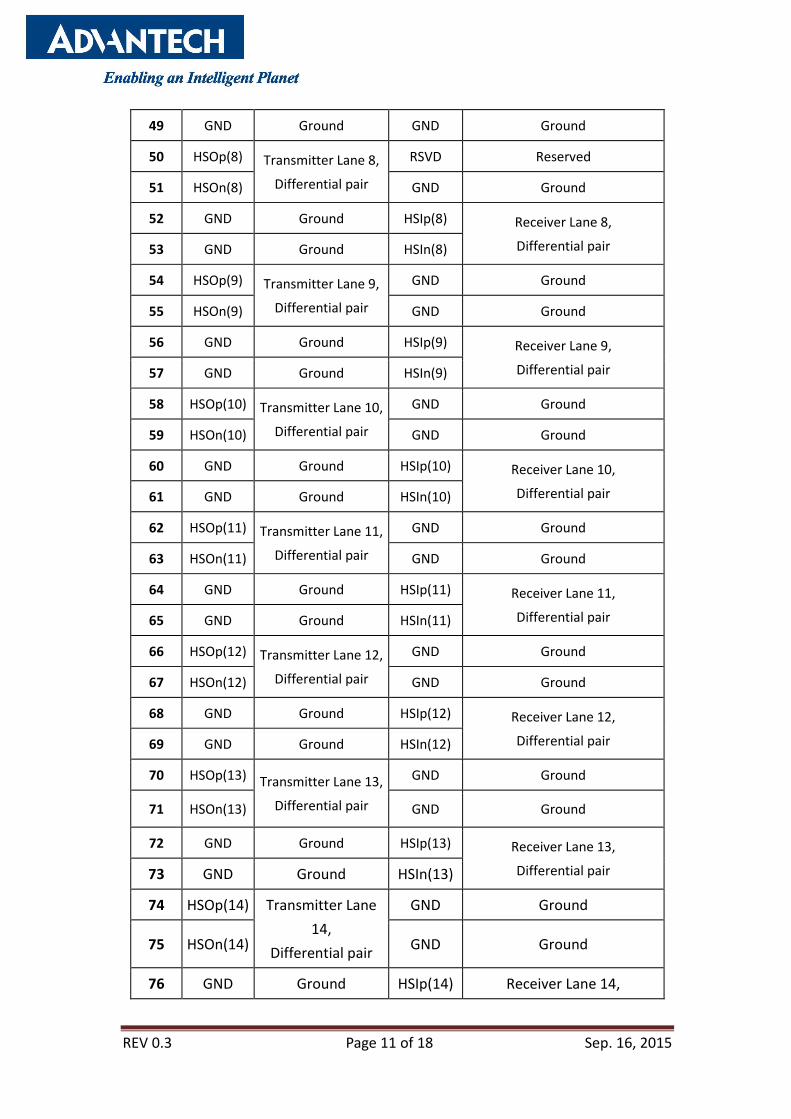
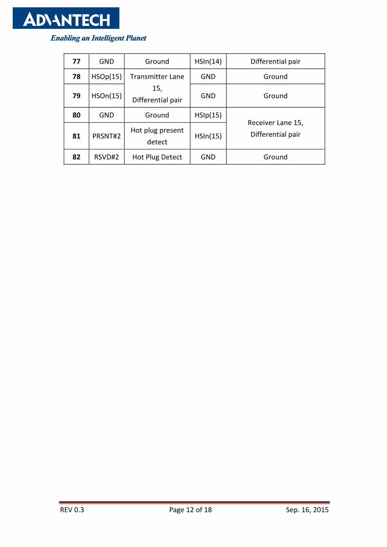
3. PIN Assignment and Description
Pin Side B Connector Side A Connector
# Name Description Name Description
1 +12v +12 volt power PRSNT#1 Hot plug presence detect
2 +12v +12 volt power +12v +12 volt power
3 RSVD Reserved +12v +12 volt power
4 GND Ground GND Ground
5 SMCLK SMBus clock JTAG2 TCK
6 SMDAT SMBus data JTAG3 TDI
7 GND Ground JTAG4 TDO
8 +3.3v +3.3 volt power JTAG5 TMS
9 JTAG1 +TRST# +3.3v +3.3 volt power
10 3.3Vaux 3.3v volt power +3.3v +3.3 volt power
11 WAKE# Link Reactivation PWRGD Power Good
Mechanical Key
12 RSVD Reserved GND Ground
13 GND Ground REFCLK+ Reference Clock
Differential pair 14 HSOp(0) Transmitter Lane
0,
Differential pair
REFCLK-
15 HSOn(0) GND Ground
16 GND Ground HSIp(0) Receiver Lane 0,
Differential pair 17 PRSNT#2 Hotplug detect HSIn(0)
18 GND Ground GND Ground
19 HSOp(1) Transmitter Lane
1,
Differential pair
RSVD Reserved
20 HSOn(1) GND Ground
21 GND Ground HSIp(1) Receiver Lane 1,
Differential pair 22 GND Ground HSIn(1)

REV 0.3 Page 10 of 18 Sep. 16, 2015
23 HSOp(2) Transmitter Lane
2,
Differential pair
GND Ground
24 HSOn(2) GND Ground
25 GND Ground HSIp(2) Receiver Lane 2,
Differential pair 26 GND Ground HSIn(2)
27 HSOp(3) Transmitter Lane
3,
Differential pair
GND Ground
28 HSOn(3) GND Ground
29 GND Ground HSIp(3) Receiver Lane 3,
Differential pair 30 RSVD Reserved HSIn(3)
31 PRSNT#2 Hot plug detect GND Ground
32 GND Ground RSVD Reserved
33 HSOp(4) Transmitter Lane
4,
Differential pair
RSVD Reserved
34 HSOn(4) GND Ground
35 GND Ground HSIp(4) Receiver Lane 4,
Differential pair 36 GND Ground HSIn(4)
37 HSOp(5) Transmitter Lane
5,
Differential pair
GND Ground
38 HSOn(5) GND Ground
39 GND Ground HSIp(5) Receiver Lane 5,
Differential pair 40 GND Ground HSIn(5)
41 HSOp(6) Transmitter Lane
6,
Differential pair
GND Ground
42 HSOn(6) GND Ground
43 GND Ground HSIp(6) Receiver Lane 6,
Differential pair 44 GND Ground HSIn(6)
45 HSOp(7) Transmitter Lane
7,
Differential pair
GND Ground
46 HSOn(7) GND Ground
47 GND Ground HSIp(7) Receiver Lane 7,
Differential pair 48 PRSNT#2 Hot plug detect HSIn(7)
REV 0.3 Page 11 of 18 Sep. 16, 2015
49 GND Ground GND Ground
50 HSOp(8) Transmitter Lane 8,
Differential pair
RSVD Reserved
51 HSOn(8) GND Ground
52 GND Ground HSIp(8) Receiver Lane 8,
Differential pair 53 GND Ground HSIn(8)
54 HSOp(9) Transmitter Lane 9,
Differential pair
GND Ground
55 HSOn(9) GND Ground
56 GND Ground HSIp(9) Receiver Lane 9,
Differential pair 57 GND Ground HSIn(9)
58 HSOp(10) Transmitter Lane 10,
Differential pair
GND Ground
59 HSOn(10) GND Ground
60 GND Ground HSIp(10) Receiver Lane 10,
Differential pair 61 GND Ground HSIn(10)
62 HSOp(11) Transmitter Lane 11,
Differential pair
GND Ground
63 HSOn(11) GND Ground
64 GND Ground HSIp(11) Receiver Lane 11,
Differential pair 65 GND Ground HSIn(11)
66 HSOp(12) Transmitter Lane 12,
Differential pair
GND Ground
67 HSOn(12) GND Ground
68 GND Ground HSIp(12) Receiver Lane 12,
Differential pair 69 GND Ground HSIn(12)
70 HSOp(13) Transmitter Lane 13,
Differential pair
GND Ground
71 HSOn(13) GND Ground
72 GND Ground HSIp(13) Receiver Lane 13,
Differential pair 73 GND Ground HSIn(13)
74 HSOp(14) Transmitter Lane
14,
Differential pair
GND Ground
75 HSOn(14) GND Ground
76 GND Ground HSIp(14) Receiver Lane 14,
REV 0.3 Page 12 of 18 Sep. 16, 2015
77 GND Ground HSIn(14) Differential pair
78 HSOp(15) Transmitter Lane
15,
Differential pair
GND Ground
79 HSOn(15) GND Ground
80 GND Ground HSIp(15) Receiver Lane 15,
Differential pair 81 PRSNT#2 Hot plug present
detect HSIn(15)
82 RSVD#2 Hot Plug Detect GND Ground

REV 0.3 Page 13 of 18 Sep. 16, 2015
4. Power Consumption
Application Total ASIC Power + DRAM Power (W)
Static Windows 4.23
Application Total ASIC Power + DRAM Power (W)
3D Mark 2003 20.86
REV 0.3 Page 14 of 18 Sep. 16, 2015
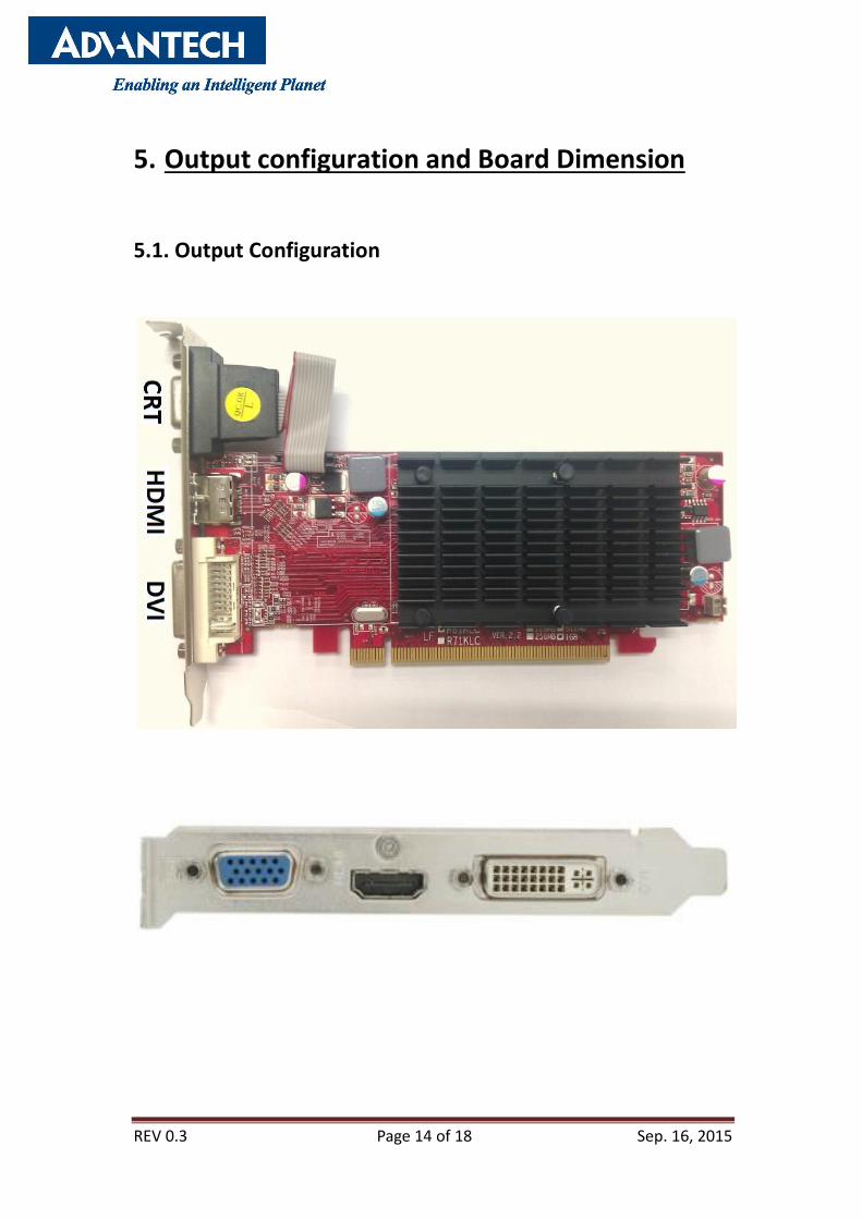
5. Output configuration and Board Dimension
5.1. Output Configuration
REV 0.3 Page 15 of 18 Sep. 16, 2015
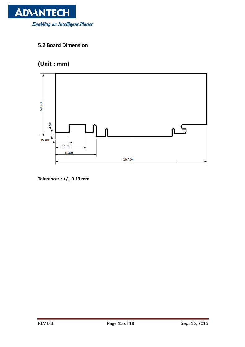
5.2 Board Dimension
(Unit : mm)
Tolerances : +/_ 0.13 mm
REV 0.3 Page 16 of 18 Sep. 16, 2015
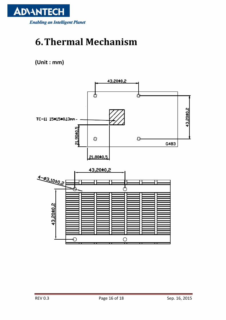
6. Thermal Mechanism
(Unit : mm)

REV 0.3 Page 17 of 18 Sep. 16, 2015

REV 0.3 Page 18 of 18 Sep. 16, 2015
7 Order Information
8 Change Log Update History
Rev. Data History
0.1 2012/8/10 1st Draft
0.2 2012/11/6 Modify page 14, output port on bracket picture, DVI-D to
DVI-I.
0.3 2015/09/16 Modify P/N from GFX-A3T5-01FST1 to AEGX-A3T5-01FST1
Add Item 7:Order Information
Model GPU Form Factor Memory DVI-D HDMI VGA Bracket Thermal
Solution Remark
AEGX-A3T5-01FST1 HD5450 ATX (167 X 69 mm) 64-bit wide, 1 GB, DDR3 1 1 1 Full Height /
Low Profile Fanless PCI-E 16X