Embed Size (px)
Citation preview
1
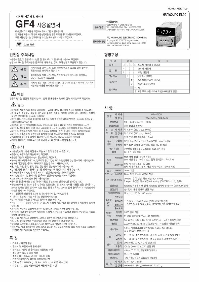
형 명지 시 용 GF4-T40N
설 정 용 GF4-P41N / GF4-P41S
전원전압 100 - 240 V a.c. 50 - 60 ㎐
전압변동율 전원 전압의 ±10 %
소 비 전 력
지 시 용 약 4.3 VA (220 V a.c. 60 ㎐)
설 정 용 약 6.2 VA (220 V a.c. 60 ㎐)
표시방식 적색 FND 4행 (문자높이 : 8 ㎜)
제어출력
유접점 SPDT (1c), 250 V a.c. 3 A 저항부하, cosØ = 0.4
무접점 NPN 오픈 콜렉터, 30 V d.c. max, 100 ㎃ max
ONE SHOT출력
전면부의 TM 볼륨을 사용하여 출력 시간 조정 (0.1 s ~ 12.5 sec)
입력방식
전압입력High 레벨 전압 : 5-30 V d.c.Low 레벨 전압 : 0-2 V d.c., 입력 임피던스 : 약 4.7 ㏀
무전압입력단락 시 임피던스 : 1 ㏀ 이하단락 시 잔류전압 : 2 V, 개방 시 임피던스 : 100 ㏀ 이상
최소입력시간
RESET 20 ㎳ 이상
INHIBIT 20 ㎳ 이상 (타이머 사용시 적용)
CP1,CP2 계수속도30 cps : 유/무접점, 최소 시간 16.7 ㎳ 이상 5 kcps : 무접점, 최소 시간 0.1 ㎳ 이상 (ON/OFF = 1:1 인 경우)
정전보상 정전보상 / 전원 리셋 선택, 정전보상 선택시 반 영구적 (EEPROM 방식)
설정방식 상시인식 (통전 중에도 변경 가능)
외부공급전원 12 V d.c. ±10 %, 100 ㎃ max
타이머동작오차
반복오차
± 0.01 % ± 0.05 초 이하 (전원 START인 경우)± 0.005 % ± 0.003 초 이하 (RESET에 의한 START인 경우)
설정오차
전압오차
온도오차
릴레이수명
기계적 1,000 만회 이상
전기적 10 만회 이상 (250 V a.c. 3A 저항부하)
절연저항 100 ㏁ 이상 (500 V d.c. 메가로 도전부단자 - 노출된 비충전 금속)
내전압 2,000 V a.c. 60 ㎐ 1분간 (도전부 단자 - 노출된 비충전 금속)
내노이즈노이즈 시뮬레이터에 의한 방형파 노이즈 (1㎲ 펄스폭), ± 2 ㎸ (조작 전원 단자 간)
진동내진동 10 - 55 ㎐ (주기 1분간) 복진폭 0.75 ㎜ X, Y, Z 각 방향 1시간
오동작 10 - 55 ㎐ (주기 1분간) 복진폭 0.5 ㎜ X, Y, Z각 방향 10분간
충격내충격 300 ㎨ (30 G) X, Y, Z 각 방향 3회
오동작 100 ㎨ (10 G) X, Y, Z 각 방향 3회
사용주위온도 -10 ~ 55 ℃ (단, 결빙되지 않을것.)
사용주위습도 35 ~ 85 % R.H
보관온도 -20 ~ 65 ℃ (단, 결빙되지 않을것.)
중 량지 시 용 GF4-T40N : 168 g
설 정 용 GF4-P41N : 184 g, GF4-P41S : 약 100 g
•사용설명서의 내용은 사전 통보 또는 예고 없이 변경될 수 있습니다.
•주문하신 사양과 일치하는지 확인 하십시오.
•운송중 파손 및 제품에 이상이 없는지 확인 하십시오.
•부식성 가스 (특히 유해가스, 암모니아 등), 가연성 가스가 발생하지 않는 장소에서 사용하십시오.
•본체에 직접 진동, 충격이 가하여지지 않는 장소에서 사용하십시오.
•물, 기름, 약품, 증기, 먼지, 염분, 철분 등이 없는 장소에서 사용하십시오.
•알코올, 벤젠 등 유기 용재로 본기를 닦지 마십시오. (중성세제로 닦아 주십시오.)
•유도장애가 크고 정전기, 자기 노이즈가 발생하는 장소는 피하여 주십시오.
•직사일광 및 복사열 등에 의한 열 축적이 발생하는 장소는 피하여 주십시오.
•고도 2,000m이하의 장소에서 사용하십시오.
•물이 들어갔을 때에는 누전, 화재의 위험성이 있으므로 필히 점검을 받아주십시오.
• 전원으로부터 노이즈가 많은 경우에는 절연트랜스 및 노이즈 필터를 사용할 것을 장려합니다.
노이즈 필터는 필히 접지되어 있는 판넬 등에 부착하고 노이즈 필터 출력측과 계기전원단자의
배선은 짧게 하여 주십시오.
•계기 전원선은 촘촘하게 꼬으면 노이즈에 대하여 효과가 있습니다.
•사용하지 않는 단자에는 아무것도 결선하지 마십시오.
•단자의 극성을 확인한 후 배선을 정확하게 연결 바랍니다.
• 작업자가 즉시 전원을 OFF할 수 있도록 스위치 혹은 차단기를 설치하여 적절하게 표시해
주십시오.
•스위치나 차단기는 운전자가 조작이 용이하도록 가까운 거리에 설치 하십시오.
• 스위치나 차단기가 설치되어 있으므로 스위치나 차단기를 작동하면 전원이 차단된다는 사항을
판넬에 명기하십시오.
•본기기를 계속적으로 안전하게 사용하기 위하여 정기적인 보수를 권장합니다.
•본기기의 탑재부품에는 수명이 있는 것과 경년 변화 하는 것이 있습니다.
•부속품을 포함한 본기기의 보증기간은 정상적으로 사용한 경우에 1년입니다.
• 전원 투입 시에 접점출력의 준비기간이 필요합니다. 외부의 인터록 회로 등에 신호로 사용되는
경우에는 지연 릴레이를 병용하여 주십시오.
• 타이머 / 카운터 겸용
• 릴레이 및 트렌지스터 동시 출력
• 입력모드 14종류 및 출력 모드 16종류로 구성
• 최대 계수 속도 5 kcps 지원
• 출력의 ON-DELAY 및 OFF-DELAY 기능
• 전압 입력(PNP) 및 무전압 입력(NPN)선택
• 입력 신호의 RISING( )및 FALLING( )에 따른 계수 선택
• 소수점 위치 설정 기능 (카운터 사용시 적용, 고정)
MD0104KE171109
디지털카운터&타이머
GF4 사용설명서 (주)한영넉스의 제품을 구입하여 주셔서 대단히 감사합니다.
본 제품을 사용하시기 전에 사용설명서를 잘 읽은 후에 올바르게 사용해 주십시오.
또한, 사용설명서는 언제라도 볼 수 있는 곳에 반드시 보관해 주십시오.
•제조자가 지정한 방법 이외로 사용시에는 상해를 입거나 재산상의 손실이 발생할 수 있습니다.
• 본 제품의 고장이나 이상이 시스템에 중대한 사고로 이어질 우려가 있는 경우에는 외부에
적절한 보호회로를 설치하여 주십시오.
•본기기에는 전원 스위치 및 퓨즈가 부착되어 있지 않으므로 외부에 별도로 설치하여 주십시오.
(퓨즈정격:250 V 0.5 A)
•감전방지 및 기기고장방지를 위하여 모든 배선이 종료될 때까지 전원을 투입하지 마십시오.
•본기기는 절대로 분해, 가공, 개선, 수리하지 마십시오. 이상동작, 감전화재의 위험이 있습니다.
•본기기의 탈착은 전원을 OFF한 후 조치하여 주십시오. 감전, 오 동작, 고장의 원인이 됩니다.
•본기기의 파손방지 및 고장방지를 위하여 정격에 맞는 전원전압을 공급하여 주십시오.
•방폭구조가 아니므로 가연성, 폭발성 가스가 있는 장소에서는 사용하지 마십시오.
•감전될 위험이 있으므로 본기기를 패널에 설치된 상태로 사용하여 주십시오.
입출력 단자는 감전의 위험이 있으니 신체 및 통전물이 절대로 접촉 되지 않도록 하십시오.
위 험
경 고
주 의
사양
특징
형명구성
형 명 코 드 내 용
GF4 - ☐ ☐ ☐ ☐ 디지털 카운터 & 타이머
종 류P 프리셋 카운터
T 토털 카운터
표시행수 4 4행표시 (9999)
설정단수1 1단 설정 (프리셋 카운터)
0 없음 (토털 카운터)
단자구조N 단자
S 8핀 구조 (8핀 소켓에 적합) (프리셋에 한함)
지키지 않을 경우, 사망 또는 중상에 이르는 결과를 낳는 절박한 위험 상황을 표시하고 있습니다.
지키지 않을 경우, 사망 또는 중상이 발생할 가능성이 예상되는 내용을 표시하고 있습니다.
지키지 않을 경우, 경미한 상해나 재산상의 손해가 발생할 가능성이 예상되는 내용을 표시하고 있습니다.
안전상주의사항사용전에 안전에 관한 주의사항을 잘 읽어 주시고 올바르게 사용하여 주십시요.
설명서에 표시된 주의사항은 중요도에 따라 위험, 경고, 주의 심벌로 구분하고 있습니다.
위험
경고
주의
인천광역시 남구 길파로71번길 28 TEL : (032)867-0941 FAX : (032)868-5899고객지원센터 1577-1047 http://www.hynux.com
(주)한영넉스
본사/공장
Jl. Jangari RT.003/002 HegarmanahSukaluyu Cianjur Jawa Barat Indonesia 43284TEL : +62-2140001930
PT. HANYOUNG ELECTRONIC INDONESIA
인도네시아공장
2
6
ON
OFF
5 4 3 2 1 6 5 4 3 2 1
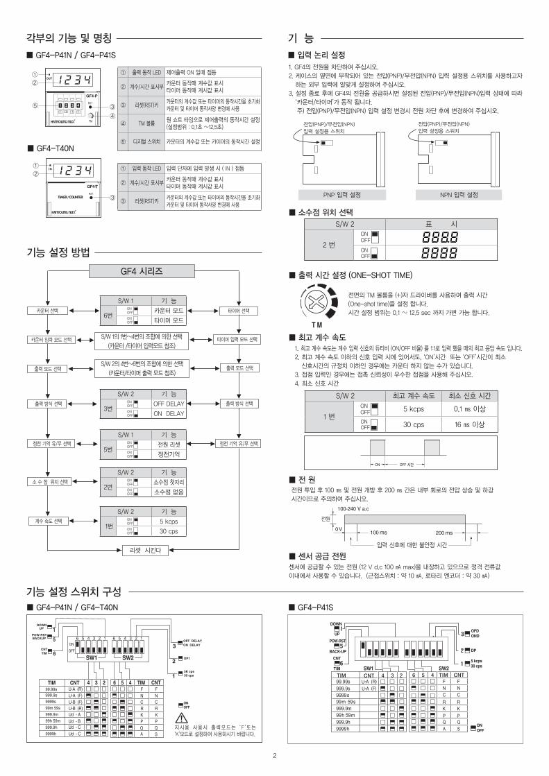
1. GF4의 전원을 차단하여 주십시오.
2. 케이스의 옆면에 부착되어 있는 전압(PNP)/무전압(NPN) 입력 설정용 스위치를 사용하고자
하는 외부 입력에 알맞게 설정하여 주십시오.
3. 설정 종료 후에 GF4의 전원을 공급하시면 설정된 전압(PNP)/무전압(NPN)입력 상태에 따라
‘카운터/타이머’가 동작 됩니다.
주) 전압(PNP)/무전압(NPN) 입력 설정 변경시 전원 차단 후에 변경하여 주십시오.
▒GF4-P41N/GF4-P41S
▒GF4-T40N
T
①
②
③
T
①
②
⑤ ③
④전압(PNP)/무전압(NPN)
입력 설정용 스위치
전압(PNP)/무전압(NPN)
입력 설정용 스위치
전압(PNP)/무전압(NPN)
입력 설정용 스위치
전압(PNP)/무전압(NPN)
입력 설정용 스위치
PNP 입력 설정 NPN 입력 설정
▒소수점위치선택
S/W 2 표 시
2 번
S/W 2 최고 계수 속도 최소 신호 시간
1 번5 kcps 0.1 ㎳ 이상
30 cps 16 ㎳ 이상
전면의 TM 볼륨을 (+)자 드라이버를 사용하여 출력 시간
(One-shot time)을 설정 합니다.
시간 설정 범위는 0.1 ~ 12.5 sec 까지 가변 가능 합니다.
▒출력시간설정(ONE-SHOTTIME)
▒최고계수속도 1. 최고 계수 속도는 계수 입력 신호의 듀티비 (ON/OFF 비율) 를 1:1로 입력 했을 때의 최고 응답 속도 입니다.
2. 최고 계수 속도 이하의 신호 입력 시에 있어서도, ‘ON’시간 또는 ‘OFF’시간이 최소
신호시간의 규정치 이하인 경우에는 카운터 하지 않는 수가 있습니다.
3. 접점 입력인 경우에는 접촉 신뢰성이 우수한 접점을 사용해 주십시오.
4. 최소 신호 시간
전원 투입 후 100 ㎳ 및 전원 개방 후 200 ㎳ 간은 내부 회로의 전압 상승 및 하강
시간이므로 주의하여 주십시오.
센서에 공급할 수 있는 전원 (12 V d.c 100 ㎃ max)을 내장하고 있으므로 정격 전류값
이내에서 사용할 수 있습니다. (근접스위치 : 약 10 ㎃, 로타리 엔코더 : 약 30 ㎃)
▒전원
▒센서공급전원
기능각부의기능및명칭
▒입력논리설정
① 출력 동작 LED 제어출력 ON 일때 점등
② 계수/시간 표시부카운터 동작때 계수값 표시타이머 동작때 계시값 표시
③ 리셋(RST)키카운터의 계수값 또는 타이머의 동작시간을 초기화 카운터 및 타이머 동작사양 변경때 사용
④ TM 볼륨원 쇼트 타임으로 제어출력의 동작시간 설정(설정범위 : 0.1초 ~12.5초)
⑤ 디지털 스위치 카운터의 계수값 또는 카이머의 동작시간 설정
① 입력 동작 LED 입력 단자에 입력 발생 시 ( IN ) 점등
② 계수/시간 표시부카운터 동작때 계수값 표시타이머 동작때 계시값 표시
③ 리셋(RST)키카운터의 계수값 또는 타이머의 동작시간을 초기화 카운터 및 타이머 동작사양 변경때 사용
지시용 사용시 출력모드는 ‘ F ’또는 ‘K’모드로 설정하여 사용하시기 바랍니다.
6
ON
OFF
5 4 3 2 1 6 5 4 3 2 1
타이머 선택카운터 선택
출력 모드 선택
출력 방식 선택
소 수 점 위치 선택
계수 속도 선택
타이머 입력 모드 선택
출력 모드 선택
출력 방식 선택
정전 기억 유/무 선택
S/W 1의 1번~4번의 조합에 의한 선택
(카운터 /타이머 입력모드 참조)
S/W 2의 4번~6번의 조합에 의한 선택
(카운터/타이머 출력 모드 참조)
GF4시리즈
정전 기억 유/무 선택
리셋 시킨다
카운터 입력 모드 선택
S/W 2 기 능
1번5 kcps
30 cps
S/W 2 기 능
2번소수점 첫자리
소수점 없음
S/W 1 기 능
5번전원 리셋
정전기억
S/W 2 기 능
3번OFF DELAY
ON DELAY
S/W 1 기 능
6번카운터 모드
타이머 모드
기능설정스위치구성
기능설정방법
▒GF4-P41N/GF4-T40N ▒GF4-P41S
3
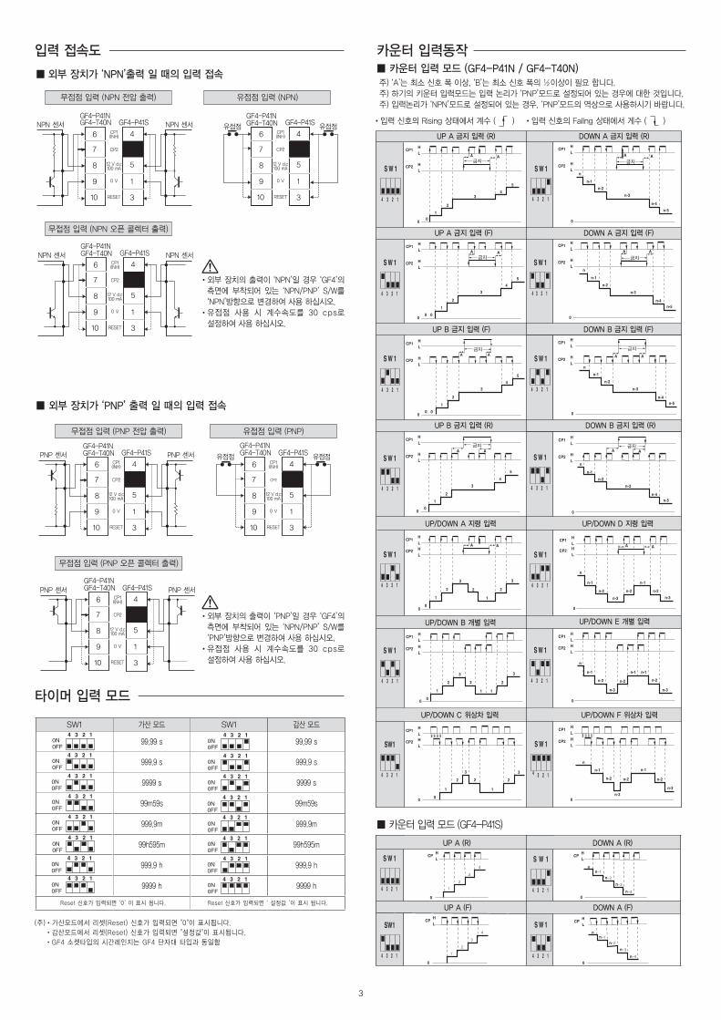
•입력 신호의 Rising 상태에서 계수 ( )
▒외부장치가‘NPN’출력일때의입력접속▒카운터입력모드(GF4-P41N/GF4-T40N)
▒외부장치가‘PNP’출력일때의입력접속
▒ 카운터 입력 모드 (GF4-P41S)
•입력 신호의 Fallng 상태에서 게수 ( )
주) ‘A’는 최소 신호 폭 이상, ‘B’는 최소 신호 폭의 ½이상이 필요 합니다.
주) 하기의 키운터 입력모드는 입력 논리가 ‘PNP’모드로 설정되어 있는 경우에 대한 것입니다.
주) 입력논리가 ‘NPN’모드로 설정되어 있는 경우, ‘PNP’모드의 역상으로 사용하시기 바랍니다.유접점 입력 (NPN)무접점 입력 (NPN 전압 출력)
무접점 입력 (NPN 오픈 콜렉터 출력)
6 4
5
1
3
7
8
9
10
6 4
5
1
3
7
8
9
10
6 4
5
1
3
7
8
9
10
6 4
5
1
3
7
8
9
10
6 4
5
1
3
7
8
9
10
6 4
5
1
3
7
8
9
10
윤고딕120 18P
유접점 입력 (PNP)
6 4
5
1
3
7
8
9
10
6 4
5
1
3
7
8
9
10
6 4
5
1
3
7
8
9
10
6 4
5
1
3
7
8
9
10
6 4
5
1
3
7
8
9
10
6 4
5
1
3
7
8
9
10
윤고딕120 18P
6 4
5
1
3
7
8
9
10
6 4
5
1
3
7
8
9
10
6 4
5
1
3
7
8
9
10
6 4
5
1
3
7
8
9
10
6 4
5
1
3
7
8
9
10
6 4
5
1
3
7
8
9
10
윤고딕120 18P
무접점 입력 (PNP 전압 출력)
6 4
5
1
3
7
8
9
10
6 4
5
1
3
7
8
9
10
6 4
5
1
3
7
8
9
10
6 4
5
1
3
7
8
9
10
6 4
5
1
3
7
8
9
10
6 4
5
1
3
7
8
9
10
윤고딕120 18P
6 4
5
1
3
7
8
9
10
6 4
5
1
3
7
8
9
10
6 4
5
1
3
7
8
9
10
6 4
5
1
3
7
8
9
10
6 4
5
1
3
7
8
9
10
6 4
5
1
3
7
8
9
10
윤고딕120 18P
무접점 입력 (PNP 오픈 콜렉터 출력)
6 4
5
1
3
7
8
9
10
6 4
5
1
3
7
8
9
10
6 4
5
1
3
7
8
9
10
6 4
5
1
3
7
8
9
10
6 4
5
1
3
7
8
9
10
6 4
5
1
3
7
8
9
10
윤고딕120 18P
• 외부 장치의 출력이 ‘NPN’일 경우 ‘GF4’의
측면에 부착되어 있는 ‘NPN/PNP’ S/W를
‘NPN’방향으로 변경하여 사용 하십시오.
• 유접점 사용 시 계수속도를 30 cps로
설정하여 사용 하십시오.
• 외부 장치의 출력이 ‘PNP’일 경우 ‘GF4’의
측면에 부착되어 있는 ‘NPN/PNP’ S/W를
‘PNP’방향으로 변경하여 사용 하십시오.
• 유접점 사용 시 계수속도를 30 cps로
설정하여 사용 하십시오.
입력접속도 카운터입력동작
타이머입력모드
(주)•가산모드에서 리셋(Reset) 신호가 입력되면 "0"이 표시됩니다.
•감산모드에서 리셋(Reset) 신호가 입력되면 "설정값"이 표시됩니다.
•GF4 소켓타입의 시간레인지는 GF4 단자대 타입과 동일함
SW1 가산 모드 SW1 감산 모드
99.99 s 99.99 s
999.9 s 999.9 s
9999 s 9999 s
99m59s 99m59s
999.9m 999.9m
99h595m 99h595m
999.9 h 999.9 h
9999 h 9999 h
Reset 신호가 입력되면 ‘0’ 이 표시 됩니다. Reset 신호가 입력되면 ‘ 설정값 ’이 표시 됩니다.
4
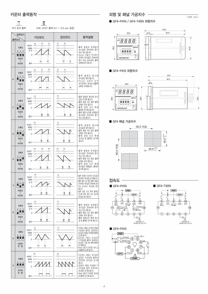
ONE-SHOT 출력 (0.1 ~ 12.5 sec 설정)자기 유지 출력
• 출 력 발 생 과 관 계 없 이 표시값은 연속하여 증가 또는 감소 됩니다.
• Rese t 신호가 인가되기 전까지 표시값은 연속하여 증가 또는 감소되며, 출력 상태는유지 됩니다.
• 출 력 발 생 과 동 시 에 표시값은 정지 됩니다.
• R e s e t 신 호 가 인 가 되기전까지 표시값 및출력 상태는 유지됩니다.
• 출력 발생과 동시에 표시 값은 초기화 됩니다.
• 출력 설정 시간 동안 출력 상태는 유지 됩니다.
• 출 력 설 정 시 간 후 에 출력은 초기화 됩니다.
• 출력 설정 시간에 관계없이 표시값은 연속하여 증가 또는 감소됩니다.
• 출 력 발 생 과 동 시 에 표시값은 정지 됩니다.
• 출력 설정 시간 동안 출력 상태는 유지 됩니다.
• 출 력 설 정 시 간 후 에 표시값 및 출력은 초기화 됩니다.
• 출 력 발 생 과 관 계 없 이 표시값은 연속하여 증가 또는 감소 됩니다.
• 출력 설정 시간 동안 출력 상태는 유지 됩니다.
• 출 력 설 정 시 간 후 에 표시값은 변동없이, 출력만 초기화 됩니다.
• 출 력 발 생 과 관 계 없 이 표시값은 연속하여 증가 또는 감소 됩니다.
• 출력 설정 시간 동안 출력 상태는 유지 됩니다.
• 출력 설정시간 후에 표시 값 및 출력은 초기화 됩니다.
• 출력 발생과 동시에 표시값은 정지되며, 계수값은 초기화됩니다.
• 출력 설정 시간 동안 출력 상태는 유지되며, 계수값은 연속하여 증가 또는 감소되나, 표시값은 정지 됩니다.
• 출력 설정 시간 후에 출력은 초기화 되며, 증가 또는 감소된 계수값이 표시 됩니다.
• 가산모드 사용시, 표기값이 설 정 값 이 상 일 때 출 력 은 반전되며, 표시값은 초기화 됩니다.
• 감산모드 사용시, 표시값이 ‘0’ 이 하 일 때 출 력 반 전 되 며 , 표시값은 초기화 됩니다.
• Reset 신호가 인가되면, 표시값 및 출력은 초기화 됩니다.
• 가산모드 사용시, 표기값이 설정값 이 상 일 때 출 력 은 발 생 되 며 , 표시값이 설정값 미만일때 출력은 초기화 됩니다.
• 감 산 모 드 사 용 시 , 표 시 값 이 ‘0’이하일때 출력이 발생되며, 표시값이 ‘0’을 초과 할때 출력은 초기화됩니다.
• Reset 신호가 인가되면, 표시 값 및 출력은 초기화 됩니다.
카운터출력동작
60.0 이상
60.0
이상
45.0
45.0
44.5
48.0
81.0
9.2
94.7
101.0
48.0 12.0
48.0
60.0 이상
60.0
이상
45.0
45.0
44.5
48.0
81.0
9.2
94.7
101.0
48.0 12.0
48.0
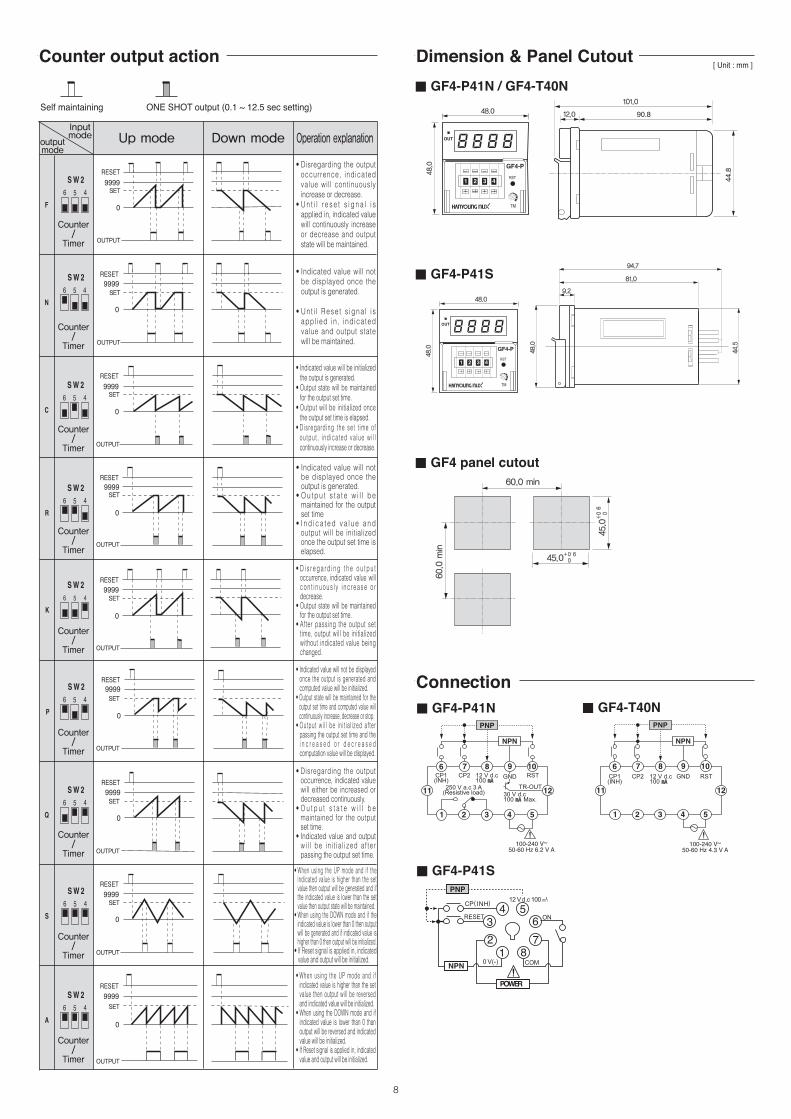
외형및패널가공치수
▒GF4-P41N/GF4-T40N외형치수
[ 단위 : mm ]
0 V(-)
RESET
COM
ON
CP(INH) 12 V d.c 100
NPN
POWER
PNP
0 V(-)
RESET
COM
ON
CP(INH) 12 V d.c 100
NPN
POWER
PNP
0 V(-)
RESET
COM
ON
CP(INH) 12 V d.c 100
NPN
POWER
PNP
60.0 이상
60.0
이상
45.0
45.0
44.5
48.0
81.0
9.2
94.7
101.0
48.0 12.0
48.0
▒GF4-P41N ▒GF4-T40N
▒GF4-P41S
60.0 이상
60.0
이상
45.0
45.0
44.5
48.0
81.0
9.2
94.7
101.0
48.0 12.0
48.0
60.0 이상
60.0
이상
45.0
45.0
44.5
48.0
81.0
9.2
94.7
101.0
48.0 12.0
48.0
접속도
▒GF4-P41S외형치수
▒GF4패널가공치수
5
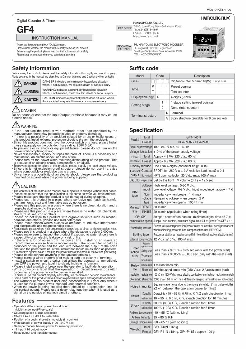
ModelTotal GF4-T40N
Preset GF4-P41N / GF4-P41SPower supply voltage 100 - 240 V a.c. 50 - 60 ㎐ Voltage fluctuation ±10 % of the power supply voltage
Powerconsumption
Total Approx 4.3 VA (220 V a.c 60 ㎐)Preset Approx 6.2 VA (220 V a.c 60 ㎐)
Display method Red FND 4 digits (character heigt : 8 ㎜)Controloutput
Contact SPDT (1c), 250 V a.c. 3 A resistive load, cosØ = 0.4Non-contact NPN open collector, 30 V d.c max, 100 ㎃ max
ONE SHOT output time Set by the front TM volume (0.1 s ~ 12.5 sec)
Input type
Voltage input
High level voltage : 5-30 V d.c.Low level voltage : 0-2 V d.c., Input impedance : approx 4.7 ㏀
Non-voltage
type
Impedance when breaks : 1 ㏀ maxRemaining voltage when breaks : 2 V, Impedance when opens : 100 ㏀ min
Min input time
RESET 20 ㎳ minINHIBIT 20 ㎳ min (Applicable when using timer)
CP1,CP2 computation speed
30 cps : contact/non-contact, minimum signal time 16.7 ㎳5 kcps : non-contact, minimum signal time 0.1 ㎳ (when ON/OFF = 1:1)
Power backup selectable Power failure compensation/power reset selectable, semi-permanent when selecting power failure compensation(use EEPROM)
Setting type Rrecognize at all times (possible to modify in the middle of applying electric current)External power supply 12 V d.c. ±10 %, 100 ㎃ max
Timeractionerror
Repeating operation error
Less than ± 0.01 % ± 0.05 sec (only with the power start)Less than ± 0.005 % ± 0.003 sec (only with the reset start)
Setting errorVoltage errorTemperature error
Relay life
Mechanical 1 million times minElectrical 100 thousand times min (250 V a.c. 2 A resistance load)
Insulation resistance 100 ㏁ min (500 V d.c. mega electric conduction terminal-non recharging metal)Dielectric strength 2000 V a.c. 60 ㎐ for 1min (different charging terminal from cach other)
Noise immunity Square wave noise due to the noise simulator (1 ㎲ pulse width)±2 ㎸ (between the operation power terminal)
VibrationDurability Durability / 10 ~ 55 ㎐, 0.75 ㎜, X, Y, Z each direction for 1 hour
Malfunction 10 ~ 55 ㎐, 0.5 ㎜, X, Y, Z each direction for 10 minutes
ShockDurability 300 ㎨ (30G) X, Y, Z each direction for 3 times
Malfunction 100 ㎨ (10G) X, Y, Z each direction for 3 timesAmbient temperature -10 ~ 55 ℃ (with no icing)
Ambient humidity 35 ~ 85 % R.HStorage temperature -20 ~ 65 ℃ (with no icing)
WeightTotal GF4-T40N : 168 g
Preset GF4-P41N : 184 g, GF4-P41S : approx 100 g
• Operates all functions by switches at front (Multi-range input/Free scale)• Counting speed 5 kcps selectable• ON-DELAY/OFF-DELAY selectable• Position of a decimal point is movable (in counter)• Wide ranges of power supply (100 - 240 V a.c)• Semi-permanent backup power for memory protection• 14 input / 16 output mode• Relay output and transistor output
Model Code DescriptionGF4 - ☐ ☐ ☐ ☐ Digital counter & timer 48(W) × 96(H) ㎜
TypeP Preset counterT Total counter
Displayable digit 4 4 digits (9999)
Setting stage1 1 stage setting (preset counter)0 None (total counter)
Terminal structureN TerminalS 8 pin structure (suitable for 8 pin socket)
Digital Counter & Timer
GF4 Thank you for purchasing HANYOUNG product. Please check whether the product is the exactly same as you ordered. Before using the product, please read this instruction manual carefully. Please keep this manual where you can view at any time
INSTRUCTION MANUAL
MD0104KE171109
1381-3, Juan-Dong, Nam-Gu Incheon, Korea. TEL:(82-32)876-4697FAX:(82-32)876-4696http://www.hynux.net
HANYOUNGNUX CO.,LTD
HEADOFFICE
Suffix code
Specification
Features
• The contents of the instruction manual are subjective to change without prior notice.• Please make sure that the specification is the same as what you have ordered.• Please make sure that the product is not damaged during shipping.• Please use this product in a place where corrosive gas (such as harmful
gas, ammonia, etc.) and flammable gas do not occur.• Please use this product in a place where there is no direct vibration and a
large physical impact to the product.• Please use this product in a place where there is no water, oil, chemicals,
steam, dust, salt, iron or others.• Please do not wipe this product with organic solvents such as alcohol,
benzene and others. (Please use mild detergent)• Please avoid places where excessive amounts of inductive interference
and electrostatic and magnetic noise occur.• Please avoid places where heat accumulation occurs due to direct sunlight or radiant heat.• Please use this product in a place where the elevation is below 2,000 m.• Please make sure to inspect the product if exposed to water since there is
a possibility of an electric leakage or a risk of fire.• If there is a lot of noise from the power line, installing an insulated
transformer or a noise filter is recommended. The noise filter should be grounded on the panel and the lead wire between the output of the noise filter and the power terminal of the instrument should be as short as possible.
• It is effective against noise if making the power lines of the product the twisted pair wiring.• Please do not connect anything to the unused terminals.• Please connect wires properly after making sure the polarity of terminal.• Install a switch or circuit breaker that allows the operator to immediately
turn OFF the power, and label it to clearly indicate its function.• Please install a switch or break near the operator to facilitate its operation. • Write down on a label that the operation of circuit breaker or switch
disconnects the power since the devise is installed.• In order to use this product properly and safely, we recommend periodic maintenance.• Some parts of this product have limited expected life span and aged deterioration.• The warranty of this product (including accessories) is 1 year only when it
is used for the purpose it was intended under normal condition. • When the power is being supplied there should be a preparation time for
the contact output. Please use a delay relay together when it is used as a signal on the outside of interlock circuit or others.
CAUTION
Do not touch or contact the input/output terminals because it may cause electric shock.
DANGER
• If the user use the product with methods other than specified by the manufacturer, there may be bodily injuries or property damages.
• If there is a possibility of an accident caused by errors or malfunctions of this product, install external protection circuit to prevent the accident.
• Since this product does not have the power switch or a fuse, please install those separately on the outside. (Fuse rating: 250V 0.5A)
• To prevent electric shock or equipment failure, please do not turn on the power until completing wiring.
• Never disassemble, modify, or repair the product. There is a possibility of a malfunction, an electric shock, or a risk of fire.
• Please turn off the power when mounting/dismounting of the product. This is a cause of an electric shock, a malfunction, or failure.
• To prevent damage or failure of this product, please supply the rated power voltage.• Since this is not explosion-proof structure, please do not use in a place
where combustible or explosive gas is around. • Since there is a possibility of an electric shock, please use the product as
mounted on a panel while the power is being supplied.
WARNING
Safety information
DANGER indicates an imminently hazardous situation which, if not avoided, will result in death or serious injuryWARNING indicates a potentially hazardous situation which, if not avoided, could result in death or serious injuryCAUTION indicates a potentially hazardous situation which, if not avoided, may result in minor or moderate injury
Before using the product, please read the safety information thoroughly and use it properly.Alerts declared in the manual are classified to Danger, Warning and Caution by their criticality
DANGER
WARNING
CAUTION
INDONESIAFACTORY Jl. Jangari RT.003/002 Hegarmanah
Sukaluyu Cianjur Jawa Barat Indonesia 43284TEL : +62-2140001930
PT. HANYOUNG ELECTRONIC INDONESIA
6
6
ON
OFF
5 4 3 2 1 6 5 4 3 2 1
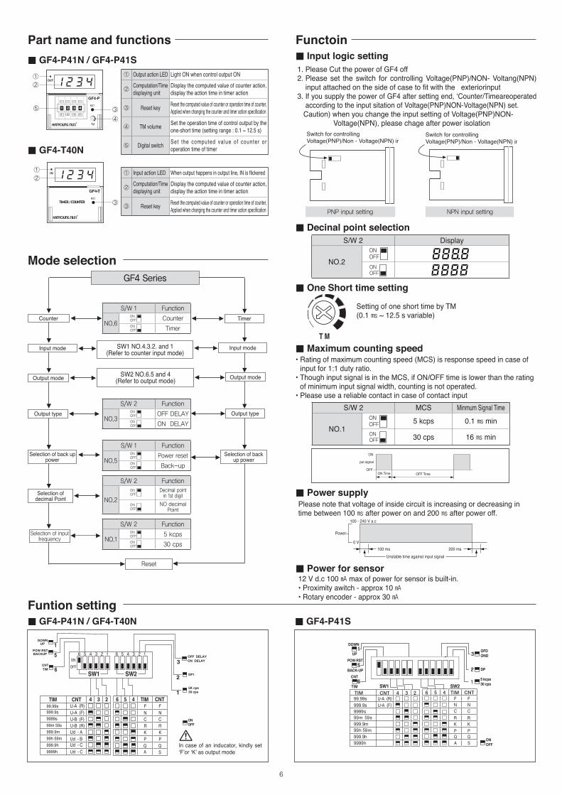
1. Please Cut the power of GF4 off2. Please set the switch for controlling Voltage(PNP)/NON- Voltang(NPN)
input attached on the side of case to fit with the exteriorinput3. If you supply the power of GF4 after setting end, ‘Counter/Timeareoperated
according to the input sitation of Voltage(PNP)NON-Voltage(NPN) set. Caution) when you change the input setting of Voltage(PNP)NON- Voltage(NPN), please chage after power isolation
T
①
②
③
T
①
②
⑤ ③
④
100100
PNP input setting NPN input setting
S/W 2 Display
NO.2
S/W 2 MCS Minmum Signal Time
NO.15 kcps 0.1 ㎳ min
30 cps 16 ㎳ min
Setting of one short time by TM(0.1 ㎳ ~ 12.5 s variable)
• Rating of maximum counting speed (MCS) is response speed in case of input for 1:1 duty ratio.
• Though input signal is in the MCS, if ON/OFF time is lower than the rating of minimum input signal width, counting is not operated.
• Please use a reliable contact in case of contact input
Please note that voltage of inside circuit is increasing or decreasing in time between 100 ㎳ after power on and 200 ㎳ after power off.
12 V d.c 100 ㎃ max of power for sensor is built-in.• Proximity awitch - approx 10 ㎃• Rotary encoder - approx 30 ㎃
In case of an inducator, kindly set ‘F’or ‘K’ as output mode
6
ON
OFF
5 4 3 2 1 6 5 4 3 2 1
TimerCounter
Output mode
Output type
Selection of decimal Point
Selection of input frequency
Input mode
Output mode
Output type
Selection of back up power
SW1 NO.4.3.2. and 1(Refer to counter input mode)
SW2 NO.6.5 and 4(Refer to output mode)
GF4Series
Selection of back up power
Reset
Input mode
S/W 2 Function
NO.15 kcps
30 cps
S/W 2 Function
NO.2
Decimal point in 1st digit
NO decimal Point
S/W 1 Function
NO.5Power reset
Back-up
S/W 2 Function
NO.3OFF DELAY
ON DELAY
S/W 1 Function
NO.6Counter
Timer
Part name and functions
Mode selection
Functoin
Funtion setting▒ GF4-P41N / GF4-T40N
▒ GF4-P41N / GF4-P41S ▒ Input logic setting
▒ Decinal point selection
▒ One Short time setting
▒ Maximum counting speed
▒ Power supply
▒ Power for sensor
▒ GF4-T40N
▒ GF4-P41S
① Output action LED Light ON when control output ON
② Computation/Time displaying unit
Display the computed value of counter action, display the action time in timer action
③ Reset key Reset the computed value of counter or operation time of counter,Applied when changing the counter and timer action specification
④ TM volume Set the operation time of control output by the one-short time (setting range : 0.1 ~ 12.5 s)
⑤ Digital switch Set the computed value of counter or operation time of timer
① Input action LED When output happens in output line, IN is flickered
② Computation/Time displaying unit
Display the computed value of counter action, display the action time in timer action
③ Reset key Reset the computed value of counter or operation time of counter,Applied when changing the counter and timer action specification
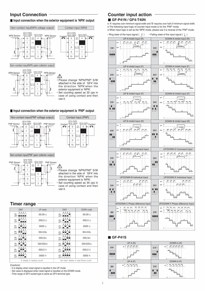
SW1 UP mode SW1 DOWN mode
99.99 s 99.99 s
999.9 s 999.9 s
9999 s 9999 s
99m59s 99m59s
999.9m 999.9m
99h595m 99h595m
999.9 h 999.9 h
9999 h 9999 h
‘0’ display in reset(up count) ‘Set value’ display in reset (Down count)
7
• Ring state of the input signal ( ) • Falling state of the input signal ( )
※ 'A' requires over minimum signal width and 'B' requires over half of minimum signal width.※ The following input logic of counter input mode is for the 'PNP' mode.※ When input logic is set as the 'NPN' mode, please use it is reverse of the 'PNP' mode.
Contact input (NPN)Non-contact input(NPN voltage output)
Non-contact input(NPN open collector output)
(Cautions) •0 is display when reset signal is inputted in the UP mode.•Set value is displayed when reset signal is inputted un the DOWN mode.•Time range of GF4 socket type is same as GF4 terminal type.
6 4
5
1
3
7
8
9
10
6 4
5
1
3
7
8
9
10
6 4
5
1
3
7
8
9
10
6 4
5
1
3
7
8
9
10
6 4
5
1
3
7
8
9
10
6 4
5
1
3
7
8
9
10
Contact input (PNP)
6 4
5
1
3
7
8
9
10
6 4
5
1
3
7
8
9
10
6 4
5
1
3
7
8
9
10
6 4
5
1
3
7
8
9
10
6 4
5
1
3
7
8
9
10
6 4
5
1
3
7
8
9
10
6 4
5
1
3
7
8
9
10
6 4
5
1
3
7
8
9
10
6 4
5
1
3
7
8
9
10
6 4
5
1
3
7
8
9
10
6 4
5
1
3
7
8
9
10
6 4
5
1
3
7
8
9
10
Non-contact input(PNP voltage output)
6 4
5
1
3
7
8
9
10
6 4
5
1
3
7
8
9
10
6 4
5
1
3
7
8
9
10
6 4
5
1
3
7
8
9
10
6 4
5
1
3
7
8
9
10
6 4
5
1
3
7
8
9
10
6 4
5
1
3
7
8
9
10
6 4
5
1
3
7
8
9
10
6 4
5
1
3
7
8
9
10
6 4
5
1
3
7
8
9
10
6 4
5
1
3
7
8
9
10
6 4
5
1
3
7
8
9
10
Non-contact input(PNP open collector output)
6 4
5
1
3
7
8
9
10
6 4
5
1
3
7
8
9
10
6 4
5
1
3
7
8
9
10
6 4
5
1
3
7
8
9
10
6 4
5
1
3
7
8
9
10
6 4
5
1
3
7
8
9
10
• Please change ‘NPN/PNP’ S/W attached in the side of ‘GF4’ into the direct ion ‘NPN’when the exterior equipment is ‘NPN’.
• Set counting speed as 30 cps in case of using contact and then use it.
• Please change ‘NPN/PNP’ S/W attached in the side of ‘GF4’ into the direction ‘NPN’ when the exterior equipment is ‘NPN’.
• Set counting speed as 30 cps in case of using contact and then use it.
A A
00
12
34
5
HL
HL
CP1
CP2
A A
0
HL
HL
CP1
CP2n
n-1n-2
n-3n-4
n-5
A A
00
12
34
5
H
LHL
CP1
CP2
A A
0
HL
HL
CP1
CP2n
n-1n-2
n-3n-4
n-5
A A
00
1 12 22
3 3
HLHL
CP1
CP2
0
A A
HLHL
CP1
CP2
n-1 n-1
n
n-2 n-2 n-2n-3 n-3
�n������ �n������
Inhibiti
�n������ �n������
�n������ �n������
Inhibiti Inhibiti
1
2
3
4
1
2
3
4
-1
-2
-3
-4
-1
-2
-3
-4
�� ����
A A
00
12
34
5
HL
HL
CP1
CP2
A A
0
HL
HL
CP1
CP2n
n-1n-2
n-3n-4
n-5
A A
00
12
34
5
H
LHL
CP1
CP2
A A
0
HL
HL
CP1
CP2n
n-1n-2
n-3n-4
n-5
A A
00
1 12 22
3 3
HLHL
CP1
CP2
0
A A
HLHL
CP1
CP2
n-1 n-1
n
n-2 n-2 n-2n-3 n-3
�n������ �n������
Inhibiti
�n������ �n������
�n������ �n������
Inhibiti Inhibiti
1
2
3
4
1
2
3
4
-1
-2
-3
-4
-1
-2
-3
-4
�� ����
Input Connection Counter input action
Timer range
▒ GF-P41N / GF4-T40N
▒ GF-P41S
▒ Input connection when the exterior equipment is ‘NPN’ output
▒ Input connection when the exterior equipment is ‘PNP’ output
8
Up modeInputmode
outputmode
Counter/
Timer
SET
OUTPUT
SET
OUTPUT
SET
OUTPUT
SET
OUTPUT
SET
OUTPUT
SET
OUTPUT
SET
OUTPUT
SET
OUTPUT
SET
OUTPUT
Counter/
Timer
Counter/
Timer
Counter/
Timer
Counter/
Timer
Counter/
Timer
Counter/
Timer
Counter/
Timer
Counter/
Timer
Down mode Operation explanation
ONE SHOT output (0.1 ~ 12.5 sec setting)Self maintaining
• Disregarding the output occurrence, indicated value wil l continuously increase or decrease.
• U n t i l r e s e t s i g n a l i s applied in, indicated value will continuously increase or decrease and output state will be maintained.
• Indicated value will not be displayed once the output is generated.
• Un t i l Rese t s igna l i s appl ied in , ind icated value and output state will be maintained.
• Indicated value will be initialized the output is generated.
• Output state will be maintained for the output set time.
• Output will be initialized once the output set time is elapsed.
• D is regard ing the set t ime o f ou tpu t , i nd ica ted va lue w i l l continuously increase or decrease.
• Indicated value will not be displayed once the output is generated.
• O u t p u t s t a t e w i l l b e maintained for the output set time
• I n d i c a t e d v a l u e a n d output will be initialized once the output set time is elapsed.
• D i s r e g a r d i n g t h e o u t p u t occurrence, indicated value will c o n t i n u o u s l y i n c r e a s e o r decrease.
• Output state will be maintained for the output set time.
• After passing the output set time, output will be initialized without indicated value being changed.
• Disregarding the output occurrence, indicated value will either be increased or decreased continuously.
• O u t p u t s t a t e w i l l b e maintained for the output set time.
• Indicated value and output w i l l be in i t ia l i zed a f te r passing the output set time.
• Indicated value will not be displayed once the output is generated and computed value will be initialized.
• Output state will be maintained for the output set time and computed value will continuously increase, decrease or stop.
• Output wi l l be in i t ia l ized af ter passing the output set time and the i n c r e a s e d o r d e c r e a s e d computation value will be displayed.
• When using the UP mode and if indicated value is higher than the set value then output will be reversed and indicated value will be initialized.
• When using the DOWN mode and if indicated value is lower than 0 than output will be reversed and indicated value will be initialized.
• If Reset signal is applied in, indicated value and output will be initialized.
• When using the UP mode and if the indicated value is higher than the set value then output will be generated and if the indicated value is lower than the set value then output state will be maintained.
• When using the DOWN mode and if the indicated value is lower than 0 then output will be generated and if indicated value is higher than 0 then output will be initialized.
• If Reset signal is applied in, indicated value and output will be initialized.
60.0 이상
60.0
이상
45.0
45.0
44.5
48.0
81.0
9.2
94.7
101.0
48.0 12.0
48.0
60.0 이상
60.0
이상
45.0
45.0
44.5
48.0
81.0
9.2
94.7
101.0
48.0 12.0
48.0
▒ GF4-P41N / GF4-T40N[ Unit : mm ]
RESET
CP(INH) 12 V d.c 100
NPN
POWER
PNP
0 V(-) COM
ONRESET
CP(INH) 12 V d.c 100
NPN
POWER
PNP
0 V(-) COM
ON
RESET
CP(INH) 12 V d.c 100
NPN
POWER
PNP
0 V(-) COM
ON
60.0 min
60.0
min
45.0
45.0
44.5
48.0
81.0
9.2
94.7
101.0
48.0 12.0
48.0
▒ GF4-P41N ▒ GF4-T40N
▒ GF4-P41S
60.0 이상
60.0
이상
45.0
45.0
44.5
48.0
81.0
9.2
94.7
101.0
48.0 12.0
48.0
60.0 이상
60.0
이상
45.0
45.0
44.5
48.0
81.0
9.2
94.7
101.0
48.0 12.0
48.0
▒ GF4-P41S
▒ GF4 panel cutout
Counter output action Dimension & Panel Cutout
Connection
![사용설명서 완벽사용가이드 - RICOH IMAGING...간단가이드 [사용설명서(간단가이드)])] Caplio CD-ROM 소프트웨어와[사용설명서(완벽사용가이드)]가](https://img.pdfslide.net/doc/110x75/604848491792a43c1823b282/eoe-eeeoe-ricoh-eeeeoe-eoeeeeeoe.jpg)


![[스포츠 학습 앱] 자세의정석 : 야구 사용설명서](https://img.pdfslide.net/doc/110x75/55a8b8a41a28ab67288b45fb/-55a8b8a41a28ab67288b45fb.jpg)