Embed Size (px)
Citation preview
Measurements & Electrical Analog Devices (Part 2)
Introduction
Analog Signal Conditioning: Amplifiers Analog Signal Conditioning: Filters Grounds, Shielding & Connecting Wires
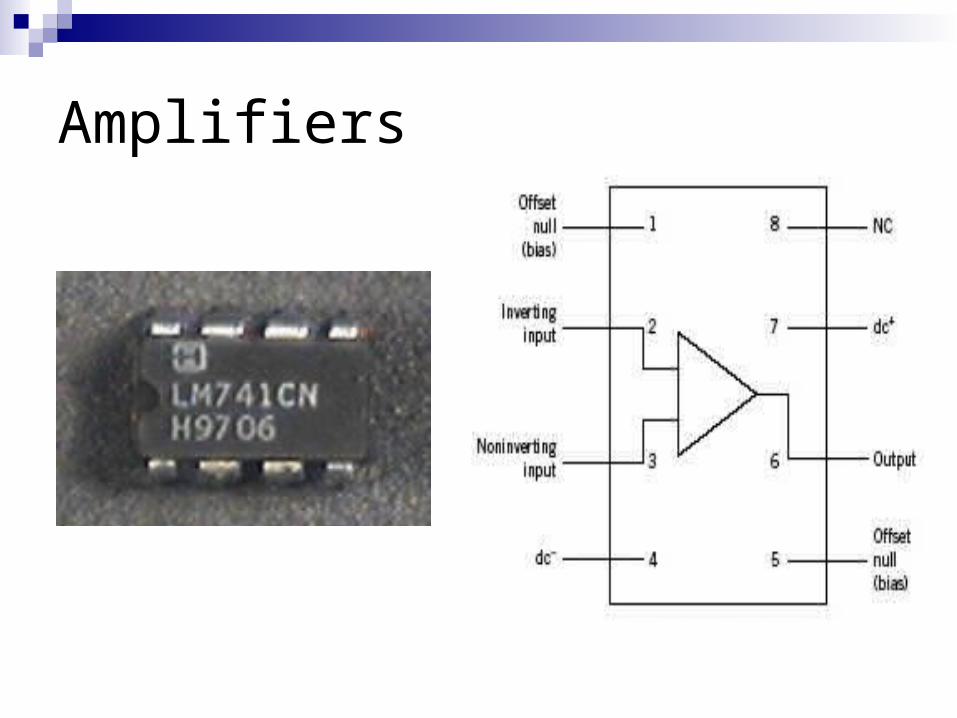
Amplifiers
Amplifier - device that scales the magnitude of an analog input signal according to
E0(t) = h{Ei(t)} Simplest amplifier = linear scaling amplifier:
h{Ei(t)} = GEi(t) Have finite frequency response & limited input voltage
range Most widely used – solid-state operational amplifier
Amplifiers
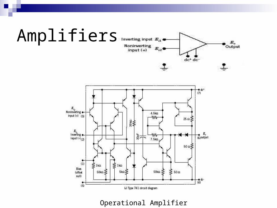
Amplifiers
Operational Amplifier
Amplifiers
High internal gain, A:
E0 = A [Ei2(t) – Ei1(t)] A – flat at low frequencies, falls off rapidly
at high frequencies but can overcome using external input and feedback resistors (control G)
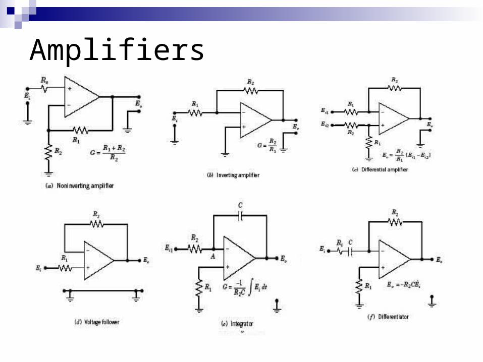
Amplifiers
Filters
Filter = used to remove undesirable frequency information from a dynamic signal
Classified as low pass, high pass, bandpass and notch
An introduction to signal…
Measurement system – takes input quantity / signal & transforms into measurable output quantity / signal
Shape / form of signal = waveform Waveform – information on magnitude,
amplitude, frequency
Definition of signal
Signal = physical information about a measured variable being transmitted from one place to another (between a process and the measurement system, between the stages of a measurement system, or the output from a measurement system)
Classification of signals
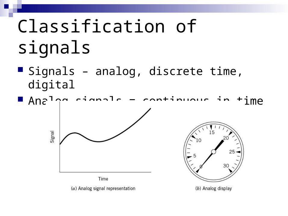
Signals – analog, discrete time, digital Analog signals = continuous in time
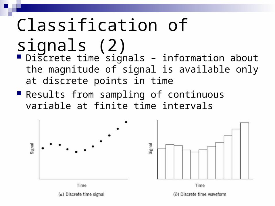
Classification of signals (2) Discrete time signals – information about the
magnitude of signal is available only at discrete points in time
Results from sampling of continuous variable at finite time intervals
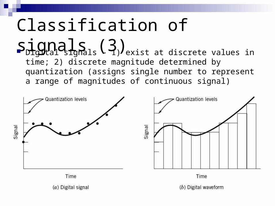
Classification of signals (3) Digital signals – 1) exist at discrete values in time; 2)
discrete magnitude determined by quantization (assigns single number to represent a range of magnitudes of continuous signal)
Signal Waveforms
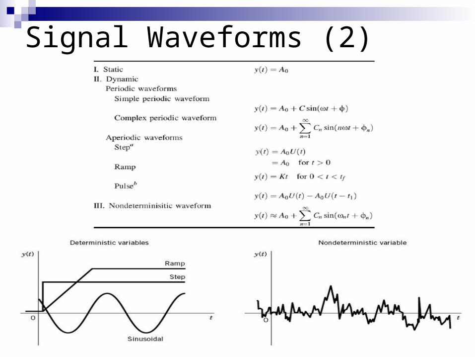
Static signal = does not vary with time Dynamic signal = time-dependent signal Deterministic signal = varies in time in
predictable manneri) Periodic = variation of magnitude repeats at
regular intervals in timeii) Aperiodic = do not repeat at regular intervals Nondeterministic = has no discernible pattern of
repitition
Signal Waveforms (2)
Filters
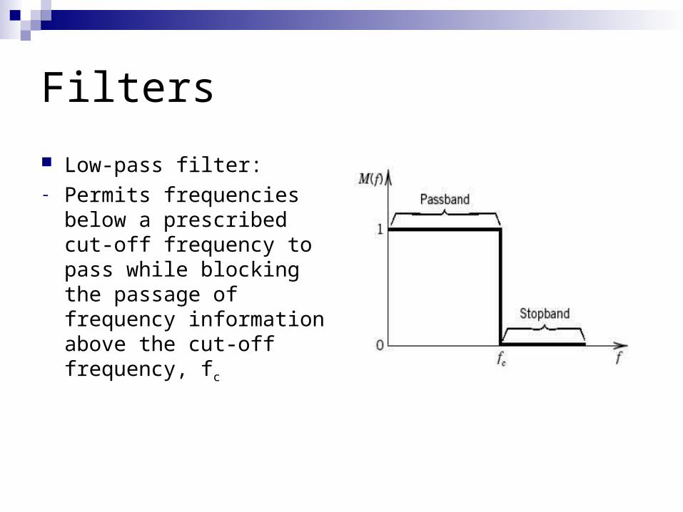
Low-pass filter:- Permits frequencies
below a prescribed cut-off frequency to pass while blocking the passage of frequency information above the cut-off frequency, fc
Filters
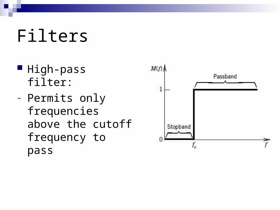
High-pass filter:- Permits only
frequencies above the cutoff frequency to pass
Filters
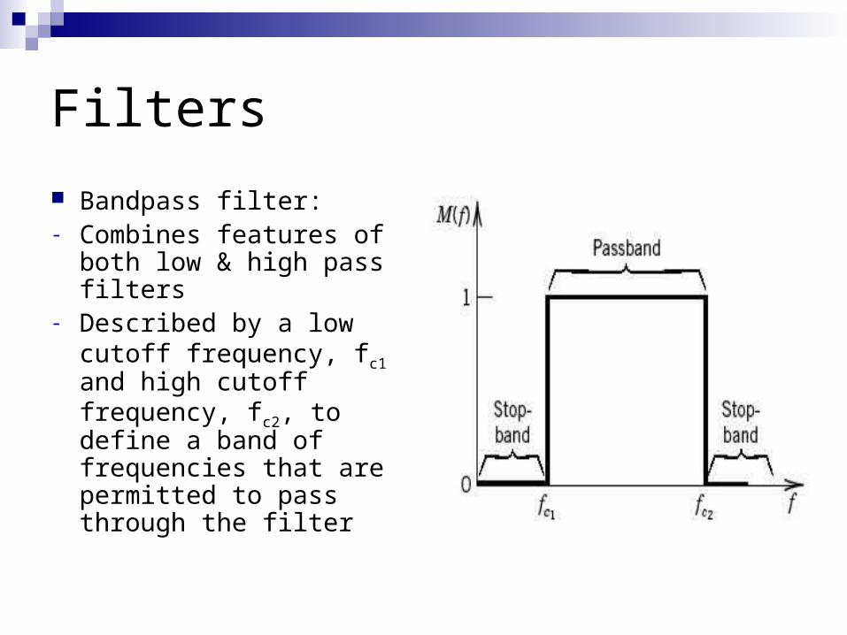
Bandpass filter:- Combines features of
both low & high pass filters
- Described by a low cutoff frequency, fc1 and high cutoff frequency, fc2, to define a band of frequencies that are permitted to pass through the filter
Filters
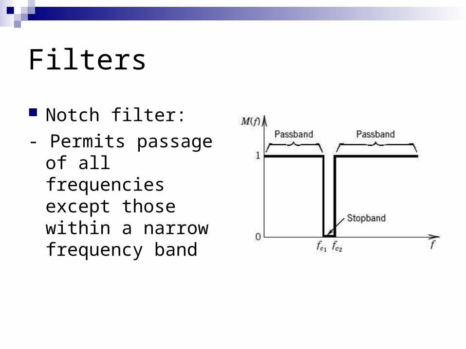
Notch filter:
- Permits passage of all frequencies except those within a narrow frequency band
Filters
Passive filters – combinations of resistors, capacitors and inductors
Active filters – incorporate operational amplifiers
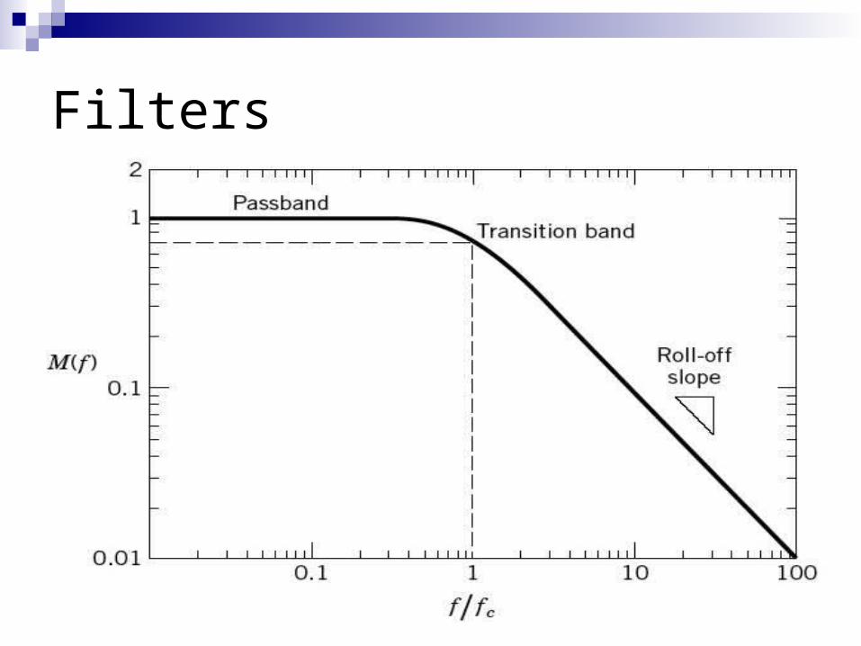
Important terms – roll-off (rate of transition where the magnitude ratio decreases relative to the frequency – dB/decade); phase shift (between input & output signal)
Filters
Butterworth Filter Design
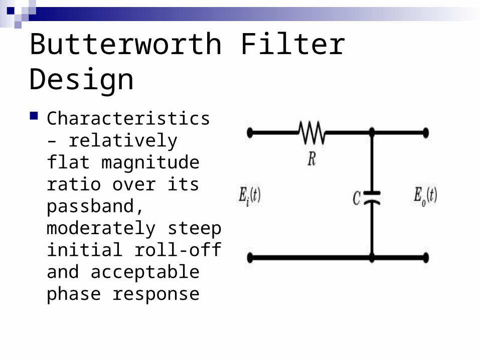
Characteristics – relatively flat magnitude ratio over its passband, moderately steep initial roll-off and acceptable phase response
Butterworth Filter Design
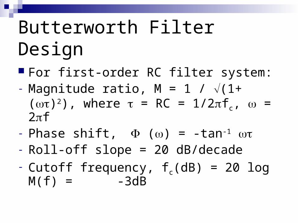
For first-order RC filter system:- Magnitude ratio, M = 1 / (1+ ()2), where
= RC = 1/2fc, = 2f- Phase shift, () = -tan-1 - Roll-off slope = 20 dB/decade- Cutoff frequency, fc(dB) = 20 log M(f) =
-3dB
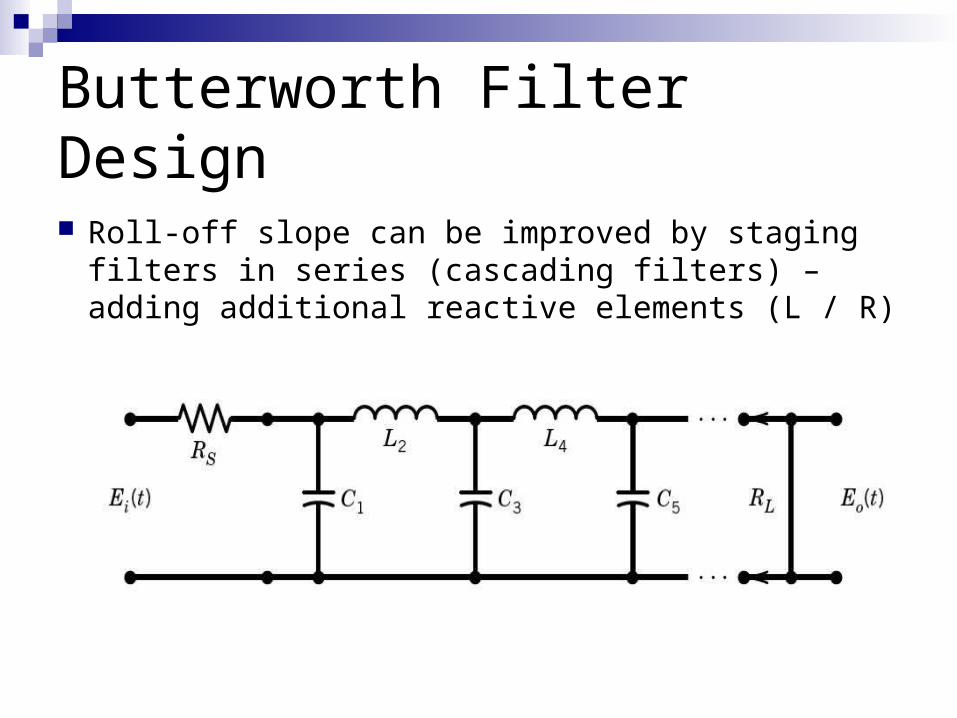
Butterworth Filter Design
Roll-off slope can be improved by staging filters in series (cascading filters) – adding additional reactive elements (L / R)
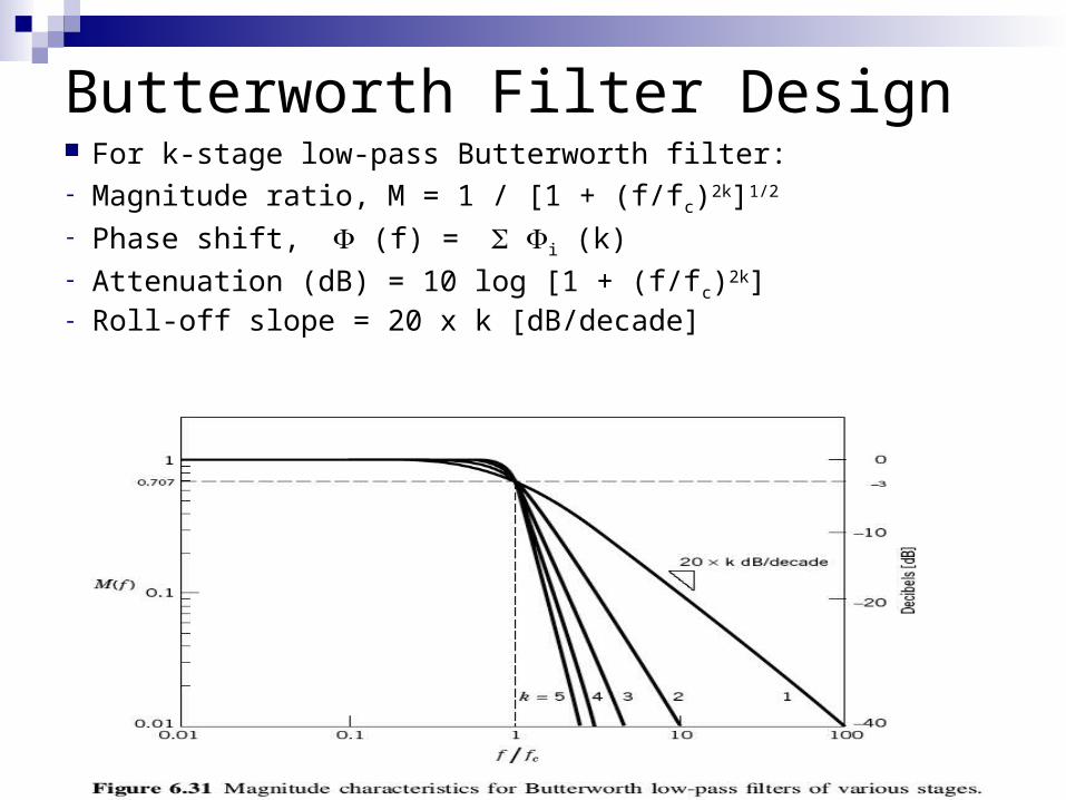
Butterworth Filter Design For k-stage low-pass Butterworth filter:- Magnitude ratio, M = 1 / [1 + (f/fc)2k]1/2
- Phase shift, (f) = i (k)- Attenuation (dB) = 10 log [1 + (f/fc)2k]- Roll-off slope = 20 x k [dB/decade]
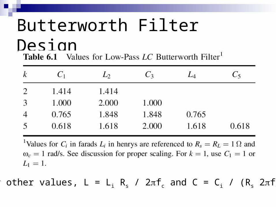
Butterworth Filter Design
For other values, L = Li Rs / 2fc and C = Ci / (Rs 2fc)
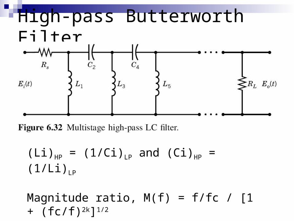
High-pass Butterworth Filter
(Li)HP = (1/Ci)LP and (Ci)HP = (1/Li)LP
Magnitude ratio, M(f) = f/fc / [1 + (fc/f)2k]1/2
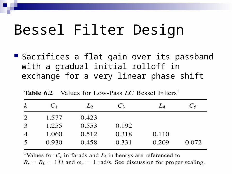
Bessel Filter Design
Sacrifices a flat gain over its passband with a gradual initial rolloff in exchange for a very linear phase shift
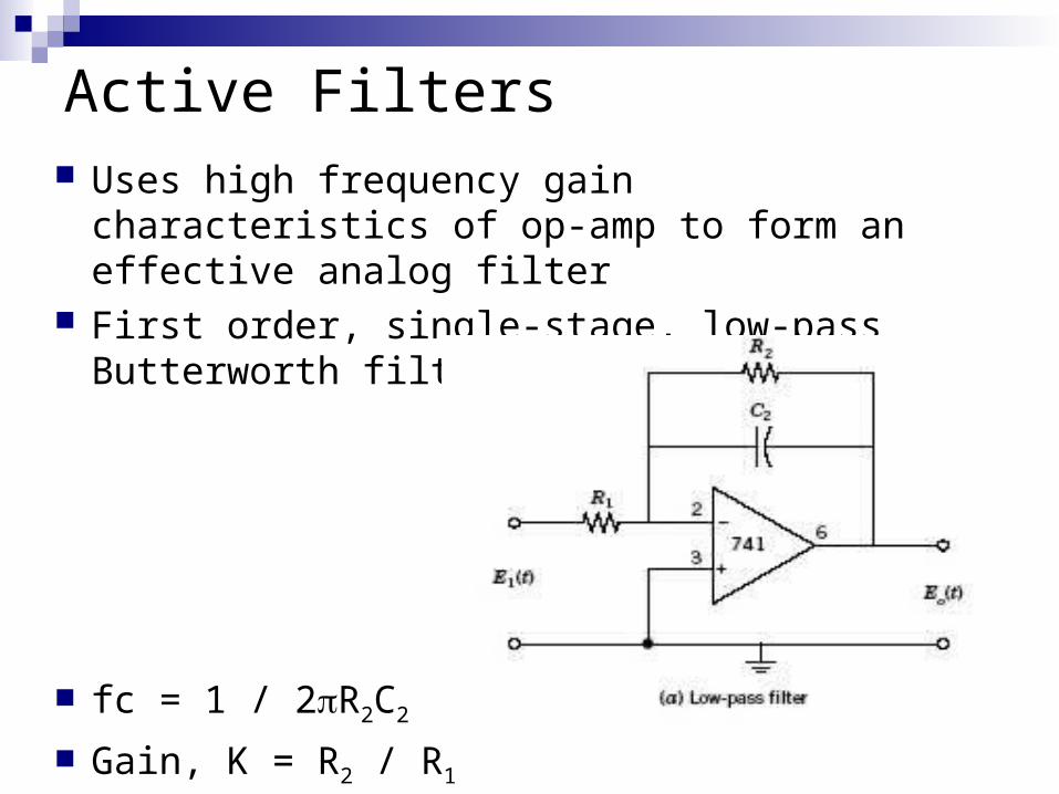
Active Filters Uses high frequency gain characteristics of op-
amp to form an effective analog filter First order, single-stage, low-pass Butterworth
filter:
fc = 1 / 2R2C2
Gain, K = R2 / R1
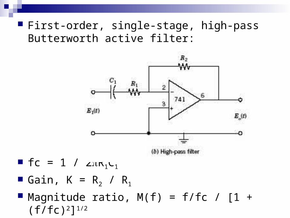
First-order, single-stage, high-pass Butterworth active filter:
fc = 1 / 2R1C1
Gain, K = R2 / R1
Magnitude ratio, M(f) = f/fc / [1 + (f/fc)2]1/2
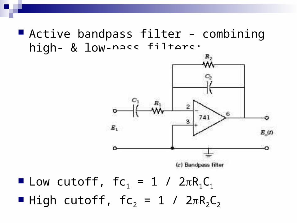
Active bandpass filter – combining high- & low-pass filters:
Low cutoff, fc1 = 1 / 2R1C1
High cutoff, fc2 = 1 / 2R2C2
Grounds, Shielding & Connecting Wires Rules to keep noise levels low:1) Keep the connecting wires as short as
possible2) Keep signal wires away from noise
sources3) Use a wire shield and proper ground4) Twist wire pairs along their lengths
Ground & Ground Loops
Ground = a return path to earth Ground loops = caused by connecting a
signal circuit to two / more grounds that are at different potentials
Ensure a system has only one ground point
Shields & Connecting Wires
Shield = a piece of metal foil or wire braid wrapped around the signal wires and connected to ground
Different type of wires – single cable, flat cable, twisted pair of wires, coaxial cable, optical cable