Embed Size (px)
Citation preview
Ple
ase
note
that
this
is a
n au
thor
-pro
duce
d P
DF
of a
n ar
ticle
acc
ept
ed fo
r pu
blic
atio
n fo
llow
ing
peer
rev
iew
. The
def
initi
ve p
ub
lish
er-a
uthe
ntic
ated
ve
rsio
n is
ava
ilab
le o
n th
e pu
blis
her
Web
site
1
Ocean Engineering December 2011, Vol. 38 (17-18), Pages 2208-2214 http://dx.doi.org/10.1016/j.oceaneng.2011.10.010 © 2011 Elsevier Ltd. All rights reserved.
Archimerhttp://archimer.ifremer.fr
Mechanical behaviour of HMPE and aramid fibre ropes for deep sea handling operations
Peter Daviesa, * Yvan Reaudb, Loic Dussuda, Patrice Woerthera
a IFREMER Centre de Brest, Plouzané, France b DT INSU C2FN Océan—IPEV Océanographie, France *: Corresponding author : Peter Davies, Tel.: +33 298 22 4777 ; fax: +33 298 22 4535 email address : [email protected]
Abstract : This paper describes the mechanical behaviour of ropes used for deep sea oceanographic operations. First the requirements of deep sea handling ropes are presented. Two high performance fibres are commonly used, aramid co-polymer and high modulus polyethylene (HMPE), and these are then compared. Results from tests on single fibres and 50 ton break load braided ropes are presented, which show that the initial stiffness of a new HMPE rope increases with load level in a bedding-in process resulting from both molecular alignment and construction reorientation. The aramid rope is less sensitive to this effect and shows a high stiffness from first loading. Measurements made at sea on oceanographic ropes of both materials using an elastic recoil method are presented, and apparent modulus values are consistent with laboratory measurements. Once both ropes have been fully bedded-in the HMPE is significantly stiffer, particularly under dynamic loads. Creep tests indicate that aramids creep less quickly than HMPE under constant loads over a 6 h period at 20 °C. Bending over sheave tests indicate longer lifetimes for the aramid but further tests on wet aramid are required to complete this conclusion.
Highlights
► Original data on the mechanical behaviour of two types of deep sea handling rope. ► New results from measurements at sea. ► A discussion of the relative merits of aramid and HMPE fibre ropes for this application.
Keywords : Fibre rope ; Deep sea coring ; Stiffness ; Aramid ; HMPE
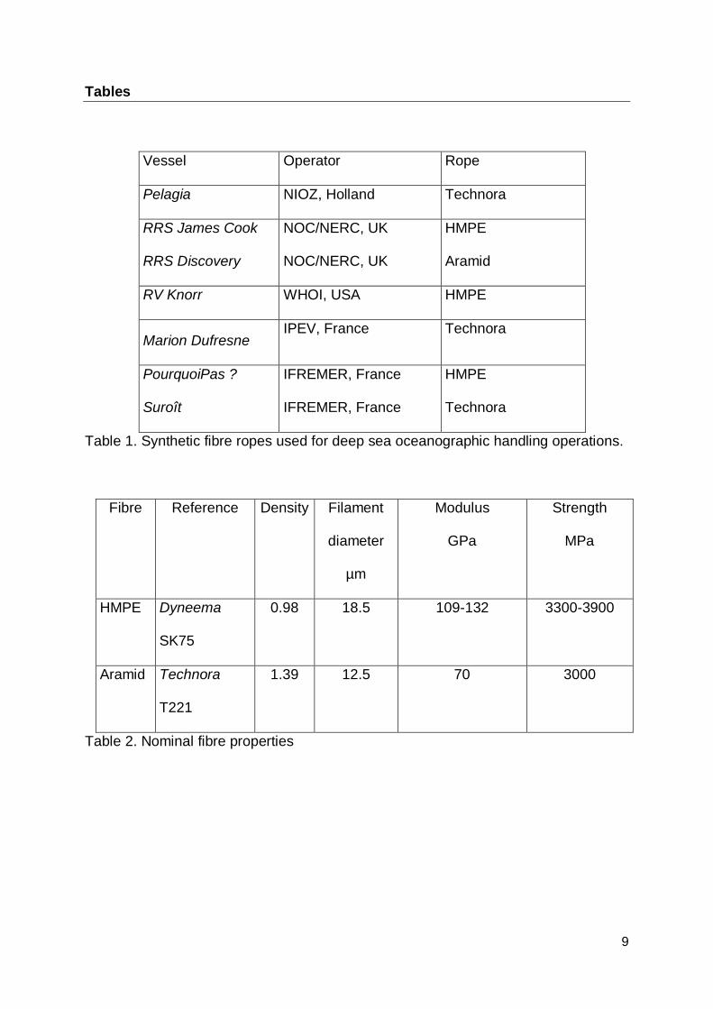
1. Introduction Marine sediments can provide a high-resolution record of environmental change over a geological timescale. Young et al. (2000) and Brandes (2011) have given recent examples of the geotechnical information that seabed core samples can provide. The key to recovering accurate sediment records is to maintain the dimensional accuracy of the sediment layers in the recovered core sample. One oceanographic operation which provides valuable deep sea sediment information is coring, either gravity coring in which tubes are pushed into the ocean floor under their own weight then extracted and lifted to the surface, or gravity piston coring (using large Calypso or Kuhlenberg corers) in which a trigger system drops a weighted tube up to 60 meters long which penetrates into the sea floor (Skinner and McCave, 2003). With nearly 60% of the seafloor at depths of 4000 meters or more this is not a trivial operation. The Calypso giant corer was introduced about 15 years ago and would have required 5 tons of steel wire cable for coring even at 3000 meters depth. The use of new synthetic fibre rope materials, lighter but with an elastic recoil 4 times more important, is thus essential, but requires new operational procedures. The sampling equipment weighs several tons, so ropes up to 6000 metres long with break loads from 20 up to over 50 tons are needed. Synthetic ropes have been proposed for many years, Houbolt (1971) among others used polypropylene ropes to obtain short cores in the 1960’s, but this is quite a low stiffness material. The quality of long core samples depends on the stiffness of the rope, higher stiffness is preferable to reduce elastic recoil during penetration (Széréméta et al, 2004), and damping capacity is needed to limit the movements of the piston which damage the sample. There are other requirements for a handling rope however, notably the ability to bend over sheaves repeatedly without damage, a balanced torque-free construction to limit twisting, the ease of making terminations at sea, ease of reeling on storage drums, and the possibility to repair after damage. There are few vessels in the world capable of performing operations at these depths, as it requires special winches, large storage capacity drums and considerable expertise. Table 1 describes some of them, and indicates the rope materials in use today. It is clear from this Table that two types of material are in use for this application, aramid copolymer ropes made of Technora fibres and HMPE based on Dyneema and Spectra. Both materials have advantages and disadvantages, but few independent data are available on such ropes. This aramid copolymer is used rather than more traditional aramid fibres (Kevlar, Twaron) as it is believed to show better fatigue behaviour. Mower (2000) has shown some results. Defining the stiffness of fibre ropes is more complex than for steel, as the stiffness values depend to a greater or lesser extent on several parameters. These include the mean load level, the load amplitude, the loading rate, and the previous loading history. Various previous studies, notably those of Del Vecchio (1992), Fernandes et al (1999) and François et al (2010) have described the influence of these parameters on the behaviour of polyester and other synthetic fibres in mooring lines. A test campaign to measure stiffness can therefore be quite time consuming, and the ISO Committee has spent considerable time in defining test procedures for mooring line applications (ISO 2007). This paper will describe results from stiffness tests on the two rope materials in order to provide data to assist in the choice of ropes for this application. Additional tests have been performed on fibres, in order to clarify the origins of the results. Some stiffness measurements made at sea with the same ropes during recent campaigns will also be described. Finally, other important properties such as the bend-over-sheave (BOS) behaviour of ropes based on the two fibres will be discussed.
2
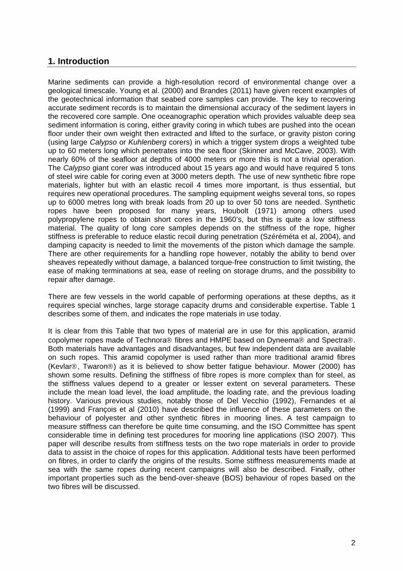
2. Materials The two main types of fibres employed today for oceanographic ropes are aramid copolymers and HMPE. These are generic fibre types, covering a large range of grades, Table 2 compares the nominal properties of two specific fibres used in handling lines, based on suppliers’ data (DSM, Teijin). These will be referred to as HMPE and aramid hereafter, but the reader should note that both these generic fibre types can be found in grades with both higher and lower properties. Based on these data it is clear that these HMPE fibres are lighter (they float) and stronger than this particular aramid grade, but this is only part of the picture. In order to use these materials they must be transformed into ropes, requiring a large number of operations including twisting and braiding. This inevitably leads to a reduction in properties, so the fibre properties cannot be used directly to design ropes. Rope mechanics analyses, based on fibre and yarn properties together with construction geometry have been developed and can be useful in rope design but still require experimental validation for a particular construction (e.g. Leech et al. 2003). Figure 1 shows two rope constructions currently in use which will be studied in detail here. Both have similar nominal outer diameters (around 30mm), but the constructions are quite different. The HMPE is a 12-strand braid without an external cover, the aramid is a 16x2 strand braid with an extruded outer jacket in polyester elastomer and a light polyester braid between the jacket and the aramid fibres. The comparison between them is made on a similar diameter basis here, as it is this which determines sheave size (D/d ratio), and the storage space required on board the vessel. It should be noted however that the notion of diameter is not easily applicable to the HMPE braid, whose section is not perfectly round and whose diameter changes during loading. Also, rope weight and strength are not identical, and the comparison could also be made based on various other parameters, including purchase or lifetime cost. Fibre ropes are hierarchical structures with several scale levels. Those tested here are composed of twisted yarn assemblies, known as rope yarns, which are themselves twisted together in the opposite direction into strands which are then braided together. A detailed discussion of rope-making operations is given by McKenna et al. (2004). There are 108 rope yarns in the HMPE rope studied here and 128 in the aramid rope.
3. Test procedures The basic rope element is the individual fibre or filament. It is useful to examine fibre behaviour, as it allows the material response to be separated from effects added by the rope construction, but fibre tests are difficult to perform and can show considerable scatter. A small number of single fibre tests were performed in a DMA (TA 2980 Dynamic Mechanical Analyser) using the ASTM method D3822 (ASTM 2007), in which fibres are bonded to a cardboard frame. This allows the fibre to be aligned on the test machine, the frame sides are cut before testing. Fibre diameter was measured on each sample after testing, in a scanning electron microscope. Then tensile tests were performed on full size rope samples 8 meters long with spliced ends terminations, on a 100 ton test frame, Figure 2. Spliced loops were placed over 100mm diameter loading pins. The main test programme, which required 2 weeks of testing, was performed on one sample of each rope. The test machine controller was programmed so that exactly the same loads were applied to all samples. The elongation was measured in the central section of the ropes over a length of 3 metres using a wire displacement transducer clamped to the rope. Overall length (piston displacement) was also recorded, using an LVDT
3
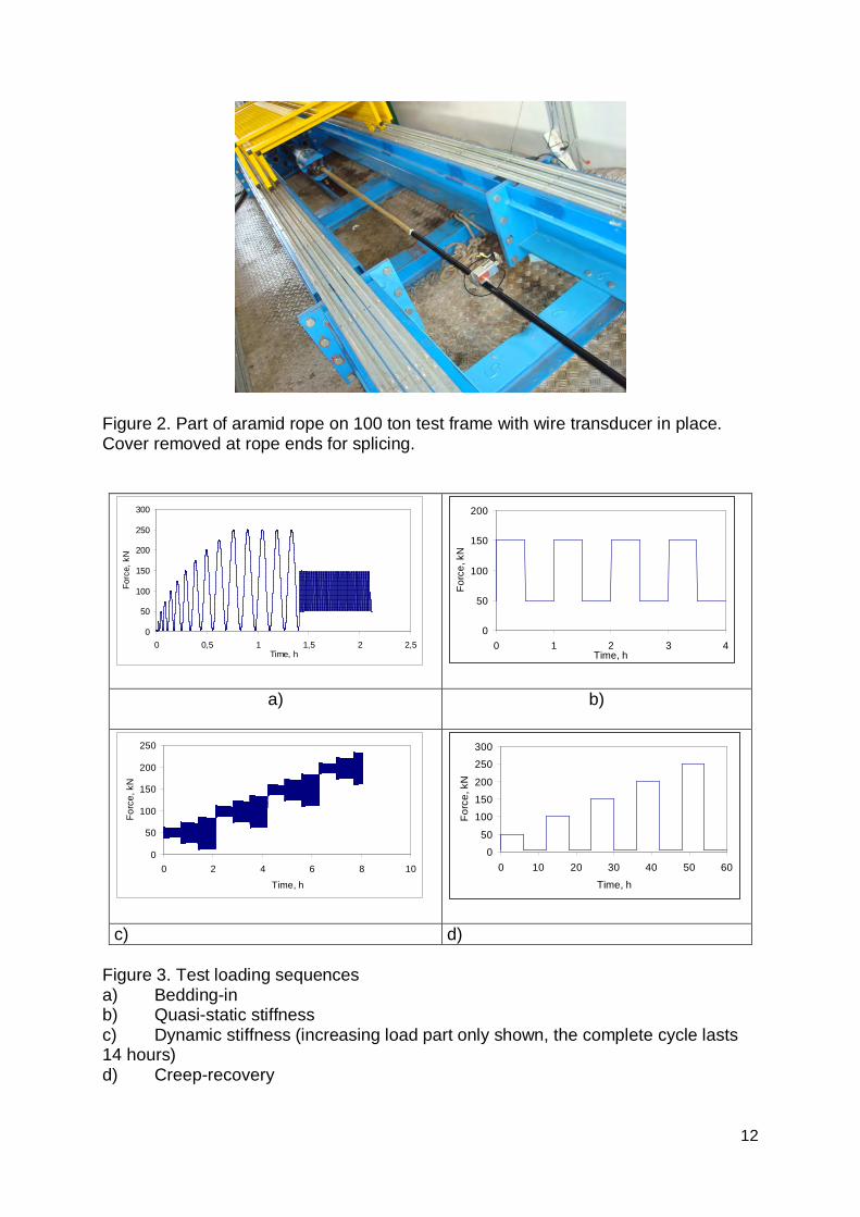
in the piston, but this was not used for stiffness calculations as it includes splice and end loop movements. The tests performed were based on the procedures in the ISO document developed for offshore mooring lines, with some modifications which will be described. Figure 3 shows the overall test sequence for each rope, which lasted 80 hours. After a bedding-in sequence 4 quasi-static cycles were applied between 10 and 30% of the minimum break load or MBL. MBL was taken to be 500 kN for both ropes. Then a dynamic stiffness sequence was performed, with measurements at increasing mean loads of 10, 20, 30 and 40% of MBL followed by decreasing 30, 20 and 10% values. Three amplitudes were applied at each mean load level, with 100 cycles for each condition at a period of 25 seconds. Finally a creep-recovery sequence was followed with increasing constant load periods of 6 hours up to 50% MBL.
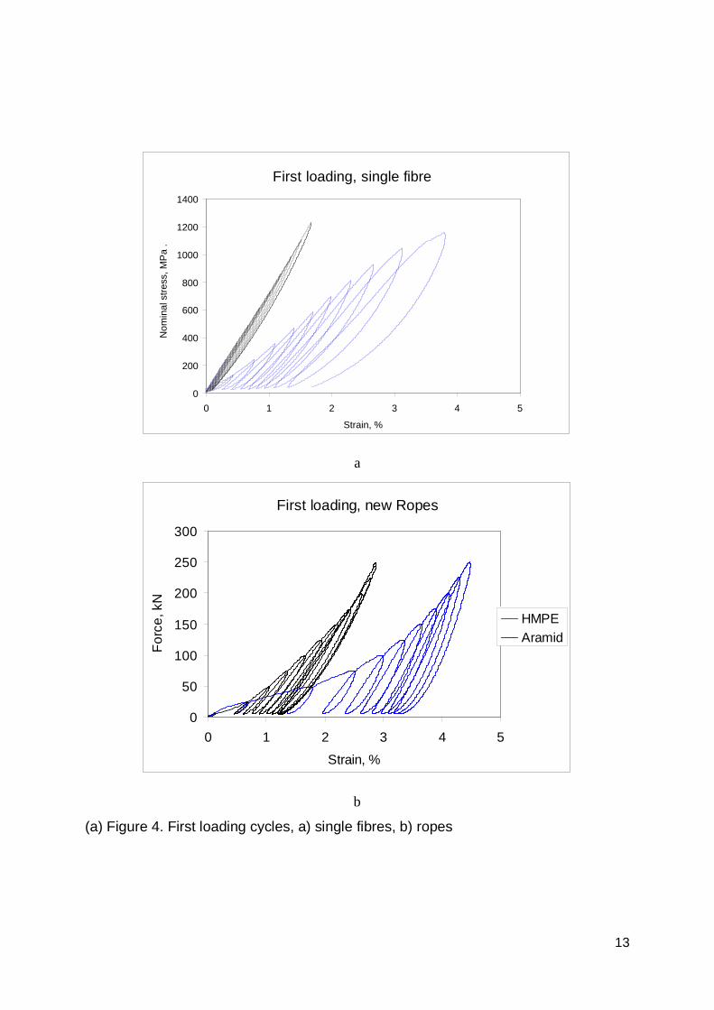
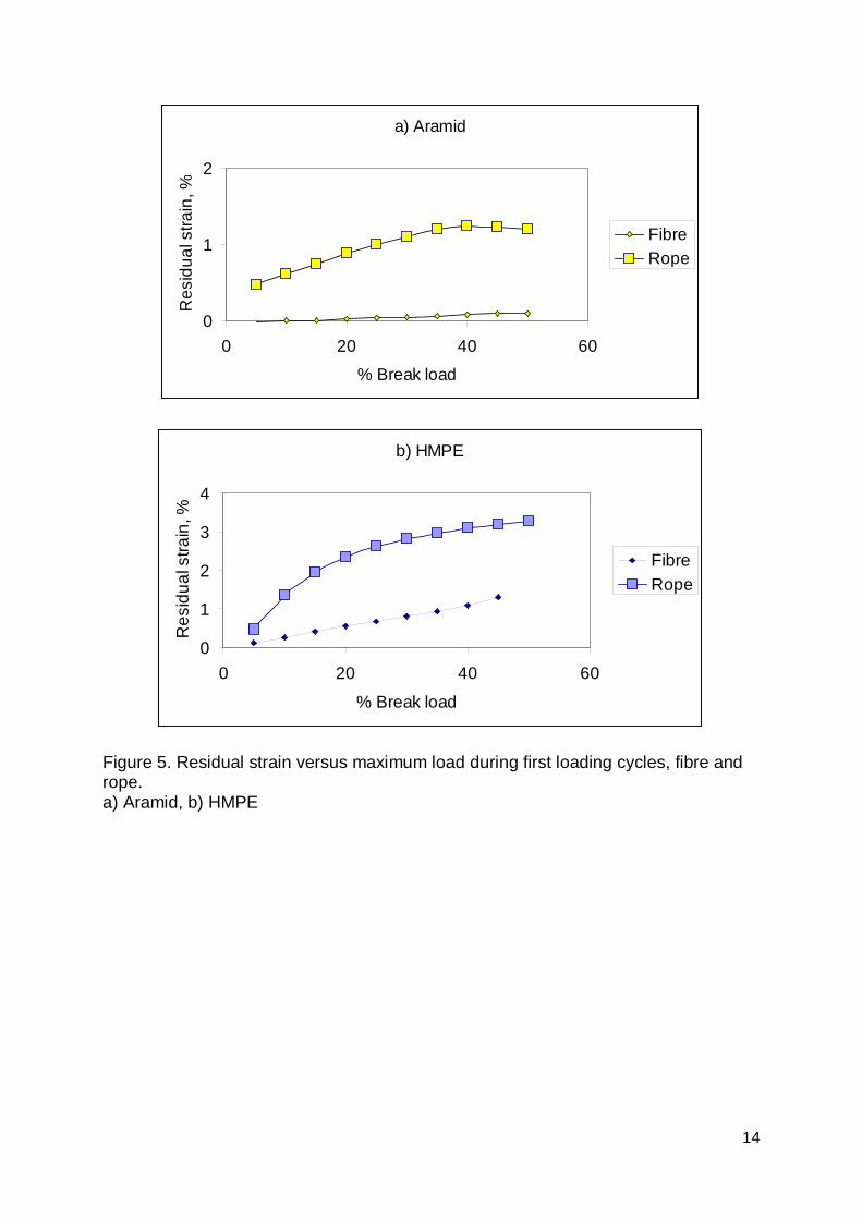
4. Results from laboratory tests 4.1 First loading Figure 4a shows examples of results from first tests on fibres taken from the ropes, with increasing load levels up to 50% of measured fibre strengths (2400 MPa for both fibres). Mean filament diameter was measured to be 18.5 m for the HMPE and 12.5 m for the aramid. The results in Figure 4a indicate that a new aramid fibre is very stiff from the first loading at low loads, while the HMPE fibre requires higher loads before it reaches high stiffness values and shows large hysteresis on unloading. Figure 4b shows the response of new ropes to similar loading, with increasing load levels up to 50% MBL. This is not exactly the ISO rope procedure, which recommends a single load-unload cycles to 50% with a 30 minute hold time, but the advantage of the progressive increase used here is that the load level influence on residual strain can be evaluated. Both ropes show a residual strain on unloading. The first time the aramid is loaded to 20% of its break load a residual strain around 1% is measured, while at the same load level the HMPE residual strain is closer to 2.5%. This increase in stiffness as the load is increased for the first time and permanent residual strain is the well-known “bedding-in” phenomenon in synthetic fibre ropes (Northolt et al. 1985). For aramid fibres Northolt defined an expression with an orientation parameter, including the permanent and retarded reorientations of crystallites which align with the stress direction. This re-orientation occurs both at a molecular scale within the fibres and also at a rope construction level as rope elements re-align in the load direction. There are few clear indications in the literature on the relative contributions of these two mechanisms but by performing similar load-unload tests on both single fibres and ropes it is possible to clarify this. This residual strain is important as it affects the apparent stiffness. Figure 5 shows values for both materials, for fibres and ropes. The aramid rope residual strain is mainly due to the construction, the contribution from the fibres is very small. For the HMPE rope however, there is a significant contribution from the fibres, but once again it is the construction reorientation which accounts for most of the residual strain. It should be emphasized that the comparison between fibre and rope is based on percentage values of measured break loads for both. When a rope is loaded to 20% of its break load the individual fibres in the rope will not be subjected to 20% of their failure load, as the strength conversion efficiency from fibre to rope is always below 100%. Due to this, the material contribution to the bedding-in strain will probably be even lower than that
4
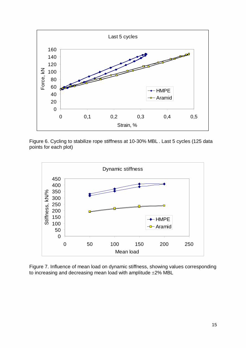
obtained in Figure 5 simply by comparing the residual strains at equivalent % break loads. Various rope models have been developed to estimate the load transfer at different levels in rope constructions (Leech et al 1993), but these are not simple analyses due to the large number of rope elements and the need to model the many interactions between them (Leech 2002). After first loading the ropes were subjected to 100 cycles in the 10-30% MBL range to stabilize them, as recommended in the ISO guidelines (ISO 2007). These cycles, which are in the working range of these ropes during coring operations, clearly show the differences in behaviour. Figure 6 shows the 95th to 100th cycles for both materials. These results indicate two features. First, the stiffness at the end of the bedding-in sequence (i.e. after the rope has been loaded to 50% of MBL) is higher for the HMPE rope. Second, the damping behaviour, as indicated by the hysteresis loops recorded during cycling, is also significantly higher for the HMPE rope. 4.2 Quasi-static and Dynamic stiffness
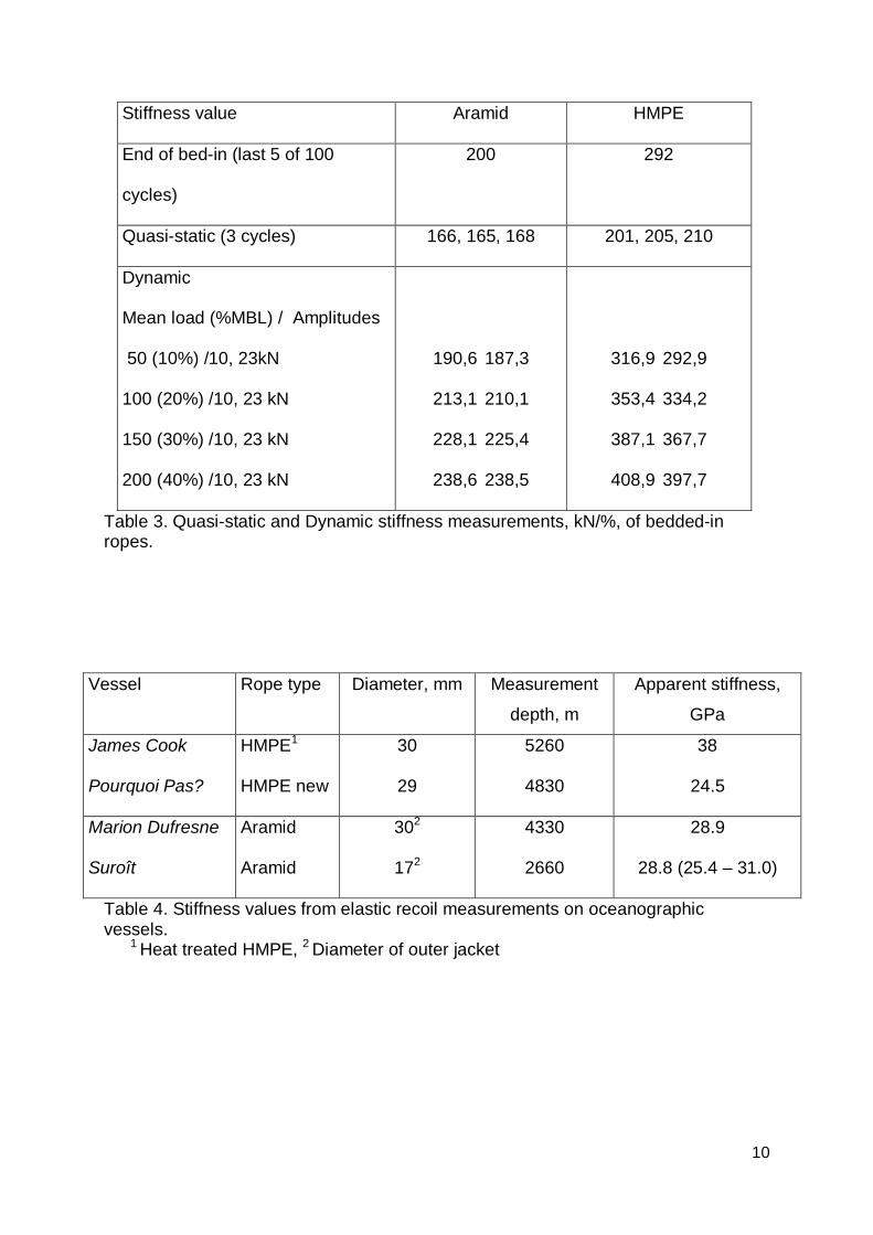
After stabilization, slow and fast cycling were used to determine the other stiffness values required by the ISO guidelines. Table 3 presents the results, stiffness is simply defined as the increment of applied load divided by the corresponding change in strain. For the dynamic tests 100 cycles were recorded for each load condition and the values are mean values for the last 5 cycles in each sequence (this corresponds to 250 data points for each value). These indicate that while the quasi-static stiffnesses are similar the dynamic values are considerably higher for the HMPE rope. Figure 7 shows a plot of the dynamic stiffness values. The increase in stiffness with increasing mean load and decreasing amplitude has been noted for a number of synthetic fibre ropes previously (e.g. François et al. 2010) but the HMPE is much more sensitive to these parameters than the aramid. 4.3 Creep and Recovery
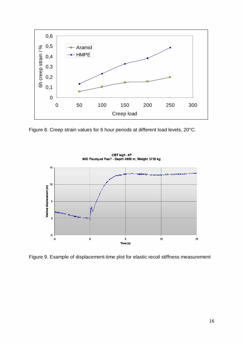
Following the stiffness measurements a creep-recovery sequence was applied. Creep, the extension of a rope under constant load, can be a concern for HMPE ropes subjected to high loads and/or high temperatures (Smeets et al 2001). The difficulty in characterizing creep is that long times may be necessary to stabilize it, and short term creep rates may be much higher than those measured over longer periods. However, as most handling operations last only a few hours the tests here were limited to a 6-hour constant load creep period followed by removing the load and a 6 hour recovery period before increasing the creep load to the next level. Figure 8 shows the measured creep strain values for the two materials, defined as the total increase in strain between reaching the creep load and the start of unloading. The creep strains are significantly lower for the aramid rope.
5. Stiffness measurements at sea In order to examine the behaviour of these materials under in-service conditions various measurements have been made on aramid and HMPE ropes on the Marion Dufresne, PourquoiPas, Suroît, and James Cook research vessels. These measurements were performed in calm sea by lowering the coring system to a given depth, then releasing a known weight, typically around 1 ton, with the trigger arm. The resulting vertical displacement of the cable, typically several meters, Figure 9, was calculated from the acceleration
5
measured by a sensor (NKE STPH transducer) fixed to the trigger arm. The measured strain rate, 0.05% per second, was a little higher than the rate imposed during laboratory bedding-in (0.025%/s). The apparent elastic modulus Eapp was then determined using the expression:
Eapp = (Ww.Lf)/(Lr.S)
with Ww the weight of the dropped mass in water, Lf the rope length, Lr the rebound distance, S the rope section. Table 4 shows some stiffness values measured on the different oceanographic vessels.
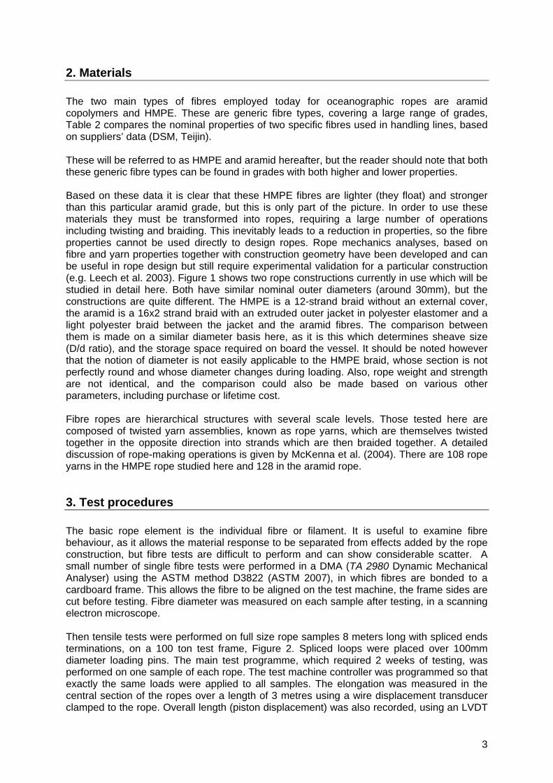
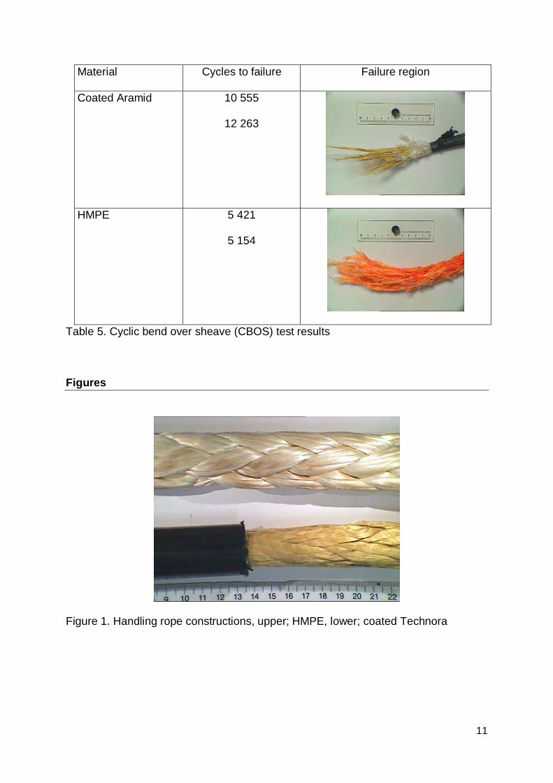
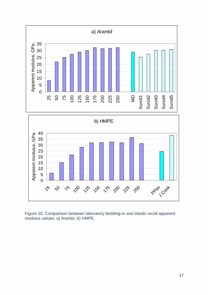
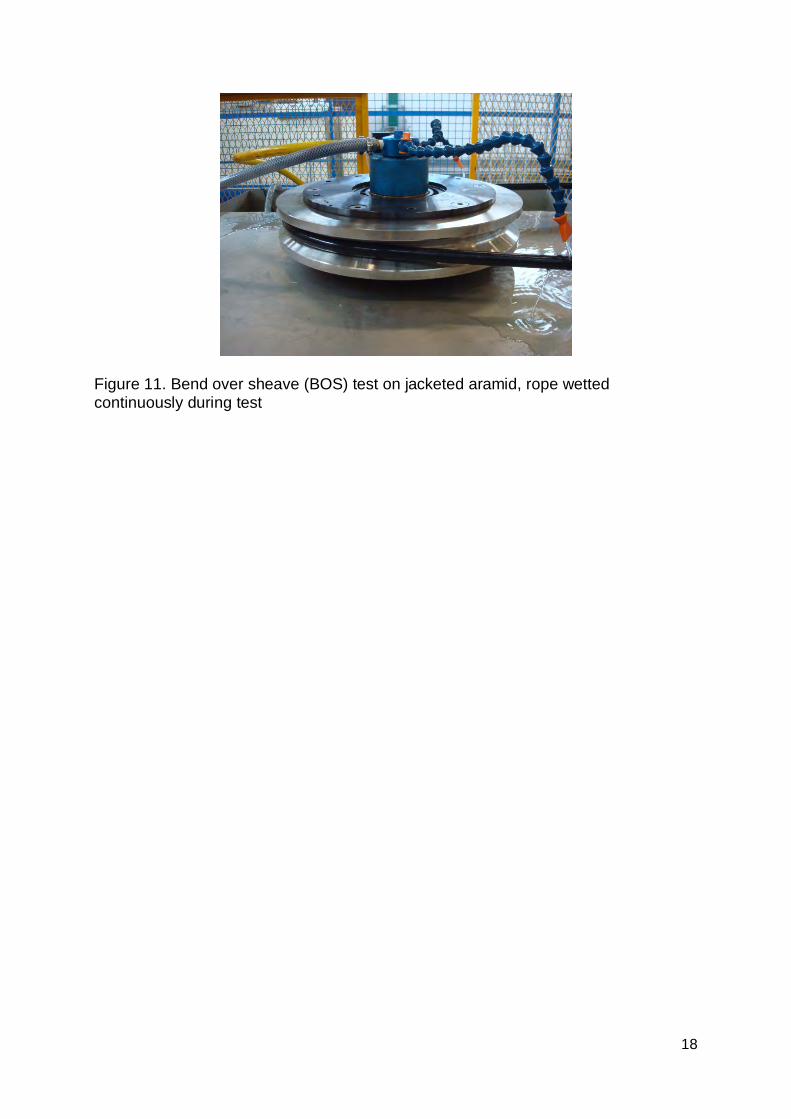
6. Discussion 6.1 Stiffness The results shown above clearly demonstrate that synthetic fibre rope stiffness properties are more complex than those of steel, and test conditions must be specified when stiffness values are cited. The initial stiffness of the HMPE rope is low but once bedding-in, which involves both fibre re-orientation and changes to the construction, has been achieved the dynamic stiffness potential is significantly higher for the HMPE than the aramid. This can be seen both in laboratory test results, Table 3, and by comparing new and heat treated rope values in Table 4. If we calculate apparent initial modulus values from the force/strain values measured in the laboratory, using the same nominal surface areas as those employed to obtain the values from elastic recoil stiffness, a comparison can be made, Figure 10. For both materials the apparent stiffnesses measured at sea are in the range of values measured in the laboratory during initial loading. The exact values will depend on the complete loading history of the rope, but it is clear from this Figure and the results in section 4.1 that for the aramid 80% of the bedded-in stiffness is obtained after loading to 15% of the break load, while for the HMPE it is necessary to load to about 20% MBL to reach this level. These loads are in the working range for piston coring. 6.2 Bending behaviour Other properties of interest for handling ropes are those characterizing the interaction of the rope with sheaves and winches. The performance of fibre ropes during repeated bending on winches and sheaves is very complex, depending on both internal and external friction. The oceanographic vessels use a high D/d (sheave diameter/rope diameter), typically over 50 to reduce wear, but it has been shown elsewhere (Derombise et al. 2008) that the standard aramid rope can degrade after repeated bending over sheaves. However, very few comparative data are available. In order to extend the direct comparison of the two rope options some smaller ropes, with the same aramid copolymer and HMPE fibres and constructions as the 29 mm diameter ropes but of smaller (18mm) diameter, were subjected to repeated cycling over a 380 mm diameter steel sheave, Figure 11. The sheave angle is 60°, with a groove diameter of 20.9 mm. This is a severe test, the D/d ratio is around 21, but it provides a first indication of the relative performance of the two materials. Samples were continuously wetted with tap water during tests. Table 5 shows the cycles to failure for tests on two samples of each material, with an applied load of 40 kN (20% of break load) in the rope and a cyclic displacement over the sheave of 400mm in 20 seconds.
6
All samples failed on the sheave. These data suggest that the aramid rope is better on sheaves than HMPE but this is only part of the picture. Tests on aramid copolymer ropes soaked in sea water before BOS testing showed reduced lifetimes (Derombise et al, 2008), consistent with the low lifetimes of aramid yarns in the yarn-on-yarn abrasion test. The performance of the aramid rope is therefore highly dependent on the extent to which the coating slows water ingress. These results indicate one aspect of the differences between the two ropes, which is governed by inter-strand abrasion within the rope. However, external friction coefficients between the rope and a winch drum are also important as they dimension the winch system, and those of HMPE tend to be rather low compared to the coated aramid coefficients. Finally, it should also be noted that there are many technological developments which can improve both bending fatigue behaviour and friction coefficients. These include external coatings, mixtures of fibres and improved fibre sizings e.g. [Nye and Longerich 2004]. This is a rapidly evolving area and several commercial alternatives are now available.
7. Conclusion This paper has presented results from mechanical tests on the two types of synthetic fibre ropes most used for deep sea handling operations, aramid and HMPE. Both ropes have advantages and disadvantages and both are currently in use on oceanographic vessels. The aramid rope stiffness is less sensitive to bedding-in and shows lower permanent residual strains. It also creeps less. The HMPE rope is lighter, and stiffer after bedding-in with higher damping. Cyclic loading on sheaves is superior for dry aramid but experience from tests on soaked aramid and in-service experience suggests that wet fatigue behaviour of aramid is not as good as that of wet HMPE. Measurements of apparent stiffness at sea appear consistent with laboratory values, but loading history and in particular the maximum load seen previously by the rope determine the apparent stiffness. In the past this has been a rather limited commercial activity, but the offshore oil and gas industry has recently become very interested in large deep sea handling ropes. As a result the market has expanded and considerable R&D effort is being applied to improvements in rope technology for these applications. This should also benefit future oceanographic applications.
References ASTM D3822 - 07 Standard Test Method for Tensile Properties of Single Textile Fibers, 2007. Brandes H, Geotechnical characteristics of deep sea sediments from the North Atlantic and North Pacific oceans, Ocean Engineering, 38 (2011) 835-848. Chailleux E, Davies P, Modelling the non-linear viscoelastic and viscoplastic behaviour of aramid fibre yarns, Mechanics of Time Dependent Materials, Vol 7, (2003), pp291-303. Del Vecchio CJM (1992), Light weight materials for deep water moorings, PhD thesis University of Reading, UK Derombise G, Davies P, van Schoors L, Dussud L, Durability of Aramid Ropes in a Marine Environment, Paper OMAE 2008-51799, Proceedings of the ASME 27th International Conference on Offshore; Mechanics and Arctic Engineering; June 15-20, (2008), Estoril, Portugal. DSM Technical brochure, Dyneema® in marine andindustrial applications
7
8
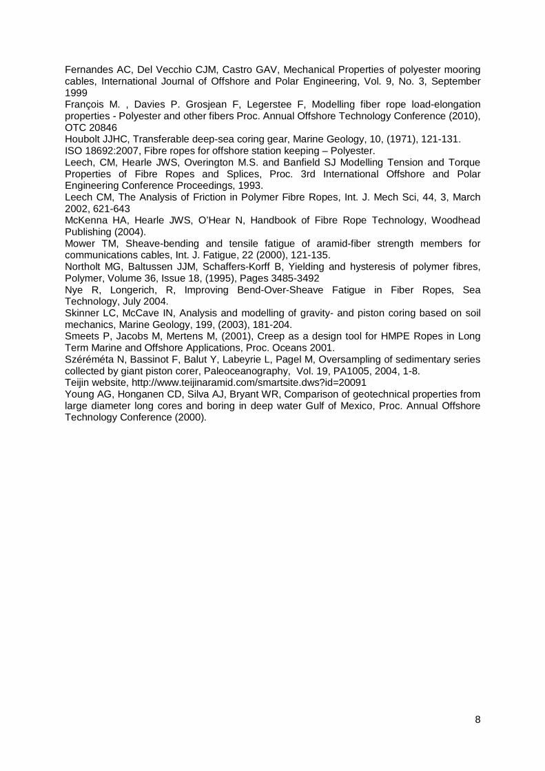
Fernandes AC, Del Vecchio CJM, Castro GAV, Mechanical Properties of polyester mooring cables, International Journal of Offshore and Polar Engineering, Vol. 9, No. 3, September 1999 François M. , Davies P. Grosjean F, Legerstee F, Modelling fiber rope load-elongation properties - Polyester and other fibers Proc. Annual Offshore Technology Conference (2010), OTC 20846 Houbolt JJHC, Transferable deep-sea coring gear, Marine Geology, 10, (1971), 121-131. ISO 18692:2007, Fibre ropes for offshore station keeping – Polyester. Leech, CM, Hearle JWS, Overington M.S. and Banfield SJ Modelling Tension and Torque Properties of Fibre Ropes and Splices, Proc. 3rd International Offshore and Polar Engineering Conference Proceedings, 1993. Leech CM, The Analysis of Friction in Polymer Fibre Ropes, Int. J. Mech Sci, 44, 3, March 2002, 621-643 McKenna HA, Hearle JWS, O’Hear N, Handbook of Fibre Rope Technology, Woodhead Publishing (2004). Mower TM, Sheave-bending and tensile fatigue of aramid-fiber strength members for communications cables, Int. J. Fatigue, 22 (2000), 121-135. Northolt MG, Baltussen JJM, Schaffers-Korff B, Yielding and hysteresis of polymer fibres, Polymer, Volume 36, Issue 18, (1995), Pages 3485-3492 Nye R, Longerich, R, Improving Bend-Over-Sheave Fatigue in Fiber Ropes, Sea Technology, July 2004. Skinner LC, McCave IN, Analysis and modelling of gravity- and piston coring based on soil mechanics, Marine Geology, 199, (2003), 181-204. Smeets P, Jacobs M, Mertens M, (2001), Creep as a design tool for HMPE Ropes in Long Term Marine and Offshore Applications, Proc. Oceans 2001. Széréméta N, Bassinot F, Balut Y, Labeyrie L, Pagel M, Oversampling of sedimentary series collected by giant piston corer, Paleoceanography, Vol. 19, PA1005, 2004, 1-8. Teijin website, http://www.teijinaramid.com/smartsite.dws?id=20091 Young AG, Honganen CD, Silva AJ, Bryant WR, Comparison of geotechnical properties from large diameter long cores and boring in deep water Gulf of Mexico, Proc. Annual Offshore Technology Conference (2000).
9
Tables
Vessel Operator Rope
Pelagia NIOZ, Holland Technora
RRS James Cook
RRS Discovery
NOC/NERC, UK
NOC/NERC, UK
HMPE
Aramid
RV Knorr WHOI, USA HMPE
Marion Dufresne IPEV, France Technora
PourquoiPas ?
Suroît
IFREMER, France
IFREMER, France
HMPE
Technora
Table 1. Synthetic fibre ropes used for deep sea oceanographic handling operations.
Fibre Reference Density Filament
diameter
µm
Modulus
GPa
Strength
MPa
HMPE Dyneema
SK75
0.98 18.5 109-132 3300-3900
Aramid Technora
T221
1.39 12.5 70 3000
Table 2. Nominal fibre properties
10
Stiffness value Aramid HMPE
End of bed-in (last 5 of 100
cycles)
200 292
Quasi-static (3 cycles) 166, 165, 168 201, 205, 210
Dynamic
Mean load (%MBL) / Amplitudes
50 (10%) /10, 23kN
100 (20%) /10, 23 kN
150 (30%) /10, 23 kN
200 (40%) /10, 23 kN
190,6 187,3
213,1 210,1
228,1 225,4
238,6 238,5
316,9 292,9
353,4 334,2
387,1 367,7
408,9 397,7
Table 3. Quasi-static and Dynamic stiffness measurements, kN/%, of bedded-in ropes.
Vessel Rope type Diameter, mm Measurement
depth, m
Apparent stiffness,
GPa
James Cook
Pourquoi Pas?
HMPE1
HMPE new
30
29
5260
4830
38
24.5
Marion Dufresne Suroît
Aramid
Aramid
302
172
4330
2660
28.9
28.8 (25.4 – 31.0)
Table 4. Stiffness values from elastic recoil measurements on oceanographic vessels.
1 Heat treated HMPE, 2 Diameter of outer jacket
11
Material Cycles to failure Failure region
Coated Aramid 10 555
12 263
HMPE 5 421
5 154
Table 5. Cyclic bend over sheave (CBOS) test results
Figures
Figure 1. Handling rope constructions, upper; HMPE, lower; coated Technora
12
Figure 2. Part of aramid rope on 100 ton test frame with wire transducer in place. Cover removed at rope ends for splicing.
a) b)
c) d) Figure 3. Test loading sequences a) Bedding-in b) Quasi-static stiffness c) Dynamic stiffness (increasing load part only shown, the complete cycle lasts 14 hours) d) Creep-recovery
0
50
100
150
200
250
300
0 0,5 1 1,5 2 2,5Time, h
For
ce,
kN
0
50
100
150
200
0 1 2 3 4Time, h
Fo
rce
, kN
0
50
100
150
200
250
0 2 4 6 8 10
Time, h
Fo
rce
, kN
0
50
100
150
200
250
300
0 10 20 30 40 50 60
Time, h
Fo
rce
, kN
13
a
b
(a) Figure 4. First loading cycles, a) single fibres, b) ropes
First loading, single fibre
0
200
400
600
800
1000
1200
1400
0 1 2 3 4 5
Strain, %
Nom
inal
str
ess,
MP
a .
First loading, new Ropes
0
50
100
150
200
250
300
0 1 2 3 4 5
Strain, %
Fo
rce
, kN
HMPE
Aramid
14
Figure 5. Residual strain versus maximum load during first loading cycles, fibre and rope. a) Aramid, b) HMPE
a) Aramid
0
1
2
0 20 40 60
% Break load
Re
sid
ua
l str
ain
, %
Fibre
Rope
b) HMPE
0
1
2
3
4
0 20 40 60
% Break load
Re
sid
ua
l str
ain
, %
Fibre
Rope
15
Figure 6. Cycling to stabilize rope stiffness at 10-30% MBL . Last 5 cycles (125 data points for each plot)
Figure 7. Influence of mean load on dynamic stiffness, showing values corresponding to increasing and decreasing mean load with amplitude ±2% MBL
Last 5 cycles
0
20
40
60
80
100
120
140
160
0 0,1 0,2 0,3 0,4 0,5
Strain, %
Fo
rce
, kN
HMPE
Aramid
Dynamic stiffness
050
100150200250300350400450
0 50 100 150 200 250
Mean load
Stif
fne
ss,
kN/%
HMPE
Aramid
16
Figure 8. Creep strain values for 6 hour periods at different load levels, 20°C.
Figure 9. Example of displacement-time plot for elastic recoil stiffness measurement
0
0,1
0,2
0,3
0,4
0,5
0,6
0 50 100 150 200 250 300
Creep load
6h
cre
ep
str
ain
/ % Aramid
HMPE
17
Figure 10. Comparison between laboratory bedding-in and elastic recoil apparent modulus values. a) Aramid, b) HMPE.
a) Aramid
0
5
10
15
20
25
30
352
5
50
75
10
0
12
5
15
0
17
5
20
0
22
5
25
0
MD
Su
roit1
Su
roit2
Su
roit3
Su
roit4
Su
roit5
Ap
pa
ren
t mo
du
lus,
GP
a.
b) HMPE
05
10152025303540
25 50 75 100
125
150
175
200
225
250
PPas
J Coo
k
Ap
pa
ren
t mo
du
lus,
GP
a.
18
Figure 11. Bend over sheave (BOS) test on jacketed aramid, rope wetted continuously during test