Embed Size (px)
Citation preview
Mechanical characterization of a dielectric elastomer microactuator with ion-implanted electrodes
S. Rosset, M. Niklaus, P. Dubois, H.R. Shea
The following document is a post-print of the article published in Sensors and Actuators A 144 (2008) 185–193. The original article can be accessed at http://dx.doi.org/10.1016/j.sna.2007.12.030
Mechanical Characterization of a Dielectric
Elastomer Microactuator With Ion-Implanted
Electrodes
S. Rosset ∗, M. Niklaus, P. Dubois, H. R. Shea
Microsystems for Space Technologies Laboratory, Ecole Polytechnique Federale de
Lausanne, Switzerland
Abstract
We report on the mechanical characterization and modeling of a non-prestretcheddielectric elastomer diaphragm microactuator with ion-implanted electrodes underthe influence of a distributed load (pressure). Thin PDMS membranes (30 µm thick,2-3 mm diameter) were implanted on both side with gold ions by Filtered CathodicVacuum Arc and bonded on silicon chips with through-holes. A voltage appliedbetween the implanted electrodes creates a compressive stress in the dielectric andcauses the membrane to buckle and form a bump whose height depends on the me-chanical properties of the electroactive compound, the voltage and the force appliedon the membrane. Maximum unloaded displacements up to 7% of the membrane’slateral dimensions were achieved, which was reduced to 3% when a distributed forceof 1 kPa was applied on the membrane. The maximum mechanical work obtainedby the actuators is in the range of 0.3 µJ. An analytical model was developped tocalculate the displacement of the DEAs based on their mechanical and geometricalproperties, voltage and applied force. The model shows very good agreement withthe measurements and allows accurate performance prediction and dimensioning ofsuch actuators.
Key words: Dielectric Electroactive Polymer Actuators, Ion Implantation,Electrostatic Actuation, Membrane, Artificial Muscles, DEAP
∗ Corresponding author: rue Jaquet-Droz 1, cp 526, 2002 Neuchatel, SwitzerlandEmail address: [email protected] (S. Rosset).
Preprint submitted to Elsevier 23 November 2007
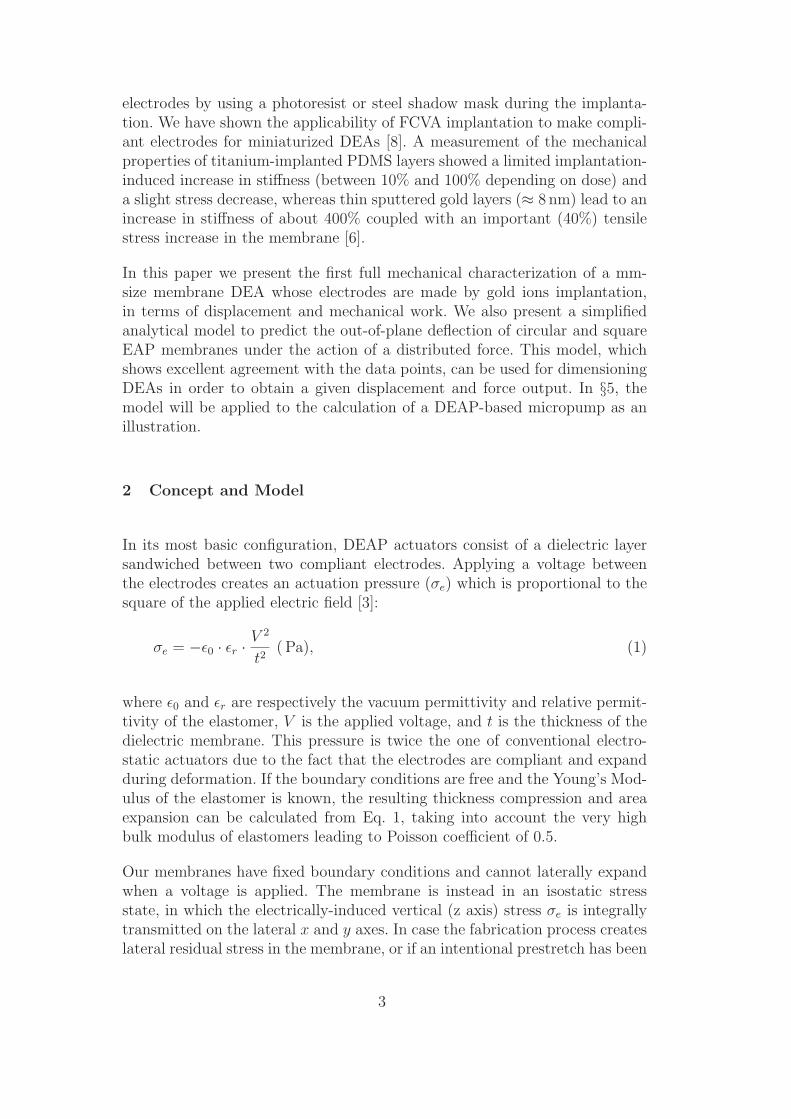
Fig. 1. Dielectric EAP (DEAP) principle. When a voltage is applied to the electrodes(typically up to 1 kV), the electrostatic pressure squeezes the elastomer dielectric(right side). The volume of the dielectric being quasi constant, the whole structurestretches in the case of free boundary conditions (from [6]).
1 Introduction
Electroactive Polymers (EAPs) actuators have attracted wide interest for thelast 15 years due to their large strain capabilities (up to several hundred per-cents) coupled with reasonable output actuation pressure (about 1 kPa) andlow density (ρ ≈ 1000 kg/m3), which gives them properties similar to thoseof natural muscles [1]. Among the two main classes of EAPs (Electronic andIonic [2]), Dielectric Elastomer Actuators (DEAs) have the advantage of be-ing electrostatically driven: they are low-power actuators, require no power tohold a position and have a relatively fast response time. DEAs consist of asoft dielectric (typically Polydimethysiloxane (PDMS) or Acrylic) sandwichedbetween two conductive and compliant electrodes. When a voltage is appliedbetween the electrodes, a compressive stress is generated inside the dielectricwhich is squeezed. As elastomers keep their volume constant during deforma-tion (Poisson coefficient close to 0.5), the thickness’ decrease causes the surfaceto expand in the case of free boundary conditions (Fig. 1). Most of the time,electrodes are made a) with carbon powder mixed with unpolymerized elas-tomer or sprayed onto the cured polymer, b) with carbon grease applied witha paintbrush, or c) with conducting polymers [3–5]. This is a major drawbackfor the miniaturization of DEAs due to the impossibility to pattern micron-scale conductive electrodes and the incompatibility of carbon particles witha clean-room environment. Attempts to use conventional thin-film depositionmethods (sputtering, evaporation) leads to a dramatic decrease of performancedue to the stiffening of the structure caused by the high Young’s Moduli ofmetals compared to that of elastomer (up to five orders of magnitude) [6,7].
We use low energy Filtered Cathodic Vacuum Arc (FCVA) metal ion implan-tation to create compliant electrodes at the surface of the PDMS. This createsa conductive layer in the first few nanometers of the PDMS’ surface, withoutstiffening it too much. This technique can easily be used to make patterned
2
electrodes by using a photoresist or steel shadow mask during the implanta-tion. We have shown the applicability of FCVA implantation to make compli-ant electrodes for miniaturized DEAs [8]. A measurement of the mechanicalproperties of titanium-implanted PDMS layers showed a limited implantation-induced increase in stiffness (between 10% and 100% depending on dose) anda slight stress decrease, whereas thin sputtered gold layers (≈ 8 nm) lead to anincrease in stiffness of about 400% coupled with an important (40%) tensilestress increase in the membrane [6].
In this paper we present the first full mechanical characterization of a mm-size membrane DEA whose electrodes are made by gold ions implantation,in terms of displacement and mechanical work. We also present a simplifiedanalytical model to predict the out-of-plane deflection of circular and squareEAP membranes under the action of a distributed force. This model, whichshows excellent agreement with the data points, can be used for dimensioningDEAs in order to obtain a given displacement and force output. In §5, themodel will be applied to the calculation of a DEAP-based micropump as anillustration.
2 Concept and Model
In its most basic configuration, DEAP actuators consist of a dielectric layersandwiched between two compliant electrodes. Applying a voltage betweenthe electrodes creates an actuation pressure (σe) which is proportional to thesquare of the applied electric field [3]:
σe = −ǫ0 · ǫr ·V 2
t2( Pa), (1)
where ǫ0 and ǫr are respectively the vacuum permittivity and relative permit-tivity of the elastomer, V is the applied voltage, and t is the thickness of thedielectric membrane. This pressure is twice the one of conventional electro-static actuators due to the fact that the electrodes are compliant and expandduring deformation. If the boundary conditions are free and the Young’s Mod-ulus of the elastomer is known, the resulting thickness compression and areaexpansion can be calculated from Eq. 1, taking into account the very highbulk modulus of elastomers leading to Poisson coefficient of 0.5.
Our membranes have fixed boundary conditions and cannot laterally expandwhen a voltage is applied. The membrane is instead in an isostatic stressstate, in which the electrically-induced vertical (z axis) stress σe is integrallytransmitted on the lateral x and y axes. In case the fabrication process createslateral residual stress in the membrane, or if an intentional prestretch has been
3
applied, the electrostatic pressure adds to the residual stress in the x and ydirections [9]:
σz = σe = −ǫ0 · ǫr ·V 2
t2
σx = σy = σ0 + σe = σ0 − ǫ0 · ǫr ·V 2
t2, (2)
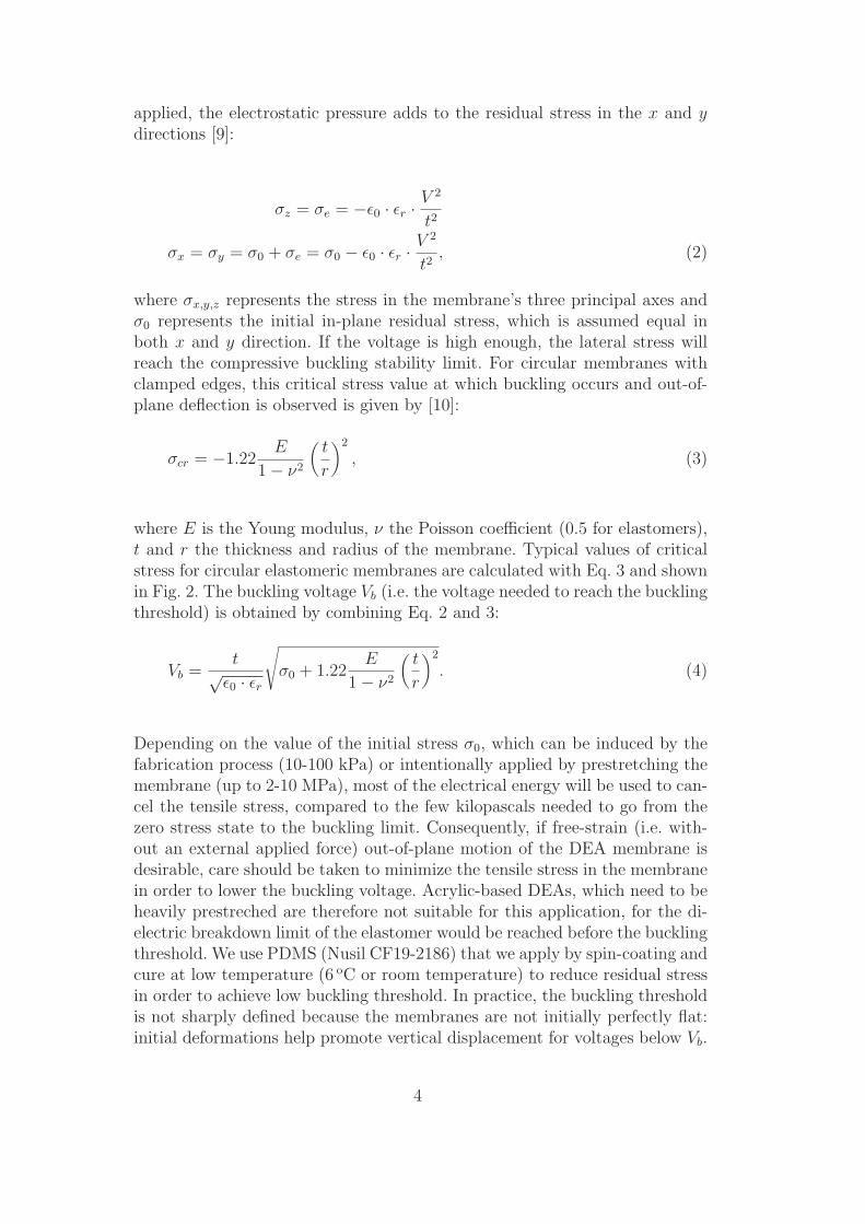
where σx,y,z represents the stress in the membrane’s three principal axes andσ0 represents the initial in-plane residual stress, which is assumed equal inboth x and y direction. If the voltage is high enough, the lateral stress willreach the compressive buckling stability limit. For circular membranes withclamped edges, this critical stress value at which buckling occurs and out-of-plane deflection is observed is given by [10]:
σcr = −1.22E
1 − ν2
(
t
r
)2
, (3)
where E is the Young modulus, ν the Poisson coefficient (0.5 for elastomers),t and r the thickness and radius of the membrane. Typical values of criticalstress for circular elastomeric membranes are calculated with Eq. 3 and shownin Fig. 2. The buckling voltage Vb (i.e. the voltage needed to reach the bucklingthreshold) is obtained by combining Eq. 2 and 3:
Vb =t
√ǫ0 · ǫr
√
σ0 + 1.22E
1 − ν2
(
t
r
)2
. (4)
Depending on the value of the initial stress σ0, which can be induced by thefabrication process (10-100 kPa) or intentionally applied by prestretching themembrane (up to 2-10 MPa), most of the electrical energy will be used to can-cel the tensile stress, compared to the few kilopascals needed to go from thezero stress state to the buckling limit. Consequently, if free-strain (i.e. with-out an external applied force) out-of-plane motion of the DEA membrane isdesirable, care should be taken to minimize the tensile stress in the membranein order to lower the buckling voltage. Acrylic-based DEAs, which need to beheavily prestreched are therefore not suitable for this application, for the di-electric breakdown limit of the elastomer would be reached before the bucklingthreshold. We use PDMS (Nusil CF19-2186) that we apply by spin-coating andcure at low temperature (6 oC or room temperature) to reduce residual stressin order to achieve low buckling threshold. In practice, the buckling thresholdis not sharply defined because the membranes are not initially perfectly flat:initial deformations help promote vertical displacement for voltages below Vb.
4
200 400 600 800 1000 1200 1400 160015
20
25
30
35
40
45
50
-20
kPa
-10
kPa
-5 k
Pa
-3 k
Pa
-2 kP
a
-1 kP
a
-0.6 kPa
-0.3 kPa
Thic
knes
s (
m)
Radius ( m)
-0.15 kPa
Fig. 2. Calculated critical buckling stress for circular membranes of different radiusand thickness for an elastomer with E=0.5 MPa, and a Poisson coefficient of 0.5
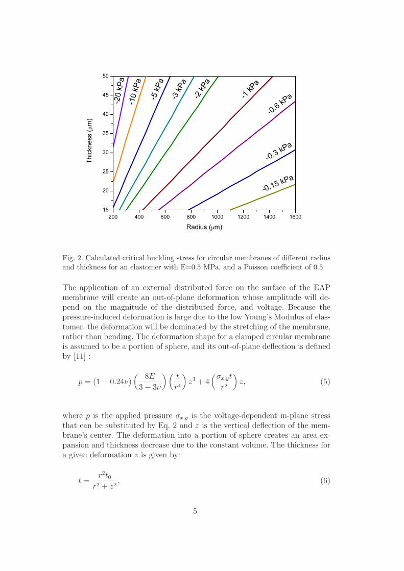
The application of an external distributed force on the surface of the EAPmembrane will create an out-of-plane deformation whose amplitude will de-pend on the magnitude of the distributed force, and voltage. Because thepressure-induced deformation is large due to the low Young’s Modulus of elas-tomer, the deformation will be dominated by the stretching of the membrane,rather than bending. The deformation shape for a clamped circular membraneis assumed to be a portion of sphere, and its out-of-plane deflection is definedby [11] :
p = (1 − 0.24ν)(
8E
3 − 3ν
) (
t
r4
)
z3 + 4(
σx,yt
r2
)
z, (5)
where p is the applied pressure σx,y is the voltage-dependent in-plane stressthat can be substituted by Eq. 2 and z is the vertical deflection of the mem-brane’s center. The deformation into a portion of sphere creates an area ex-pansion and thickness decrease due to the constant volume. The thickness fora given deformation z is given by:
t =r2t0
r2 + z2, (6)
5
0 20 40 60 80 1000
100
200
300
400
500
600
700
z0
z2Pre
ssur
e (P
a)
Bulge height ( m)
0V 0<V1<Vb
V2>Vb
z1
Fig. 3. Calculated pressure-deflection characteristics for three different applied volt-ages and illustration of the evolution of the equilibrium position for a selectedpressure of 100 Pa.
where t0 is the initial membrane thickness before deformation. This equationcan be substituted into Eq. 5 to take into account the thickness reductioncaused by membrane deformation.
Equation 5 does not take into account the hyper-elastic non-linear characteris-tics of elastomers and assumes a purely Hookean behavior. However, uniaxialcompression tests conducted on macroscale PDMS cylinders exhibited a lin-ear behavior for strains up to 10-20% [8]. In our application, the maximalpressure- and voltage-induced vertical deformation applied to the actuatorwas up to 15% of its diameter, which correspond to a surface strain of 8.3% atmost. Hence, these relatively small strains justifiy using a linear stress-strainrelation to model our actuators’ behavior.
Without any voltage applied, Eq. 5 is the bulge test equation. The bulge test isa well known technique to extract mechanical parameters (Young’s Modulusand residual stress) from thin film membranes by applying a pressure on oneside of the membrane and recording its deflection [11–13]. We have adaptedthis technique to soft polymer membranes and have used it to extract the me-chanical data of our DEAs [6]. By applying a voltage between the compliantelectrodes, the equilibrium position is modified as shown in Fig. 3 for threedifferent applied voltages: 1) 0 V; this is the calculated equilibrium point for a
6
membrane representative of our samples with an applied pressure on one side.When a pressure of 100 Pa is applied to this membrane, it will be deformedby 20 µm to reach the equilibrium z0. 2) When a voltage is applied the stressstate inside the membrane is modified and the deformation for a given pressureis increased by ∆z1. 3) If the Voltage is further increased, above the bucklingvoltage (Vb), the equilibrium position moves to z0 + ∆z2. In that case, a de-formation is observed even without pressure applied to the membrane. Usingthe geometrical and mechanical properties of an EAP membrane, Eq. 5 cantherefore be used to calculate the expected displacement for every values ofdistributed load and voltage, or inversely, given a desired output displacementfor a loading pressure, the equation can be used to find the mechanical andgeometrical parameters needed to meet the expected performance. A similarequation can be derived from the bulge test equation for square membranesof side a [13]:
p =1
0.792 + 0.085ν
Et
(1 − ν)(a/2)4z3 + 3.393
σx,yt
(a/2)2z. (7)
From the equation linking the deflection to the applied pressure, one cancalculate the displacement from the equilibrium position ∆z which is causedby the electrostatic force simply by removing the pressure-induced deformationz0 (Fig. 3):
∆z(p, V ) = z(p, V ) − z(p, 0), (8)
where z(p, V ) is the reciprocal function of Eq. 5 or 7. Finally, the mechanicalwork W is calculated by integrating over the surface the displacement z ofeach surface element dS multiplied by the distributed force p:
W =
z0∫
z0+∆z
z(p, V ) · p · dS. (9)
For circular membranes, and with the hypothesis of deformation in a portionof sphere, it is defined by:
W =p · π · ∆z(∆z2 + 3∆z · z0 + 3(r2 + z2
0))
6. (10)
The maximal voltage that can be applied to the actuator is limited by thedielectric breakdown of the elastomer, which varies between 35 and 50 V/µmfor our membranes with ion-implanted electrodes. The maximal distributedforce (pressure) is limited by the rupture point of the PDMS, which typically
7
occurs for elongations between 400% and 650%. The membranes can be in-flated in the shape of half-spheres without breaking. This corresponds to apressure of approximately 30 kPa. However the simple model presented herecannot be applied for such high pressures/deformations at which the hyper-elastic behavior of PDMS cannot be neglected. More complete models havebeen developed for this situation or for highly prestreched membranes [14].
3 Fabrication Process and Characterization
3.1 Fabrication of Freestanding Membranes
Samples consist of 30 µm-thick PDMS layers bonded on silicon (Si) chips withcircular and square through-holes of lateral dimension 2 to 3 mm. Both sidesof the membrane are implanted at 5 keV with Au ions with doses in the rangeof 1 − 2 · 1016 atoms/cm−2.
PDMS (Nusil CF19-2186) is mixed with isooctane to lower its viscosity andspin-coated on a flexible polyvinylidene chloride (PVDC) sheet coated with aphotoresist sacrificial layer, which allows easy bonding on a silicon wafer. ThePDMS is then cured at at room temperature or at 6 oC during 48 hours tominimize residual tensile stress, which is very sensitive to curing conditions[6]. Circular and square through-holes of lateral dimensions 2 to 3 mm arepatterned with DRIE on a 4” silicon wafer. The cured PDMS layer is thenbonded on the patterned silicon wafer after an oxygen plasma treatment. Theassembly is then dipped into acetone to dissolve the sacrificial layer and removethe PVDC transfer substrate. The wafers are diced into chips of 20×20 mm2.Resulting membranes have a Young’s Modulus of 0.5-0.6 MPa, a thickness of22 − 30 µm and a residual tensile stress of 10–40 kPa.
3.2 Implantation
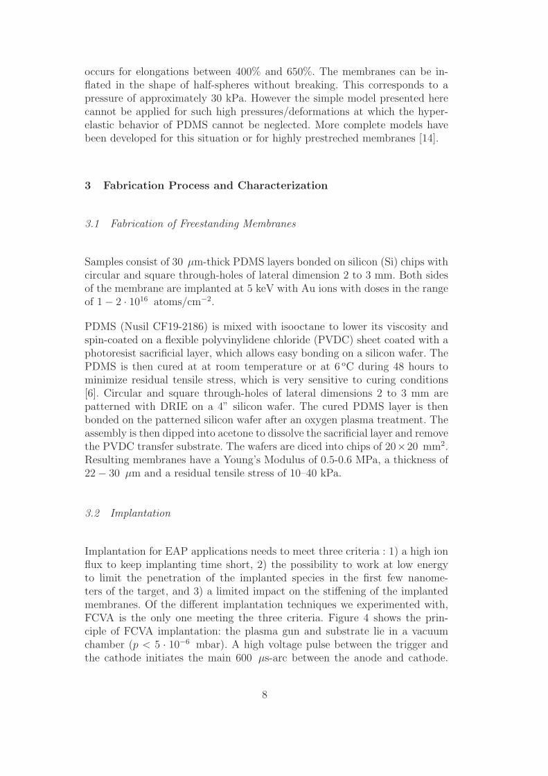
Implantation for EAP applications needs to meet three criteria : 1) a high ionflux to keep implanting time short, 2) the possibility to work at low energyto limit the penetration of the implanted species in the first few nanome-ters of the target, and 3) a limited impact on the stiffening of the implantedmembranes. Of the different implantation techniques we experimented with,FCVA is the only one meeting the three criteria. Figure 4 shows the prin-ciple of FCVA implantation: the plasma gun and substrate lie in a vacuumchamber (p < 5 · 10−6 mbar). A high voltage pulse between the trigger andthe cathode initiates the main 600 µs-arc between the anode and cathode.
8
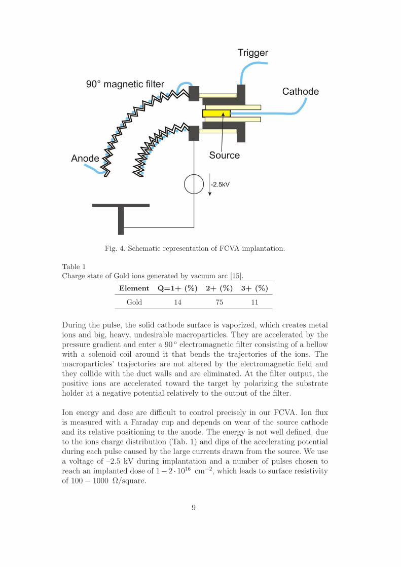
Fig. 4. Schematic representation of FCVA implantation.
Table 1Charge state of Gold ions generated by vacuum arc [15].
Element Q=1+ (%) 2+ (%) 3+ (%)
Gold 14 75 11
During the pulse, the solid cathode surface is vaporized, which creates metalions and big, heavy, undesirable macroparticles. They are accelerated by thepressure gradient and enter a 90 o electromagnetic filter consisting of a bellowwith a solenoid coil around it that bends the trajectories of the ions. Themacroparticles’ trajectories are not altered by the electromagnetic field andthey collide with the duct walls and are eliminated. At the filter output, thepositive ions are accelerated toward the target by polarizing the substrateholder at a negative potential relatively to the output of the filter.
Ion energy and dose are difficult to control precisely in our FCVA. Ion fluxis measured with a Faraday cup and depends on wear of the source cathodeand its relative positioning to the anode. The energy is not well defined, dueto the ions charge distribution (Tab. 1) and dips of the accelerating potentialduring each pulse caused by the large currents drawn from the source. We usea voltage of –2.5 kV during implantation and a number of pulses chosen toreach an implanted dose of 1− 2 · 1016 cm−2, which leads to surface resistivityof 100 − 1000 Ω/square.
9
Fig. 5. Left: topside implantation through a shadow mask (top), and backside im-plantation through the openings in the Si chip (bottom). Right: complete chip withgold pads for electrical contacts.
Topside implantation is conducted through a steel shadow mask to defineseveral independent devices on a single chip. Patterned photoresist can alsobe used as a mask for implantation if better resolution is needed. Backsideimplantation is directly conducted through the opening in the silicon chip.An electrical contact is created by the ions between the membrane and thesilicon frame, which can act as the backside electrical connection (Fig. 5). Asputtered gold pad is also deposited on the surface of the implanted PDMSclose to each membrane to provide the top electrical contact.
4 Measurements and Results
4.1 Mechanical properties
The mechanical properties are measured on a bulge test setup. The chip withthe implanted membranes is mounted on an airtight socket and placed underan optical profiler (Wyko NT1100 from Veeco). A syringe pump is connected tothe socket via a large (300 ml) buffer volume. A barometric sensor (IntersemaMS5537) with 1 Pa resolution is connected to the circuit to measure the appliedpressure, which is varied from 0 to 1 kPa by steps of 15 Pa. For each pressurestep, the central deflection is measured with the profiler, which allows theextraction of the Young’s Modulus and residual stress according to Eq. 5 orEq. 7. These two parameters can then be used to calculate the membrane’s
10
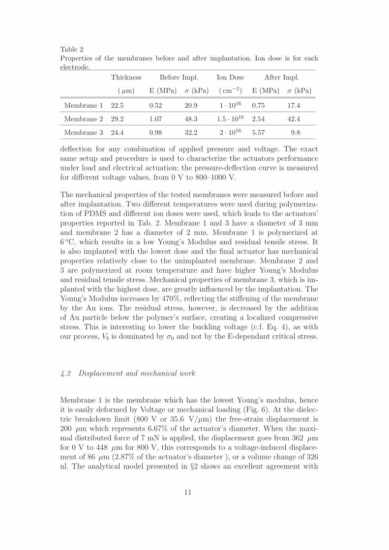
Table 2Properties of the membranes before and after implantation. Ion dose is for eachelectrode.
Thickness Before Impl. Ion Dose After Impl.
(µm) E (MPa) σ (kPa) ( cm−2) E (MPa) σ (kPa)
Membrane 1 22.5 0.52 20.9 1 · 1016 0.75 17.4
Membrane 2 29.2 1.07 48.3 1.5 · 1016 2.54 42.4
Membrane 3 24.4 0.98 32.2 2 · 1016 5.57 9.8
deflection for any combination of applied pressure and voltage. The exactsame setup and procedure is used to characterize the actuators performanceunder load and electrical actuation: the pressure-deflection curve is measuredfor different voltage values, from 0 V to 800–1000 V.
The mechanical properties of the tested membranes were measured before andafter implantation. Two different temperatures were used during polymeriza-tion of PDMS and different ion doses were used, which leads to the actuators’properties reported in Tab. 2. Membrane 1 and 3 have a diameter of 3 mmand membrane 2 has a diameter of 2 mm. Membrane 1 is polymerized at6 oC, which results in a low Young’s Modulus and residual tensile stress. Itis also implanted with the lowest dose and the final actuator has mechanicalproperties relatively close to the unimplanted membrane. Membrane 2 and3 are polymerized at room temperature and have higher Young’s Modulusand residual tensile stress. Mechanical properties of membrane 3, which is im-planted with the highest dose, are greatly influenced by the implantation. TheYoung’s Modulus increases by 470%, reflecting the stiffening of the membraneby the Au ions. The residual stress, however, is decreased by the additionof Au particle below the polymer’s surface, creating a localized compressivestress. This is interesting to lower the buckling voltage (c.f. Eq. 4), as withour process, Vb is dominated by σ0 and not by the E-dependant critical stress.
4.2 Displacement and mechanical work
Membrane 1 is the membrane which has the lowest Young’s modulus, henceit is easily deformed by Voltage or mechanical loading (Fig. 6). At the dielec-tric breakdown limit (800 V or 35.6 V/µm) the free-strain displacement is200 µm which represents 6.67% of the actuator’s diameter. When the maxi-mal distributed force of 7 mN is applied, the displacement goes from 362 µmfor 0 V to 448 µm for 800 V, this corresponds to a voltage-induced displace-ment of 86 µm (2.87% of the actuator’s diameter ), or a volume change of 326nl. The analytical model presented in §2 shows an excellent agreement with
11
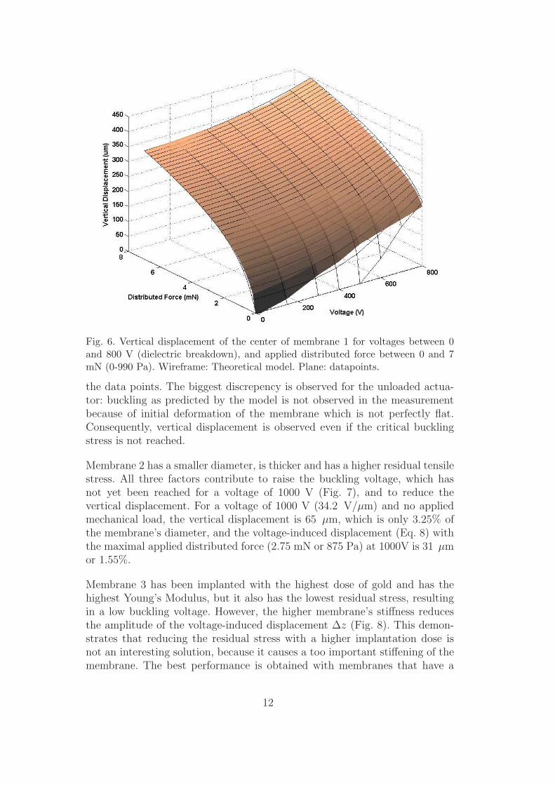
Fig. 6. Vertical displacement of the center of membrane 1 for voltages between 0and 800 V (dielectric breakdown), and applied distributed force between 0 and 7mN (0-990 Pa). Wireframe: Theoretical model. Plane: datapoints.
the data points. The biggest discrepency is observed for the unloaded actua-tor: buckling as predicted by the model is not observed in the measurementbecause of initial deformation of the membrane which is not perfectly flat.Consequently, vertical displacement is observed even if the critical bucklingstress is not reached.
Membrane 2 has a smaller diameter, is thicker and has a higher residual tensilestress. All three factors contribute to raise the buckling voltage, which hasnot yet been reached for a voltage of 1000 V (Fig. 7), and to reduce thevertical displacement. For a voltage of 1000 V (34.2 V/µm) and no appliedmechanical load, the vertical displacement is 65 µm, which is only 3.25% ofthe membrane’s diameter, and the voltage-induced displacement (Eq. 8) withthe maximal applied distributed force (2.75 mN or 875 Pa) at 1000V is 31 µmor 1.55%.
Membrane 3 has been implanted with the highest dose of gold and has thehighest Young’s Modulus, but it also has the lowest residual stress, resultingin a low buckling voltage. However, the higher membrane’s stiffness reducesthe amplitude of the voltage-induced displacement ∆z (Fig. 8). This demon-strates that reducing the residual stress with a higher implantation dose isnot an interesting solution, because it causes a too important stiffening of themembrane. The best performance is obtained with membranes that have a
12
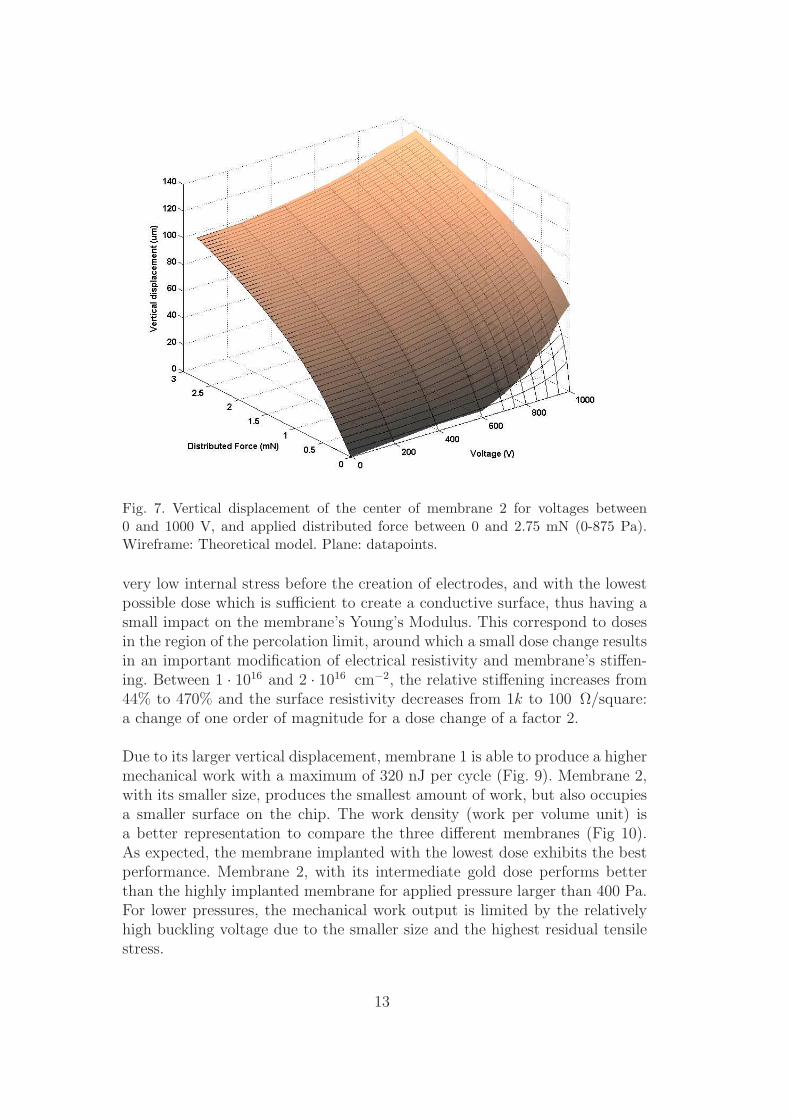
Fig. 7. Vertical displacement of the center of membrane 2 for voltages between0 and 1000 V, and applied distributed force between 0 and 2.75 mN (0-875 Pa).Wireframe: Theoretical model. Plane: datapoints.
very low internal stress before the creation of electrodes, and with the lowestpossible dose which is sufficient to create a conductive surface, thus having asmall impact on the membrane’s Young’s Modulus. This correspond to dosesin the region of the percolation limit, around which a small dose change resultsin an important modification of electrical resistivity and membrane’s stiffen-ing. Between 1 · 1016 and 2 · 1016 cm−2, the relative stiffening increases from44% to 470% and the surface resistivity decreases from 1k to 100 Ω/square:a change of one order of magnitude for a dose change of a factor 2.
Due to its larger vertical displacement, membrane 1 is able to produce a highermechanical work with a maximum of 320 nJ per cycle (Fig. 9). Membrane 2,with its smaller size, produces the smallest amount of work, but also occupiesa smaller surface on the chip. The work density (work per volume unit) isa better representation to compare the three different membranes (Fig 10).As expected, the membrane implanted with the lowest dose exhibits the bestperformance. Membrane 2, with its intermediate gold dose performs betterthan the highly implanted membrane for applied pressure larger than 400 Pa.For lower pressures, the mechanical work output is limited by the relativelyhigh buckling voltage due to the smaller size and the highest residual tensilestress.
13
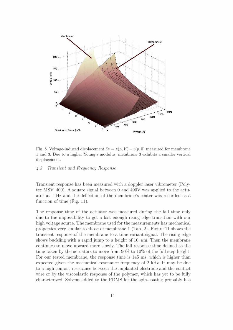
Fig. 8. Voltage-induced displacement δz = z(p, V )−z(p, 0) measured for membrane1 and 3. Due to a higher Young’s modulus, membrane 3 exhibits a smaller verticaldisplacement.
4.3 Transient and Frequency Response
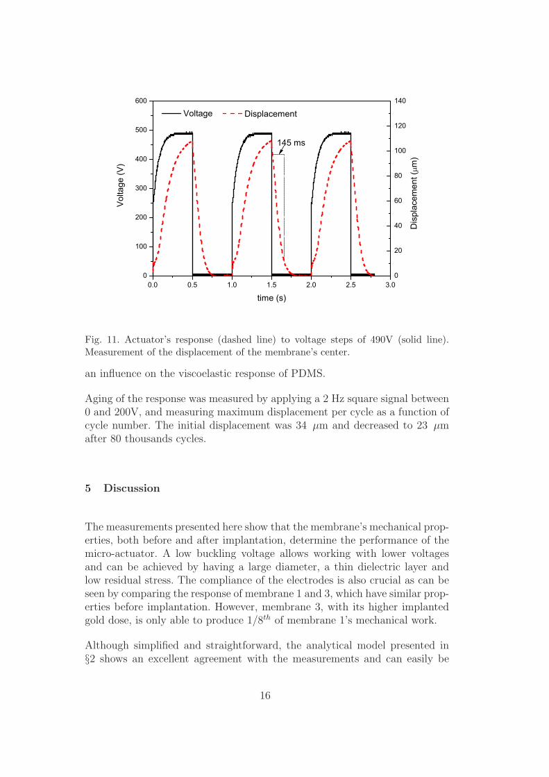
Transient response has been measured with a doppler laser vibrometer (Poly-tec MSV–400). A square signal between 0 and 490V was applied to the actu-ator at 1 Hz and the deflection of the membrane’s center was recorded as afunction of time (Fig. 11).
The response time of the actuator was measured during the fall time onlydue to the impossibility to get a fast enough rising edge transition with ourhigh voltage source. The membrane used for the measurements has mechanicalproperties very similar to those of membrane 1 (Tab. 2). Figure 11 shows thetransient response of the membrane to a time-variant signal. The rising edgeshows buckling with a rapid jump to a height of 10 µm. Then the membranecontinues to move upward more slowly. The fall response time defined as thetime taken by the actuators to move from 90% to 10% of the full step height.For our tested membrane, the response time is 145 ms, which is higher thanexpected given the mechanical resonance frequency of 2 kHz. It may be dueto a high contact resistance between the implanted electrode and the contactwire or by the viscoelastic response of the polymer, which has yet to be fullycharacterized. Solvent added to the PDMS for the spin-coating propably has
14
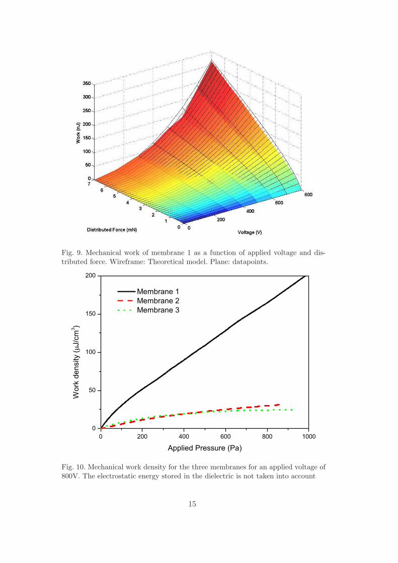
Fig. 9. Mechanical work of membrane 1 as a function of applied voltage and dis-tributed force. Wireframe: Theoretical model. Plane: datapoints.
0 200 400 600 800 10000
50
100
150
200
Wor
k de
nsity
(J/
cm3 )
Applied Pressure (Pa)
Membrane 1 Membrane 2 Membrane 3
Fig. 10. Mechanical work density for the three membranes for an applied voltage of800V. The electrostatic energy stored in the dielectric is not taken into account
15
0.0 0.5 1.0 1.5 2.0 2.5 3.00
100
200
300
400
500
600
0
20
40
60
80
100
120
140
VoltageV
olta
ge (V
)
time (s)
Displacement
Dis
plac
emen
t (m
)
145 ms
Fig. 11. Actuator’s response (dashed line) to voltage steps of 490V (solid line).Measurement of the displacement of the membrane’s center.
an influence on the viscoelastic response of PDMS.
Aging of the response was measured by applying a 2 Hz square signal between0 and 200V, and measuring maximum displacement per cycle as a function ofcycle number. The initial displacement was 34 µm and decreased to 23 µmafter 80 thousands cycles.
5 Discussion
The measurements presented here show that the membrane’s mechanical prop-erties, both before and after implantation, determine the performance of themicro-actuator. A low buckling voltage allows working with lower voltagesand can be achieved by having a large diameter, a thin dielectric layer andlow residual stress. The compliance of the electrodes is also crucial as can beseen by comparing the response of membrane 1 and 3, which have similar prop-erties before implantation. However, membrane 3, with its higher implantedgold dose, is only able to produce 1/8th of membrane 1’s mechanical work.
Although simplified and straightforward, the analytical model presented in§2 shows an excellent agreement with the measurements and can easily be
16
800 1000 1200 1400 16000
200
400
600
800
1000
1200
1400
1600
600 Pa
4
3
2
Pre
ssur
e (P
a)
Volume (nl)
800 V
0 V
1
841 Pa
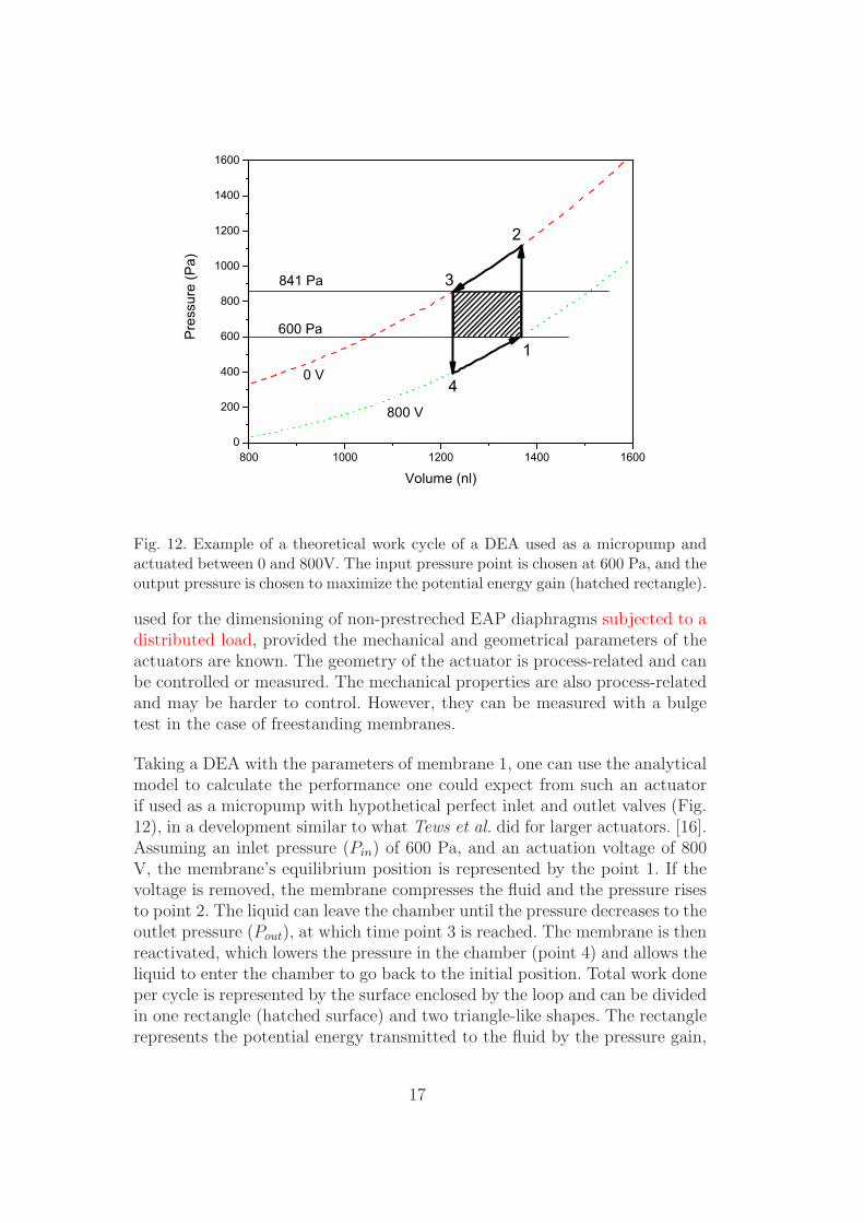
Fig. 12. Example of a theoretical work cycle of a DEA used as a micropump andactuated between 0 and 800V. The input pressure point is chosen at 600 Pa, and theoutput pressure is chosen to maximize the potential energy gain (hatched rectangle).
used for the dimensioning of non-prestreched EAP diaphragms subjected to adistributed load, provided the mechanical and geometrical parameters of theactuators are known. The geometry of the actuator is process-related and canbe controlled or measured. The mechanical properties are also process-relatedand may be harder to control. However, they can be measured with a bulgetest in the case of freestanding membranes.
Taking a DEA with the parameters of membrane 1, one can use the analyticalmodel to calculate the performance one could expect from such an actuatorif used as a micropump with hypothetical perfect inlet and outlet valves (Fig.12), in a development similar to what Tews et al. did for larger actuators. [16].Assuming an inlet pressure (Pin) of 600 Pa, and an actuation voltage of 800V, the membrane’s equilibrium position is represented by the point 1. If thevoltage is removed, the membrane compresses the fluid and the pressure risesto point 2. The liquid can leave the chamber until the pressure decreases to theoutlet pressure (Pout), at which time point 3 is reached. The membrane is thenreactivated, which lowers the pressure in the chamber (point 4) and allows theliquid to enter the chamber to go back to the initial position. Total work doneper cycle is represented by the surface enclosed by the loop and can be dividedin one rectangle (hatched surface) and two triangle-like shapes. The rectanglerepresents the potential energy transmitted to the fluid by the pressure gain,
17
and the triangles reflects the kinetic energy added to incoming and outgoingfluid, which is lost in most pumps designs (at least for the energy added tothe fluid entering the pump). Total work is maximized if the two pressures areequal, but in that case, there is only kinetic energy created, half of which atleast is lost and dissipated. Given a working point for Pin (378 µm, 600 Pa)on the activated curve, there is an optimal output point (zout, Pout) whichwill maximize the potential energy transmitted to the fluid. This can easilybe calculated by maximizing
Epot = (Vol(zin) − Vol(zout)) (p(zout, 0 V) − p(zin, 800 V)) , (11)
where Vol(z) is the volume of the chamber when the membrane is deformedto a height z, and p(z,V ) is the equilibrium pressure for a displacement zand an applied voltage V (Eq. 5). By moving the input point to a lowerpressure and selecting the output point to maximize the potential energy,the ratio Epot/Ekin increases, but the value of the potential energy per cycleis decreased. The opposite is observed if the pumping loop is moved towardhigher pressure.
For this example, the optimal output height is 338.4 µm, which correspondto an output pressure of 841 Pa, and a pumped volume of 148.3 nl per cycle.The mechanical work converted to potential energy is 35.7 nJ per cycle, thekinetic energy of the fluid leaving the pump is 19.7 nJ, and the kinetic energydissipated by the fluid entering the pump is 15.8 nJ. The total mechanical workproduced by the pump is 71.2 nJ per cycle. For an equivalent electrostaticforce, the work divided by the volume of the membrane is approximately 15times smaller than what Tews et al. obtained for the same polymer. Directcomparison is difficult, because our membranes have a thickness over surfaceratio 40 times larger than those of Tews et al. However, it should be pointedout that the pressure difference has been conserved during miniaturization,and that it is the pumped volume per cycle which is greatly reduced.
6 Conclusion
Metal ion implantation on the surface of soft polymers has been shown tocreate compliant electrodes for DEAs. This technique opens new perspectivesfor the miniaturization of DEAs, which was held back due to the lack of anapplicable solution to manufacture clean and patternable compliant electrodesof dimensions less than 1 cm2. DEAs fabricated with our process achievedunloaded vertical displacement up to 7% of their lateral dimension and themeasured data are in very good agreement with our analytical model for therange of voltages and pressures used. Furthermore, the model can also be
18
applied to larger non-prestrained DEAs, as long as the vertical displacementdoes not exeed half of the membrane’s diameter. Larger displacement could beachieved with our actuators by reducing the thickness over surface ratio of themembranes. The results presented in this paper demonstrate the high influenceof the stiffening of the membrane due to the electrode on the performanceof the actuators, and the importance of having electrodes as compliant aspossible. Ion implantation is also an interesting alternative to conventionalcarbon-based electrodes for macroscale EAPs, for it is cleaner to work with andit does not add mass to the PDMS membrane. At doses close to the percolationthreshold, ion implantation does not significantly alter the transparency ofthe PDMS, which opens up a broad field of applications for which opticaltransmission through the actuator is desirable.
7 Acknowledgments
The authors wish to thank the COMLAB staff for help with device fabrication,and acknowledge financial support from the Swiss National Science Foundationgrant #20021-111841 and from the EPFL.
8 Biographies
Samuel Rosset studied microengineering at the Ecole Polytechnique Fede-rale de Lausanne and received his MSc degree in 2004. In 2005, he joinedProf. H.R. Shea’s group as a PhD student and is working on miniaturizedelectroactive polymer actuators. His current activities involve the characteri-zation of loaded DEAP micro-actuators and setting up an experimental FCVAimplantation system.
Muhamed Niklaus received his master in physics at EPFL 2005. During hismaster project he developed a theoretical model to describe configurations andscaling properties of DNA. Actually he is concentrated in the field of ion im-plantation and is developing the methodology to analyze elastomer implantedwith metallic ions. He masters many analysis equipments such as SPM, SEM,TEM etc.
Philippe Dubois graduated in electrical engineering from the Neuchatel Uni-versity of applied science in 1991, and he received in 1998 a diploma of electron-ics/physics from the University of Neuchatel. In 2003 he obtained his Ph.D. onmicromachined active valves and tribological studies in the group of professorde Rooij at the IMT, University of Neuchatel. He is finishing a post-doctoralwork focused on liquid valves and directional acceleration sensors, and leads
19
projects in the group of professor de Rooij as part time researcher. Presentlyhe leads researches on polymer actuators in the group of professor Shea in thefield of microsystems for space at the EPFL.
Dr. Shea has a Ph.D. (1997) and a M.A. (1993) in physics from Harvard Uni-versity, and a B.Sc. (1991) in physics from McGill University. After 2 years asa post-doctoral fellow at IBM’s T.J. Watson Research Center he joined LucentTechnologies’ Bell Labs in Murray Hill, NJ, USA, first as a member of tech-nical staff (1999-2001), then (2001-2004) as the technical manager of the Mi-crosystems Technology group. Since April 2004, he is an assistant professor atthe EPFL in Lausanne, Switzerland, with a focus on ultra-reliable MEMS forspace applications. Research interests include nanosatellites, polymer MEMS,ion propulsion, and the reliability and accelerated testing of silicon and poly-mer based microsystems.
References
[1] S. Ashley, Artificial muscles, Sci. Am. 289 (4) (2003) 52–59.
[2] Y. Bar-Cohen, Electro-active polymers: Current capabilities and challenges, in:Proc. of SPIE, Vol. 4695, 2002, pp. 1–7.
[3] R. E. Pelrine, R. D. Kornbluh, J. P. Joseph, Electrostriction of polymerdielectrics with compliant electrodes as a means of actuation, Sens. ActuatorsA: Phys. 64 (1) (1998) 77–85.
[4] F. Carpi, P. Chiarelli, A. Mazzoldi, D. De Rossi, Electromechanicalcharacterisation of dielectric elastomer planar actuators: comparativeevaluation of different electrode materials and different counterloads, Sens.Actuators A: Phys. 107 (1) (2003) 85–95.
[5] B. O’Brien, J. Thode, I. Anderson, E. Calius, E. Haemmerle, S. Xie, Integratedextension sensor based on resistance and voltage measurement for a dielectricelastomer, in: Proc. of SPIE, Vol. 6524, 2007, pp. 15-1 – 15-11.
[6] S. Rosset, M. Niklaus, P. Dubois, M. Dadras, H. Shea, Mechanical properties ofelectroactive polymer microactuators with ion-implanted electrodes, in: Proc.of SPIE, Vol. 6524, 2007, pp. 10-1 – 10-11.
[7] A. Pimpin, Y. Suzuki, N. Kasagi, Micro electrostrictive actuator with metalcompliant electrodes for flow control applications, in: IEEE Intl. conf.Microelectromech. Syst., 2004, pp. 478–481.
[8] P. Dubois, S. Rosset, S. Koster, J. Stauffer, S. Mikhailov, M. Dadras, N.-F. deRooij, H. Shea, Microactuators based on ion implanted dielectric electroactivepolymer (eap) membranes, Sens. Actuators A: Phys. 130-131 (2006) 147–154.
20
[9] P. Dubois, S. Rosset, M. Niklaus, M. Dadras, H. Shea, Voltage control ofthe resonance frequency of dielectric electroactive polymer (deap) membranes,submitted to IEEE J. Microelectromech. Syst., 2007
[10] W. C. Young, Roark’s Formulas for Stress and Strain, 6th Edition, McGraw-Hill, New York, 1989.
[11] B. E. Alaca, J. C. Selby, M. T. A. Saif, H. Sehitoglu, Biaxial testing of nanoscalefilms on compliant substrates: Fatigue and fracture, Rev. Sci. Instrum. 73 (8)(2002) 2963–2970.
[12] M. Small, W. D. Nix, Analysis of the accuracy of the bulge test in determiningthe mechanical properties of thin films, J. Mater. Res. 7 (6) (1992) 1553–1563.
[13] V. Paviot, J. Vlassak, W. Nix, Measuring the mechanical properties of thinmetal films by means of bulge testing of micromachined windows, in: Mater.Res. Soc. Symp. Proc., Vol. 356, 1995, pp. 579–584.
[14] N. Goulbourne, E. Mockensturm, M. Frecker, A nonlinear model for dielectricelastomer membranes, J. Appl. Mech. 72 (6) (2005) 899–906.
[15] I. G. Brown, X. Godechot, Vacuum arc ion charge-state distributions, IEEETrans. Plasma Sci. 19 (5) (1991) 713–717.
[16] A. M. Tews, K. L. Pope, A. J. Snyder, Pressure-volume characteristics ofdielectric elastomers diaphragms, in: Proc. of SPIE, Vol. 5051, 2003, pp. 159–169.
21
List of Figures
1 Dielectric EAP (DEAP) principle. When a voltage is appliedto the electrodes (typically up to 1 kV), the electrostaticpressure squeezes the elastomer dielectric (right side). Thevolume of the dielectric being quasi constant, the wholestructure stretches in the case of free boundary conditions(from [6]). 2
2 Calculated critical buckling stress for circular membranes ofdifferent radius and thickness for an elastomer with E=0.5MPa, and a Poisson coefficient of 0.5 5
3 Calculated pressure-deflection characteristics for threedifferent applied voltages and illustration of the evolution ofthe equilibrium position for a selected pressure of 100 Pa. 6
4 Schematic representation of FCVA implantation. 9
5 Left: topside implantation through a shadow mask (top), andbackside implantation through the openings in the Si chip(bottom). Right: complete chip with gold pads for electricalcontacts. 10
6 Vertical displacement of the center of membrane 1 for voltagesbetween 0 and 800 V (dielectric breakdown), and applieddistributed force between 0 and 7 mN (0-990 Pa). Wireframe:Theoretical model. Plane: datapoints. 12
7 Vertical displacement of the center of membrane 2 for voltagesbetween 0 and 1000 V, and applied distributed force between0 and 2.75 mN (0-875 Pa). Wireframe: Theoretical model.Plane: datapoints. 13
8 Voltage-induced displacement δz = z(p, V ) − z(p, 0) measuredfor membrane 1 and 3. Due to a higher Young’s modulus,membrane 3 exhibits a smaller vertical displacement. 14
9 Mechanical work of membrane 1 as a function of appliedvoltage and distributed force. Wireframe: Theoretical model.Plane: datapoints. 15
10 Mechanical work density for the three membranes for anapplied voltage of 800V. The electrostatic energy stored in thedielectric is not taken into account 15
22
11 Actuator’s response (dashed line) to voltage steps of490V (solid line). Measurement of the displacement of themembrane’s center. 16
12 Example of a theoretical work cycle of a DEA used as amicropump and actuated between 0 and 800V. The inputpressure point is chosen at 600 Pa, and the output pressureis chosen to maximize the potential energy gain (hatchedrectangle). 17
23

List of Tables
1 Charge state of Gold ions generated by vacuum arc [15]. 9
2 Properties of the membranes before and after implantation.Ion dose is for each electrode. 11
24


![Silicone rubbers for dielectric elastomers with improved ......dielectric elastomer (DE) formulation due to their favorable electro-mechanical properties. [1] Dielectric elastomers](https://img.pdfslide.net/doc/110x75/60a7aa8430c09b569000940a/silicone-rubbers-for-dielectric-elastomers-with-improved-dielectric-elastomer.jpg)