Embed Size (px)
Citation preview

Stress measurements of planar dielectric elastomer actuatorsBekim Osmani, Elise A. Aeby, and Bert Müller Citation: Review of Scientific Instruments 87, 053901 (2016); doi: 10.1063/1.4949519 View online: http://dx.doi.org/10.1063/1.4949519 View Table of Contents: http://scitation.aip.org/content/aip/journal/rsi/87/5?ver=pdfcov Published by the AIP Publishing Articles you may be interested in Inhibiting electro-thermal breakdown of acrylic dielectric elastomer actuators by dielectric gel coating Appl. Phys. Lett. 108, 012903 (2016); 10.1063/1.4939550 Saddle-like deformation in a dielectric elastomer actuator embedded with liquid-phase gallium-indiumelectrodes J. Appl. Phys. 116, 144905 (2014); 10.1063/1.4897551 Giant voltage-induced deformation of a dielectric elastomer under a constant pressure Appl. Phys. Lett. 105, 112901 (2014); 10.1063/1.4895815 Computational model of deformable lenses actuated by dielectric elastomers J. Appl. Phys. 114, 104104 (2013); 10.1063/1.4821028 Thickness dependence of curvature, strain, and response time in ionic electroactive polymer actuatorsfabricated via layer-by-layer assembly J. Appl. Phys. 109, 104301 (2011); 10.1063/1.3590166
Reuse of AIP Publishing content is subject to the terms at: https://publishing.aip.org/authors/rights-and-permissions. Download to IP: 131.152.50.97 On: Tue, 17 May
2016 15:29:35
REVIEW OF SCIENTIFIC INSTRUMENTS 87, 053901 (2016)
Stress measurements of planar dielectric elastomer actuatorsBekim Osmani, Elise A. Aeby, and Bert MüllerBiomaterials Science Center, University of Basel, Gewerbestrasse 14, 4123 Allschwil, Switzerland
(Received 6 December 2015; accepted 2 May 2016; published online 17 May 2016)
Dielectric elastomer actuator (DEA) micro- and nano-structures are referred to artificial musclesbecause of their specific continuous power and adequate time response. The bending measurementof an asymmetric, planar DEA is described. The asymmetric cantilevers consist of 1 or 5 µm-thinDEAs deposited on polyethylene naphthalate (PEN) substrates 16, 25, 38, or 50 µm thick. Theapplication of a voltage to the DEA electrodes generates an electrostatic pressure in the sandwichedsilicone elastomer layer, which causes the underlying PEN substrate to bend. Optical beam deflectionenables the detection of the bending angle vs. applied voltage. Bending radii as large as 850 mwere reproducibly detected. DEA tests with electric fields of up to 80 V/µm showed limitations inelectrode’s conductivity and structure failures. The actuation measurement is essential for the quan-titative characterization of nanometer-thin, low-voltage, single- and multi-layer DEAs, as foreseenfor artificial sphincters to efficiently treat severe urinary and fecal incontinence. Published by AIPPublishing. [http://dx.doi.org/10.1063/1.4949519]
I. INTRODUCTION
Dielectric elastomer actuators (DEAs) consist of electri-cally insulating membranes sandwiched between compliantelectrodes. Their performance characteristics, i.e., lateralstrains similar to mammalian skeletal muscles1 and milli-second response times,2 offer a wide variety of applicationsincluding artificial muscles.3 Using polydimethylsiloxane(PDMS) as an elastomer membrane, electrical fields of100 V/µm are required to generate strains comparable tohuman skeletal muscles.4 Current research activities formedical applications5 focus on the reduction of the operationvoltage to a few 10 V, which implies the fabrication ofsub-micrometer-thin elastomer layers. In order to reach thenecessary actuation forces6 multilayer devices have to be built.A proper characterization of the accessible strain levels asthe function of the applied voltage is, therefore, crucial toimproving future DEA devices. Recently, the critical need forstandardization of dielectric elastomer transducers has beenaddressed.7 The present communication presents a compactcantilever-based setup to reproducibly and precisely measurethe actuation forces and the related strains of DEAs. DEAsare especially interesting since they can also operate in sensormode.8
Cantilever bending is well known, e.g., from atomic forcemicroscopy and heteroepitaxy studies.9 In static mode, theycan act as mechanical sensors to measure surface stress.10–12
Force sensing via cantilevers was also shown for a zincoxide film sandwiched between two electrodes.13 Disposablepolymer micromechanical cantilever arrays were fabricated bymeans of vario-thermal micro-injection molding techniques14
and were used to detect single-stranded DNA sequencesand metal ions. In cell biology and for the characterizationof biomaterials cantilevers serve for the determination ofcontractile cell forces. For example, an ensemble of fibroblastsseeded to a single-crystalline silicon cantilever can be detachedby means of trypsin and the related cantilever relaxation
monitored.15 Elastic and shear moduli were measured usingcantilevers with a piezoelectric layer on a stainless steel plate.The electric field causes the cantilever to bend compressingthe softer substrate.16 Bending is usually detected using(i) piezoresistive or piezoelectric readout techniques or (ii)optical methods including the interferometry-based and thebeam-deflection readout, which is most common because ofsimplicity and lateral resolution.17
II. EXPERIMENT
A. Fabrication of DEA on polyethylene naphthalate(PEN) cantilever
Biaxially oriented polyethylene naphthalate (PEN) sheets(Teonex® Q51, Synflex, Germany) 16, 25, 38, or 50 µm thickin A4-format were weighted with an electronic laboratorybalance (Shimadzu Corporation, Type UW620HV, readabilityof 0.001 g) to verify their average thicknesses, cf., Table I. ThePEN sheets were cut to the size of 3 in. wafers and cleanedby ethanol. In order to keep the substrates planar, we havedeployed single-crystalline 3 in. Si wafers as a mechanicalsupport.
The backside of the PEN substrate was coated with a20 nm thin Au film using a DC magnetron sputter coater(SCD040, Balzers Union, Liechtenstein) at a discharge currentof 15 mA in a 0.05 mbar Ar-atmosphere and served as areflective layer. A quartz crystal microbalance (QSG 301,Balzers Union, Liechtenstein) monitored the deposition.
On the front size of the PEN substrate, the DEAfilms were fabricated. The 20 nm-thin Au electrodes weresputtered through Mo masks under the same conditions asthe reflective layer. The seven windows in the Mo masks,each 4 mm × 22 mm, were cut using a pulsed Nd:YAGsolid-state laser. Subsequent to the sputtering of the first Auelectrodes the elastomer layers were spin-coated (WS-400B-6NPP/LITE/AS, Laurell Technologies Corporation, North
0034-6748/2016/87(5)/053901/6/$30.00 87, 053901-1 Published by AIP Publishing. Reuse of AIP Publishing content is subject to the terms at: https://publishing.aip.org/authors/rights-and-permissions. Download to IP: 131.152.50.97 On: Tue, 17 May
2016 15:29:35
053901-2 Osmani, Aeby, and Müller Rev. Sci. Instrum. 87, 053901 (2016)
TABLE I. Geometrical parameters of the PEN cantilevers with DEA on top.
PEN cantilever DEA layer thickness
SampleThickness
(µm)Width(mm)
Length(mm)
Elastomer(µm)
Electrodes(nm)
Reflective layer(nm)
#1 16 ± 0.3 4 ± 0.5 12 ± 1 1.0 ± 0.2 20 ± 2 20 ± 2#2 25 ± 0.5 4 ± 0.5 12 ± 1 1.3 ± 0.3 20 ± 2 20 ± 2#3 38 ± 0.6 4 ± 0.5 12 ± 1 5.0 ± 1 20 ± 2 20 ± 2#4 50 ± 0.8 4 ± 0.5 12 ± 1 5.0 ± 1 20 ± 2 20 ± 2
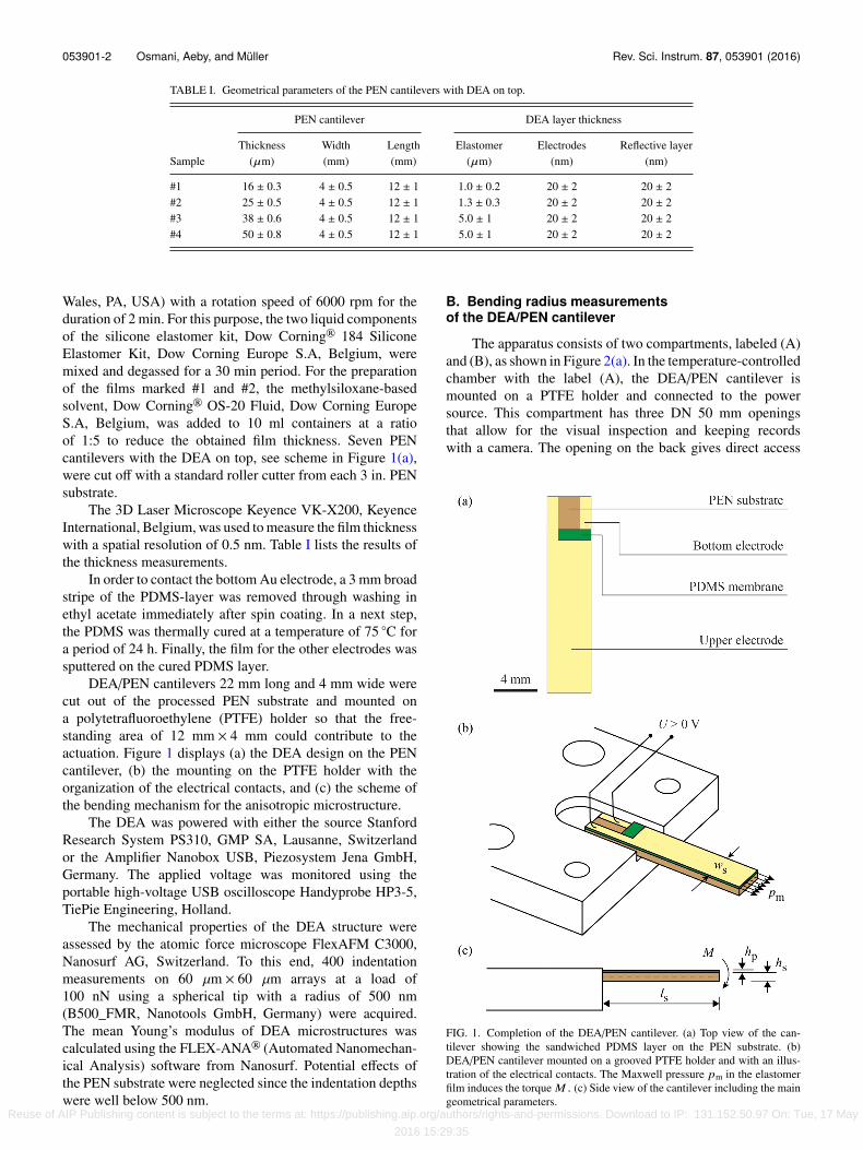
Wales, PA, USA) with a rotation speed of 6000 rpm for theduration of 2 min. For this purpose, the two liquid componentsof the silicone elastomer kit, Dow Corning® 184 SiliconeElastomer Kit, Dow Corning Europe S.A, Belgium, weremixed and degassed for a 30 min period. For the preparationof the films marked #1 and #2, the methylsiloxane-basedsolvent, Dow Corning® OS-20 Fluid, Dow Corning EuropeS.A, Belgium, was added to 10 ml containers at a ratioof 1:5 to reduce the obtained film thickness. Seven PENcantilevers with the DEA on top, see scheme in Figure 1(a),were cut off with a standard roller cutter from each 3 in. PENsubstrate.
The 3D Laser Microscope Keyence VK-X200, KeyenceInternational, Belgium, was used to measure the film thicknesswith a spatial resolution of 0.5 nm. Table I lists the results ofthe thickness measurements.
In order to contact the bottom Au electrode, a 3 mm broadstripe of the PDMS-layer was removed through washing inethyl acetate immediately after spin coating. In a next step,the PDMS was thermally cured at a temperature of 75 ◦C fora period of 24 h. Finally, the film for the other electrodes wassputtered on the cured PDMS layer.
DEA/PEN cantilevers 22 mm long and 4 mm wide werecut out of the processed PEN substrate and mounted ona polytetrafluoroethylene (PTFE) holder so that the free-standing area of 12 mm × 4 mm could contribute to theactuation. Figure 1 displays (a) the DEA design on the PENcantilever, (b) the mounting on the PTFE holder with theorganization of the electrical contacts, and (c) the scheme ofthe bending mechanism for the anisotropic microstructure.
The DEA was powered with either the source StanfordResearch System PS310, GMP SA, Lausanne, Switzerlandor the Amplifier Nanobox USB, Piezosystem Jena GmbH,Germany. The applied voltage was monitored using theportable high-voltage USB oscilloscope Handyprobe HP3-5,TiePie Engineering, Holland.
The mechanical properties of the DEA structure wereassessed by the atomic force microscope FlexAFM C3000,Nanosurf AG, Switzerland. To this end, 400 indentationmeasurements on 60 µm × 60 µm arrays at a load of100 nN using a spherical tip with a radius of 500 nm(B500_FMR, Nanotools GmbH, Germany) were acquired.The mean Young’s modulus of DEA microstructures wascalculated using the FLEX-ANA® (Automated Nanomechan-ical Analysis) software from Nanosurf. Potential effects ofthe PEN substrate were neglected since the indentation depthswere well below 500 nm.
B. Bending radius measurementsof the DEA/PEN cantilever
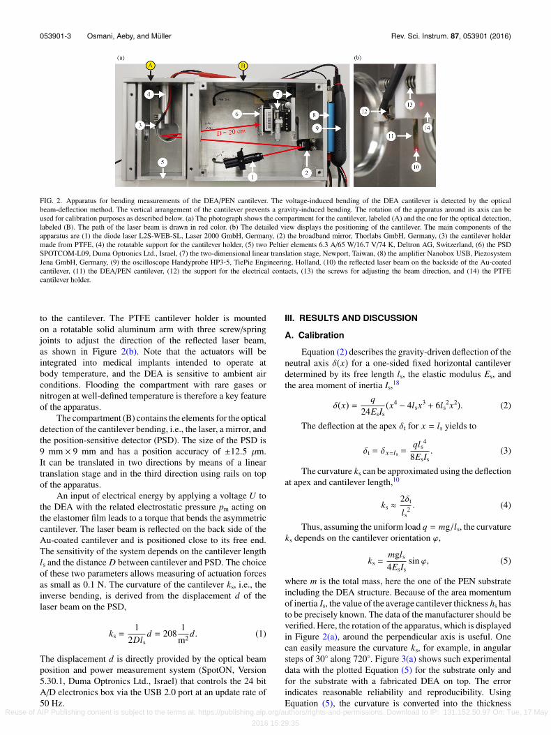
The apparatus consists of two compartments, labeled (A)and (B), as shown in Figure 2(a). In the temperature-controlledchamber with the label (A), the DEA/PEN cantilever ismounted on a PTFE holder and connected to the powersource. This compartment has three DN 50 mm openingsthat allow for the visual inspection and keeping recordswith a camera. The opening on the back gives direct access
FIG. 1. Completion of the DEA/PEN cantilever. (a) Top view of the can-tilever showing the sandwiched PDMS layer on the PEN substrate. (b)DEA/PEN cantilever mounted on a grooved PTFE holder and with an illus-tration of the electrical contacts. The Maxwell pressure pm in the elastomerfilm induces the torque M . (c) Side view of the cantilever including the maingeometrical parameters.
Reuse of AIP Publishing content is subject to the terms at: https://publishing.aip.org/authors/rights-and-permissions. Download to IP: 131.152.50.97 On: Tue, 17 May
2016 15:29:35
053901-3 Osmani, Aeby, and Müller Rev. Sci. Instrum. 87, 053901 (2016)
FIG. 2. Apparatus for bending measurements of the DEA/PEN cantilever. The voltage-induced bending of the DEA cantilever is detected by the opticalbeam-deflection method. The vertical arrangement of the cantilever prevents a gravity-induced bending. The rotation of the apparatus around its axis can beused for calibration purposes as described below. (a) The photograph shows the compartment for the cantilever, labeled (A) and the one for the optical detection,labeled (B). The path of the laser beam is drawn in red color. (b) The detailed view displays the positioning of the cantilever. The main components of theapparatus are (1) the diode laser L2S-WEB-SL, Laser 2000 GmbH, Germany, (2) the broadband mirror, Thorlabs GmbH, Germany, (3) the cantilever holdermade from PTFE, (4) the rotatable support for the cantilever holder, (5) two Peltier elements 6.3 A/65 W/16.7 V/74 K, Deltron AG, Switzerland, (6) the PSDSPOTCOM-L09, Duma Optronics Ltd., Israel, (7) the two-dimensional linear translation stage, Newport, Taiwan, (8) the amplifier Nanobox USB, PiezosystemJena GmbH, Germany, (9) the oscilloscope Handyprobe HP3-5, TiePie Engineering, Holland, (10) the reflected laser beam on the backside of the Au-coatedcantilever, (11) the DEA/PEN cantilever, (12) the support for the electrical contacts, (13) the screws for adjusting the beam direction, and (14) the PTFEcantilever holder.
to the cantilever. The PTFE cantilever holder is mountedon a rotatable solid aluminum arm with three screw/springjoints to adjust the direction of the reflected laser beam,as shown in Figure 2(b). Note that the actuators will beintegrated into medical implants intended to operate atbody temperature, and the DEA is sensitive to ambient airconditions. Flooding the compartment with rare gases ornitrogen at well-defined temperature is therefore a key featureof the apparatus.
The compartment (B) contains the elements for the opticaldetection of the cantilever bending, i.e., the laser, a mirror, andthe position-sensitive detector (PSD). The size of the PSD is9 mm × 9 mm and has a position accuracy of ±12.5 µm.It can be translated in two directions by means of a lineartranslation stage and in the third direction using rails on topof the apparatus.
An input of electrical energy by applying a voltage U tothe DEA with the related electrostatic pressure pm acting onthe elastomer film leads to a torque that bends the asymmetriccantilever. The laser beam is reflected on the back side of theAu-coated cantilever and is positioned close to its free end.The sensitivity of the system depends on the cantilever lengthls and the distance D between cantilever and PSD. The choiceof these two parameters allows measuring of actuation forcesas small as 0.1 N. The curvature of the cantilever ks, i.e., theinverse bending, is derived from the displacement d of thelaser beam on the PSD,
ks =1
2Dlsd = 208
1m2 d. (1)
The displacement d is directly provided by the optical beamposition and power measurement system (SpotON, Version5.30.1, Duma Optronics Ltd., Israel) that controls the 24 bitA/D electronics box via the USB 2.0 port at an update rate of50 Hz.
III. RESULTS AND DISCUSSION
A. Calibration
Equation (2) describes the gravity-driven deflection of theneutral axis δ(x) for a one-sided fixed horizontal cantileverdetermined by its free length ls, the elastic modulus Es, andthe area moment of inertia Is,18
δ(x) = q24EsIs
(x4 − 4lsx3 + 6ls2x2). (2)
The deflection at the apex δt for x = ls yields to
δt = δx=ls =qls
4
8EsIs. (3)
The curvature ks can be approximated using the deflectionat apex and cantilever length,10
ks ≈2δt
ls2 . (4)
Thus, assuming the uniform load q = mg/ls, the curvatureks depends on the cantilever orientation ϕ,
ks =mgls
4EsIssin ϕ, (5)
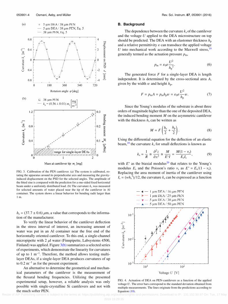
where m is the total mass, here the one of the PEN substrateincluding the DEA structure. Because of the area momentumof inertia Is, the value of the average cantilever thickness hs hasto be precisely known. The data of the manufacturer should beverified. Here, the rotation of the apparatus, which is displayedin Figure 2(a), around the perpendicular axis is useful. Onecan easily measure the curvature ks, for example, in angularsteps of 30◦ along 720◦. Figure 3(a) shows such experimentaldata with the plotted Equation (5) for the substrate only andfor the substrate with a fabricated DEA on top. The errorindicates reasonable reliability and reproducibility. UsingEquation (5), the curvature is converted into the thickness
Reuse of AIP Publishing content is subject to the terms at: https://publishing.aip.org/authors/rights-and-permissions. Download to IP: 131.152.50.97 On: Tue, 17 May
2016 15:29:35
053901-4 Osmani, Aeby, and Müller Rev. Sci. Instrum. 87, 053901 (2016)
FIG. 3. Calibration of the PEN cantilever. (a) The system is calibrated, ro-tating the apparatus around its perpendicular axis and measuring the gravity-induced displacement on the PSD for the selected angles. The amplitude ofthe fitted sine is compared with the prediction for a one-sided fixed horizontalbeam under a uniformly distributed load. (b) The curvature ks was measuredfor selected amounts of water placed near the tip of the cantilever in Alcontainer. The system shows a linear behavior for bending radii larger than1 m.
hs = (37.7 ± 0.6) µm, a value that corresponds to the informa-tion of the manufacturer.
To verify the linear behavior of the cantilever deflectionin the stress interval of interest, an increasing amount ofwater was put in an Al container near the free end of thehorizontally oriented cantilever. To this end, a single-channelmicropipette with 2 µl water (Finnpipette, Labsystems 4500,Finland) was applied. Figure 3(b) summarizes a selected seriesof experiments, which demonstrate the linearity for curvaturesof up to 1 m−1. Therefore, the method allows testing multi-layer DEAs, if a single-layer DEA produces curvatures of upto 0.2 m−1 as for the present experiment.
An alternative to determine the geometrical and mechan-ical parameters of the cantilever is the measurement ofthe flexural bending frequencies. Utilizing the presentedexperimental setup, however, a reliable analysis was onlypossible with single-crystalline Si cantilevers and not withthe much softer PEN.
B. Background
The dependence between the curvature ks of the cantileverand the voltage U applied to the DEA microstructure on topshould be predicted. The DEA with an elastomer thickness hpand a relative permittivity ε can transduce the applied voltageU into mechanical work according to the Maxwell stress,19
generally termed as the actuation pressure pm,
pm = ε0εU2
hp2 . (6)
The generated force F for a single-layer DEA is lengthindependent. It is determined by the cross-sectional area A,given by the width w and height hp,
F = pmA = pmhpw = ε0εU2
hpw. (7)
Since the Young’s modulus of the substrate is about threeorders of magnitude higher than the one of the deposited DEA,the induced bending moment M on the asymmetric cantileverwith the thickness hs can be written as
M = F(
hs
2+
hp
2
). (8)
Using the differential equation for the deflection of an elasticbeam,10 the curvature ks for small deflections is known as
ks =1R�
∂2z∂x2 �
ME∗I=
M(1 − νs)EsIs
, (9)
with E∗ as the biaxial modulus20 that relates to the Young’smodulus Es and the Poisson’s ratio νs as E∗ = Es/(1 − νs).Replacing the area moment of inertia of the cantilever usingIs = (whs
3)/12, the curvature ks can be expressed as a function
FIG. 4. Actuation of DEA on PEN-cantilevers as a function of the appliedvoltageU . The error bars correspond to the standard deviation obtained frommultiple measurements. The lines originate from the predictions according toEquation (10).
Reuse of AIP Publishing content is subject to the terms at: https://publishing.aip.org/authors/rights-and-permissions. Download to IP: 131.152.50.97 On: Tue, 17 May
2016 15:29:35
053901-5 Osmani, Aeby, and Müller Rev. Sci. Instrum. 87, 053901 (2016)
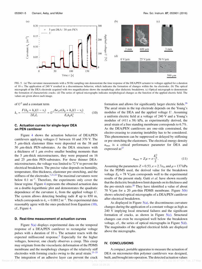
FIG. 5. (a) The curvature measurements with a 50 Hz sampling rate demonstrate the time response of the DEA/PEN actuator to voltages applied for a durationof 10 s. The application of 240 V resulted in a discontinuous behavior, which indicates the formation of changes within the Au electrodes. (b) The opticalmicrograph of the DEA electrode acquired with two magnifications shows the morphology after dielectric breakdown. (c) Optical micrograph to demonstratethe formation of characteristic cracks. (d) The series of optical micrographs indicates morphological changes as the function of the applied electric field. Thevalues are given above each image.
of U2 and a constant term
ks =F(hp + hs)(1 − νs)
2EsIs= U2 6εoε(hp + hs)(1 − νs)
Eshph3s
. (10)
C. Actuation curves for single-layer DEAon PEN cantilever
Figure 4 shows the actuation behavior of DEA/PENcantilevers applying voltages U between 10 and 370 V. The5 µm-thick elastomer films were deposited on the 38 and50 µm-thick PEN-substrates. As the DEA structures witha thickness of 1 µm evolve smaller bending moments thanthe 5 µm-thick microstructures, they were prepared on 16and 25 µm-thin PEN-substrates. For these thinner DEA-microstructures, the voltage was limited to 72 V to prevent theelectrical breakdown. The precise value depends on humidity,temperature, film thickness, elastomer pre-stretching, and thestiffness of the electrodes.7,21,22 The maximal curvatures werebelow 0.1 m−1. Therefore, the experiments only cover thelinear regime. Figure 4 represents the obtained actuation dataon a double-logarithmic plot and demonstrates the quadraticdependence of the curvature ks from the applied voltage U.The system allows detecting bending radii R up to 850 m,which corresponds to ks = 0.0012 m−1. The experimental datareasonably agree with the ones predicted from Equation (10),cf., Figure 4.
D. Real-time measurement of actuation curves
Figure 5(a) displays experimental data on the temporalresponse of a DEA/PEN cantilever to rectangular voltagepulses with a duration of 10 s. The actuator reacts with theexpected millisecond response.2 Especially for the highervoltages, however, one clearly observes a creep. This creepmay originate from the viscoelastic deformation of the PDMSmembrane and the morphology changes of the relatively stiffelectrodes with forming cracks owing to the areal strain.23–25
The integration of an adhesive layer can prevent the crack
formation and allows for significantly larger electric fields.26
The areal strain in the top electrode depends on the Young’smodulus of the DEA and the applied voltage U. Assuminga uniform electric field at a voltage of 240 V and a Young’smodulus of (411 ± 38) kPa, as experimentally derived, theareal strain of a free standing membrane corresponds to 6.7%.As the DEA/PEN cantilevers are one-side constrained, theelectro-creasing to cratering instability has to be considered.This phenomenon can be suppressed or delayed by stiffeningor pre-stretching the elastomers. The electrical energy densityumax is a critical performance parameter for DEA andexpressed as27
umax = Zµ = εE2
b
2. (11)
Assuming the parameters Z = 0.53, ε = 2.7ε0, and µ= 137 kPafor the PDMS used, the derived value for the breakdownvoltage Eb = 78 V/µm corresponds well to the experimentalresults of the present study. Gatti et al. have shown recentlythat the dielectric breakdown limit depends on its thickness andthe pre-stretch ratio.28 They have identified a value of about70 V/µm for a 20 µm-thin PDMS membrane. Figure 5(b)shows selected optical micrographs of a DEA/PEN cantileverafter electrical breakdown.
As displayed in Figure 5(a), the discontinuous curvaturechanges during the application of a constant voltage as high as240 V implying local structural failures and the significantformation of cracks, as shown in Figure 5(c). Structuralchanges can even be recognized well below the breakdownvoltage, cf., the series of optical micrographs in Figure 5(d).The magnitudes of the applied electrical fields are displayedabove the micrographs.
IV. CONCLUSIONS
A compact, portable apparatus to measure the actuation ofDEA on micrometer-thin polymer cantilevers was designed,built, and brought into operation. The detected actuation values
Reuse of AIP Publishing content is subject to the terms at: https://publishing.aip.org/authors/rights-and-permissions. Download to IP: 131.152.50.97 On: Tue, 17 May
2016 15:29:35
053901-6 Osmani, Aeby, and Müller Rev. Sci. Instrum. 87, 053901 (2016)
correspond reasonably well to the predictions. The actuationforce F of a single-layer DEA calculated from Equation (10)is below 1 mN. The apparatus is therefore well suited also forthe characterization of multi-layer actuators. The electricalbreakdown is observed at 80 V/µm that is smaller than thedielectric strength of 140 V/µm reported for the used siliconelastomer8 (Dow Corning® Sylgard 184). We presume thatimpurities and thickness variations within the elastomer layercaused the reduction. The presented apparatus for measuringthe voltage-dependent curvature will allow improving theactuator performance that includes the long-term behavior.
ACKNOWLEDGMENTS
The financial support of the nano-tera.ch initiative, projectSmartSphincter, is gratefully acknowledged. The authorsthank Sascha Martin from the machine shop at the PhysicsDepartment of the University Basel for the manufacturing ofthe mechanical components. Synflex GmbH, Germany kindlyprovided the PEN Teonex® Q51 substrates. The authors alsothank Monica Schönenberger from the Nanotech Service Labfor her assistance at the 3D Laser microscope as well as TinoTöpper, Vanessa Leung, and Florian Weiss for their support incomponent selection and discussion of technical details.
1J. D. W. Madden, N. A. Vandesteeg, P. A. Anquetil, P. G. A. Madden, A.Takshi, R. Z. Pytel, S. R. Lafontaine, P. A. Wieringa, and I. W. Hunter, IEEEJ. Oceanic Eng. 29(3), 706–728 (2004).
2R. Pelrine, Science 287(5454), 836–839 (2000).3Y. Bar-Cohen, Electroactive Polymer (EAP) Actuators as Artificial Muscles:Reality, Potential, and Challenges (SPIE Press, 2004).
4B. Müller, H. Deyhle, S. Mushkolaj, and M. Wieland, Swiss Med. Wkly139(41-42), 591–595 (2009).
5T. Töpper, F. M. Weiss, B. Osmani, C. Bippes, V. Leung, and B. Müller,Sens. Actuators, A 233, 32–41 (2015).
6A. O’Halloran, F. O’Malley, and P. McHugh, J. Appl. Phys. 104(7), 071101(2008).
7F. Carpi, I. Anderson, S. Bauer, G. Frediani, G. Gallone, M. Gei, C. Graaf, C.Jean-Mistral, W. Kaal, and G. Kofod, Smart Mater. Struct. 24(10), 105025(2015).
8P. Brochu and Q. Pei, Macromol. Rapid Commun. 31(1), 10–36(2010).
9D. Sander, A. Enders, and J. Kirschner, Rev. Sci. Instrum. 66(9), 4734–4735(1995).
10M. Godin, V. Tabard-Cossa, P. Grütter, and P. Williams, Appl. Phys. Lett.79(4), 551–553 (2001).
11C. A. Klein, J. Appl. Phys. 88(9), 5487–5489 (2000).12M. Liangruksa, Master thesis, Virginia Polytechnic Institute and State Uni-
versity, Virginia, 2008.13T. Itoh and T. Suga, Appl. Phys. Lett. 64(1), 37–39 (1994).14P. Urwyler, O. Häfeli, H. Schift, J. Gobrecht, F. Battiston, and B. Müller,
Procedia Eng. 5, 347–350 (2010).15J. Köser, S. Gaiser, and B. Müller, Eur. Cells Mater. 21, 479–487 (2011),
http://www.ncbi.nlm.nih.gov/pubmed/21623572.16A. Markidou, W. Y. Shih, and W. H. Shih, Rev. Sci. Instrum. 76(6), 064302
(2005).17M. Bicker, U. Von Hülsen, U. Laudahn, A. Pundt, and U. Geyer, Rev. Sci.
Instrum. 69, 460–462 (1998).18W. Flügge, Handbook of Engineering Mechanics (McGraw-Hill, New York,
1962).19R. Pelrine, R. Kornbluh, J. Joseph, R. Heydt, Q. Pei, and S. Chiba, Mater.
Sci. Eng. C 11(2), 89–100 (2000).20T. Miyatani and M. Fujihira, J. Appl. Phys. 81(11), 7099–7115
(1997).21B. Osmani, T. Töpper, C. Deschenaux, J. Nohava, F. M. Weiss, V. Leung,
and B. Müller, AIP Conf. Proc. 1646(1), 91–100 (2015).22S. Rosset and H. Shea, Appl. Phys. A 110(2), 281–307 (2013).23I. M. Graz, D. P. Cotton, and S. P. Lacour, Appl. Phys. Lett. 94(7), 071902
(2009).24T. Töpper, B. Osmani, F. M. Weiss, C. Winterhalter, F. Wohlfender, V.
Leung, and B. Müller, Proc. SPIE 9430, 94300B (2015).25K. Jia, T. Lu, and T. J. Wang, Sens. Actuators, A 239, 8–17 (2016).26B. Osmani, H. Deyhle, F. M. Weiss, T. Töpper, M. Karapetkova, V. Leung,
and B. Müller, Proc. SPIE 9798, 979822 (2016).27X. Zhao and Q. Wang, Appl. Phys. Rev. 1(2), 021304 (2014).28D. Gatti, H. Haus, M. Matysek, B. Frohnapfel, C. Tropea, and H. F. Schlaak,
Appl. Phys. Lett. 104(5), 052905 (2014).
Reuse of AIP Publishing content is subject to the terms at: https://publishing.aip.org/authors/rights-and-permissions. Download to IP: 131.152.50.97 On: Tue, 17 May
2016 15:29:35


![Silicone rubbers for dielectric elastomers with improved ......dielectric elastomer (DE) formulation due to their favorable electro-mechanical properties. [1] Dielectric elastomers](https://img.pdfslide.net/doc/110x75/60a7aa8430c09b569000940a/silicone-rubbers-for-dielectric-elastomers-with-improved-dielectric-elastomer.jpg)