Embed Size (px)
Citation preview
4.1
PMcL Contents Index
2019 4 - Mesh Analysis
4 Mesh Analysis
Contents
Introduction ..................................................................................................... 4.2
4.1 Mesh Analysis ........................................................................................... 4.3 4.1.1 Planar Circuits .............................................................................. 4.3 4.1.2 Paths, Loops and Meshes .............................................................. 4.4
4.1.3 Mesh Current ................................................................................ 4.5 4.1.4 Mesh Analysis Methodology ........................................................ 4.6 4.1.5 Circuits with Resistors and Independent Voltage Sources Only .. 4.7 4.1.6 Circuits with Current Sources ....................................................... 4.9
4.1.7 Summary of Mesh Analysis ....................................................... 4.11
4.2 Summary .................................................................................................. 4.12
4.3 References ............................................................................................... 4.12
Exercises ........................................................................................................ 4.13
4.2
Index Introduction PMcL
4 - Mesh Analysis 2019
Introduction
Mesh analysis is a method that can be applied to any planar circuit (i.e. to
circuits that are able to be laid out on a 2D surface without crossing elements).
Both of these methods are widely used in hand design and computer
simulation. A third technique, known as loop analysis, generalises mesh
analysis and can be applied to any circuit – it is effectively the “dual” of nodal
analysis.
We will find that the judicious selection of an analysis technique can lead to a
drastic reduction in the number of equations to solve, and we should therefore
try to develop an ability to select the most convenient analysis method for a
particular circuit.
4.3
PMcL Mesh Analysis Index
2019 4 - Mesh Analysis
4.1 Mesh Analysis
Before we embark on mesh analysis, we need to define the concept of: a planar
circuit; a path through a circuit; a loop and a mesh. We can then outline the
analysis strategy using these terms.
4.1.1 Planar Circuits
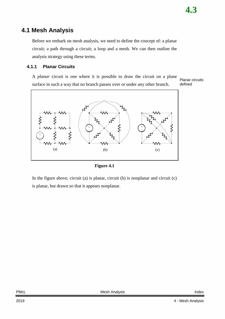
A planar circuit is one where it is possible to draw the circuit on a plane
surface in such a way that no branch passes over or under any other branch.
(a) (b) (c)
Figure 4.1
In the figure above, circuit (a) is planar, circuit (b) is nonplanar and circuit (c)
is planar, but drawn so that it appears nonplanar.
Planar circuits defined
4.4
Index Mesh Analysis PMcL
4 - Mesh Analysis 2019
4.1.2 Paths, Loops and Meshes
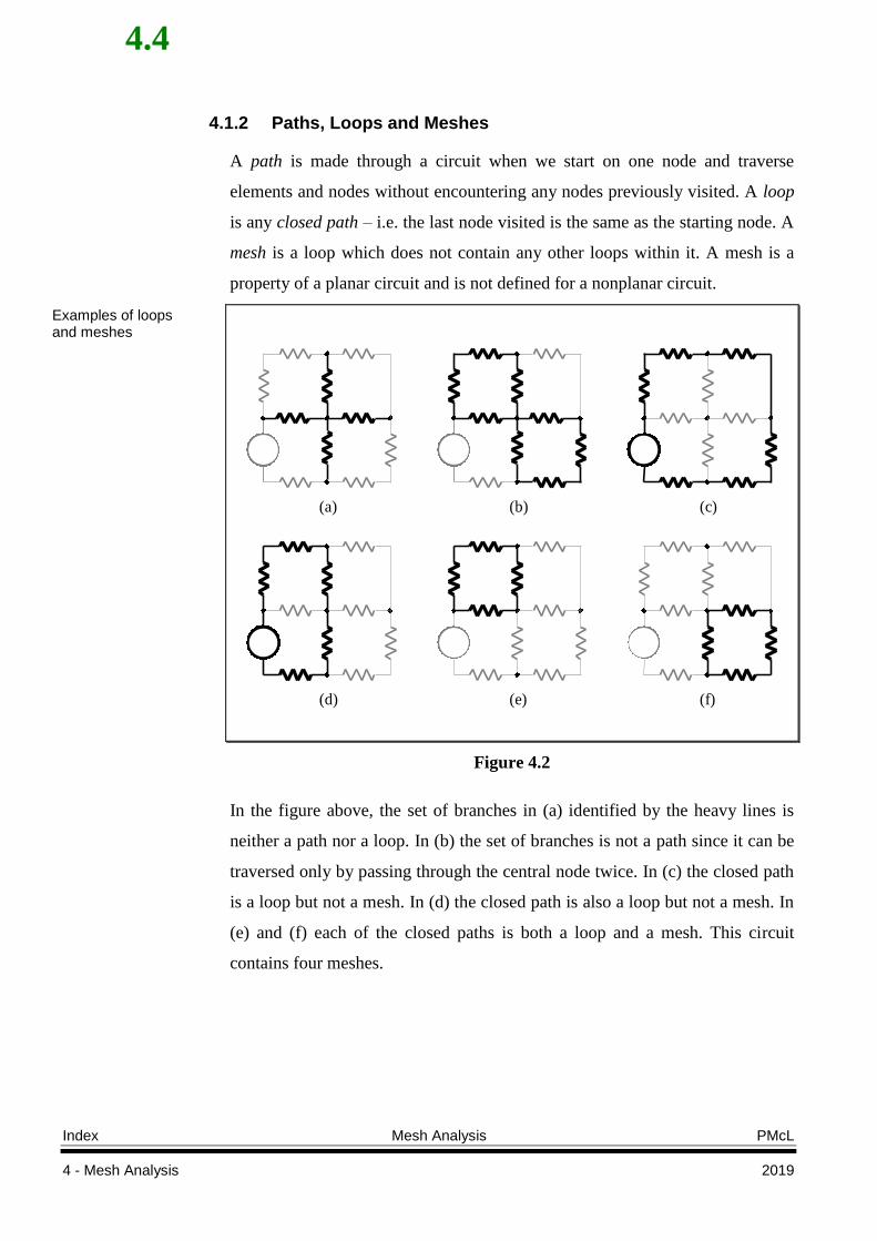
A path is made through a circuit when we start on one node and traverse
elements and nodes without encountering any nodes previously visited. A loop
is any closed path – i.e. the last node visited is the same as the starting node. A
mesh is a loop which does not contain any other loops within it. A mesh is a
property of a planar circuit and is not defined for a nonplanar circuit.
(a) (b) (c)
(d) (e) (f)
Figure 4.2
In the figure above, the set of branches in (a) identified by the heavy lines is
neither a path nor a loop. In (b) the set of branches is not a path since it can be
traversed only by passing through the central node twice. In (c) the closed path
is a loop but not a mesh. In (d) the closed path is also a loop but not a mesh. In
(e) and (f) each of the closed paths is both a loop and a mesh. This circuit
contains four meshes.
Examples of loops and meshes
4.5
PMcL Mesh Analysis Index
2019 4 - Mesh Analysis
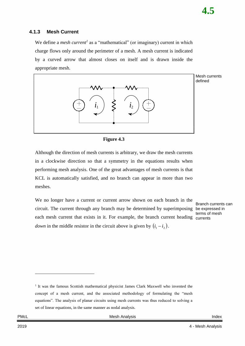
4.1.3 Mesh Current
We define a mesh current1 as a “mathematical” (or imaginary) current in which
charge flows only around the perimeter of a mesh. A mesh current is indicated
by a curved arrow that almost closes on itself and is drawn inside the
appropriate mesh.
i1 i2
Figure 4.3
Although the direction of mesh currents is arbitrary, we draw the mesh currents
in a clockwise direction so that a symmetry in the equations results when
performing mesh analysis. One of the great advantages of mesh currents is that
KCL is automatically satisfied, and no branch can appear in more than two
meshes.
We no longer have a current or current arrow shown on each branch in the
circuit. The current through any branch may be determined by superimposing
each mesh current that exists in it. For example, the branch current heading
down in the middle resistor in the circuit above is given by 21 ii .
1 It was the famous Scottish mathematical physicist James Clark Maxwell who invented the
concept of a mesh current, and the associated methodology of formulating the “mesh
equations”. The analysis of planar circuits using mesh currents was thus reduced to solving a
set of linear equations, in the same manner as nodal analysis.
Mesh currents defined
Branch currents can be expressed in terms of mesh currents
4.6
Index Mesh Analysis PMcL
4 - Mesh Analysis 2019
4.1.4 Mesh Analysis Methodology
In general terms, mesh analysis for a planar circuit with M meshes proceeds as
follows:
1. Assign a clockwise mesh current in each of the M meshes.
2. Write KVL around each mesh, in terms of the mesh currents.
3. Solve the resulting set of simultaneous equations.
As will be seen, the method outlined above becomes a little complicated if the
circuit contains current sources and / or controlled sources, but the principle
remains the same.
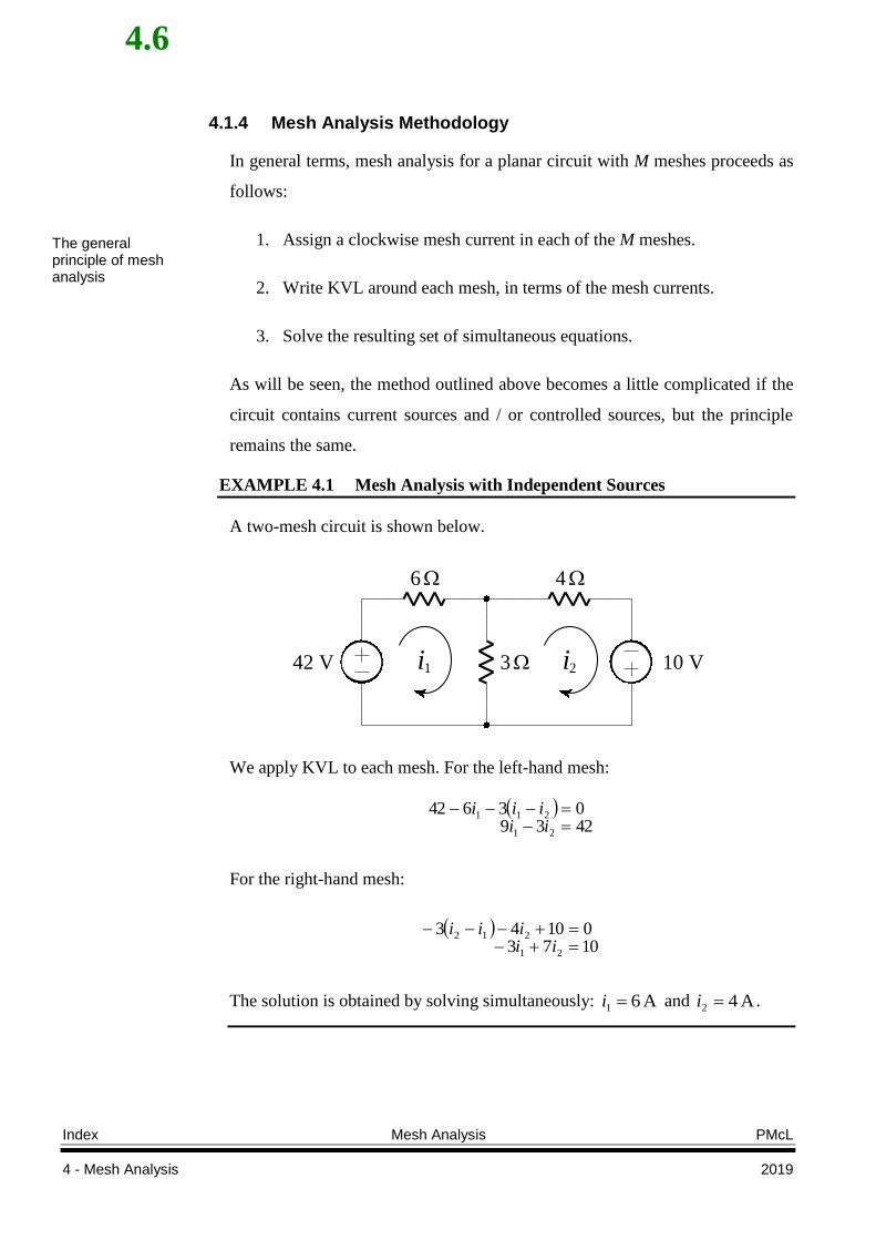
EXAMPLE 4.1 Mesh Analysis with Independent Sources
A two-mesh circuit is shown below.
i1 i242 V 3 10 V
6 4
We apply KVL to each mesh. For the left-hand mesh:
423903642
21
211
iiiii
For the right-hand mesh:
107301043
21
212
iiiii
The solution is obtained by solving simultaneously: A 61 i and A 42 i .
The general principle of mesh analysis
4.7
PMcL Mesh Analysis Index
2019 4 - Mesh Analysis
4.1.5 Circuits with Resistors and Independent Voltage Sources Only
When the circuit contains only resistors and voltages sources, the KVL
equations have a certain symmetrical form and we can define a resistance
matrix with the circuit. We will find again that the matrix equation can be
formulated by inspection of the circuit.
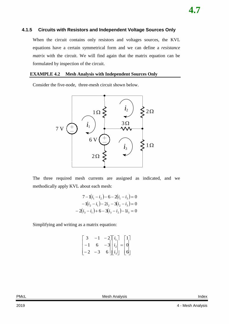
EXAMPLE 4.2 Mesh Analysis with Independent Sources Only
Consider the five-node, three-mesh circuit shown below.
i1
i2
7 V
1
6 V
3
2
1
2
i3
The three required mesh currents are assigned as indicated, and we
methodically apply KVL about each mesh:
01362
0321
02617
32313
32212
3121
iiiii
iiiii
iiii
Simplifying and writing as a matrix equation:
6
0
1
632
361
213
3
2
1
i
i
i
4.8
Index Mesh Analysis PMcL
4 - Mesh Analysis 2019
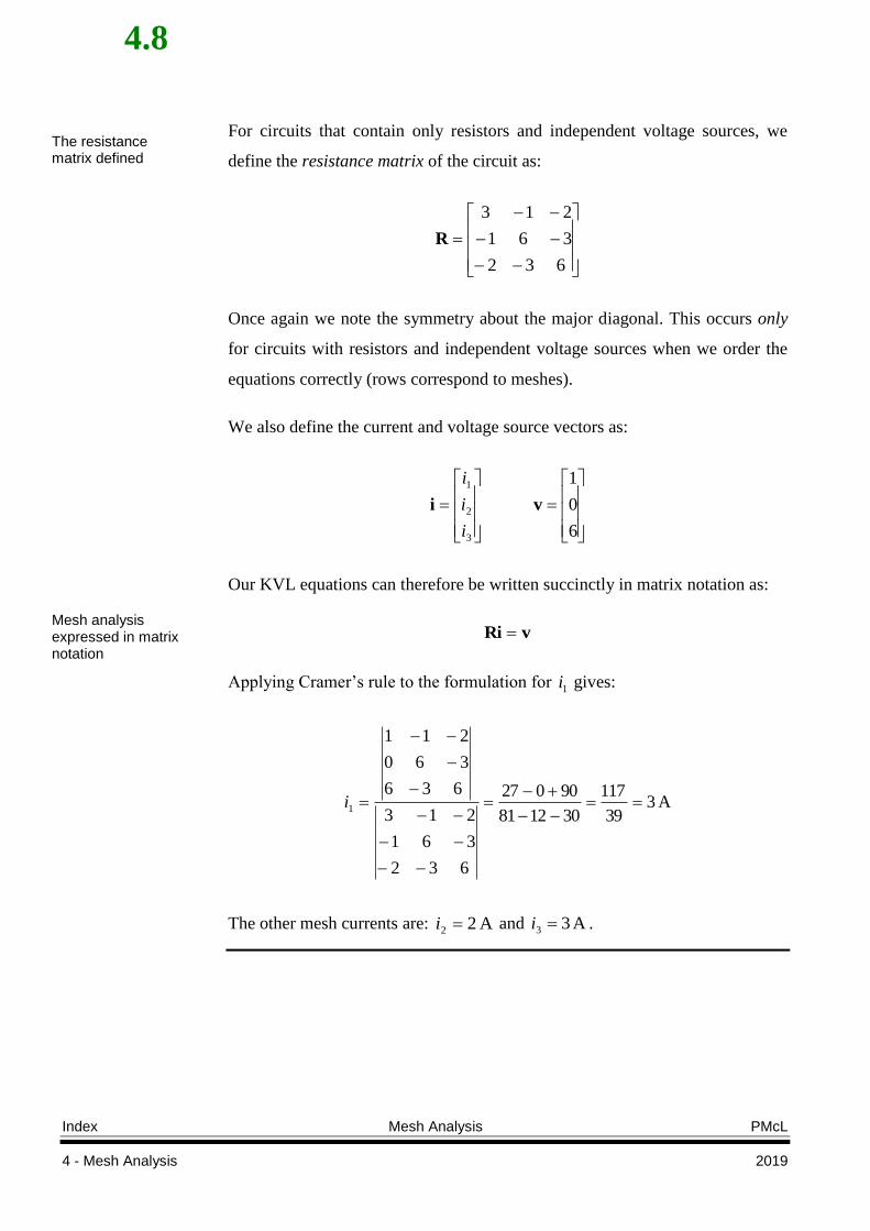
For circuits that contain only resistors and independent voltage sources, we
define the resistance matrix of the circuit as:
632
361
213
R
Once again we note the symmetry about the major diagonal. This occurs only
for circuits with resistors and independent voltage sources when we order the
equations correctly (rows correspond to meshes).
We also define the current and voltage source vectors as:
6
0
1
3
2
1
vi
i
i
i
Our KVL equations can therefore be written succinctly in matrix notation as:
vRi
Applying Cramer’s rule to the formulation for 1i gives:
A 339
117
301281
90027
632
361
213
636
360
211
1
i
The other mesh currents are: A 22 i and A 33 i .
The resistance matrix defined
Mesh analysis expressed in matrix notation
4.9
PMcL Mesh Analysis Index
2019 4 - Mesh Analysis
4.1.6 Circuits with Current Sources
When a mesh has a current source in it, we must modify the procedure for
forming the circuit equations. There are two possible methods. In the first
method, we can relate the source current to the assigned mesh currents, assign
an arbitrary voltage across it (thereby increasing the number of variables by
one) and write KVL equations using this voltage. Alternately, a better method
is to take a lead from nodal analysis and formulate the dual of a supernode - a
supermesh.
To create a supermesh, we open-circuit or remove current sources, thereby
reducing the total number of meshes. We apply KVL only to those meshes in
the modified circuit.
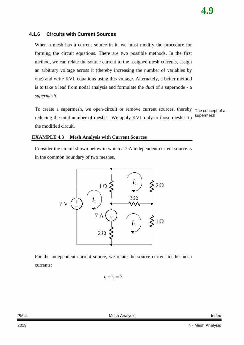
EXAMPLE 4.3 Mesh Analysis with Current Sources
Consider the circuit shown below in which a 7 A independent current source is
in the common boundary of two meshes.
i1
i2
7 V
1
7 A
3
2
1
2
i3
For the independent current source, we relate the source current to the mesh
currents:
731 ii
The concept of a supermesh
4.10
Index Mesh Analysis PMcL
4 - Mesh Analysis 2019
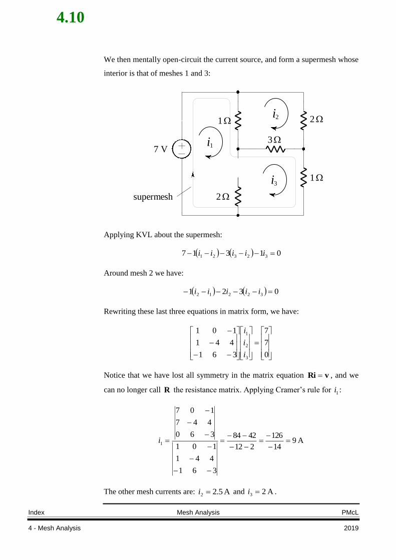
We then mentally open-circuit the current source, and form a supermesh whose
interior is that of meshes 1 and 3:
i1
i2
7 V
1
3
2
1
2
i3
supermesh
Applying KVL about the supermesh:
01317 32321 iiiii
Around mesh 2 we have:
0321 32212 iiiii
Rewriting these last three equations in matrix form, we have:
0
7
7
361
441
101
3
2
1
i
i
i
Notice that we have lost all symmetry in the matrix equation vRi , and we
can no longer call R the resistance matrix. Applying Cramer’s rule for 1i :
A 914
126
212
4284
361
441
101
360
447
107
1
i
The other mesh currents are: A 5.22 i and A 23 i .
4.11
PMcL Mesh Analysis Index
2019 4 - Mesh Analysis
4.1.7 Summary of Mesh Analysis
We perform mesh analysis for any resistive circuit with M meshes by the
following method:
1. Make certain that the circuit is a planar circuit. If it is nonplanar, then
mesh analysis is not applicable.
2. Make a neat, simple, circuit diagram. Indicate all element and source
values. Each source should have its reference symbol.
3. Assuming that the circuit has M meshes, assign a clockwise mesh
current in each mesh, 1i ,
2i , …, Mi .
4. If the circuit contains current sources, temporarily modify the given
circuit by replacing each current source by an open-circuit to form
supermeshes, thus reducing the number of meshes by one for each
current source that is present. The assigned mesh currents should not be
changed. Relate each source current to the mesh currents.
5. Apply KVL around each of the meshes or supermeshes. If the circuit
has only resistors and independent voltage sources, then the equations
may be formed by inspection.
6. Solve the resulting set of simultaneous equations.
The general procedure to follow when undertaking mesh analysis
4.12
Index Summary PMcL
4 - Mesh Analysis 2019
4.2 Summary
Mesh analysis can only be applied to planar circuits. Apart from relating
source currents to mesh currents, the equations of mesh analysis are formed
from application of Kirchhoff’s Voltage Law.
In mesh analysis, a supermesh is formed by open-circuiting a current
source and treating the perimeter of the original two meshes as a single
mesh.
4.3 References
Hayt, W. & Kemmerly, J.: Engineering Circuit Analysis, 3rd Ed., McGraw-
Hill, 1984.
4.13
PMcL Exercises Index
2019 4 - Mesh Analysis
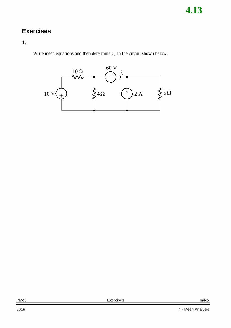
Exercises
1.
Write mesh equations and then determine xi in the circuit shown below:
10 V 4 2 A
10
5
60 Vix
4.14
Index Index PMcL
4 - Mesh Analysis 2019
Index
circuits
planar, 3.3
current
mesh, 3.5
loop, 3.4
mesh, 3.4
mesh analysis, 3.3
circuits with current sources, 3.9
circuits with resistors and
independent voltage sources only,
3.7
methodology, 3.6
path, 3.4
closed, 3.4