Embed Size (px)
Citation preview
BYSTBYSTCircuit -F2003: Nodal and Mesh AnalysisCircuit -F2003: Nodal and Mesh Analysis 1
CPE220 Electric Circuit CPE220 Electric Circuit AnalysisAnalysis
Chapter 3:Nodal and Mesh Analyses
BYSTBYSTCircuit -F2003: Nodal and Mesh AnalysisCircuit -F2003: Nodal and Mesh Analysis 2
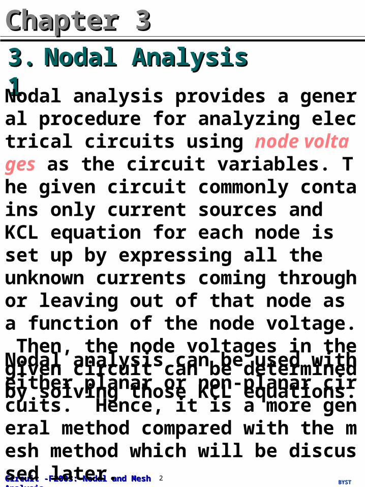
Nodal AnalysisNodal Analysis3.13.1
Chapter 3Chapter 3
Nodal analysis provides a general procedure for analyzing electrical circuits using node voltages as the circuit variables. The given circuit commonly contains only current sources and KCL equation for each node is set up by expressing all the unknown currents coming through or leaving out of that node as a function of the node voltage. Then, the node voltages in the given circuit can be determined by solving those KCL equations.
Nodal analysis can be used with either planar or non-planar circuits. Hence, it is a more general method compared with the mesh method which will be discussed later.
BYSTBYSTCircuit -F2003: Nodal and Mesh AnalysisCircuit -F2003: Nodal and Mesh Analysis 3
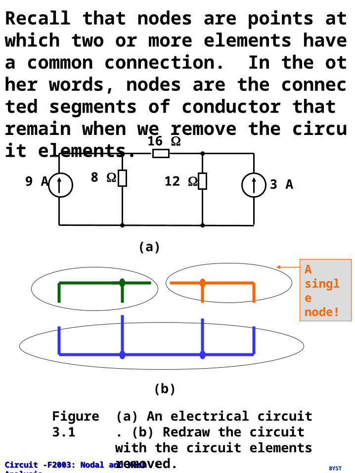
Recall that nodes are points at which two or more elements have a common connection. In the other words, nodes are the connected segments of conductor that remain when we remove the circuit elements.
9 A
16
8 12 3 A
(a)
A single node!
(b)
Figure 3.1 (a) An electrical circuit. (b) Redraw the circuit with the circuit elements removed.
BYSTBYSTCircuit -F2003: Nodal and Mesh AnalysisCircuit -F2003: Nodal and Mesh Analysis 4
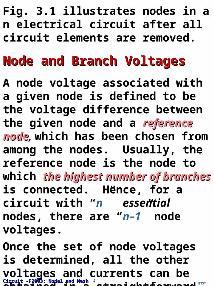
Fig. 3.1 illustrates nodes in an electrical circuit after all circuit elements are removed.
Node and Branch VoltagesNode and Branch Voltages
A node voltage associated with a given node is defined to be the voltage difference between the given node and a referencereference nodenode, which has been chosen from among the nodes. Usually, the reference node is the node to which the highest number of the highest number of branchesbranches is connected. Hence, for a circuit with “n” essential nodes, there are “n–1” node voltages.
Once the set of node voltages is determined, all the other voltages and currents can be obtained in a straightforward manner.
BYSTBYSTCircuit -F2003: Nodal and Mesh AnalysisCircuit -F2003: Nodal and Mesh Analysis 5
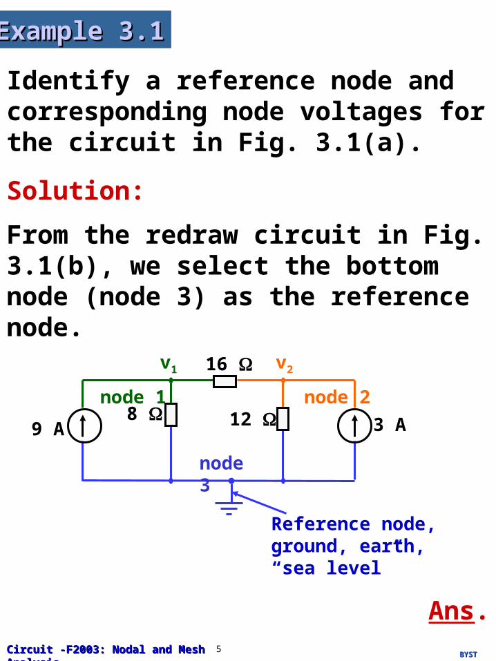
Identify a reference node and corresponding node voltages for the circuit in Fig. 3.1(a).
Example 3.1Example 3.1
Solution:
From the redraw circuit in Fig. 3.1(b), we select the bottom node (node 3) as the reference node.
node 1
v1 v2
Reference node, ground, earth, “sea level”
9 A
16
8 12 3 A
node 2
node 3
Ans.
BYSTBYSTCircuit -F2003: Nodal and Mesh AnalysisCircuit -F2003: Nodal and Mesh Analysis 6
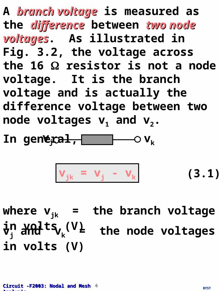
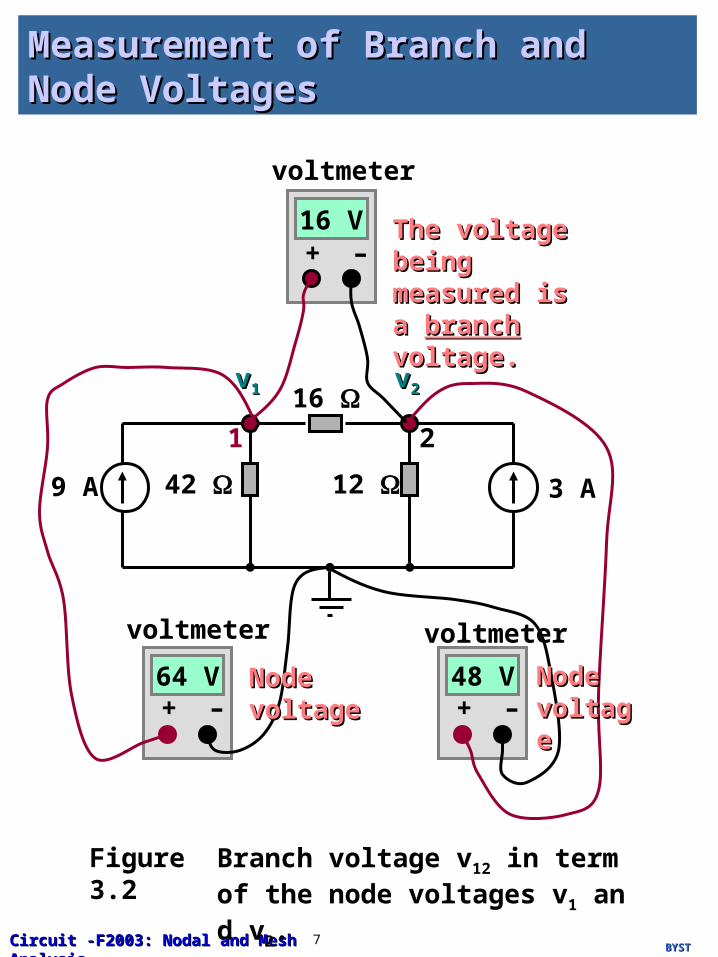
A branch voltagebranch voltage is measured as the differencedifference between two node voltagestwo node voltages. As illustrated in Fig. 3.2, the voltage across the 16 resistor is not a node voltage. It is the branch voltage and is actually the difference voltage between two node voltages v1 and v2.
In general,
vj vk
vjk = vj - vk (3.1)
where vjk = the branch voltage in volts (V)
vj and vk = the node voltages in volts (V)
BYSTBYSTCircuit -F2003: Nodal and Mesh AnalysisCircuit -F2003: Nodal and Mesh Analysis 7
Measurement of Branch and Node Measurement of Branch and Node VoltagesVoltages
9 A
16
42 12 3 A
1 2
vv11 vv22
64 V 48 V
16 V
voltmeter voltmeter
voltmeter
+ – + –
+ –The voltage The voltage being measured being measured is a is a branchbranch voltage.voltage.
Node Node voltagevoltage
Node Node voltagevoltage
Figure 3.2 Branch voltage v12 in term of the node voltages v1 and v2.
BYSTBYSTCircuit -F2003: Nodal and Mesh AnalysisCircuit -F2003: Nodal and Mesh Analysis 8
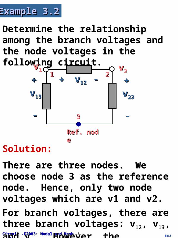
Determine the relationship among the branch voltages and the node voltages in the following circuit.
Example 3.2Example 3.2
Solution:
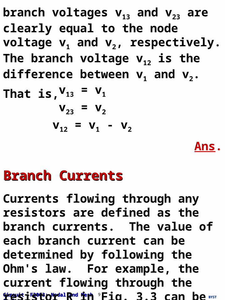
There are three nodes. We choose node 3 as the reference node. Hence, only two node voltages which are v1 and v2.
For branch voltages, there are three branch voltages: v12, v13, and v23. However, the
vv11 vv22
Ref. nodeRef. node
11 22
33
vv1212++ --
vv1313
++
--
vv2323
++
--
BYSTBYSTCircuit -F2003: Nodal and Mesh AnalysisCircuit -F2003: Nodal and Mesh Analysis 9
branch voltages v13 and v23 are clearly equal to the node voltage v1 and v2, respectively. The branch voltage v12 is the difference between v1 and v2.
That is,v13 = v1
v23 = v2
v12 = v1 - v2
Ans.
Branch CurrentsBranch Currents
Currents flowing through any resistors are defined as the branch currents. The value of each branch current can be determined by following the Ohm's law. For example, the current flowing through the resistor R in Fig. 3.3 can be determine as following:

BYSTBYSTCircuit -F2003: Nodal and Mesh AnalysisCircuit -F2003: Nodal and Mesh Analysis 10
Rvvjj vvkk
Node jNode j Node kNode k
Figure 3.3 Branch currents flowing through the resistor R.
The branch current flowing from node j to node k which can be calculated as:
The branch current flowing from node k to node j which can be calculated as:
(3.2)ijk =vj -vk
R
(3.3)ikj =vk -vj
R
BYSTBYSTCircuit -F2003: Nodal and Mesh AnalysisCircuit -F2003: Nodal and Mesh Analysis 11
The rationale for nodal analysis is that once the node voltages are determined, all the other voltages and currents can be obtained in a simple manner.
The reference node is chosen by the circuit analyst. In electronic circuits, we frequently choose the node to which lots of branches are connected. In power systems, we usually choose “groundground” or “earthearth.”
Basic Procedure for Nodal Analysis:
1. Select the node to which the highest number of branches is connected as the reference node.
2. Set up KCL equations for other nodes by expressing the unknown currents as a
3.1.1 Nodal Analysis by Examples
BYSTBYSTCircuit -F2003: Nodal and Mesh AnalysisCircuit -F2003: Nodal and Mesh Analysis 12
function of the node voltages measured with respect to (w.r.t.) the reference node.
3. If the given circuit contains voltage sovoltage sourcesurces, KCL equations of those two nodes connected by a voltage source are combined to eliminate the redundancy of KCL equations since the additional information is available through the node voltage. For example, if nodes j and k are connected by a voltage source, then vj - vk is already known.
4. Solve KCL equations to determine the node voltages.

BYSTBYSTCircuit -F2003: Nodal and Mesh AnalysisCircuit -F2003: Nodal and Mesh Analysis 13
Determine the node voltages v1, v2, and v3 in the following circuit.
Example 3.3Example 3.3
-3A
3
15
-8A
-25A
vv11vv22
vv33
Reference nodeReference node
Solution:
KCL @ node 1
-8 -3 =v1 -v2
3 +v1 -v3
4(3.4)
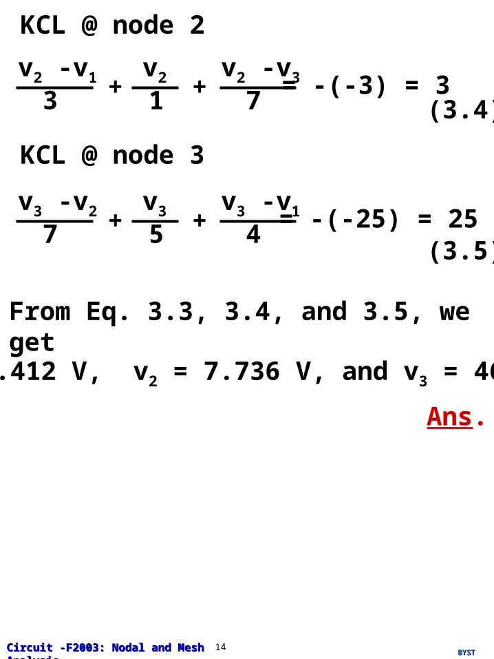
BYSTBYSTCircuit -F2003: Nodal and Mesh AnalysisCircuit -F2003: Nodal and Mesh Analysis 14
KCL @ node 2
= -(-3) = 3v2 -v1
3 +v2
1 (3.4)
v2 -v3
7+
KCL @ node 3
= -(-25) = 25v3 -v2
7 +v3
5(3.5)
v3 -v1
4+
From Eq. 3.3, 3.4, and 3.5, we get
v1 = 5.412 V, v2 = 7.736 V, and v3 = 46.32 V
Ans.
BYSTBYSTCircuit -F2003: Nodal and Mesh AnalysisCircuit -F2003: Nodal and Mesh Analysis 15
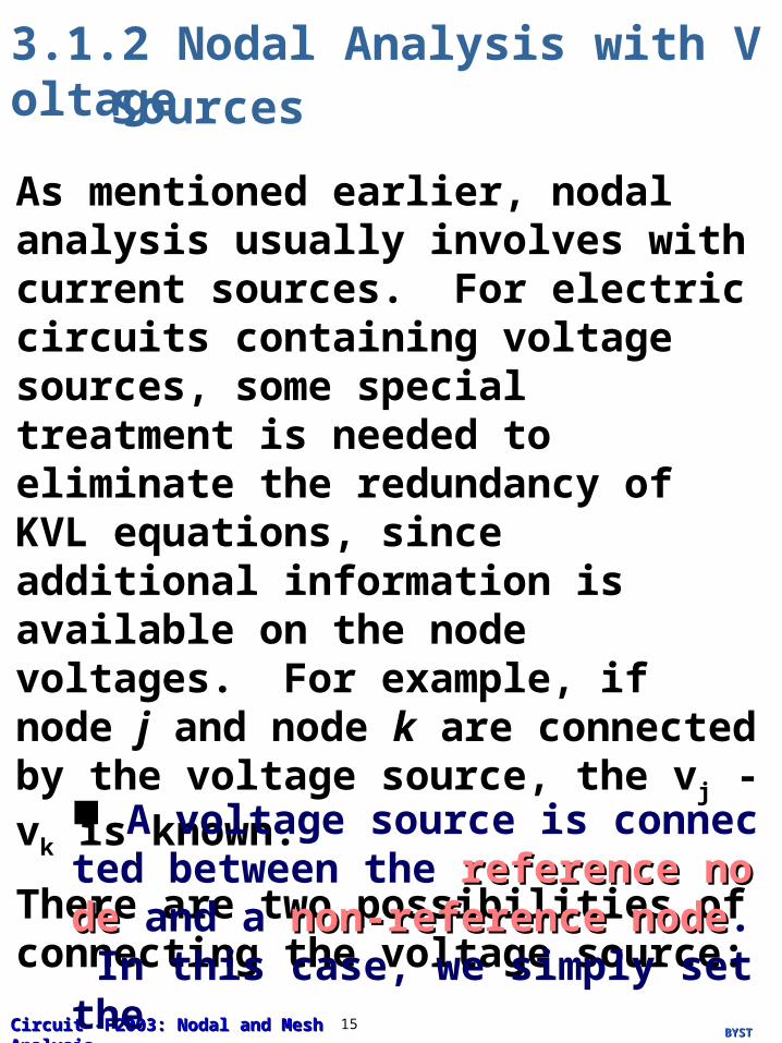
3.1.2 Nodal Analysis with VoltageSources
As mentioned earlier, nodal analysis usually involves with current sources. For electric circuits containing voltage sources, some special treatment is needed to eliminate the redundancy of KVL equations, since additional information is available on the node voltages. For example, if node j and node k are connected by the voltage source, the vj - vk is known.
There are two possibilities of connecting the voltage source:
A voltage source is connected between the reference nodereference node and a non-reference non-reference nodenode. In this case, we simply set the

BYSTBYSTCircuit -F2003: Nodal and Mesh AnalysisCircuit -F2003: Nodal and Mesh Analysis 16
SupernodesSupernodes
A supernodesupernode is a set of nodes connected to each other by voltage sourcevoltage source, but not to the reference node by a path of voltage source.
A voltage source is connected between the two non-reference nodesnon-reference nodes. In this case, the two non-reference nodes form a "ssupernodeupernode". Both KCL and KVL are applied to determine the node voltages.
voltage at the non-reference node equal to the voltage of the voltage source.
5 V
Reference Reference nodenode
vvjj
(a)
vj = 5 V
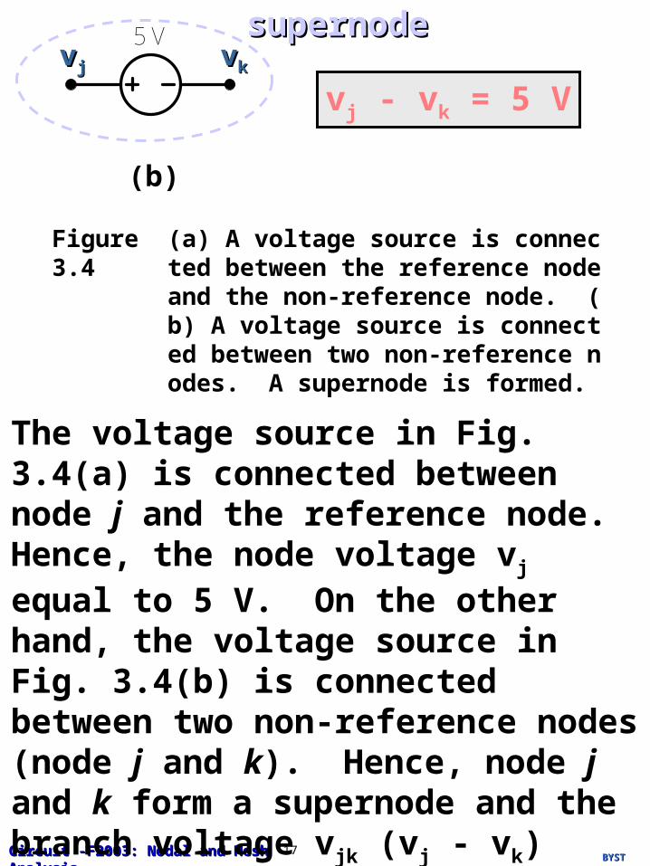
BYSTBYSTCircuit -F2003: Nodal and Mesh AnalysisCircuit -F2003: Nodal and Mesh Analysis 17
5 Vvvjj vvkk
(b)
vj - vk = 5 V
supernodesupernode
Figure 3.4 (a) A voltage source is connected between the reference node and the non-reference node. (b) A voltage source is connected between two non-reference nodes. A supernode is formed.
The voltage source in Fig. 3.4(a) is connected between node j and the reference node. Hence, the node voltage vj equal to 5 V. On the other hand, the voltage source in Fig. 3.4(b) is connected between two non-reference nodes (node j and k). Hence, node j and k form a supernode and the branch voltage vjk (vj - vk) equal to 5 V.
BYSTBYSTCircuit -F2003: Nodal and Mesh AnalysisCircuit -F2003: Nodal and Mesh Analysis 18
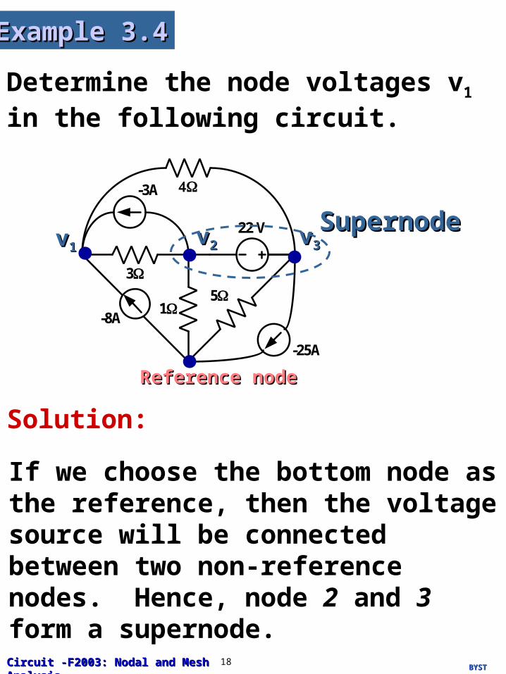
Determine the node voltages v1 in the following circuit.
Example 3.4Example 3.4
-3A
3
15
-8A
-25A
22 Vvv11 vv33
Reference nodeReference node
vv22
SupernodeSupernode
Solution:
If we choose the bottom node as the reference, then the voltage source will be connected between two non-reference nodes. Hence, node 2 and 3 form a supernode.
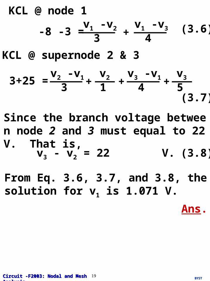
BYSTBYSTCircuit -F2003: Nodal and Mesh AnalysisCircuit -F2003: Nodal and Mesh Analysis 19
KCL @ node 1
-8 -3 =v1 -v2
3 +v1 -v3
4(3.6)
KCL @ supernode 2 & 3
3+25 =v2 -v1
3 +v2
1(3.7)
v3 -v1
4+v3
5+
Since the branch voltage between node 2 and 3 must equal to 22 V. That is,
v3 - v2 = 22 V. (3.8)
From Eq. 3.6, 3.7, and 3.8, the solution for v
1 is 1.071 V.
Ans.
BYSTBYSTCircuit -F2003: Nodal and Mesh AnalysisCircuit -F2003: Nodal and Mesh Analysis 20
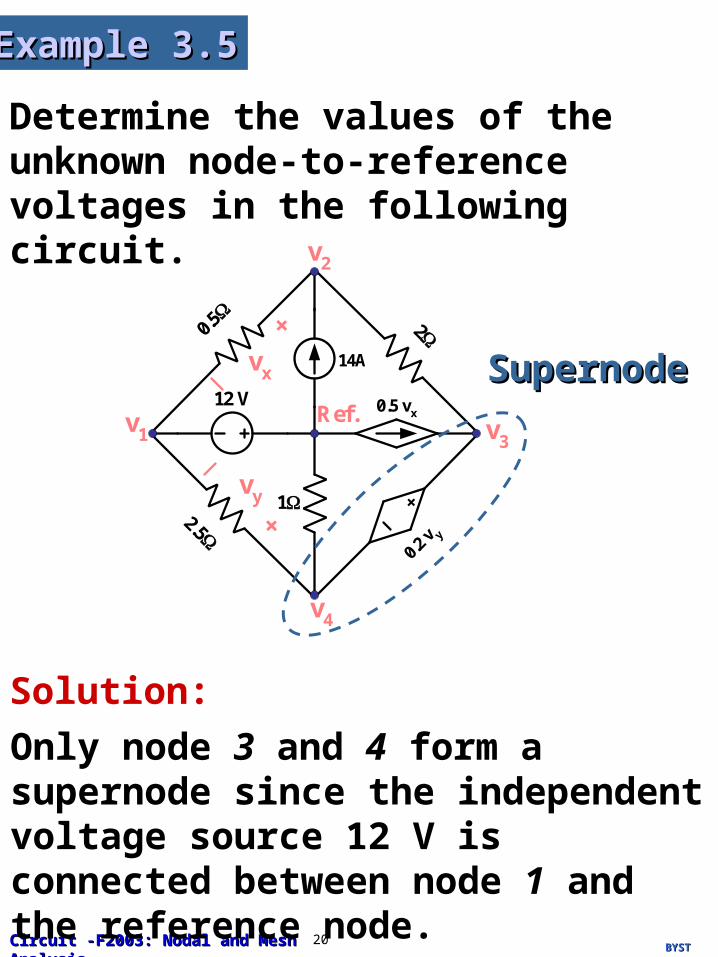
Determine the values of the unknown node-to-reference voltages in the following circuit.
Example 3.5Example 3.5
12 V
0.5
214A
2.5
+
0.5 vx
0.2 v y
1+
vy
+vx
Ref.v1
v2
v3
v4
Solution:
Only node 3 and 4 form a supernode since the independent voltage source 12 V is connected between node 1 and the reference node.
SupernodeSupernode
BYSTBYSTCircuit -F2003: Nodal and Mesh AnalysisCircuit -F2003: Nodal and Mesh Analysis 21
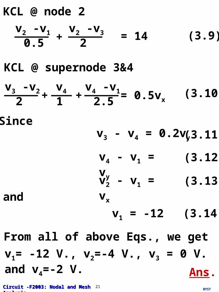
KCL @ node 2
v1 = -12
= 14v2 -v1
0.5 +v2 -v3
2(3.9)
KCL @ supernode 3&4
= 0.5vx
v3 -v2
2 +v4
1v4 -v1
2.5+ (3.10)
v3 - v4 = 0.2vy
Since
v4 - v1 = vy
(3.11)
(3.12)
v2 - v1 = vx (3.13)
and
(3.14)
From all of above Eqs., we get
v1= -12 V., v2=-4 V., v3 = 0 V. and v4=-2 V.
Ans.
BYSTBYSTCircuit -F2003: Nodal and Mesh AnalysisCircuit -F2003: Nodal and Mesh Analysis 22
Mesh AnalysisMesh Analysis3.23.2
For planar networks the mesh analysis provides another general procedure for analyzing electric circuits using mesh currentsmesh currents as the circuit variables. Basically, mesh analysis initially assumes that the currents flowing arcurrents flowing around the meshes are independentound the meshes are independent. A meshmesh is a circuit looploop that does not enclose any othdoes not enclose any other loop within iter loop within it. In the other words, a mesh is the smallest circuit loop.
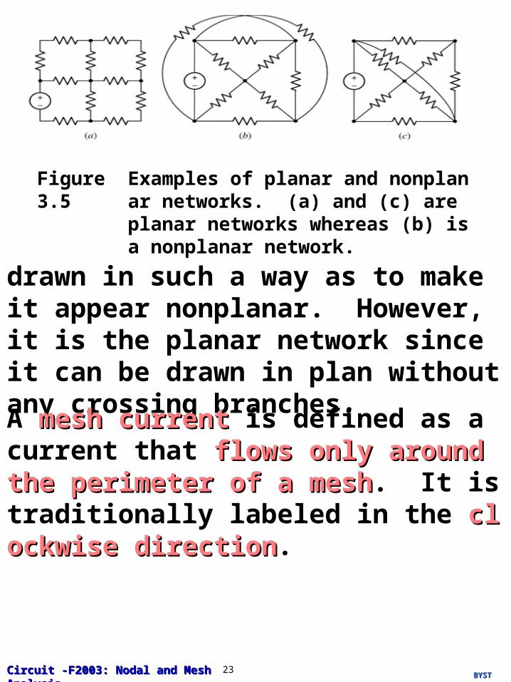
A planar network is a network that can be drawn in a plane with no branches crossing one another. Fig. 3.5 illustrates examples of planar and nonplanar networks. Network in Fig. 3.5(a) and (b) are clearly a planar network and a nonplanar network, respectively. The network in Fig. 3.5(c) is
BYSTBYSTCircuit -F2003: Nodal and Mesh AnalysisCircuit -F2003: Nodal and Mesh Analysis 23
Figure 3.5 Examples of planar and nonplanar networks. (a) and (c) are planar networks whereas (b) is a nonplanar network.
drawn in such a way as to make it appear nonplanar. However, it is the planar network since it can be drawn in plan without any crossing branches.
A mesh currentmesh current is defined as a current that flows only around the perimeter of a meshflows only around the perimeter of a mesh. It is traditionally labeled in the clockwise di clockwise directionrection.
BYSTBYSTCircuit -F2003: Nodal and Mesh AnalysisCircuit -F2003: Nodal and Mesh Analysis 24
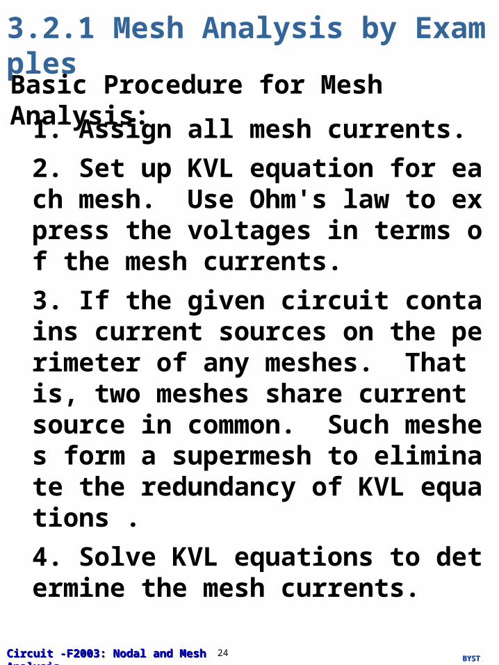
Basic Procedure for Mesh Analysis:
1. Assign all mesh currents.
2. Set up KVL equation for each mesh. Use Ohm's law to express the voltages in terms of the mesh currents.
3. If the given circuit contains current sources on the perimeter of any meshes. That is, two meshes share current source in common. Such meshes form a supermesh to eliminate the redundancy of KVL equations .
4. Solve KVL equations to determine the mesh currents.
3.2.1 Mesh Analysis by Examples
BYSTBYSTCircuit -F2003: Nodal and Mesh AnalysisCircuit -F2003: Nodal and Mesh Analysis 25
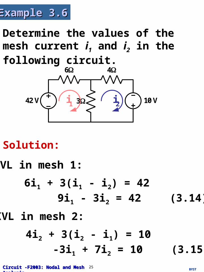
Determine the values of the mesh current i1 and i2 in the following circuit.
Example 3.6Example 3.6
6
42 V 3
4
10 Vi1 i2
Solution:
KVL in mesh 1:
6i1 + 3(i1 - i2) = 42
(3.14)9i1 - 3i2 = 42
KVL in mesh 2:
4i2 + 3(i2 - i1) = 10
(3.15)-3i1 + 7i2 = 10
BYSTBYSTCircuit -F2003: Nodal and Mesh AnalysisCircuit -F2003: Nodal and Mesh Analysis 26
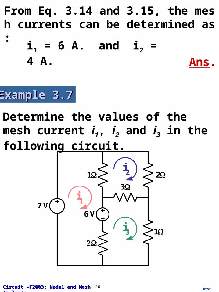
From Eq. 3.14 and 3.15, the mesh currents can be determined as:
i1 = 6 A. and i2 = 4 A.
Ans.
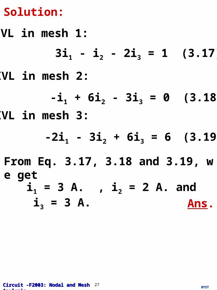
Determine the values of the mesh current i1, i2 and i3 in the following circuit.
Example 3.7Example 3.7
7 V
13
i1
i2
6 V
2
1i3
BYSTBYSTCircuit -F2003: Nodal and Mesh AnalysisCircuit -F2003: Nodal and Mesh Analysis 27
Solution:
KVL in mesh 1:
(3.17)3i1 - i2 - 2i3 = 1
KVL in mesh 2:
(3.18)-i1 + 6i2 - 3i3 = 0
KVL in mesh 3:
(3.19)-2i1 - 3i2 + 6i3 = 6
From Eq. 3.17, 3.18 and 3.19, we get
i1 = 3 A. , i2 = 2 A. and i3 = 3 A.
Ans.
BYSTBYSTCircuit -F2003: Nodal and Mesh AnalysisCircuit -F2003: Nodal and Mesh Analysis 28
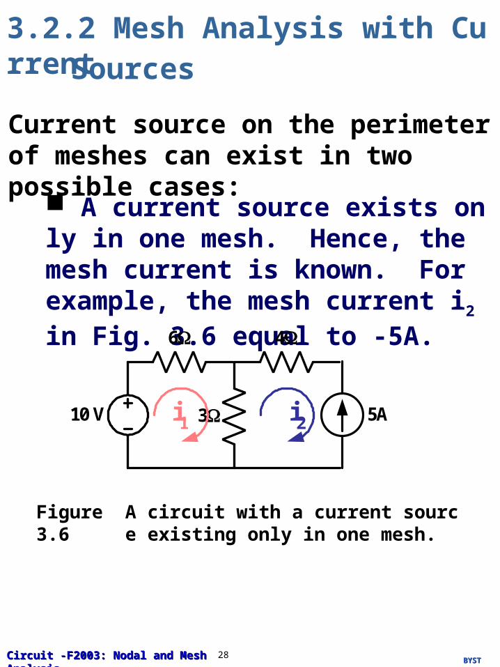
3.2.2 Mesh Analysis with CurrentSources
Current source on the perimeter of meshes can exist in two possible cases:
A current source exists only in one mesh. Hence, the mesh current is known. For example, the mesh current i2 in Fig. 3.6 equal to -5A.
Figure 3.6 A circuit with a current source existing only in one mesh.
6
10 V 3
4
5Ai1 i2
BYSTBYSTCircuit -F2003: Nodal and Mesh AnalysisCircuit -F2003: Nodal and Mesh Analysis 29
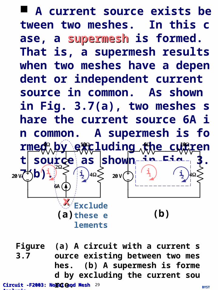
A current source exists between two meshes. In this case, a supermeshsupermesh is formed. That is, a supermesh results when two meshes have a dependent or independent current source in common. As shown in Fig. 3.7(a), two meshes share the current source 6A in common. A supermesh is formed by excluding the current source as shown in Fig. 3.7(b).
Figure 3.7 (a) A circuit with a current source existing between two meshes. (b) A supermesh is formed by excluding the current source.
6A
20 V
6
10
i1 i2 20 V
6 10
i1 i2
Exclude these elements
(a) (b)xx
BYSTBYSTCircuit -F2003: Nodal and Mesh AnalysisCircuit -F2003: Nodal and Mesh Analysis 30
A supermesh must, however, satisfy KVL similar to any other mesh. Thus, applying KVL to the supermesh in Fig. 3.7(b) yields
6i1 + 14i2 = 20
At node x x in Fig. 3.7(a), we apply KCL and get
i2 = i1 + 6
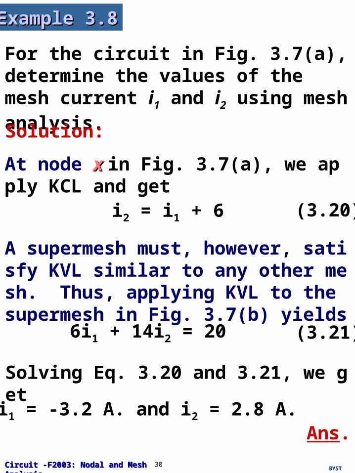
For the circuit in Fig. 3.7(a), determine the values of the mesh current i1 and i2 using mesh analysis.
Example 3.8Example 3.8
Solution:
(3.20)
(3.21)
Solving Eq. 3.20 and 3.21, we get
i1 = -3.2 A. and i2 = 2.8 A.Ans.
BYSTBYSTCircuit -F2003: Nodal and Mesh AnalysisCircuit -F2003: Nodal and Mesh Analysis 31
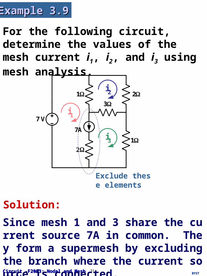
For the following circuit, determine the values of the mesh current i1, i2, and i3 using mesh analysis.
Example 3.9Example 3.9
Solution:
Since mesh 1 and 3 share the current source 7A in common. They form a supermesh by excluding the branch where the current source is connected.
Exclude these elements
7 V
13
i1
i2
2
1i3
7A
BYSTBYSTCircuit -F2003: Nodal and Mesh AnalysisCircuit -F2003: Nodal and Mesh Analysis 32
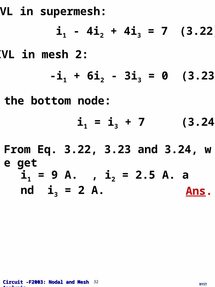
KVL in supermesh:
(3.22)i1 - 4i2 + 4i3 = 7
KVL in mesh 2:
(3.23)-i1 + 6i2 - 3i3 = 0
@ the bottom node:
(3.24)i1 = i3 + 7
From Eq. 3.22, 3.23 and 3.24, we get
i1 = 9 A. , i2 = 2.5 A. and i3 = 2 A.
Ans.
BYSTBYSTCircuit -F2003: Nodal and Mesh AnalysisCircuit -F2003: Nodal and Mesh Analysis 33
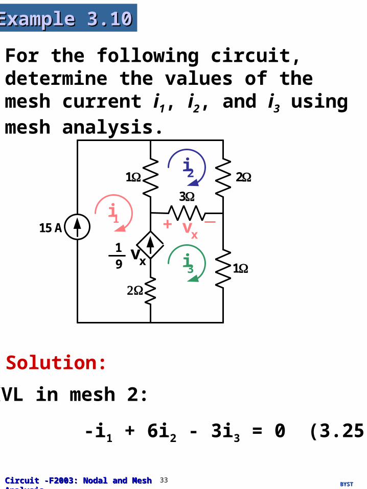
For the following circuit, determine the values of the mesh current i1, i2, and i3 using mesh analysis.
Example 3.10Example 3.10
13
i1
i2
2
1i3
15 A vx+
1 vx9
Solution:
KVL in mesh 2:
(3.25)-i1 + 6i2 - 3i3 = 0

BYSTBYSTCircuit -F2003: Nodal and Mesh AnalysisCircuit -F2003: Nodal and Mesh Analysis 34
From the given circuit, we get
(3.26)i1 = 15
and
(3.27)= i3 - i1
19
vx
Since
(3.28)vx = 3(i3 - i2)
Substitute Eq. 3.28 into 3.27, we get
(3.29)- i1 + + i3 = 013
i223
From Eq. 3.25, 3.26 and 3.29, we get
i1 = 15 A. , i2 = 11 A. and i3 = 17 A.
Ans.