Embed Size (px)
Citation preview
Metal Finishing Wastewater Treatment
Presented by: David Calnan & CCI- A Chemical Corporation
Metal Finishing Wastewater Treatment Overview
• Why treat wastewater • Sources of wastewater • Waste disposal options • Conventional on-site treatment methods
– Physical treatment – Chemical treatment
• Trouble shooting • Questions and answers
Metal Finishing WWT Why Treat?
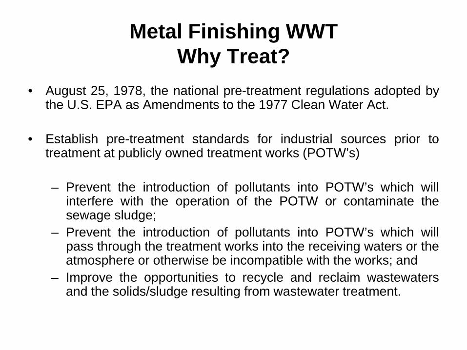
• August 25, 1978, the national pre-treatment regulations adopted by the U.S. EPA as Amendments to the 1977 Clean Water Act.
• Establish pre-treatment standards for industrial sources prior to
treatment at publicly owned treatment works (POTW’s)
– Prevent the introduction of pollutants into POTW’s which will interfere with the operation of the POTW or contaminate the sewage sludge;
– Prevent the introduction of pollutants into POTW’s which will pass through the treatment works into the receiving waters or the atmosphere or otherwise be incompatible with the works; and
– Improve the opportunities to recycle and reclaim wastewaters and the solids/sludge resulting from wastewater treatment.
Metal Finishing WWT Why Treat?
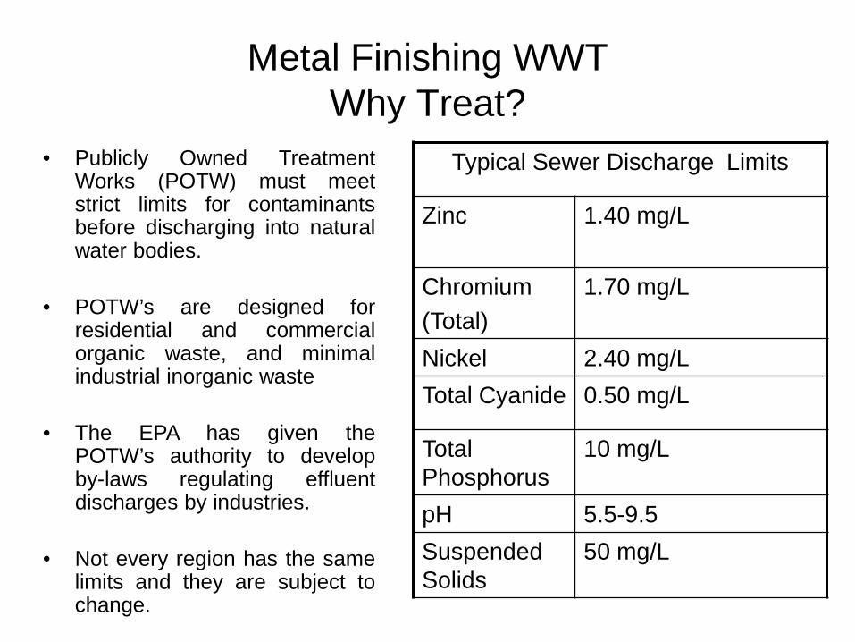
• Publicly Owned Treatment Works (POTW) must meet strict limits for contaminants before discharging into natural water bodies.
• POTW’s are designed for residential and commercial organic waste, and minimal industrial inorganic waste
• The EPA has given the POTW’s authority to develop by-laws regulating effluent discharges by industries.
• Not every region has the same limits and they are subject to change.
Typical Sewer Discharge Limits
Zinc 1.40 mg/L
Chromium (Total)
1.70 mg/L
Nickel 2.40 mg/L Total Cyanide 0.50 mg/L
Total Phosphorus
10 mg/L
pH 5.5-9.5 Suspended Solids
50 mg/L
Metal Finishing WWT Sources
• Metal finishing processes generate waste – Process baths age
• Incoming oils/rust inhibitors. • Metal by-products sloughing off parts. • Secondary reactions creating contaminants.
– Rinses contaminated with carryover • Solution is carried (drag out) from one tank to the
next. • Increased demands on production increases drag
out.
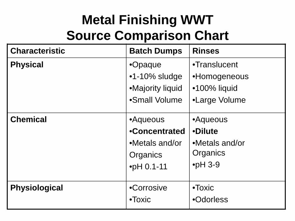
Metal Finishing WWT Source Comparison Chart
Characteristic Batch Dumps Rinses Physical •Opaque
•1-10% sludge •Majority liquid •Small Volume
•Translucent •Homogeneous •100% liquid •Large Volume
Chemical •Aqueous •Concentrated •Metals and/or Organics •pH 0.1-11
•Aqueous •Dilute •Metals and/or Organics •pH 3-9
Physiological •Corrosive •Toxic
•Toxic •Odorless
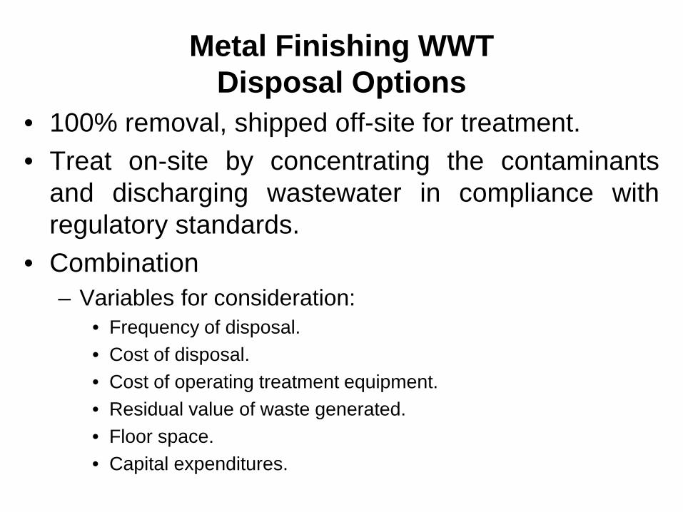
Metal Finishing WWT Disposal Options
• 100% removal, shipped off-site for treatment. • Treat on-site by concentrating the contaminants
and discharging wastewater in compliance with regulatory standards.
• Combination – Variables for consideration:
• Frequency of disposal. • Cost of disposal. • Cost of operating treatment equipment. • Residual value of waste generated. • Floor space. • Capital expenditures.
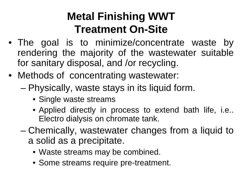
Metal Finishing WWT Treatment On-Site
• The goal is to minimize/concentrate waste by rendering the majority of the wastewater suitable for sanitary disposal, and /or recycling.
• Methods of concentrating wastewater: – Physically, waste stays in its liquid form.
• Single waste streams • Applied directly in process to extend bath life, i.e..
Electro dialysis on chromate tank. – Chemically, wastewater changes from a liquid to
a solid as a precipitate. • Waste streams may be combined. • Some streams require pre-treatment.
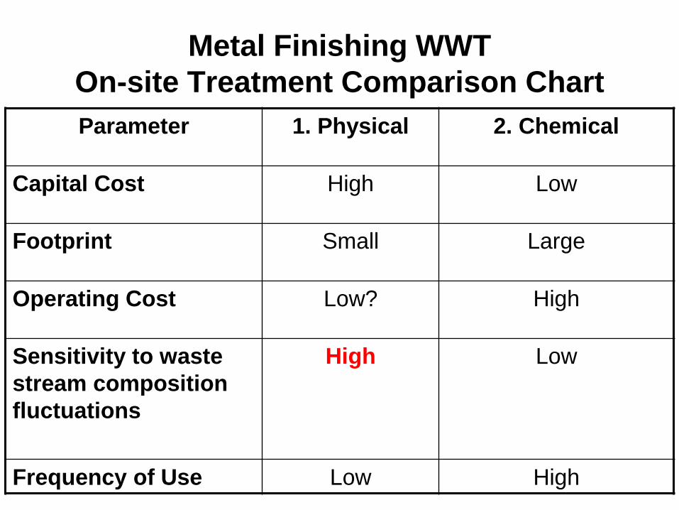
Metal Finishing WWT On-site Treatment Comparison Chart Parameter 1. Physical 2. Chemical
Capital Cost High Low
Footprint Small Large
Operating Cost Low? High
Sensitivity to waste stream composition fluctuations
High Low
Frequency of Use Low High
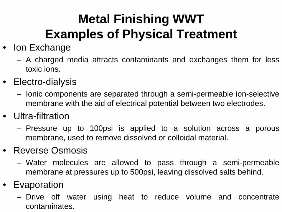
Metal Finishing WWT Examples of Physical Treatment
• Ion Exchange – A charged media attracts contaminants and exchanges them for less
toxic ions.
• Electro-dialysis – Ionic components are separated through a semi-permeable ion-selective
membrane with the aid of electrical potential between two electrodes.
• Ultra-filtration – Pressure up to 100psi is applied to a solution across a porous
membrane, used to remove dissolved or colloidal material.
• Reverse Osmosis – Water molecules are allowed to pass through a semi-permeable
membrane at pressures up to 500psi, leaving dissolved salts behind.
• Evaporation – Drive off water using heat to reduce volume and concentrate
contaminates.
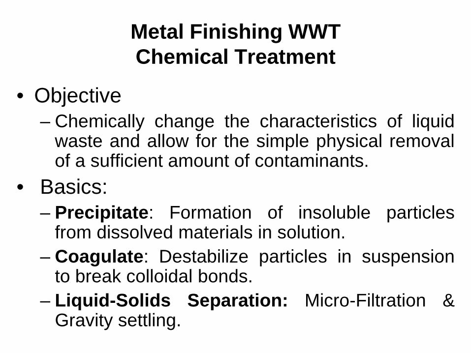
Metal Finishing WWT Chemical Treatment
• Objective – Chemically change the characteristics of liquid
waste and allow for the simple physical removal of a sufficient amount of contaminants.
• Basics: – Precipitate: Formation of insoluble particles
from dissolved materials in solution. – Coagulate: Destabilize particles in suspension
to break colloidal bonds. – Liquid-Solids Separation: Micro-Filtration &
Gravity settling.
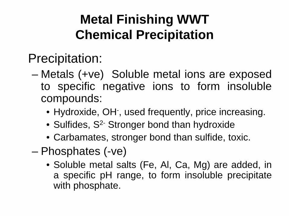
Metal Finishing WWT Chemical Precipitation
Precipitation: – Metals (+ve) Soluble metal ions are exposed
to specific negative ions to form insoluble compounds:
• Hydroxide, OH-, used frequently, price increasing. • Sulfides, S2- Stronger bond than hydroxide • Carbamates, stronger bond than sulfide, toxic.
– Phosphates (-ve) • Soluble metal salts (Fe, Al, Ca, Mg) are added, in
a specific pH range, to form insoluble precipitate with phosphate.
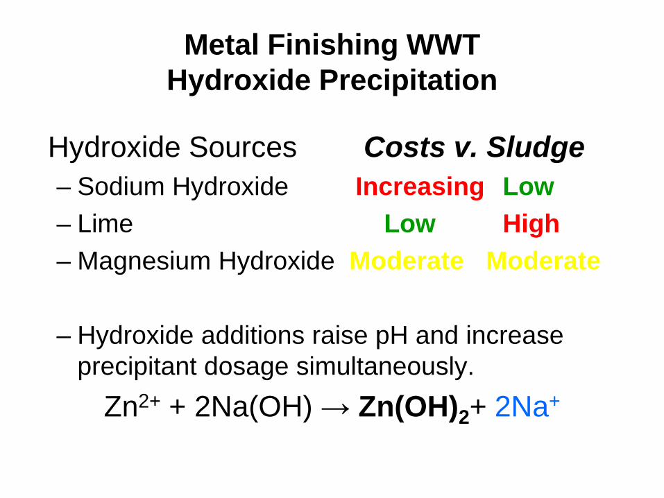
Metal Finishing WWT Hydroxide Precipitation
Hydroxide Sources Costs v. Sludge – Sodium Hydroxide Increasing Low – Lime Low High – Magnesium Hydroxide Moderate Moderate
– Hydroxide additions raise pH and increase
precipitant dosage simultaneously. Zn2+ + 2Na(OH) → Zn(OH)2+ 2Na+
Metal Finishing WWT Hydroxide Precipitation
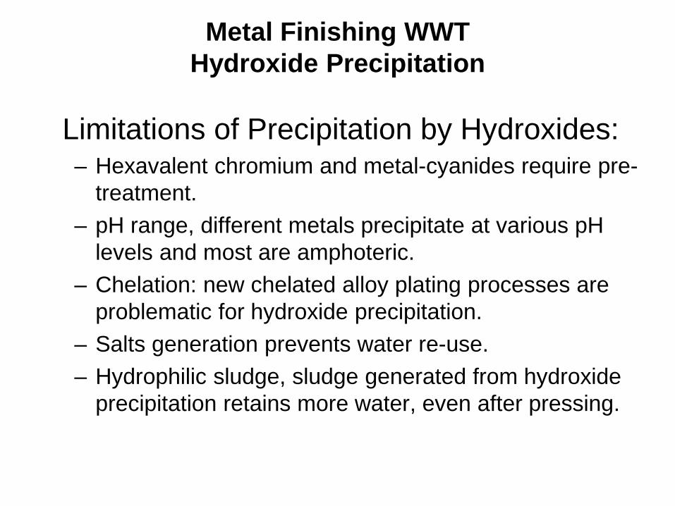
Limitations of Precipitation by Hydroxides:
– Hexavalent chromium and metal-cyanides require pre-treatment.
– pH range, different metals precipitate at various pH levels and most are amphoteric.
– Chelation: new chelated alloy plating processes are problematic for hydroxide precipitation.
– Salts generation prevents water re-use. – Hydrophilic sludge, sludge generated from hydroxide
precipitation retains more water, even after pressing.

Metal Finishing WWT Chemical Precipitation
Hydroxide Precipitation Chart
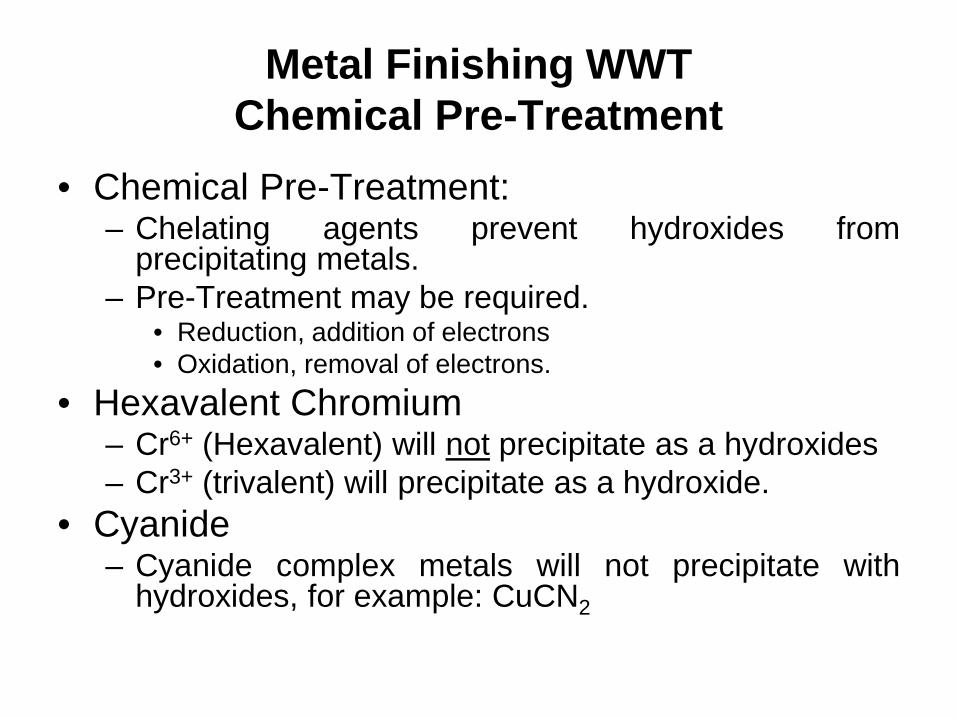
Metal Finishing WWT Chemical Pre-Treatment
• Chemical Pre-Treatment: – Chelating agents prevent hydroxides from
precipitating metals. – Pre-Treatment may be required.
• Reduction, addition of electrons • Oxidation, removal of electrons.
• Hexavalent Chromium – Cr6+ (Hexavalent) will not precipitate as a hydroxides – Cr3+ (trivalent) will precipitate as a hydroxide.
• Cyanide – Cyanide complex metals will not precipitate with
hydroxides, for example: CuCN2
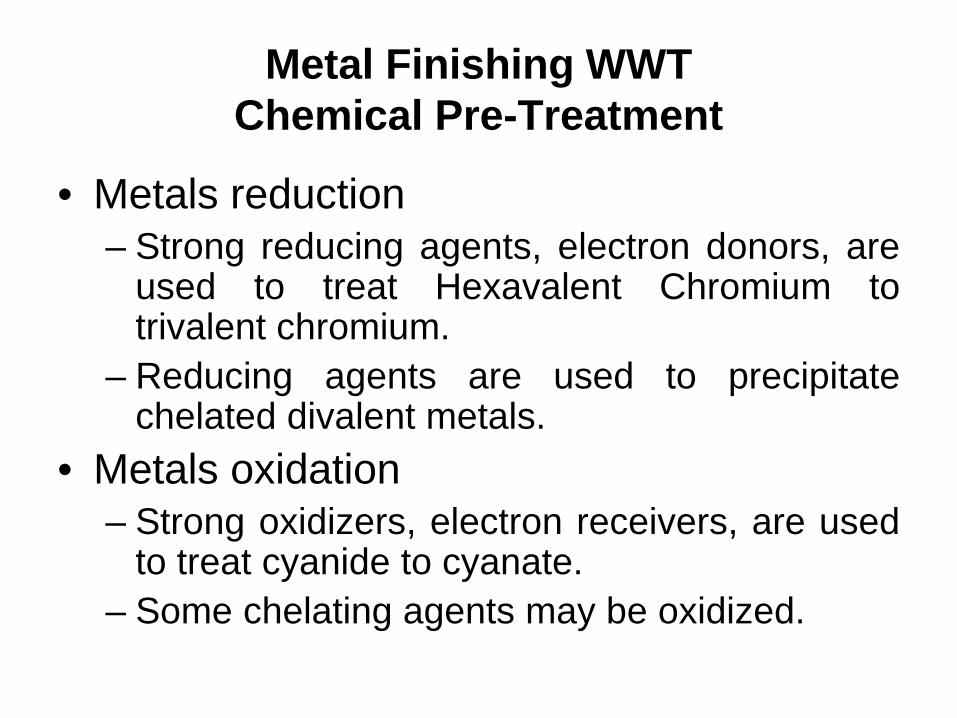
Metal Finishing WWT Chemical Pre-Treatment
• Metals reduction – Strong reducing agents, electron donors, are
used to treat Hexavalent Chromium to trivalent chromium.
– Reducing agents are used to precipitate chelated divalent metals.
• Metals oxidation – Strong oxidizers, electron receivers, are used
to treat cyanide to cyanate. – Some chelating agents may be oxidized.
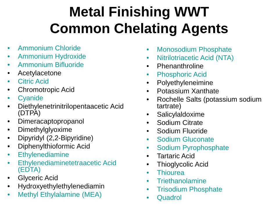
Metal Finishing WWT Common Chelating Agents
• Monosodium Phosphate • Nitrilotriacetic Acid (NTA) • Phenanthroline • Phosphoric Acid • Polyethyleneimine • Potassium Xanthate • Rochelle Salts (potassium sodium
tartrate) • Salicylaldoxime • Sodium Citrate • Sodium Fluoride • Sodium Gluconate • Sodium Pyrophosphate • Tartaric Acid • Thioglycolic Acid • Thiourea • Triethanolamine • Trisodium Phosphate • Quadrol
• Ammonium Chloride • Ammonium Hydroxide • Ammonium Bifluoride • Acetylacetone • Citric Acid • Chromotropic Acid • Cyanide • Diethylenetrinitrilopentaacetic Acid
(DTPA) • Dimeracaptopropanol • Dimethylglyoxime • Dipyridyl (2,2-Bipyridine) • Diphenylthioformic Acid • Ethylenediamine • Ethylenediaminetetraacetic Acid
(EDTA) • Glyceric Acid • Hydroxyethylethylenediamin • Methyl Ethylalamine (MEA)
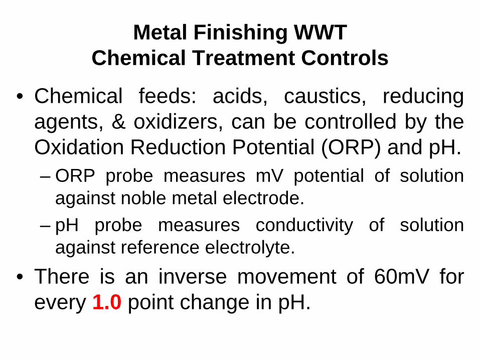
Metal Finishing WWT Chemical Treatment Controls
• Chemical feeds: acids, caustics, reducing agents, & oxidizers, can be controlled by the Oxidation Reduction Potential (ORP) and pH. – ORP probe measures mV potential of solution
against noble metal electrode. – pH probe measures conductivity of solution
against reference electrolyte. • There is an inverse movement of 60mV for
every 1.0 point change in pH.
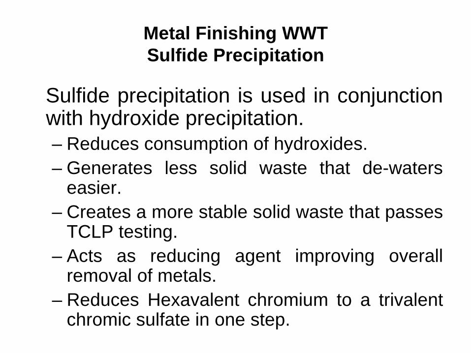
Metal Finishing WWT Sulfide Precipitation
Sulfide precipitation is used in conjunction with hydroxide precipitation. – Reduces consumption of hydroxides. – Generates less solid waste that de-waters
easier. – Creates a more stable solid waste that passes
TCLP testing. – Acts as reducing agent improving overall
removal of metals. – Reduces Hexavalent chromium to a trivalent
chromic sulfate in one step.
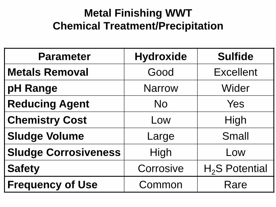
Metal Finishing WWT Chemical Treatment/Precipitation
Parameter Hydroxide Sulfide
Metals Removal Good Excellent pH Range Narrow Wider Reducing Agent No Yes Chemistry Cost Low High Sludge Volume Large Small Sludge Corrosiveness High Low Safety Corrosive H2S Potential Frequency of Use Common Rare
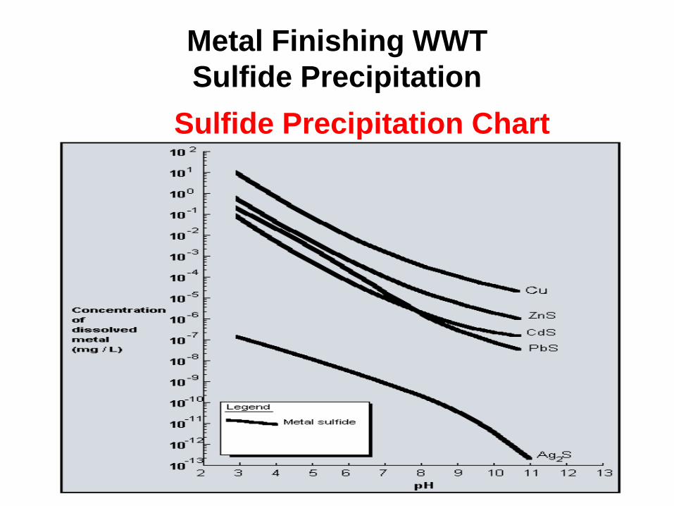
Metal Finishing WWT Sulfide Precipitation
Sulfide Precipitation Chart
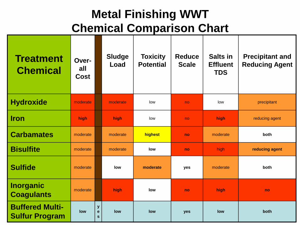
Metal Finishing WWT Chemical Comparison Chart
Treatment Chemical
Over-
all Cost
Sludge Load
Toxicity Potential
Reduce Scale
Salts in Effluent
TDS
Precipitant and Reducing Agent
Hydroxide moderate moderate low no low precipitant
Iron high high low no high reducing agent
Carbamates moderate moderate highest no moderate both
Bisulfite moderate moderate low no high reducing agent
Sulfide moderate low moderate yes moderate both
Inorganic Coagulants
moderate high low no high no
Buffered Multi-Sulfur Program
low yes
low low yes low both
Metal Finishing WWT Chemical Treatment/Coagulation
Coagulation of Colloids and Precipitates
– Coagulation is the de-stabilization of colloidal particles.
– Colloid or Colloidal Dispersion: • A form of matter suspended between a true solution and a
mixture. • Microscopic particles of one substance said to be distributed
through the solvent phase of another.
– Characteristics of Colloids: • Sizes range from 0.001 to 1 micrometers. • Slow to very slow settling rate (.5m/hr – 0.5m/yr.) • Colloids may be colored or translucent.
Metal Finishing WWT Chemical Treatment/Coagulation
• Types of Colloids
– Hydrophilic colloids. • Responsible for coloring water. • Typically organic creating hydrogen bonds with water
molecules. – Hydrophobic colloids
• Mineral in nature • Negatively charged surfaces generate a mutual repulsion,
making agglomeration impossible
• Elimination of Colloids: achieved by an addition of an agglomerating agent (coagulant) that neutralizes the electro-static charge.
Metal Finishing WWT Coagulation
Coagulant Basics:
– Characteristics • Mineral or organic • Always cationic with a strong density of charge • Low to very low molecular weight
– Main Groups • Polyamines • PolyDADMAC • Metal Salts (FeCl2, CaCl2, PAC) • Organo-Metalic blends
Metal Finishing WWT Coagulants
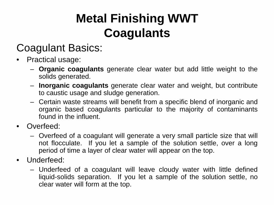
Coagulant Basics: • Practical usage:
– Organic coagulants generate clear water but add little weight to the solids generated.
– Inorganic coagulants generate clear water and weight, but contribute to caustic usage and sludge generation.
– Certain waste streams will benefit from a specific blend of inorganic and organic based coagulants particular to the majority of contaminants found in the influent.
• Overfeed: – Overfeed of a coagulant will generate a very small particle size that will
not flocculate. If you let a sample of the solution settle, over a long period of time a layer of clear water will appear on the top.
• Underfeed: – Underfeed of a coagulant will leave cloudy water with little defined
liquid-solids separation. If you let a sample of the solution settle, no clear water will form at the top.
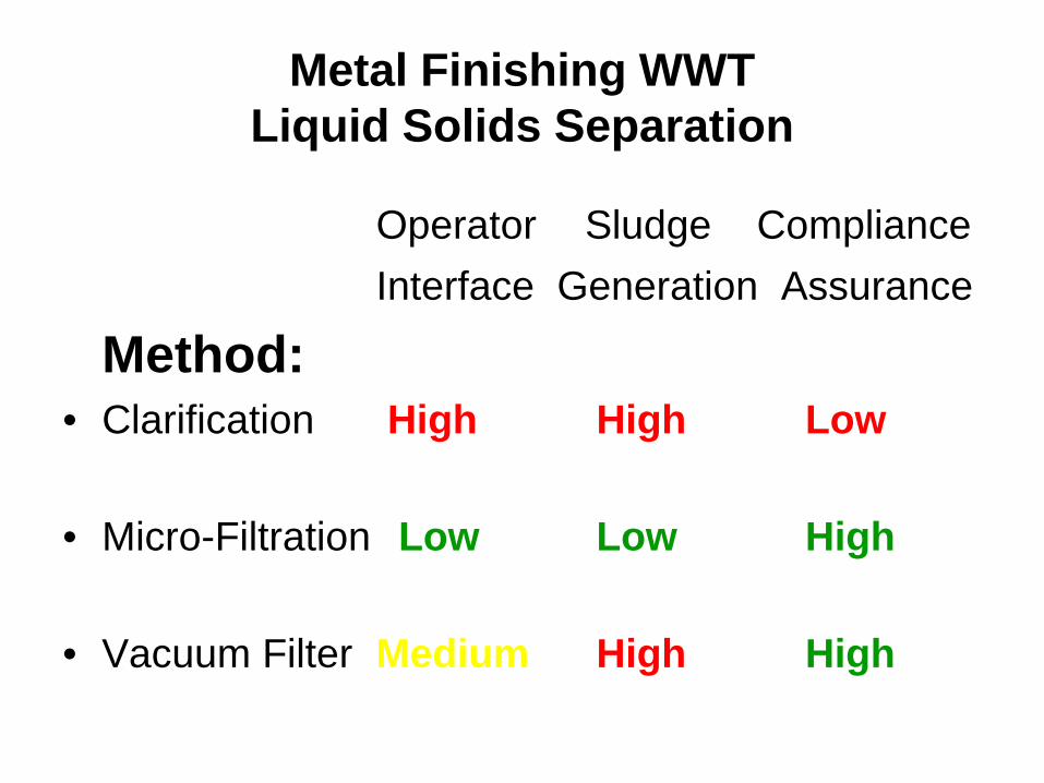
Metal Finishing WWT Liquid Solids Separation
Operator Sludge Compliance Interface Generation Assurance
Method: • Clarification High High Low • Micro-Filtration Low Low High
• Vacuum Filter Medium High High
Metal Finishing WWT Liquid-Solids Separation
Clarification or Gravity Settling: – A solids loading must be maintained at proper levels:
• Lamella recommends that 10% of the overall flow-rate be constantly drawn off the bottom of the clarifier.
• 20% solids should be maintained in the clarifier to promote “up-flow filtration.”
– Take a sample from the middle port/spigot on the bottom of the clarifier and let the solids settle for 2-hours. There should be approximately 20% solids by volume in the sample for proper “up-flow filtration.”
– Clarifiers can accumulate scale causing the channeling of solids that elevate TSS.
• Sulfamic acid is recommended as a safe and economical method for removing scale from Clarifiers.
Metal Finishing WWT Liquid-Solids Separation
Clarification or Gravity Settling requires flocculation with a high molecular weight anionic or cationic polymer. – Polymer make-up:
• Run the Polymer Feed Tank as low is as feasibly possible. • Add the undiluted polymer to the mixing tank when the mixer is just
covered by water, let mix for 5-10-minutes, the fill. • Diluted polymer should stretch between 1” and 2” before breaking.
– Polymer feed rate: • A sample taken from the flocculation tank should have the solids
settling in a slight mound. • If the solids settle with a peak, or a in a ball, the polymer is overfed.
– Excess polymer generates cloudy water and wet filter press dumps. • If the solids settle flat , or concave, the polymer is underfed.
– Underfed polymer increases Total Suspended Solids (TSS.)
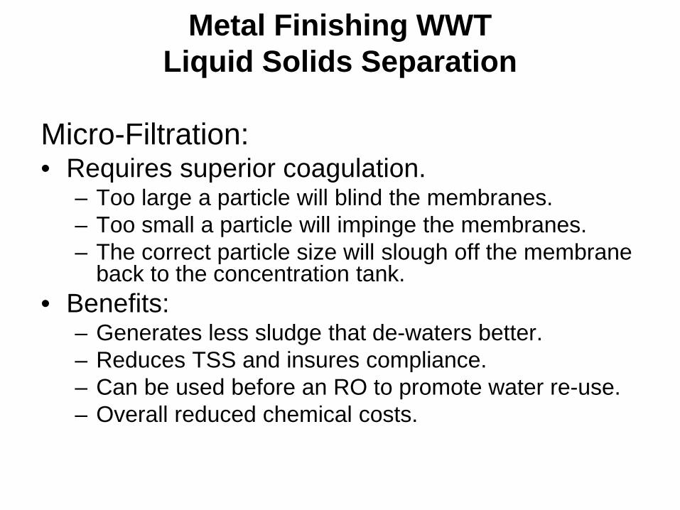
Metal Finishing WWT Liquid Solids Separation
Micro-Filtration: • Requires superior coagulation.
– Too large a particle will blind the membranes. – Too small a particle will impinge the membranes. – The correct particle size will slough off the membrane
back to the concentration tank. • Benefits:
– Generates less sludge that de-waters better. – Reduces TSS and insures compliance. – Can be used before an RO to promote water re-use. – Overall reduced chemical costs.
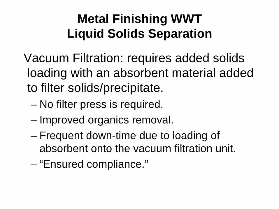
Metal Finishing WWT Liquid Solids Separation
Vacuum Filtration: requires added solids loading with an absorbent material added to filter solids/precipitate. – No filter press is required. – Improved organics removal. – Frequent down-time due to loading of
absorbent onto the vacuum filtration unit. – “Ensured compliance.”
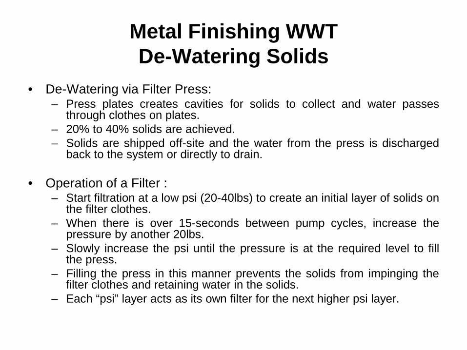
Metal Finishing WWT De-Watering Solids
• De-Watering via Filter Press: – Press plates creates cavities for solids to collect and water passes
through clothes on plates. – 20% to 40% solids are achieved. – Solids are shipped off-site and the water from the press is discharged
back to the system or directly to drain.
• Operation of a Filter : – Start filtration at a low psi (20-40lbs) to create an initial layer of solids on
the filter clothes. – When there is over 15-seconds between pump cycles, increase the
pressure by another 20lbs. – Slowly increase the psi until the pressure is at the required level to fill
the press. – Filling the press in this manner prevents the solids from impinging the
filter clothes and retaining water in the solids. – Each “psi” layer acts as its own filter for the next higher psi layer.
Metal Finishing WWT Trouble Shooting
• Excessive solids in the system • High metals levels in the effluent • Suspended solids in the effluent • Cleaner & Concentrate treatments • Ground loop faults • Poor equalization • Operator training/documentation • Housekeeping
Metal Finishing WWT Trouble Shooting
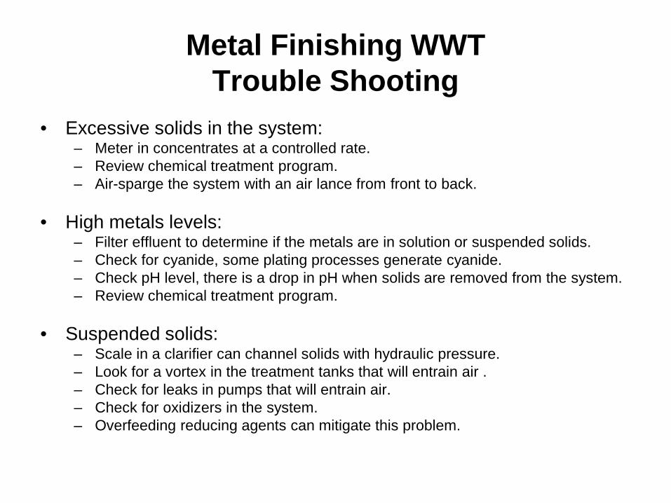
• Excessive solids in the system: – Meter in concentrates at a controlled rate. – Review chemical treatment program. – Air-sparge the system with an air lance from front to back.
• High metals levels: – Filter effluent to determine if the metals are in solution or suspended solids. – Check for cyanide, some plating processes generate cyanide. – Check pH level, there is a drop in pH when solids are removed from the system. – Review chemical treatment program.
• Suspended solids: – Scale in a clarifier can channel solids with hydraulic pressure. – Look for a vortex in the treatment tanks that will entrain air . – Check for leaks in pumps that will entrain air. – Check for oxidizers in the system. – Overfeeding reducing agents can mitigate this problem.
Metal Finishing WWT Trouble Shooting
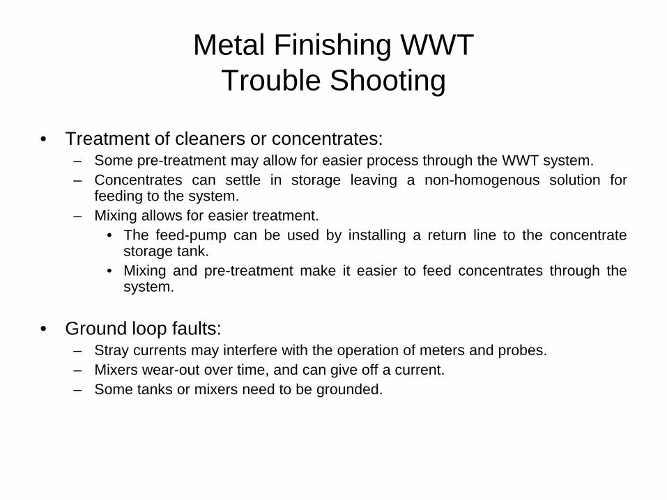
• Treatment of cleaners or concentrates:
– Some pre-treatment may allow for easier process through the WWT system. – Concentrates can settle in storage leaving a non-homogenous solution for
feeding to the system. – Mixing allows for easier treatment.
• The feed-pump can be used by installing a return line to the concentrate storage tank.
• Mixing and pre-treatment make it easier to feed concentrates through the system.
• Ground loop faults: – Stray currents may interfere with the operation of meters and probes. – Mixers wear-out over time, and can give off a current. – Some tanks or mixers need to be grounded.
Metal Finishing WWT Trouble Shooting
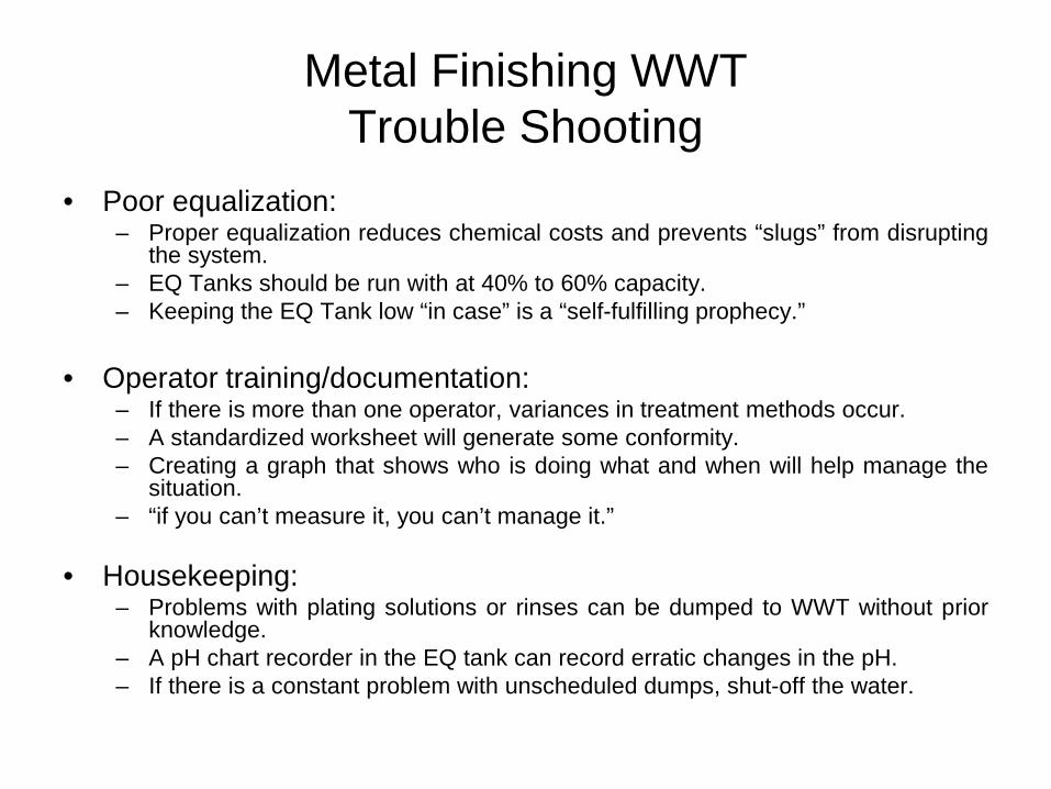
• Poor equalization:
– Proper equalization reduces chemical costs and prevents “slugs” from disrupting the system.
– EQ Tanks should be run with at 40% to 60% capacity. – Keeping the EQ Tank low “in case” is a “self-fulfilling prophecy.”
• Operator training/documentation:
– If there is more than one operator, variances in treatment methods occur. – A standardized worksheet will generate some conformity. – Creating a graph that shows who is doing what and when will help manage the
situation. – “if you can’t measure it, you can’t manage it.”
• Housekeeping: – Problems with plating solutions or rinses can be dumped to WWT without prior
knowledge. – A pH chart recorder in the EQ tank can record erratic changes in the pH. – If there is a constant problem with unscheduled dumps, shut-off the water.