Embed Size (px)
Citation preview
Institute of Structural Engineering Page 1
Method of Finite Elements I
Chapter 2b
2nd order Effects & Structural Dynamics:Modal Analysis with the DSM
Method of Finite Elements I
Institute of Structural Engineering Page 2
Method of Finite Elements I
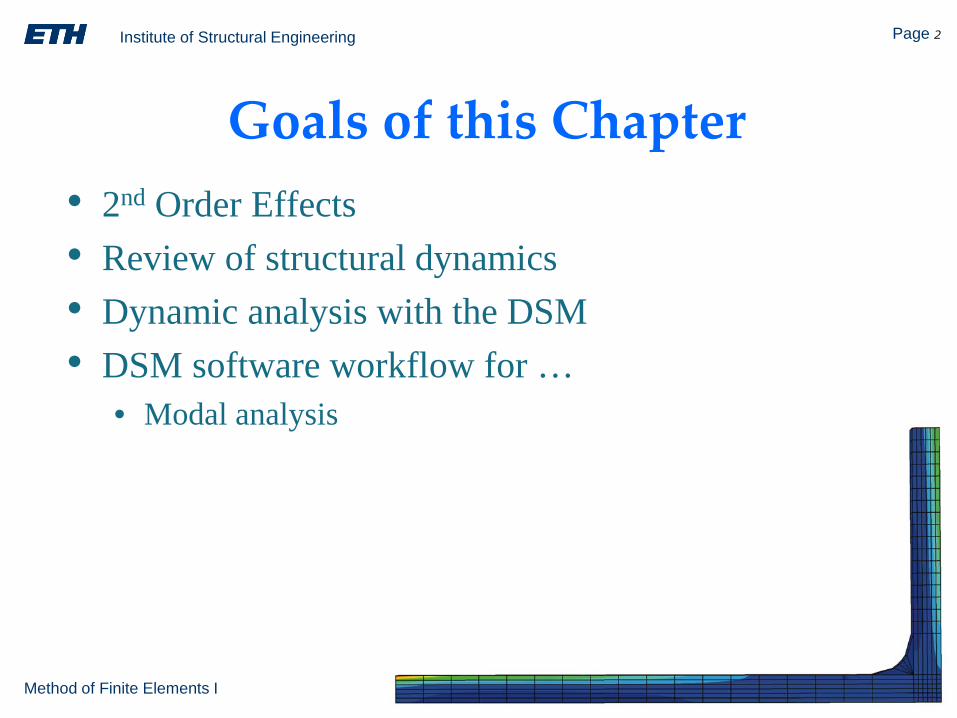
Goals of this Chapter• 2nd Order Effects• Review of structural dynamics• Dynamic analysis with the DSM• DSM software workflow for …
• Modal analysis
Institute of Structural Engineering Page 3
Method of Finite Elements I
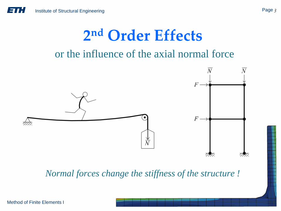
2nd Order Effectsor the influence of the axial normal force
Normal forces change the stiffness of the structure !
Institute of Structural Engineering Page 4
Method of Finite Elements I
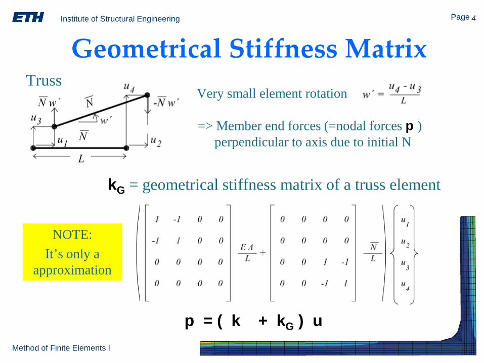
Geometrical Stiffness Matrix
kG = geometrical stiffness matrix of a truss element
p = ( k + kG ) u
Very small element rotation
=> Member end forces (=nodal forces p )perpendicular to axis due to initial N
Truss
NOTE:It’s only a
approximation
Institute of Structural Engineering Page 5
Method of Finite Elements I
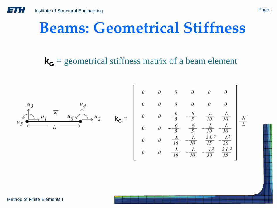
Beams: Geometrical Stiffness
kG = geometrical stiffness matrix of a beam element
kG =
Institute of Structural Engineering Page 6
Method of Finite Elements I
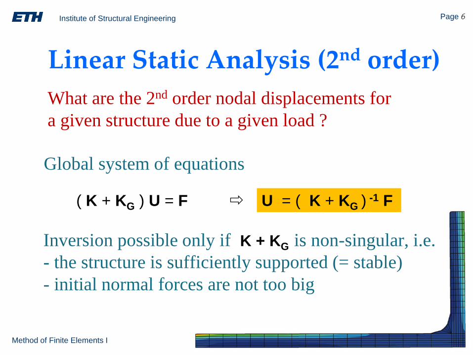
Linear Static Analysis (2nd order)
Global system of equations
( K + KG ) U = F U = ( K + KG ) -1 F
Inversion possible only if K + KG is non-singular, i.e.- the structure is sufficiently supported (= stable)- initial normal forces are not too big
What are the 2nd order nodal displacements fora given structure due to a given load ?
Institute of Structural Engineering Page 7
Method of Finite Elements I
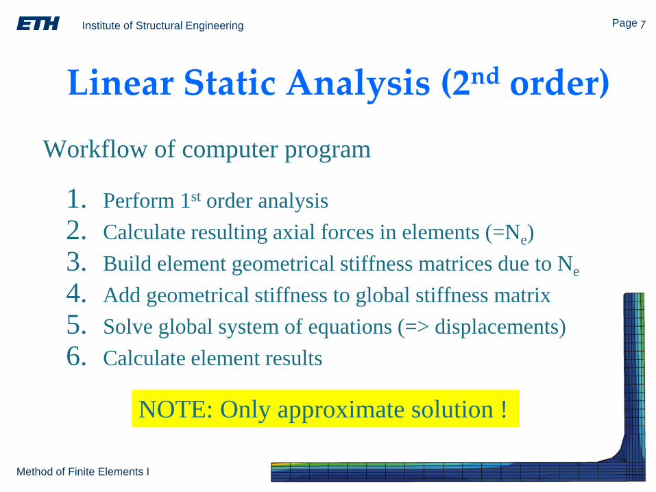
Linear Static Analysis (2nd order)
Workflow of computer program
1. Perform 1st order analysis2. Calculate resulting axial forces in elements (=Ne)3. Build element geometrical stiffness matrices due to Ne
4. Add geometrical stiffness to global stiffness matrix5. Solve global system of equations (=> displacements)6. Calculate element results
NOTE: Only approximate solution !
Institute of Structural Engineering Page 8
Method of Finite Elements I
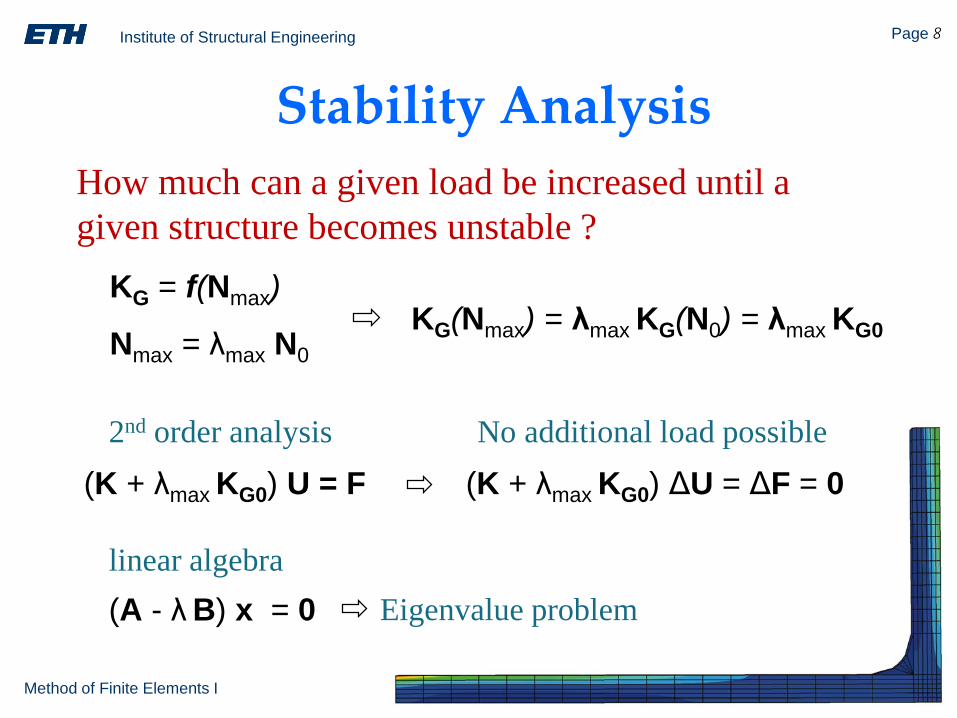
Stability AnalysisHow much can a given load be increased until a given structure becomes unstable ?
(K + λmax KG0) U = F
Nmax = λmax N0
KG = f(Nmax)KG(Nmax) = λmax KG(N0) = λmax KG0
2nd order analysis No additional load possible(K + λmax KG0) ΔU = ΔF = 0
linear algebra(A - λ B) x = 0 Eigenvalue problem
Institute of Structural Engineering Page 9
Method of Finite Elements I
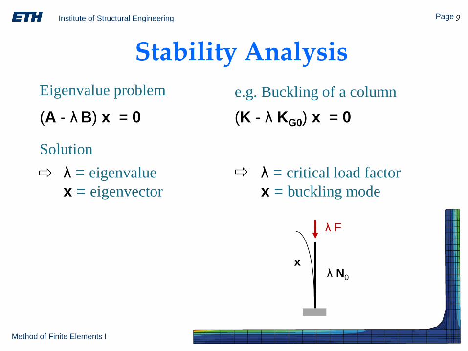
Stability AnalysisEigenvalue problem
(A - λ B) x = 0
λ = eigenvaluex = eigenvector
(K - λ KG0) x = 0
λ = critical load factorx = buckling mode
e.g. Buckling of a column
λ N0
λ F
x
Solution
Institute of Structural Engineering Page 10
Method of Finite Elements I
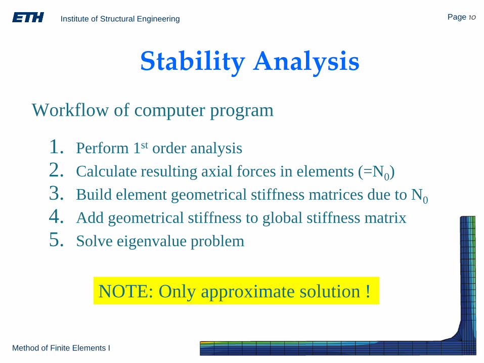
Stability Analysis
Workflow of computer program
1. Perform 1st order analysis2. Calculate resulting axial forces in elements (=N0)3. Build element geometrical stiffness matrices due to N0
4. Add geometrical stiffness to global stiffness matrix5. Solve eigenvalue problem
NOTE: Only approximate solution !
Institute of Structural Engineering Page 11
Method of Finite Elements I
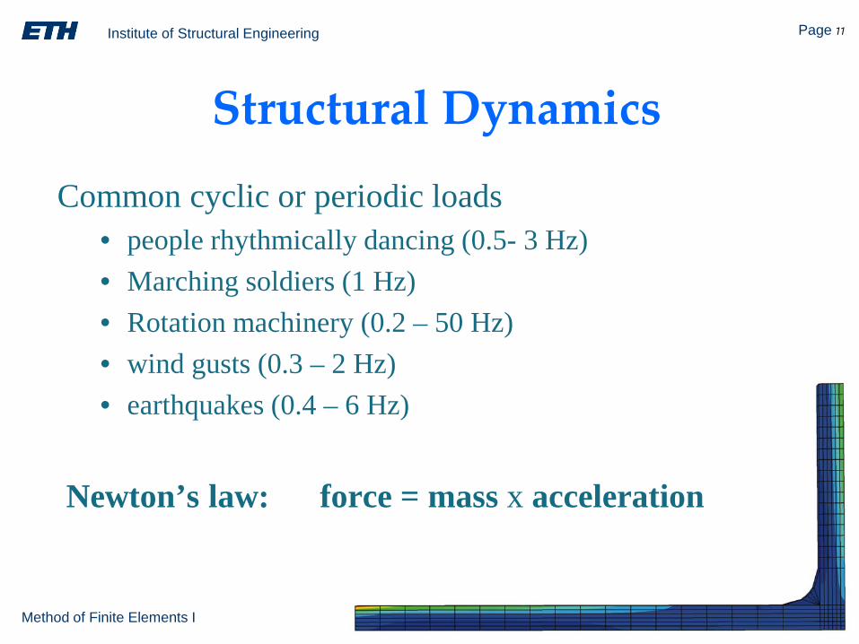
Newton’s law: force = mass x acceleration
Common cyclic or periodic loads• people rhythmically dancing (0.5- 3 Hz)• Marching soldiers (1 Hz)• Rotation machinery (0.2 – 50 Hz)• wind gusts (0.3 – 2 Hz)• earthquakes (0.4 – 6 Hz)
Structural Dynamics
Institute of Structural Engineering Page 12
Method of Finite Elements I
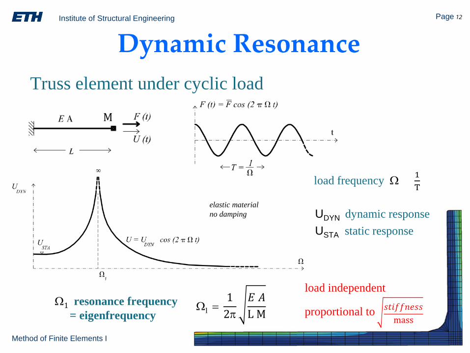
Dynamic ResonanceTruss element under cyclic load
load frequency Ω = 1T
UDYN dynamic responseUSTA static response
Ω1 resonance frequency= eigenfrequency
Ω1 =1
2π𝐸𝐸 𝐴𝐴L M
load independent
elastic materialno damping
M
𝑠𝑠𝑠𝑠𝑠𝑠𝑠𝑠𝑠𝑠𝑠𝑠𝑠𝑠𝑠𝑠𝑠𝑠mass
proportional to
Institute of Structural Engineering Page 13
Method of Finite Elements I
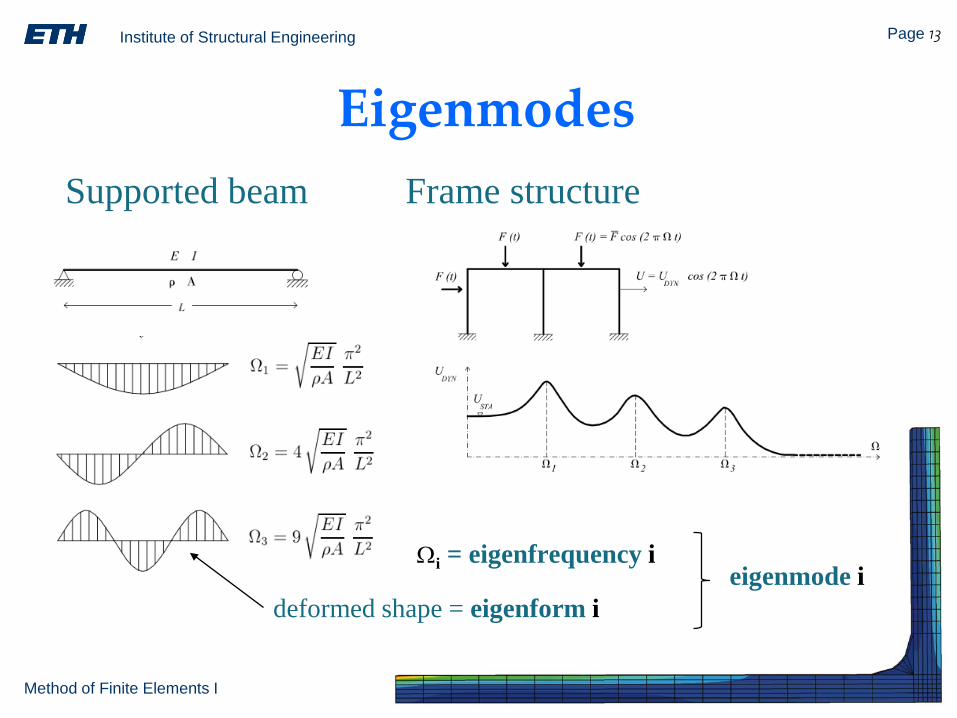
EigenmodesFrame structureSupported beam
deformed shape = eigenform i
Ωi = eigenfrequency ieigenmode i
Institute of Structural Engineering Page 14
Method of Finite Elements I
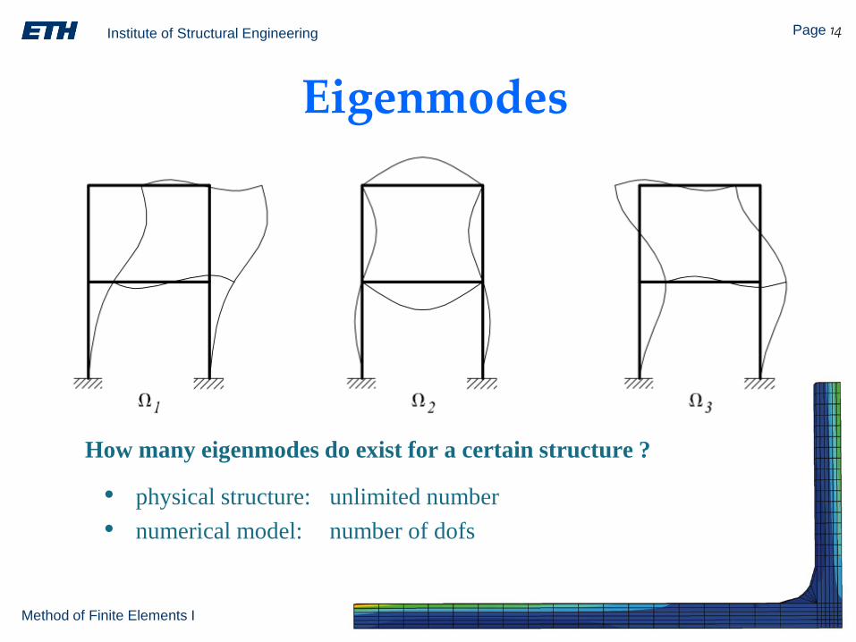
Eigenmodes
• physical structure: unlimited number• numerical model: number of dofs
How many eigenmodes do exist for a certain structure ?
Institute of Structural Engineering Page 15
Method of Finite Elements I
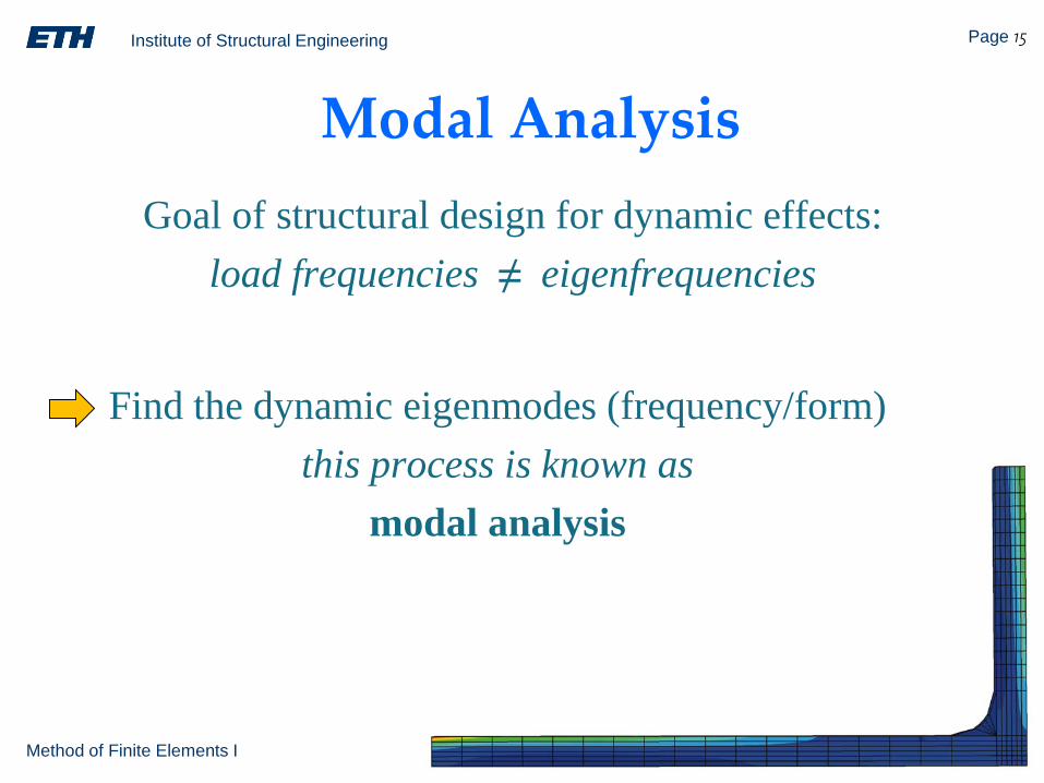
Modal AnalysisGoal of structural design for dynamic effects:
load frequencies ≠ eigenfrequencies
Find the dynamic eigenmodes (frequency/form)this process is known as
modal analysis
Institute of Structural Engineering Page 16
Method of Finite Elements I
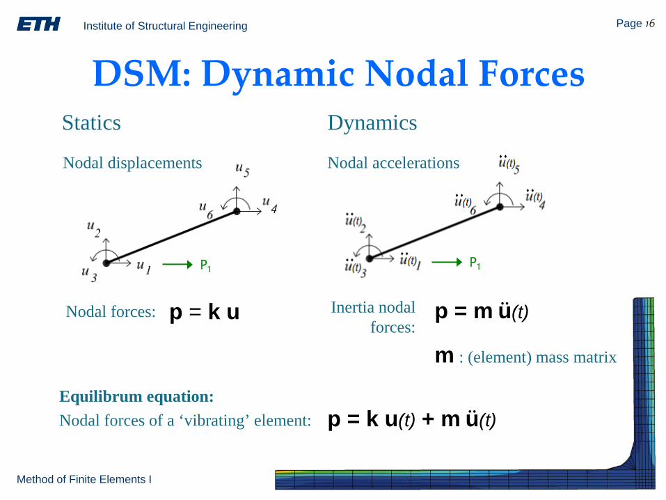
DSM: Dynamic Nodal Forces
P1 P1
p = k u p = m u(t)
Statics Dynamics
Inertia nodal forces:
Nodal displacements Nodal accelerations
p = k u(t) + m u(t)Equilibrum equation:Nodal forces of a ‘vibrating’ element:
m : (element) mass matrix
Nodal forces:
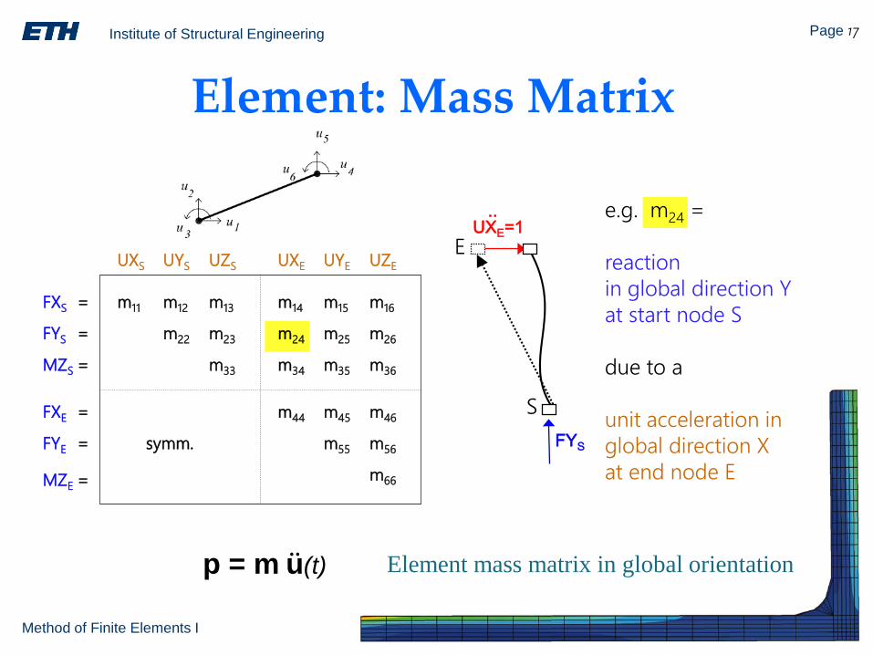
Institute of Structural Engineering Page 17
Method of Finite Elements I
UXE=1
FYS
S
E..
FXS =
FYS =
MZS =
FXE =
FYE =
MZE =
UXS UYS UZS UXE UYE UZE
m14 m15 m16
m24 m25 m26
m34 m35 m36
m44 m45 m46
m55 m56
m66
m11 m12 m13
m22 m23
m33
symm.
e.g. m24 =
reactionin global direction Yat start node S
due to a
unit acceleration in global direction Xat end node E
Element: Mass Matrix
p = m u(t) Element mass matrix in global orientation
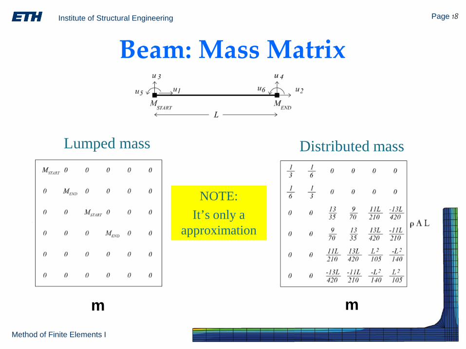
Institute of Structural Engineering Page 18
Method of Finite Elements I
Beam: Mass Matrix
m m
Lumped mass Distributed mass
NOTE:It’s only a
approximation
Institute of Structural Engineering Page 19
Method of Finite Elements I
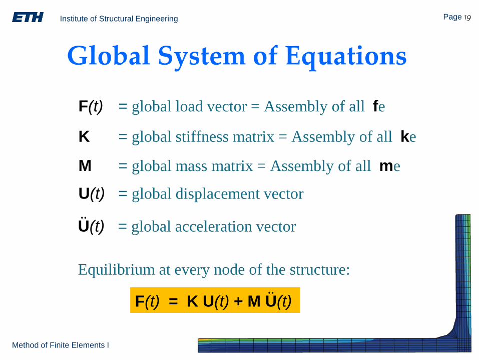
K = global stiffness matrix = Assembly of all ke
F(t) = K U(t) + M U(t)
Global System of Equations
Equilibrium at every node of the structure:
F(t) = global load vector = Assembly of all fe
U(t) = global displacement vector
M = global mass matrix = Assembly of all me
U(t) = global acceleration vector
Institute of Structural Engineering Page 20
Method of Finite Elements I
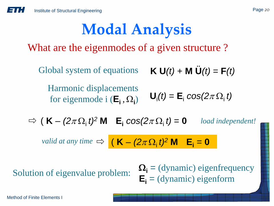
Modal AnalysisWhat are the eigenmodes of a given structure ?
Global system of equations K U(t) + M U(t) = F(t)
Harmonic displacementsfor eigenmode i (Ei ,Ωi) Ui(t) = Ei cos(2π Ωi t)
( K – (2π Ωi t)2 M ) Ei cos(2π Ωi t) = 0
valid at any time ( K – (2π Ωi t)2 M ) Ei = 0
Solution of eigenvalue problem: Ωi = (dynamic) eigenfrequencyEi = (dynamic) eigenform
load independent!
Institute of Structural Engineering Page 21
Method of Finite Elements I
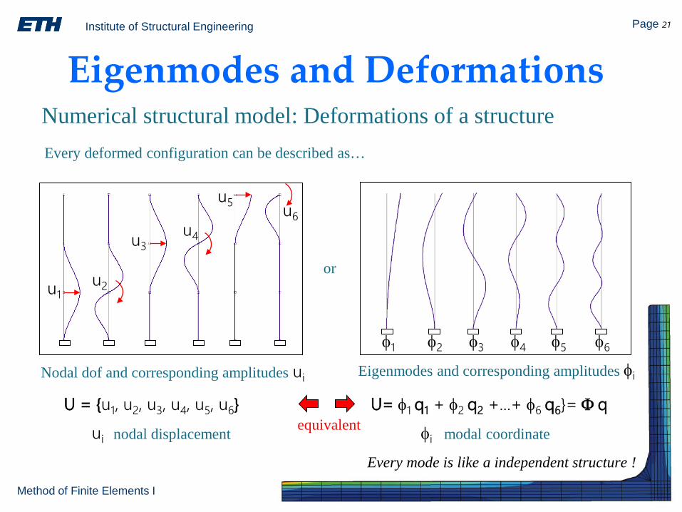
Eigenmodes and DeformationsNumerical structural model: Deformations of a structure
U = u1, u2, u3, u4, u5, u6
u1u2
u3u4
u5 u6
φ1 φ2 φ3 φ4 φ5 φ6
Every deformed configuration can be described as…
Nodal dof and corresponding amplitudes Eigenmodes and corresponding amplitudes
U= φ1 q1 + φ2 q2 +...+ φ6 q6= Φ q
or
ui nodal displacement
ui φi
φi modal coordinateequivalent
Every mode is like a independent structure !
Institute of Structural Engineering Page 22
Method of Finite Elements I
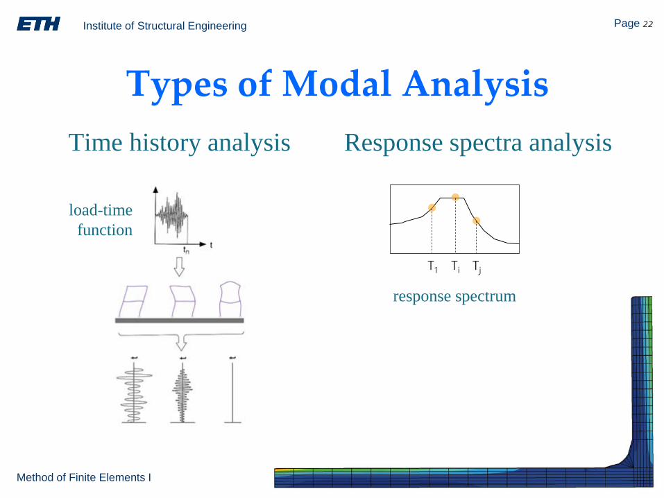
Types of Modal AnalysisResponse spectra analysis Time history analysis
load-timefunction
T1 Ti Tj
response spectrum
Institute of Structural Engineering Page 23
Method of Finite Elements I
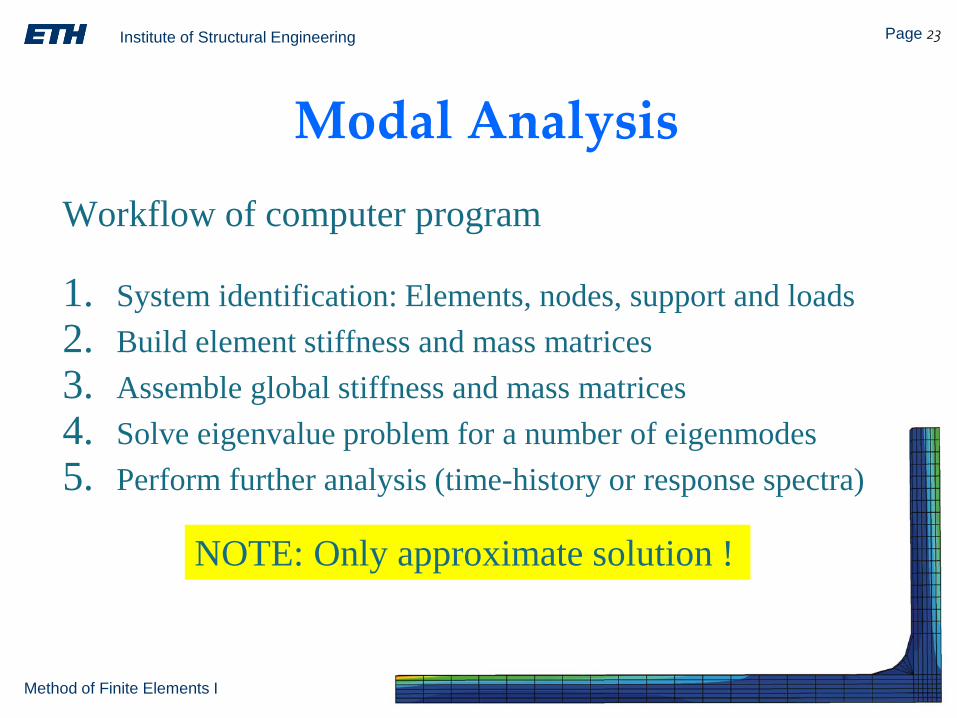
Modal AnalysisWorkflow of computer program
1. System identification: Elements, nodes, support and loads2. Build element stiffness and mass matrices3. Assemble global stiffness and mass matrices4. Solve eigenvalue problem for a number of eigenmodes5. Perform further analysis (time-history or response spectra)
NOTE: Only approximate solution !


![Chapter 7 · Institute of Structural Engineering Page 1 Method of Finite Elements I Chapter 7. 2D Elements. Book Chapters [O] V1/Ch4 & Ch6](https://img.pdfslide.net/doc/110x75/5ecfcc65ada1ab22ed0e6c1c/chapter-7-institute-of-structural-engineering-page-1-method-of-finite-elements-i.jpg)