Embed Size (px)
Citation preview
MFS, MPO4/8/12-Fiber connectors
and Fan-Out assemblies
MFS, MPO and Fan-Out
INTRODUCTION

IntroductionMT ferrule construction
➔ MT plastic multi-fiber ferrule are aligned via 2 precision guide
pins and mated trough style adapters. Physical contact of the mating surface is ensured trough integrated springs located behind the ferrule.
8-fibers MT ferrule 24-fibers MT ferrule (2 rows of 12)

IntroductionFactors affecting physical contact
➔ Standard MT ferrules can accommodate up to 24 fibers and are manufactured with tight tolerances aimed at controlling the 3 main geometric factors that impact optical performances.
d: Transverse offsetθ: Fiber angles: Air gap
Transverse offset is the most influential and isimpacted by the following: Clearance between fiber holes and fibers Clearance between guide holes and guide pins Fiber holes and fiber core eccentricity Alignment between fiber holes axis and guide holes axis
IntroductionFactors affecting physical contact
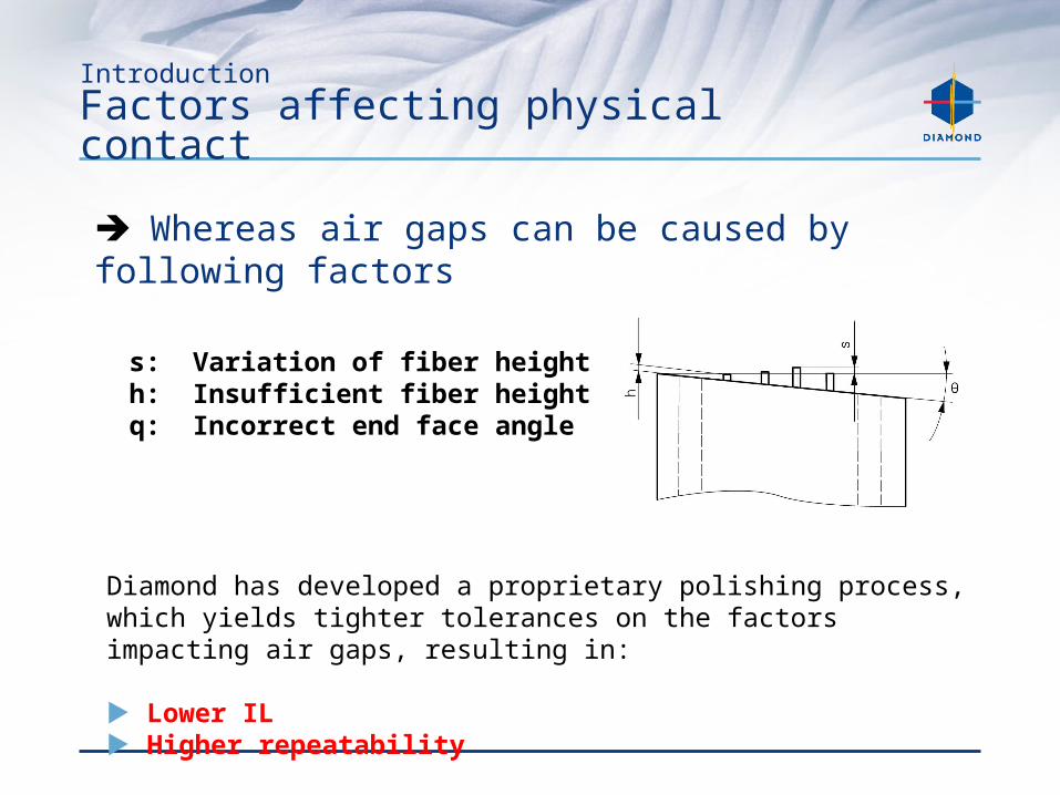
➔ Whereas air gaps can be caused by following factors
s: Variation of fiber heighth: Insufficient fiber heightq: Incorrect end face angle
Diamond has developed a proprietary polishing process, which yields tighter tolerances on the factors impacting air gaps, resulting in:
Lower IL Higher repeatability
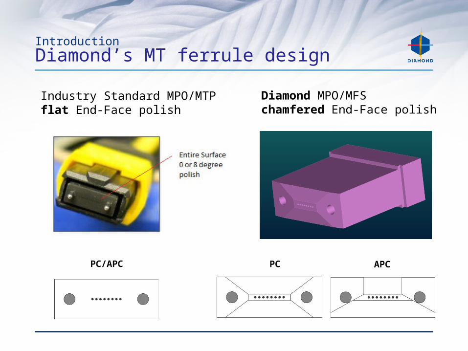
IntroductionDiamond’s MT ferrule design
Industry Standard MPO/MTP flat End-Face polish
Diamond MPO/MFS chamfered End-Face polish
PC/APC PC APC
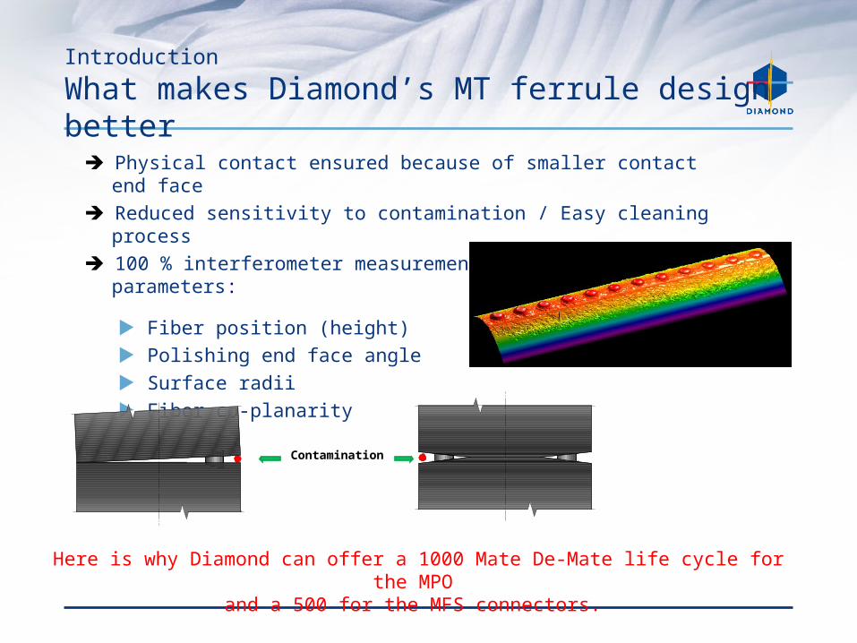
Introduction
What makes Diamond’s MT ferrule design better
Here is why Diamond can offer a 1000 Mate De-Mate life cycle for the MPO and a 500 for the MFS connectors.
➔ Physical contact ensured because of smaller contact end face➔ Reduced sensitivity to contamination / Easy cleaning process➔ 100 % interferometer measurement of relevant surface
parameters:
Fiber position (height) Polishing end face angle Surface radii Fiber co-planarity
Contamination
MFS, MPO and Fan-Out
PRODUCTS
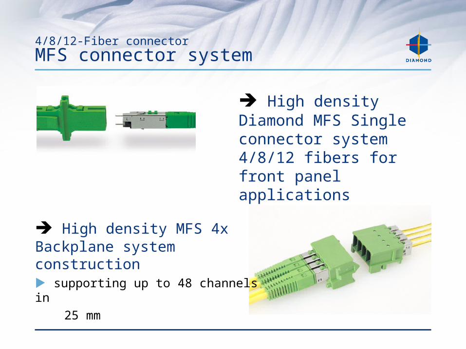
4/8/12-Fiber connectorMFS connector system
➔ High density MFS 4x Backplane system construction supporting up to 48 channels in 25 mm
➔ High density Diamond MFS Single connector system 4/8/12 fibers for front panel applications
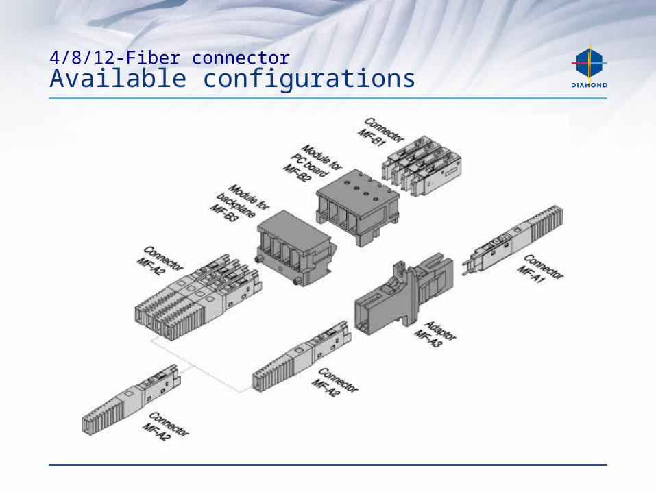
4/8/12-Fiber connectorAvailable configurations
4/8/12-Fiber connector
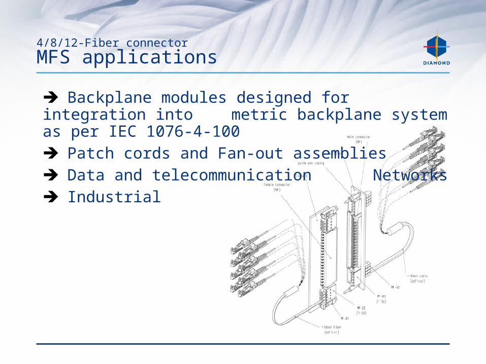
MFS applications
➔ Backplane modules designed for integration into metric backplane system as per IEC 1076-4-100
➔ Patch cords and Fan-out assemblies➔ Data and telecommunication
Networks➔ Industrial
4/8/12-Fiber connector MFS features and benefits
➔ Each single connector supports up to 12 fiberslow cost per termination for high density applications
➔ Active Push-pull mechanismeasy of operation
➔ Suitable pre-guiding trackshigh repeatability and stability
➔ Precision molded MT ferrule and advanced polishing process
Lower IL and higher repeatability
➔ EN 186310 and TIA/EIA 604-15

4/8/12-Fiber connector
MPO connector
➔ Diamond MPO high-densitymulti-fiber connector system basedon MT ferrule.
➔ Available in 4,8 and 12 fiber versions, PC and APC finishes, for both MM and SM applications
4/8/12-Fiber connector
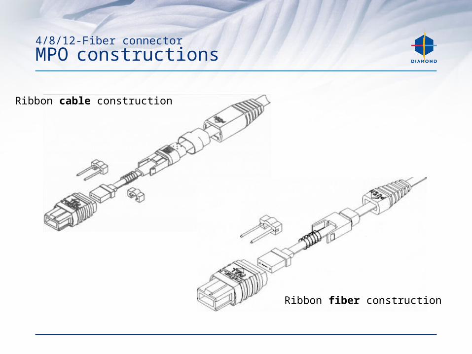
MPO constructions
Ribbon fiber construction
Ribbon cable construction
4/8/12-Fiber connector MPO applications
➔ Patch cords and Fan-Out assemblies➔ ATM and DWDM high speed communication systems
➔ Multimedia
➔ CATV and Video
➔ Data Telecommunication Networks
➔ Industrial
4/8/12-Fiber connector MPO features and benefits
➔ Support up to 12 fiberslow cost per termination for high density applications
➔ Push-pull mechanismeasy of operation
➔ Precision molded MT ferrule and advanced polishing process
lower IL and higher repeatability
➔ IEC 61754-7 and TIA/EIA 604-5A compliant
4/8/12-Fiber connector
MFS and MPO typical values
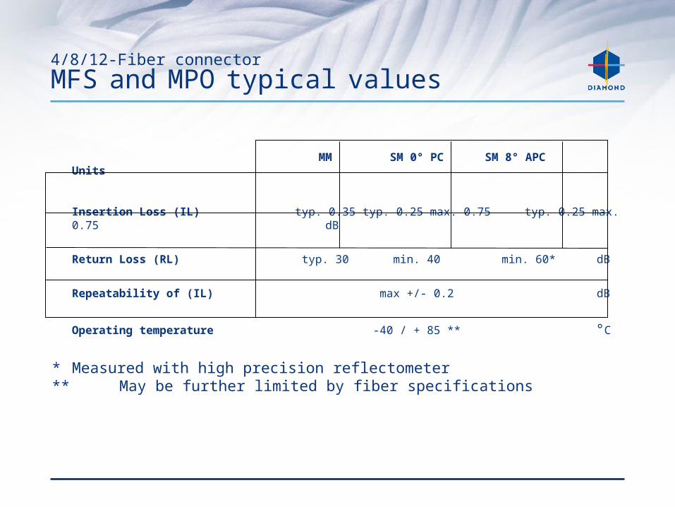
MM SM 0° PC SM 8° APC Units
Insertion Loss (IL) typ. 0.35 typ. 0.25 max. 0.75 typ. 0.25 max. 0.75 dB
Return Loss (RL) typ. 30 min. 40 min. 60* dB
Repeatability of (IL) max +/- 0.2 dB
Operating temperature -40 / + 85 ** °C
* Measured with high precision reflectometer** May be further limited by fiber specifications
4/8/12-fibers Fan-Out assemblies
Introduction
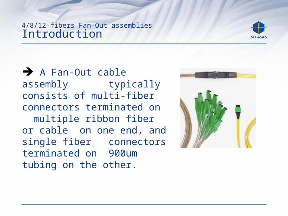
➔ A Fan-Out cable assembly typically consists of multi-fiber connectors terminated on multiple ribbon fiber or cable on one end, and single fiber connectors terminated on 900um tubing on the other.
4/8/12-fibers Fan-Out assemblies
Available configurations
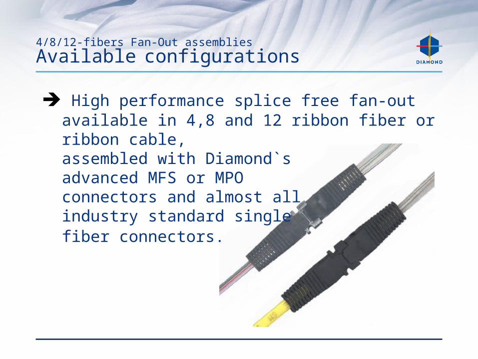
➔ High performance splice free fan-out available in 4,8 and 12 ribbon fiber or ribbon cable,assembled with Diamond`sadvanced MFS or MPOconnectors and almost allindustry standard singlefiber connectors.

4/8/12- fibers Fan-Out assemblies Applications
➔ Used to facilitate the conversion from the ribbon to individual fiber format➔ High density channel routing between equipment and interconnect racks
➔ Termination of outside plant cable at the customer demarcation point
4/8/12- fibers Fan-Out assemblies Features and benefits
➔ High density multi-fiber design4,8 or 12 channel ribbon fiber or ribbon cable
➔ Compact designeasily stacked and secured for high-density applications
➔ Strain relief boots superior bend radius protection resulting in higherreliability
➔ Available in different lengths to support custom applications
4/8/12-fibers Fan-Out assemblies
Typical values
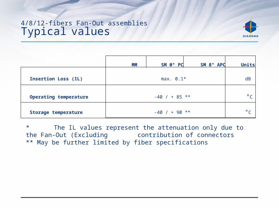
MM SM 0° PC SM 8° APC Units
Insertion Loss (IL) max. 0.1* dB
Operating temperature -40 / + 85 ** °C
Storage temperature -40 / + 90 ** °C
* The IL values represent the attenuation only due to the Fan-Out (Excluding contribution of connectors** May be further limited by fiber specifications