Embed Size (px)
Citation preview

2013 Microchip Technology Inc. DS41681A
MGC3130 Aurea
Graphical User Interface
User’s Guide

DS41681A-page 2 2013 Microchip Technology Inc.
Information contained in this publication regarding deviceapplications and the like is provided only for your convenienceand may be superseded by updates. It is your responsibility toensure that your application meets with your specifications.MICROCHIP MAKES NO REPRESENTATIONS ORWARRANTIES OF ANY KIND WHETHER EXPRESS ORIMPLIED, WRITTEN OR ORAL, STATUTORY OROTHERWISE, RELATED TO THE INFORMATION,INCLUDING BUT NOT LIMITED TO ITS CONDITION,QUALITY, PERFORMANCE, MERCHANTABILITY ORFITNESS FOR PURPOSE. Microchip disclaims all liabilityarising from this information and its use. Use of Microchipdevices in life support and/or safety applications is entirely atthe buyer’s risk, and the buyer agrees to defend, indemnify andhold harmless Microchip from any and all damages, claims,suits, or expenses resulting from such use. No licenses areconveyed, implicitly or otherwise, under any Microchipintellectual property rights.
Note the following details of the code protection feature on Microchip devices:
• Microchip products meet the specification contained in their particular Microchip Data Sheet.
• Microchip believes that its family of products is one of the most secure families of its kind on the market today, when used in the intended manner and under normal conditions.
• There are dishonest and possibly illegal methods used to breach the code protection feature. All of these methods, to our knowledge, require using the Microchip products in a manner outside the operating specifications contained in Microchip’s Data Sheets. Most likely, the person doing so is engaged in theft of intellectual property.
• Microchip is willing to work with the customer who is concerned about the integrity of their code.
• Neither Microchip nor any other semiconductor manufacturer can guarantee the security of their code. Code protection does not mean that we are guaranteeing the product as “unbreakable.”
Code protection is constantly evolving. We at Microchip are committed to continuously improving the code protection features of ourproducts. Attempts to break Microchip’s code protection feature may be a violation of the Digital Millennium Copyright Act. If such actsallow unauthorized access to your software or other copyrighted work, you may have a right to sue for relief under that Act.
Microchip received ISO/TS-16949:2009 certification for its worldwide headquarters, design and wafer fabrication facilities in Chandler and Tempe, Arizona; Gresham, Oregon and design centers in California and India. The Company’s quality system processes and procedures are for its PIC® MCUs and dsPIC® DSCs, KEELOQ® code hopping devices, Serial EEPROMs, microperipherals, nonvolatile memory and analog products. In addition, Microchip’s quality system for the design and manufacture of development systems is ISO 9001:2000 certified.
QUALITY MANAGEMENT SYSTEM CERTIFIED BY DNV
== ISO/TS 16949 ==
Trademarks
The Microchip name and logo, the Microchip logo, dsPIC, FlashFlex, KEELOQ, KEELOQ logo, MPLAB, PIC, PICmicro, PICSTART, PIC32 logo, rfPIC, SST, SST Logo, SuperFlash and UNI/O are registered trademarks of Microchip Technology Incorporated in the U.S.A. and other countries.
FilterLab, Hampshire, HI-TECH C, Linear Active Thermistor, MTP, SEEVAL and The Embedded Control Solutions Company are registered trademarks of Microchip Technology Incorporated in the U.S.A.
Silicon Storage Technology is a registered trademark of Microchip Technology Inc. in other countries.
Analog-for-the-Digital Age, Application Maestro, BodyCom, chipKIT, chipKIT logo, CodeGuard, dsPICDEM, dsPICDEM.net, dsPICworks, dsSPEAK, ECAN, ECONOMONITOR, FanSense, HI-TIDE, In-Circuit Serial Programming, ICSP, Mindi, MiWi, MPASM, MPF, MPLAB Certified logo, MPLIB, MPLINK, mTouch, Omniscient Code Generation, PICC, PICC-18, PICDEM, PICDEM.net, PICkit, PICtail, REAL ICE, rfLAB, Select Mode, SQI, Serial Quad I/O, Total Endurance, TSHARC, UniWinDriver, WiperLock, ZENA and Z-Scale are trademarks of Microchip Technology Incorporated in the U.S.A. and other countries.
SQTP is a service mark of Microchip Technology Incorporated in the U.S.A.
GestIC and ULPP are registered trademarks of Microchip Technology Germany II GmbH & Co. & KG, a subsidiary of Microchip Technology Inc., in other countries.
All other trademarks mentioned herein are property of their respective companies.
© 2013, Microchip Technology Incorporated, Printed in the U.S.A., All Rights Reserved.
Printed on recycled paper.
ISBN: 9781620770078

MGC3130 AUREAGRAPHICAL USER INTERFACE
USER’S GUIDE
Table of Contents
Chapter 1. Overview1.1 Introduction ................................................................................................... 11
1.1.1 Aurea Start Up ........................................................................................... 11
1.2 Aurea Graphical User Interface .................................................................... 121.2.1 Visualization Tabs ..................................................................................... 121.2.2 Real Time Control .................................................................................... 12
1.2.2.1 Context Sensitive Elements ....................................................... 121.2.2.2 Static Menu Elements ............................................................... 13
1.2.3 Status Bar ................................................................................................. 14
Chapter 2. Aurea Visualization Tabs2.1 Colibri Suite ................................................................................................. 15
2.1.1 Colibri Suite Visualization Tab ................................................................... 152.1.1.1 XY and XYZ Position Tracking Plots ......................................... 162.1.1.2 Signal Level ............................................................................... 172.1.1.3 History Logging .......................................................................... 172.1.1.4 Gesture Indication .................................................................... 17
2.1.2 Colibri Suite Real Time Control ................................................................ 172.1.2.1 Gestures .................................................................................... 172.1.2.2 Applications ............................................................................... 192.1.2.3 Feature Control .......................................................................... 20
2.2 Signals .......................................................................................................... 212.2.1 Signals Visualization Tab .......................................................................... 212.2.2 Signals Real Time Control ........................................................................ 22
2.2.2.1 Channels ................................................................................... 222.2.2.2 Levels ........................................................................................ 222.2.2.3 Autocalibration Checkbox .......................................................... 222.2.2.4 Approach Detection / Power Saving Checkbox ......................... 232.2.2.5 Lock Zoom Level Checkbox ...................................................... 232.2.2.6 Freeze ....................................................................................... 232.2.2.7 Signal Type Dropdown List ........................................................ 232.2.2.8 Automatic Frequency Hopping Dropdown List .......................... 232.2.2.9 Force Calibration Button ............................................................ 23
2.3 Setup ........................................................................................................... 242.3.1 Setup Visualization Tab ............................................................................. 242.3.2 Setup Real Time Control ........................................................................... 25
2.3.2.1 Analog Front end Settings ......................................................... 252.3.2.2 GestIC Library Update ............................................................... 26
2013 Microchip Technology Inc. DS41681A-page 3

Table of Contents
Chapter 3. Advanced Aurea Features3.1 Logging Sensor Data ................................................................................... 27
3.1.1 Record a Log File ...................................................................................... 273.1.2 Log File Content and Format .................................................................... 27
3.2 Sensitivity Profile Acquisition ........................................................................ 293.2.1 Sensor Calibration ..................................................................................... 293.2.2 Measurement ............................................................................................ 30
Appendix A. Glossary
2013 Microchip Technology Inc. DS41681A-page 4

MGC3130 AUREAGRAPHICAL USER
INTERFACE USER’S GUIDE
Preface
INTRODUCTION
This chapter contains general information that will be useful to know before using the Chapter Name. Items discussed in this chapter include:
• Document Layout
• Conventions Used in this Guide
• Warranty Registration
• Recommended Reading
• The Microchip Web Site
• Development Systems Customer Change Notification Service
• Customer Support
• Document Revision History
DOCUMENT LAYOUT
This document describes the installation and use of the Chapter Name. Microchip’s Aurea is a Windows® based graphical user interface that can be used to demonstrate, evaluate and configure Microchip’s MGC3130 3D tracking and Gesture Controller. The document is organized as follows:
• Chapter 1. “Overview”
• Chapter 2. “Aurea Visualization Tabs”
• Chapter 3. “Advanced Aurea Features”
• Appendix A. “Glossary”
NOTICE TO CUSTOMERS
All documentation becomes dated, and this manual is no exception. Microchip tools and documentation are constantly evolving to meet customer needs, so some actual dialogs and/or tool descriptions may differ from those in this document. Please refer to our web site (www.microchip.com) to obtain the latest documentation available.
Documents are identified with a “DS” number. This number is located on the bottom of each page, in front of the page number. The numbering convention for the DS number is “DSXXXXXA”, where “XXXXX” is the document number and “A” is the revision level of the document.
For the most up-to-date information on development tools, see the MPLAB IDE online help. Select the Help menu, and then Topics to open a list of available online help files.
2013 Microchip Technology Inc. DS41681A-page 5

MGC3130 Aurea Graphical User Interface User’s Guide
CONVENTIONS USED IN THIS GUIDE
This manual uses the following documentation conventions:
DOCUMENTATION CONVENTIONS
Description Represents Examples
Arial font:
Italic characters Referenced books MPLAB IDE User’s Guide
Emphasized text ...is the only compiler...
Initial caps A window the Output window
A dialog the Settings dialog
A menu selection select Enable Programmer
Quotes A field name in a window or dialog
“Save project before build”
Underlined, italic text with right angle bracket
A menu path File>Save
Bold characters A dialog button Click OK
A tab Click the Power tab
N‘Rnnnn A number in verilog format, where N is the total number of digits, R is the radix and n is a digit.
4‘b0010, 2‘hF1
Text in angle brackets < > A key on the keyboard Press <Enter>, <F1>
Courier New font:
Plain Courier New Sample source code #define START
Filenames autoexec.bat
File paths c:\mcc18\h
Keywords _asm, _endasm, static
Command-line options -Opa+, -Opa-
Bit values 0, 1
Constants 0xFF, ‘A’
Italic Courier New A variable argument file.o, where file can be any valid filename
Square brackets [ ] Optional arguments mcc18 [options] file [options]
Curly brackets and pipe character: { | }
Choice of mutually exclusive arguments; an OR selection
errorlevel {0|1}
Ellipses... Replaces repeated text var_name [, var_name...]
Represents code supplied by user
void main (void){ ...}
DS41681A-page 6 2013 Microchip Technology Inc.

Preface
WARRANTY REGISTRATION
Please complete the enclosed Warranty Registration Card and mail it promptly. Send-ing in the Warranty Registration Card entitles users to receive new product updates. Interim software releases are available at the Microchip web site.
RECOMMENDED READING
This user's guide describes how to use the MGC3130 Aurea Graphical User Interface. Other useful documents are listed below. The following Microchip documents are available and recommended as supplemental reference resources.
MGC3130 - Single Zone 3D Gesture Controller - Data Sheet (DS41667)
Consult this document for information regarding the MGC3130 3D Tracking and Gesture Controller.
MGC3130 - Sabrewing Single Zone Evaluation Kit (DS41685)
This document describes the Sabrewing Evaluation Kit demonstrating Microchip’s GestIC Technology.
2013 Microchip Technology Inc. DS41681A-page 7

MGC3130 Aurea Graphical User Interface User’s Guide
THE MICROCHIP WEB SITE
Microchip provides online support via our web site at www.microchip.com. This web site is used as a means to make files and information easily available to customers.
Information about GestIC® technology and MGC3130 can be directly accessed via www.microchip.com/gestic.
DEVELOPMENT SYSTEMS CUSTOMER CHANGE NOTIFICATION SERVICE
Microchip’s customer notification service helps keep customers current on Microchip products. Subscribers will receive e-mail notification whenever there are changes, updates, revisions or errata related to a specified product family or development tool of interest.
To register, access the Microchip web site at www.microchip.com, click on Customer Change Notification and follow the registration instructions.
The Development Systems product group categories are:
• Compilers – The latest information on Microchip C compilers, assemblers, linkers and other language tools. These include all MPLAB C compilers; all MPLAB assemblers (including MPASM assembler); all MPLAB linkers (including MPLINK object linker); and all MPLAB librarians (including MPLIB object librarian).
• Emulators – The latest information on Microchip in-circuit emulators.This includes the MPLAB REAL ICE and MPLAB ICE 2000 in-circuit emulators.
• In-Circuit Debuggers – The latest information on the Microchip in-circuit debuggers. This includes MPLAB ICD 3 in-circuit debuggers and PICkit 3 debug express.
• MPLAB IDE – The latest information on Microchip MPLAB IDE, the Windows Inte-grated Development Environment for development systems tools. This list is focused on the MPLAB IDE, MPLAB IDE Project Manager, MPLAB Editor and MPLAB SIM simulator, as well as general editing and debugging features.
• Programmers – The latest information on Microchip programmers. These include production programmers such as MPLAB REAL ICE in-circuit emulator, MPLAB ICD 3 in-circuit debugger and MPLAB PM3 device programmers. Also included are nonproduction development programmers such as PICSTART Plus and PICkit 2 and 3.
DS41681A-page 8 2013 Microchip Technology Inc.

Preface
CUSTOMER SUPPORT
Users of Microchip products can receive assistance through several channels:
• Distributor or Representative
• Local Sales Office
• Field Application Engineer (FAE)
• Technical Support
Customers should contact their distributor, representative or field application engineer (FAE) for support. Local sales offices are also available to help customers.
Technical support is available through the web site at:
http://www.microchip.com/support.
SOFTWARE LICENSE INFORMATION
Copyright (C) 2012 Microchip Technology Inc. and its subsidiaries (“Microchip”). All rights reserved.
You are permitted to use the Aurea software, GestIC API, and other accompanying software with Microchip products. Refer to the license agreement accompanying this software, if any, for additional info regarding your rights and obligations.
SOFTWARE AND DOCUMENTATION ARE PROVIDED “AS IS” WITHOUT WAR-RANTY OF ANY KIND, EITHER EXPRESS OR IMPLIED, INCLUDING WITHOUT LIMITATION, ANY WARRANTY OF MERCHANTABILITY, TITLE, NON-INFRINGE-MENT AND FITNESS FOR A PARTICULAR PURPOSE. IN NO EVENT SHALL MICROCHIP, SMSC, OR ITS LICENSORS BE LIABLE OR OBLIGATED UNDER CONTRACT, NEGLIGENCE, STRICT LIABILITY, CONTRIBUTION, BREACH OF WARRANTY, OR OTHER LEGAL EQUITABLE THEORY FOR ANY DIRECT OR INDIRECT DAMAGES OR EXPENSES INCLUDING BUT NOT LIMITED TO ANY INCIDENTAL, SPECIAL, INDIRECT OR CONSEQUENTIAL DAMAGES, OR OTHER SIMILAR COSTS.
DOCUMENT REVISION HISTORY
Revision A (February 2013)
• Initial release of the document.
2013 Microchip Technology Inc. DS41681A-page 9

MGC3130 Aurea Graphical User Interface User’s Guide
NOTES:
DS41681A-page 10 2013 Microchip Technology Inc.

MGC3130 AUREAGRAPHICAL USER INTERFACE
USER’S GUIDE
Chapter 1. Overview
1.1 INTRODUCTION
The Aurea evaluation software demonstrates Microchip’s GestIC® technology and its features and applications. Aurea provides visualization of MGC3130 generated data and access to GestIC Library controls and configuration parameters.
That contains the following:
• Visualization of hand position and user gestures
• Visualization of sensor data
• Real Time Control of sensor features
• MGC3130 GestIC Library update
• Analog front end parameterization
• Logging of sensor values and storage in a log file
1.1.1 Aurea Start Up
Aurea supports 32-bit and 64-bit Windows® 7.
To start Aurea:
1. Connect the GestIC device to your PC via USB port (for information on the GestIC devices supported by your Aurea version, refer to the Aurea Release Notes).
2. Open the Aurea.exe in the Aurea folder on your PC – no installation is required.
3. Aurea detects the GestIC device automatically and is ready for use.
Note: If you encounter problems while connecting your GestIC device with Aurea, make sure the appropriate USB drivers are installed on your PC. For troubleshooting, refer to the user’s manual of your GestIC device.
2013 Microchip Technology Inc. DS41681A-page 11
MGC3130 Aurea Graphical User Interface User’s Guide
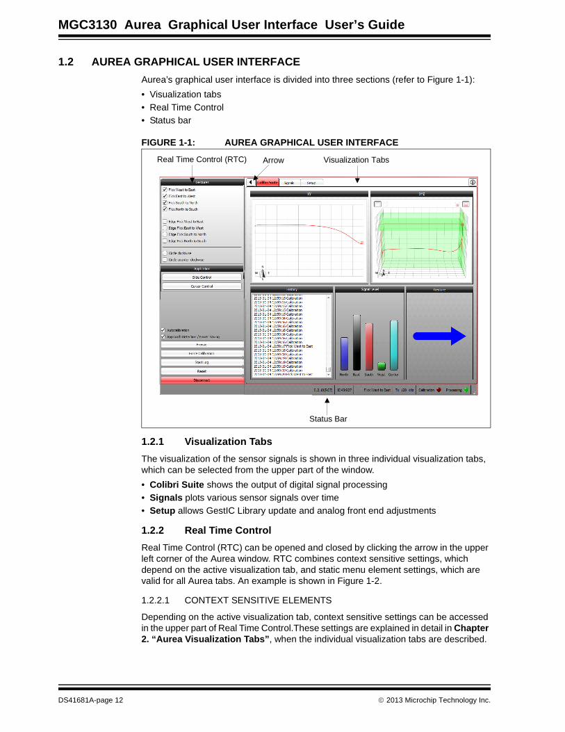
1.2 AUREA GRAPHICAL USER INTERFACE
Aurea’s graphical user interface is divided into three sections (refer to Figure 1-1):
• Visualization tabs
• Real Time Control
• Status bar
FIGURE 1-1: AUREA GRAPHICAL USER INTERFACE
1.2.1 Visualization Tabs
The visualization of the sensor signals is shown in three individual visualization tabs, which can be selected from the upper part of the window.
• Colibri Suite shows the output of digital signal processing
• Signals plots various sensor signals over time
• Setup allows GestIC Library update and analog front end adjustments
1.2.2 Real Time Control
Real Time Control (RTC) can be opened and closed by clicking the arrow in the upper left corner of the Aurea window. RTC combines context sensitive settings, which depend on the active visualization tab, and static menu element settings, which are valid for all Aurea tabs. An example is shown in Figure 1-2.
1.2.2.1 CONTEXT SENSITIVE ELEMENTS
Depending on the active visualization tab, context sensitive settings can be accessed in the upper part of Real Time Control.These settings are explained in detail in Chapter 2. “Aurea Visualization Tabs”, when the individual visualization tabs are described.
Visualization TabsReal Time Control (RTC)
Status Bar
Arrow
DS41681A-page 12 2013 Microchip Technology Inc.

Overview
1.2.2.2 STATIC MENU ELEMENTS
Major menu elements are always visible across all tabs and can be accessed in the lower left corner of the RTC screen. These static menu elements are:
• Start Log/Stop Log: Records and saves sensor data into a log file. Refer to Chapter 3. “Advanced Aurea Features” for additional details.
• Reset: Initiates a reset of the MGC3130.
• Connect/Disconnect: Toggles a connect and disconnect of the USB connection between the PC and the attached GestIC hardware.
FIGURE 1-2: AUREA REAL TIME CONTROL
Context Sensitive Menu Elements
Static Menu Elements
2013 Microchip Technology Inc. DS41681A-page 13

MGC3130 Aurea Graphical User Interface User’s Guide
1.2.3 Status Bar
The static status bar is located at the bottom of the Aurea window, and provides information about the recent status of the MGC3130 system (refer to Figure 1-3).
The following information displays from left to right:
• GestIC Library version read from the MGC3130 after startup and reset
• Colibri Suite version read from the MGC3130 after startup and reset
• Gesture indication shows the latest recognized gesture (only when the Colibri Suite tab is active)
• Tx working frequency currently used by the MGC3130
• Calibration indication flashes when a sensor calibration is issued
• Processing indication lights up when the MGC3130 is in processing mode, and turns off when in power-saving mode
FIGURE 1-3: AUREA STATUS BAR
Calibration Indication
Processing IndicationTx Working Frequency
Colibri Suite Version
GestIC Library Version
Gesture Indication
DS41681A-page 14 2013 Microchip Technology Inc.

MGC3130 AUREAGRAPHICAL USER INTERFACE
USER’S GUIDE
Chapter 2. Aurea Visualization Tabs
This chapter describes the individual visualization tabs of Aurea, and the respective context sensitive settings within Real Time Control.
2.1 COLIBRI SUITE
2.1.1 Colibri Suite Visualization Tab
The Colibri Suite tab displays the MGC3130 3D gesture recognition and position tracking features, and is divided into five sub-windows (Figure 2-1):
• XY position tracking plot (2D)
• XYZ position tracking plot (3D)
• Signal level bar graph
• History logging window
• Gesture indication window
FIGURE 2-1: COLIBRI SUITE VISUALIZATION TAB
Note: When the Approach Detection/Power Saving feature is enabled, the MGC3130 controller is set to sleep when no hand is present and the processing indication is turned off. In addition, the signal stream stops and the tab background turns grey. When a hand approaches the sensing area, the system will wake up.
XYZ plot (3D)XY plot (2D)
History logging Signal level bar graph Gesture indication
2013 Microchip Technology Inc. DS41681A-page 15
MGC3130 Aurea Graphical User Interface User’s Guide
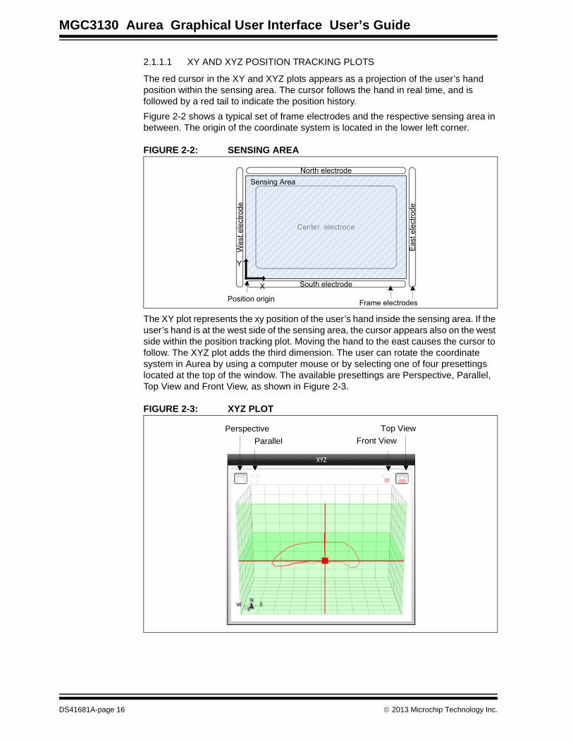
2.1.1.1 XY AND XYZ POSITION TRACKING PLOTS
The red cursor in the XY and XYZ plots appears as a projection of the user’s hand position within the sensing area. The cursor follows the hand in real time, and is followed by a red tail to indicate the position history.
Figure 2-2 shows a typical set of frame electrodes and the respective sensing area in between. The origin of the coordinate system is located in the lower left corner.
FIGURE 2-2: SENSING AREA
The XY plot represents the xy position of the user’s hand inside the sensing area. If the user’s hand is at the west side of the sensing area, the cursor appears also on the west side within the position tracking plot. Moving the hand to the east causes the cursor to follow. The XYZ plot adds the third dimension. The user can rotate the coordinate system in Aurea by using a computer mouse or by selecting one of four presettings located at the top of the window. The available presettings are Perspective, Parallel, Top View and Front View, as shown in Figure 2-3.
FIGURE 2-3: XYZ PLOT
Center electrode
North electrode
South electrode
Westelectrode
Eastelectrode
CCeeenntteerr eelleecccttrrooddee
Sensing Area
X
Y
Frame electrodesPosition origin
Perspective
Parallel
Top View
Front View
DS41681A-page 16 2013 Microchip Technology Inc.

Aurea Visualization Tabs
2.1.1.2 SIGNAL LEVEL
The sensor signals are displayed in the Signal Level bar graphic. To distinguish between the individual electrodes, they are color coded and labelled with cardinal directions (north, east, south, west, center). Approaching one electrode causes the respective signal to increase.
2.1.1.3 HISTORY LOGGING
The history logging window lists important events like calibrations and the classification of gestures. A complete log of messages and events is contained in the log file. Refer to Chapter 3. “Advanced Aurea Features” for additional details.
2.1.1.4 GESTURE INDICATION
The classification of gestures are displayed in the gesture indication window. Refer to Section 2.1.2 “Colibri Suite Real Time Control ” for guidance on performing gestures and controlling the available gesture set.
2.1.2 Colibri Suite Real Time Control
The Real Time Control of the Colibri Suite tab allows the control of gestures in the Gestures section, the launch of demo applications in the Applications section and the control of selected features applied to the MGC3130 (refer to Figure 2-4).
FIGURE 2-4: COLIBRI SUITE REAL TIME CONTROL
2.1.2.1 GESTURES
The Colibri Suite uses Hidden Markov Models (HMM) providing user-independent gesture recognition. The gesture recognition starts when a hand enters the sensing area, or when a movement is detected after a resting period. A gesture ends when a hand leaves the sensitive area or rests inside. The supported gestures can have various sizes and can be performed at various speeds, within limits. For instance, gesture recognition does not trigger when the movement of a gesture is very slow or particularly short.
Gestures
Applications
Features
2013 Microchip Technology Inc. DS41681A-page 17

MGC3130 Aurea Graphical User Interface User’s Guide
2.1.2.1.1 Flick Gestures
A flick gesture is defined as a linear hand or finger movement in a specified direction. Flick gestures can start and end inside and outside the sensing area.
The Colibri Suite supports flick gestures in four directions and can further distinguish edge flicks. Edge flicks are performed at the edge of the sensing area. They always start outside the sensing area and cover less than 70% of it.
The implementation of flick recognition is illustrated in Figure 2-5 on the example of flicks from west to east.
FIGURE 2-5: EXAMPLES FOR FLICK RECOGNITION
Colibri RTC supports the flick gestures listed in Table 2-1. The gestures can be individually enabled and disabled by checking and unchecking the respective checkboxes.
2.1.2.1.2 Circle Gestures
A circle gesture is defined as a hand or finger movement performing a full circle. Circle gestures must be performed solely inside the sensing area and should be circular in formation. To be classified as a gesture, the user must stop moving for a little while after one complete rotation or exit the sensing area. Constantly gesturing circles without interruption will not be recognized.
TABLE 2-1: FLICK GESTURES
Symbol Gesture Symbol Gesture
Flick West to East Edge Flick West to East
Flick East to West Edge Flick East to West
Flick South to North Edge Flick South to North
Flick North to South Edge Flick North to South
Sensing area
South electrode
Eastelectrode
North electrodeWestelectrode
Flick
Flick
Flick
Flick
Flick
70 %Edge Flick
Flick
DS41681A-page 18 2013 Microchip Technology Inc.

Aurea Visualization Tabs
Colibri RTC supports circle gestures as listed in Table 2-2. The gestures can be individually enabled and disabled by checking and unchecking the respective checkboxes.
2.1.2.2 APPLICATIONS
Two applications can be launched in RTC: Slide Show and Cursor Control.
2.1.2.2.1 Slide Show
Slide Show allows the user to control presentations only by using gestures. Three simple flick gestures are mapped to predefined keys emulating keystrokes (refer to Table 2-3).
For example, control Microsoft PowerPoint® with gestures as follows:
1. Click Slide Show in the Applications section.
2. Open a Microsoft PowerPoint presentation of your choice.
3. Perform flick gesture from south to north to start presentation.
4. Perform flick gesture from east to west to go to next slide.
5. Perform flick gesture from west to east to go to previous slide.
6. Deactivate Slide Show within Aurea to quit.
TABLE 2-2: CIRCLE GESTURES
Symbol Gesture
Circle clockwise
Circle counter-clockwise
Gesture Recognition Notes
Note 1: The gesture recognition software provides a garbage model to classify unintended gestures. These gestures can be identified as “garbage model” in the history logging window.
Note 2: Individual gestures can be enabled or disabled within RTC. Reducing the gesture set will increase the recognition rate.
Note 3: In the current alpha release, HMM gesture recognition is running within the Aurea application. Integration into the MGC3130 controller will be provided in a future version. Refer to the Aurea Release Notes.
TABLE 2-3: GESTURE SUPPORT IN SLIDE SHOW
Symbol Gesture Windows Key
Flick South to North F5
Flick East to West Right arrow
Flick West to East Left arrow
2013 Microchip Technology Inc. DS41681A-page 19

MGC3130 Aurea Graphical User Interface User’s Guide
2.1.2.2.2 Cursor Control
The Cursor Control application demonstrates the PC mouse cursor controlled by the MGC3130. Start the application and move the mouse cursor by sliding your hand over the sensing area of your GestIC device. Quit the application at any time by using the Escape key on your keyboard.
2.1.2.3 FEATURE CONTROL
2.1.2.3.1 Autocalibration Checkbox
For the electrode system to continuous adapt to environmental changes, the GestIC Library includes an auto calibration functionality. The calibration events can be watched in the status bar (refer to Section 1.2.3 “Status Bar ”) and the history logging window of the Colibri visualization tab. Uncheck the Autocalibration checkbox to disable the autocalibration feature.
2.1.2.3.2 Approach Detection / Power Saving Checkbox
Uncheck the Approach Detection/Power Saving checkbox to disable the Wake-up on Approach feature. This forces the system to continuously run in Processing mode.
2.1.2.3.3 Freeze
Press Freeze to freeze the visualization window. Press it again to continue plotting.
2.1.2.3.4 Force Calibration Button
Press Force Calibration to calibrate the sensor manually. Make sure the sensor is not influenced by the user when executing a calibration. The idle system is properly calibrated when the Signal Deviation of all channels is at or near zero.
Note 1: When Autocalibration is disabled, a system calibration can be started by the Force Calibration button.
Note 2: When Autocalibration is disabled, Approach Detection is also disabled.
DS41681A-page 20 2013 Microchip Technology Inc.

Aurea Visualization Tabs
2.2 SIGNALS
2.2.1 Signals Visualization Tab
The Signals tab plots the data streamed from the MGC3130 over time (refer to Figure 2-6). The unit of the signals is digits. On startup, Aurea plots Signal Deviation data. The user can select the following signals in RTC (refer to Section 2.2.2.7 “Signal Type Dropdown List”):
• Uncalibrated Signal
• Signal Deviation
• Signal Deviation Mean
• Noise Level
FIGURE 2-6: SIGNALS TAB WINDOW
Note: When the Approach Detection/Power Saving feature is enabled, the MGC3130 controller is set to sleep when no hand is present and the pro-cessing indication is turned off. In addition, the signal stream stops and the tab background turns grey. When a hand approaches the sensing area, the system will wake up.
2013 Microchip Technology Inc. DS41681A-page 21

MGC3130 Aurea Graphical User Interface User’s Guide
2.2.2 Signals Real Time Control
When Signals tab is active, Real Time Control allows the configuration of the plot in the Signals window, and the control of selected features applied to the MGC3130 (Figure 2-7).
FIGURE 2-7: SIGNALS REAL TIME CONTROL
The individual GUI elements are described next.
2.2.2.1 CHANNELS
The channels section allows the user to select the electrode signals plotted in the visualization tab. In the standard configuration, all five channels are displayed. For a detailed look into one electrode signal, unused channels can be unchecked.
2.2.2.2 LEVELS
The most recent signal values (time = 0) are shown in the Levels section. The values can be copied and pasted to an application of your choice (e. g. Microsoft Excel®). Before selecting the values, the signal stream must be frozen first.
2.2.2.3 AUTOCALIBRATION CHECKBOX
For the electrode system to continuous adapt to environmental changes, the GestIC Library includes an auto calibration functionality. The calibration events can be watched in the status bar (refer to Section 1.2.3 “Status Bar ”) and the history logging window of the Colibri visualization tab. Uncheck the Autocalibration checkbox to disable the autocalibration feature.
Signals
Features
Note 1: When Autocalibration is disabled, a system calibration can be started by the Force Calibration button.
Note 2: When Autocalibration is disabled, Approach Detection is also disabled.
DS41681A-page 22 2013 Microchip Technology Inc.

Aurea Visualization Tabs
2.2.2.4 APPROACH DETECTION / POWER SAVING CHECKBOX
Uncheck the Approach Detection/Power Saving checkbox to disable the Wake-up on Approach feature. This forces the system to continuously run in Processing mode.
2.2.2.5 LOCK ZOOM LEVEL CHECKBOX
Check the Lock Zoom Level checkbox to disable auto-scaling the y-axis in the Signals plot.
2.2.2.6 FREEZE
Press Freeze to freeze the visualization window. Press it again to continue plotting.
2.2.2.7 SIGNAL TYPE DROPDOWN LIST
A dropdown list allows selecting the signal streamed by the MGC3130. This signal is then displayed in the plot within the Signals tab. The provided signals are listed in Table 2-4.
2.2.2.8 AUTOMATIC FREQUENCY HOPPING DROPDOWN LIST
Depending on the external noise conditions, the MGC3130 controller chooses the best working frequency automatically. The automatic frequency hopping can be deactivated by selecting a working frequency from the dropdown list. The following frequencies are available: 73 kHz, 91 kHz, 105 kHz, 114 kHz and 128 kHz.
2.2.2.9 FORCE CALIBRATION BUTTON
Press Force Calibration to calibrate the sensor manually. Make sure the sensor is not influenced by the user when executing a calibration. The idle system is properly calibrated when the Signal Deviation of all channels is at or near zero.
TABLE 2-4: AUREA SIGNALS
Name of Signal Description
Uncalibrated Signal The Uncalibrated Signal is taken directly from the decimation filter implemented in the MGC3130. Any other signals are calculated from there. An additional clipping indication is displayed below the signal level window.
Signal Deviation Signal Deviation shows the signals received from the electrodes after preprocessing and calibration. When there is no approach by a hand, the signals are at or near zero. A users approach causes the signal deviation to rise.
Signal Deviation Mean The Signal Deviation Mean is the Signal Deviation with a simple moving average filter applied. The filtering is executed within Aurea with a filter length of 2048 samples (10 seconds). This signal is used when recording a sensitivity profile (refer to 3.2 “Sensitivity Profile Acquisition”). A pop up window is shown during the aver-aging time. It automatically disappears when data are valid.
Noise Level The Noise Level is defined as the Standard Deviation of the Uncali-brated Signal. It is calculated over 20480 samples (100 seconds) and gives information about the self noise level of the sensor sys-tem. A pop up window is shown during the averaging time. It auto-matically disappears when data are valid.
2013 Microchip Technology Inc. DS41681A-page 23

MGC3130 Aurea Graphical User Interface User’s Guide
2.3 SETUP
The setup visualization tab collects functions to adjust the hardware settings of the MGC3130 and to update the GestIC Library.
2.3.1 Setup Visualization Tab
When switching to the Setup tab, the Rx signal is shown. The signal plot is generated by sweeping the sampling time relative to the time instance when the Tx potential is switched to its high level. Colibri suite uses the level at the sampling point, indicated in Figure 2-8, to generate the Uncalibrated Signal for further processing. The Rx signal is generated at a working frequency of 128 kHz. The unit is digits.
The signal plot allows the user to evaluate the quality of the analog sensor signal. An optimal signal shows a low overshoot in the beginning and is settled at the sampling point. In addition, it should be close to 32,768 digits at the sampling point. The RTC provides parameters for signal optimization.
FIGURE 2-8: SETUP VISUALIZATION TAB
32768 digits
Sampling point
DS41681A-page 24 2013 Microchip Technology Inc.

Aurea Visualization Tabs
2.3.2 Setup Real Time Control
Real Time Control is divided in two sections – Analog front end settings and GestIC Library Update (Figure 2-9).
FIGURE 2-9: SIGNALS REAL TIME CONTROL
2.3.2.1 ANALOG FRONT END SETTINGS
The analog front end settings comprise of Signal Matching and Tx Settings. These settings can be modified by using the respective slider. For fine tuning, click on the slider and use the arrow keys on your PC keyboard.
The analog front end settings can be stored permanently into the MGC3130 controller Flash by clicking Store in Flash.
2.3.2.1.1 Signal Matching
Signal matching parameters are used to adjust the Rx signal level at the sampling point.
• Increase Signal Matching parameters to raise the signal
• Decrease Signal Matching parameters to lower the signal
• Press Autoparameterization to automatically signal match all electrodes exe-cuted by Aurea
2.3.2.1.2 Tx Settings
The Tx amplitude and slew rate can be modified within the Tx Settings section. By default, the Tx level is adjusted to the maximum amplitude and the slew rate to the fastest value. In case modifications are necessary, both settings can be adjusted using the respective slider.
Analog Front End Settings
GestIC Library Update
2013 Microchip Technology Inc. DS41681A-page 25

MGC3130 Aurea Graphical User Interface User’s Guide
2.3.2.2 GESTIC LIBRARY UPDATE
The GestIC Library can be easily updated as follows:
1. Press Open and Flash Library File.
2. Within the pop up window, select the library .enc-file from your local drive.
3. Click Open and the update starts automatically.
4. Wait a few seconds until the update is fully executed and the controller has performed a restart.
DS41681A-page 26 2013 Microchip Technology Inc.

MGC3130 AUREAGRAPHICAL USER INTERFACE
USER’S GUIDE
Chapter 3. Advanced Aurea Features
3.1 LOGGING SENSOR DATA
It is possible to log and store the data streamed from the MGC3130 controller to the PC. This can be used for observing data over long time periods and for system debugging. The log file contains:
• MESSAGE: All messages streamed by the MGC3130 in hex format
• DATA: Sensor Data decoded from the respective messages. The data fields contain position, uncalibrated sensor data, signal deviation and gestures
• STATUS: Status information from the Colibri Suite decoded from the respective messages. The data fields contain operation mode, working frequency, calibration and reset events
3.1.1 Record a Log File
To start logging data:
1. Press the Start Log button in the lower part of the Real Time Control section. Aurea immediately starts logging data in the background. The logged data include a 30 second history.
2. In the dialog box confirm the file name and press OK.
3. Press Stop Log to stop the logging process.
3.1.2 Log File Content and Format
The log file is a text file containing consecutive messages separated by line feeds. Individual data fields are tab separated. The kind of data being logged depends on the active visualization tab, and the content displayed inside. If there are data which are not logged, the respective data fields are kept empty. An example of the log file is shown in Figure 3-1.
Note: The kind of messages being logged depends on the active visualization tab, and the content displayed inside (refer also to Section 3.1.2 “Log File Content and Format ”).
2013 Microchip Technology Inc. DS41681A-page 27

MGC3130 Aurea Graphical User Interface User’s Guide
FIGURE 3-1: LOG FILE
Table 3-1 and 3-2 explain the data fields of the decoded messages.
TABLE 3-1: DATA
Data Field Description
Position Positions are logged any time the GestIC® Library detects a valid position. The data give the position of the user’s hand in the Cartesian coordi-nate system. Position data of [0,0,0] represent the origin of the coordi-nate system, and data of [65535, 65535, 65535] are the maximum dimension of the sensing area. For coordinate system orientation and origin, refer to Section 2.1.1 “Colibri Suite Visualization Tab”.Pos x: Range: (0..65535)Pos y: Range: (0..65535)Pos z: Range: (0..65535)
Uncalibrated Signal The Uncalibrated Signal (CIC) is logged when Uncalibrated Signal or Noise Level is selected in the Signals tab.CIC S (South): Range: (-3.402823e+38..3.402823e+38)CIC W (West): Range: (-3.402823e+38..3.402823e+38)CIC N (North): Range: (-3.402823e+38..3.402823e+38) CIC E (East): Range: (-3.402823e+38..3.402823e+38)CIC C (Center): Range: (-3.402823e+38..3.402823e+38)
Signal Deviation Signal Deviation (SD) is logged when Signal Deviation or Signal Devi-ation Mean is selected in the Signals tab or when Colibri Suite tab is active.SD S (South): Range: (-3.402823e+38..3.402823e+38)SD W (West): Range: (-3.402823e+38..3.402823e+38)SD N (North): Range: (-3.402823e+38..3.402823e+38) SD E (East): Range: (-3.402823e+38..3.402823e+38)SD C (Center): Range: (-3.402823e+38..3.402823e+38)
Gesture Gestures are logged any time a gesture is recognized.Gesture info is given in plain text.
DS41681A-page 28 2013 Microchip Technology Inc.

Advanced Aurea Features
3.2 SENSITIVITY PROFILE ACQUISITION
The sensitivity profile gives information about the system performance and, thus, is essential when benchmarking individual GestIC systems. It is defined as signal devia-tion measured over positions and acquired by moving a defined measuring object (“hand brick”) over the sensitive area from one side to the other. Preconditions
While recording sensitivity profiles, the MGC3130 controller must run in Processing mode with a fixed Tx working frequency of e.g. 105 kHz. Autocalibration must be deac-tivated. The following steps set up the GestIC system for sensitivity profile acquisition:
1. Connect the GestIC device to your PC via USB and open Aurea.exe.
2. Activate the Signals visualization tab and display Real Time Control by clicking on the upper left arrow.
3. Turn off Autocalibration in feature control. Deactivating Autocalibration also dis-ables the Approach Detection feature. The controller is constantly running in Pro-cessing mode.
4. Set Tx working frequency to 105 kHz.
5. Select the Signal Deviation Mean signals from the dropdown list in signal control.
You can now start recording the sensitivity profile.
3.2.1 Sensor Calibration
Use the Force Calibration button for manually calibrating the system when there is no approach to the system (measuring object is not within the sensing area).
TABLE 3-2: STATUS
Data Field Description
Running Indicates if DSP operating mode is running.Possible values: 1 = running0 = MGC is going into Self Wake-up mode
fTx Tx working frequency in kHzRange: (60..128)
Callnfo Calibration information in hex format.Possible values: Bit 1: forced calibrationBit 2: start-up calibrationBit 3: gesture-triggered calibrationBit 4: negative value calibrationBit 5: idle calibrationBit 6: invalidity calibrationBit 10: blocked calibrationRange: (0..65535) resp. (b0000 0000 00000 0000..b1111 1111 1111 1111)
Reset Reset is indicated when a reset of MGC3130 was successful.
2013 Microchip Technology Inc. DS41681A-page 29

MGC3130 Aurea Graphical User Interface User’s Guide
3.2.2 Measurement
1. Place the brick in the defined start position (e.g., “hand brick” at 3 cm high over the center of the east electrode).
2. Read the Signal Deviation values and move the brick to the next position (e.g., 1 cm toward west).
3. Continue until the brick is at the end position (west electrode). In order to record data at each of the above steps, press Freeze to halt the signal stream. Transfer the Signal Deviation Mean values to another application by marking and copying them through the clipboard (refer to Figure 3-2).
FIGURE 3-2: TRANSFER SIGNAL VALUES
Note: Due to the applied filter, the Signal Deviation Mean signals show a delay of 10 seconds. Make sure the signals are settled before using them.
DS41681A-page 30 2013 Microchip Technology Inc.

MGC3130 AUREAGRAPHICAL USER INTERFACE
USER’S GUIDE
Appendix A. Glossary
TABLE A-1: GLOSSARY
Term Definition
AFE Analog front end
Application Host PC or embedded controller which controls the MGC3130
Aurea Visualization and Control Software
MGC3130 control software
Colibri Suite Embedded DSP suite within the GestIC® Library
Deep Sleep Power-saving mode of the MGC3130
E-field Electrical field
Frame Electrodes Rectangular set of 4 electrodes for E-field sensing
GestIC TechnologyTechnology providing 3D free-space gesture recognition utilizing the principles of electrical near-field sensing
GestIC LibraryMicrochip GestIC Library includes the implementation of MGC3130 features and is delivered as an encrypted binary preprogrammed on the chip’s Flash memory
Gesture Recognition GestIC technology feature: “.. based on HMM classifier”
Gesture Set HMM gestures
Hand Brick Copper coated test block (7 cm x 4 cm x 4 cm)
HMM Hidden Markov Model
MGC3130 Single Zone 3D Gesture Sensing Controller
Position Tracking GestIC technology feature
Sabrewing MGC3130 evaluation board
Self Wake-Up MGC3130 Power-Saving mode
Sensing ZoneThe three dimensional area near the electrodes in which tracking/gesture recognition can be performed
Signal Deviation Term for the delta of the sensor signal on approach of the hand (“Signalhub”)
Spacer Brick Spacer between the sensor layer and hand brick(styrofoam block 4 cm x 4 cm x h with h= 1 / 2 / 3 / 5 / 8 / 12 cm)
SPU Signal Processing Unit
Wake-Up on ApproachGestIC technology feature: Power-Saving mode of the MGC3130 with approach detection
2013 Microchip Technology Inc. DS41681A-page 31

DS41681A-page 32 2013 Microchip Technology Inc.
AMERICASCorporate Office2355 West Chandler Blvd.Chandler, AZ 85224-6199Tel: 480-792-7200 Fax: 480-792-7277Technical Support: http://www.microchip.com/supportWeb Address: www.microchip.com
AtlantaDuluth, GA Tel: 678-957-9614 Fax: 678-957-1455
BostonWestborough, MA Tel: 774-760-0087 Fax: 774-760-0088
ChicagoItasca, IL Tel: 630-285-0071 Fax: 630-285-0075
ClevelandIndependence, OH Tel: 216-447-0464 Fax: 216-447-0643
DallasAddison, TX Tel: 972-818-7423 Fax: 972-818-2924
DetroitFarmington Hills, MI Tel: 248-538-2250Fax: 248-538-2260
IndianapolisNoblesville, IN Tel: 317-773-8323Fax: 317-773-5453
Los AngelesMission Viejo, CA Tel: 949-462-9523 Fax: 949-462-9608
Santa ClaraSanta Clara, CA Tel: 408-961-6444Fax: 408-961-6445
TorontoMississauga, Ontario, CanadaTel: 905-673-0699 Fax: 905-673-6509
ASIA/PACIFICAsia Pacific OfficeSuites 3707-14, 37th FloorTower 6, The GatewayHarbour City, KowloonHong KongTel: 852-2401-1200Fax: 852-2401-3431
Australia - SydneyTel: 61-2-9868-6733Fax: 61-2-9868-6755
China - BeijingTel: 86-10-8569-7000 Fax: 86-10-8528-2104
China - ChengduTel: 86-28-8665-5511Fax: 86-28-8665-7889
China - ChongqingTel: 86-23-8980-9588Fax: 86-23-8980-9500
China - HangzhouTel: 86-571-2819-3187 Fax: 86-571-2819-3189
China - Hong Kong SARTel: 852-2943-5100 Fax: 852-2401-3431
China - NanjingTel: 86-25-8473-2460Fax: 86-25-8473-2470
China - QingdaoTel: 86-532-8502-7355Fax: 86-532-8502-7205
China - ShanghaiTel: 86-21-5407-5533 Fax: 86-21-5407-5066
China - ShenyangTel: 86-24-2334-2829Fax: 86-24-2334-2393
China - ShenzhenTel: 86-755-8864-2200 Fax: 86-755-8203-1760
China - WuhanTel: 86-27-5980-5300Fax: 86-27-5980-5118
China - XianTel: 86-29-8833-7252Fax: 86-29-8833-7256
China - XiamenTel: 86-592-2388138 Fax: 86-592-2388130
China - ZhuhaiTel: 86-756-3210040 Fax: 86-756-3210049
ASIA/PACIFICIndia - BangaloreTel: 91-80-3090-4444 Fax: 91-80-3090-4123
India - New DelhiTel: 91-11-4160-8631Fax: 91-11-4160-8632
India - PuneTel: 91-20-2566-1512Fax: 91-20-2566-1513
Japan - OsakaTel: 81-6-6152-7160 Fax: 81-6-6152-9310
Japan - TokyoTel: 81-3-6880- 3770 Fax: 81-3-6880-3771
Korea - DaeguTel: 82-53-744-4301Fax: 82-53-744-4302
Korea - SeoulTel: 82-2-554-7200Fax: 82-2-558-5932 or 82-2-558-5934
Malaysia - Kuala LumpurTel: 60-3-6201-9857Fax: 60-3-6201-9859
Malaysia - PenangTel: 60-4-227-8870Fax: 60-4-227-4068
Philippines - ManilaTel: 63-2-634-9065Fax: 63-2-634-9069
SingaporeTel: 65-6334-8870Fax: 65-6334-8850
Taiwan - Hsin ChuTel: 886-3-5778-366Fax: 886-3-5770-955
Taiwan - KaohsiungTel: 886-7-213-7828Fax: 886-7-330-9305
Taiwan - TaipeiTel: 886-2-2508-8600 Fax: 886-2-2508-0102
Thailand - BangkokTel: 66-2-694-1351Fax: 66-2-694-1350
EUROPEAustria - WelsTel: 43-7242-2244-39Fax: 43-7242-2244-393Denmark - CopenhagenTel: 45-4450-2828 Fax: 45-4485-2829
France - ParisTel: 33-1-69-53-63-20 Fax: 33-1-69-30-90-79
Germany - MunichTel: 49-89-627-144-0 Fax: 49-89-627-144-44
Italy - Milan Tel: 39-0331-742611 Fax: 39-0331-466781
Netherlands - DrunenTel: 31-416-690399 Fax: 31-416-690340
Spain - MadridTel: 34-91-708-08-90Fax: 34-91-708-08-91
UK - WokinghamTel: 44-118-921-5869Fax: 44-118-921-5820
Worldwide Sales and Service
11/29/12