Embed Size (px)
Citation preview
MICROCONTROLLER BASED CONTACTLESS TACHOMETER
Project Members:-Hitesh PrateekJayant TiwariNavyug Tyagi
Under the guidance of:-Mrs S.V.Doke
PROJECT DESCRIPTION
Aim of the design is to develop a system based on Embedded microcontroller(8051) which is used as a digital contactless tachometer for measuring the speed(in rpm) of the AC(or) DC motor by using Infrared Frequency without the help of a expensive tachometer available in the market.

INTRODUCTION
• Tachometer is used for measuring rotation speed • It can be used to measure speed of a rotating
shaft• It can also be used to measure flow of liquid by
attaching a wheel with inclined vanes
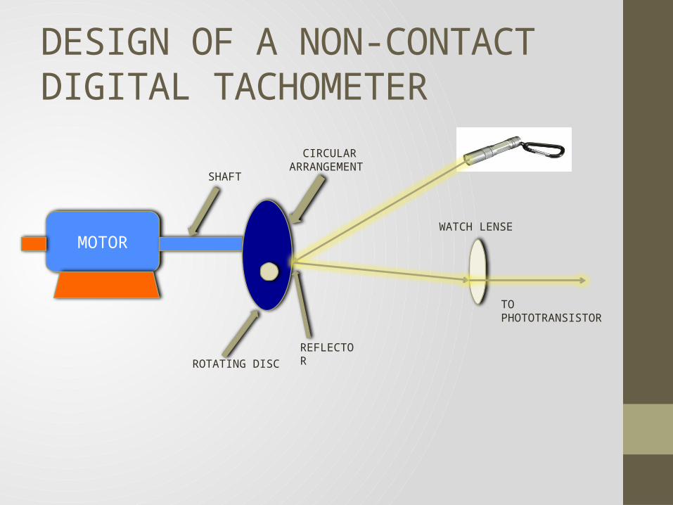
DESIGN OF A NON-CONTACT DIGITAL TACHOMETER
MOTOR
CIRCULAR ARRANGEMENT
SHAFT
ROTATING DISCREFLECTOR
WATCH LENSE
TO PHOTOTRANSISTOR
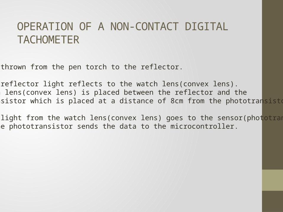
OPERATION OF A NON-CONTACT DIGITAL TACHOMETER
• Light is thrown from the pen torch to the reflector.
• From the reflector light reflects to the watch lens(convex lens).The watch lens(convex lens) is placed between the reflector and thephototransistor which is placed at a distance of 8cm from the phototransistor.
• Then the light from the watch lens(convex lens) goes to the sensor(phototransistor).And so the phototransistor sends the data to the microcontroller.
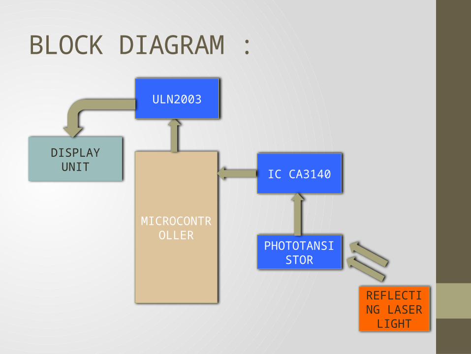
BLOCK DIAGRAM :
DISPLAY UNIT
MICROCONTROLLER
IC CA3140
PHOTOTANSISTOR
REFLECTING LASER LIGHT
ULN2003
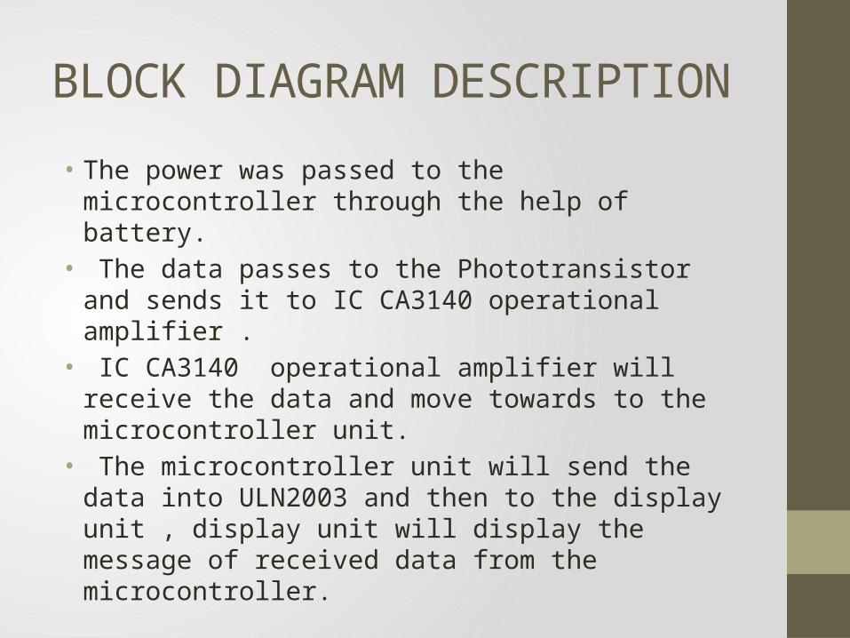
BLOCK DIAGRAM DESCRIPTION
• The power was passed to the microcontroller through the help of battery.
• The data passes to the Phototransistor and sends it to IC CA3140 operational amplifier .
• IC CA3140 operational amplifier will receive the data and move towards to the microcontroller unit.
• The microcontroller unit will send the data into ULN2003 and then to the display unit , display unit will display the message of received data from the microcontroller.
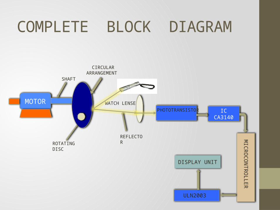
COMPLETE BLOCK DIAGRAM
MOTOR
CIRCULAR ARRANGEMENT
SHAFT
ROTATING DISCREFLECTOR
WATCH LENSE
IC CA3140
MICRO
CON
TROLLER
PHOTOTRANSISTOR
DISPLAY UNIT
ULN2003

PHOTOTRANSISTOR
PHOTOTRANSISTOR DESCRIPTION • A phototransistor is a type of photodetector capable of
converting light into either current or voltage, depending upon the mode of operation.
• The most-common variant is an NPN bipolar transistor with an exposed base region
• Here, light striking the base replaces what would ordinarily be voltage applied to the base -- so, a phototransistor amplifies variations in the light striking it.
• Note that phototransistors may or may not have a base lead (if they do, the base lead allows you to bias the phototransistor's light response.

7 SEGMENT DISPLAY
DESCRIPTION
• A seven-segment display (SSD), or seven-segment indicator, is a form ofelectronic display device for displaying decimal numerals that is analternative to the more complex dot-matrix displays.
• Seven-segment displays are widely used in digital clocks, electronic meters, and other electronic devices for displaying numerical information.

IC (INTEGRATED CIRCUIT)
CA 3140 OPERATIONAL AMPLIFIER ATMEL AT8920C51 MICROCONTROLLER
ULN2003 CURRENT BUFFER
IC’S DESCRIPTIONMICROCONTROLLER :- A microcontroller (sometimes abbreviated µC, uC or MCU) is a small computer on small computer on a single integrated circuit containing a processor core, memory, and programmable input/output peripherals. Program memory in the form of and programmable input/output peripherals . Program memory in the form of NOR flash or OTP ROM is also often included on chip, as well as a typically small amount of RAM. small amount of
OPERATIONAL AMPLIFIER :- An operational amplifier ("op-amp") is a DC -coupled high-gain electronic voltage amplifier with a differential input and, usually, a single-ended op-amp produces an output voltage that is typically hundreds of thousand times larger than the voltage difference between its input terminals. CURRENT BUFFER :-
Typically a current buffer amplifier is used to transfer a current from a first circuit, having a low output impedance level, to a second circuit with a high input impedance level. The interposed buffer amplifier prevents the second circuit from loading the first circuit unacceptably and interfering with its desired operation. In the ideal current buffer in the diagram, the input impedance is zero and the output impedance is infinite (impedance of an ideal current source is infinite). Again, other properties of the ideal buffer are: perfect linearity, regardless of signal amplitudes; and instant output response, regardless of the speed of the input signal.
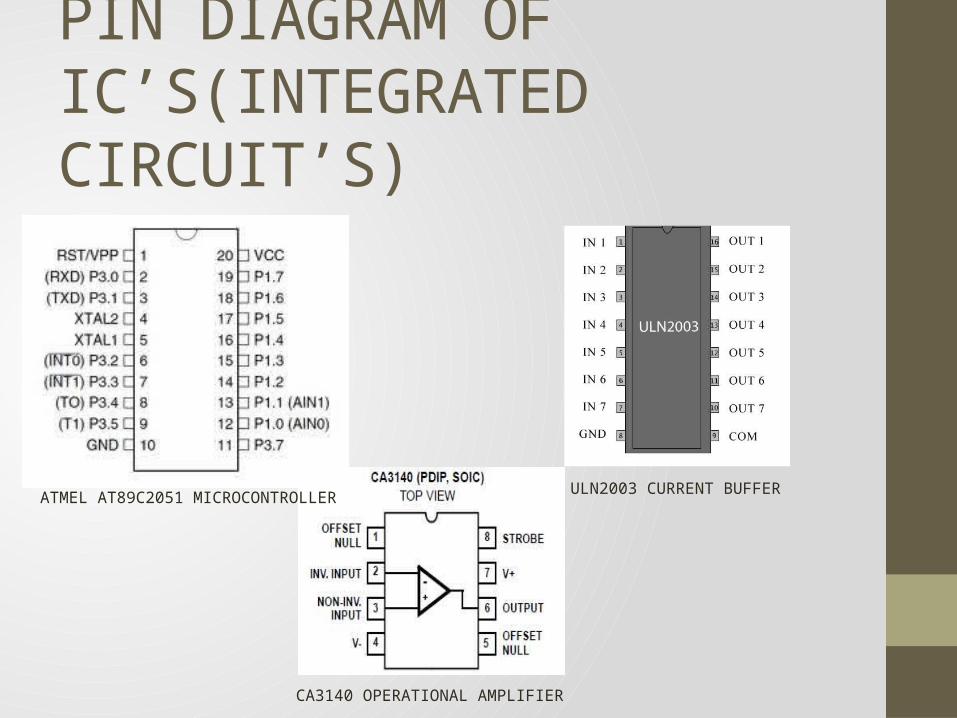
PIN DIAGRAM OF IC’S(INTEGRATED CIRCUIT’S)
ATMEL AT89C2051 MICROCONTROLLER ULN2003 CURRENT BUFFER
CA3140 OPERATIONAL AMPLIFIER
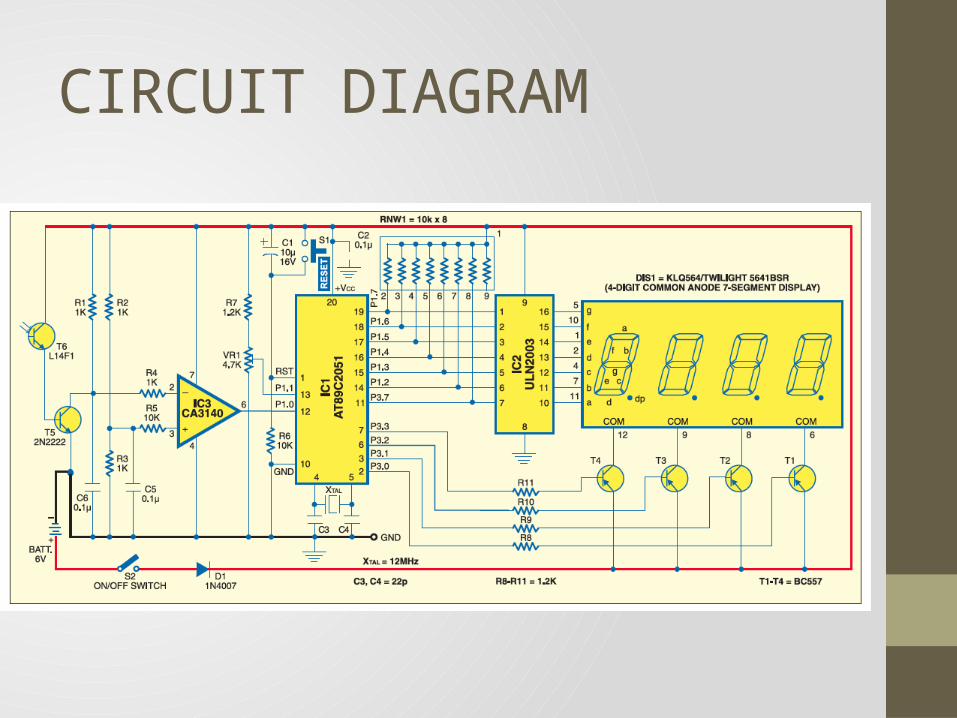
CIRCUIT DIAGRAM
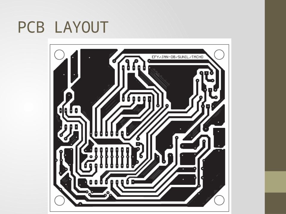
PCB LAYOUT
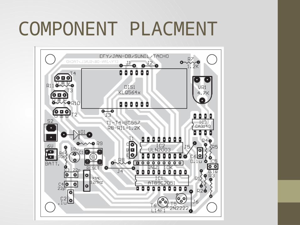
COMPONENT PLACMENT

THANK YOU


![Hetrogenious and lane less traffic controller using rfid [recovered]](https://img.pdfslide.net/doc/110x75/55812893d8b42a68488b46f9/hetrogenious-and-lane-less-traffic-controller-using-rfid-recovered.jpg)