Embed Size (px)
Citation preview
A CTA TECHNICA CORVINIENSIS – Bulletin of Engineering Tome XI [2018] | Fascicule 3 [July – September]
47 | F a s c i c u l e 3
1.Alok MUKHERJEE, 2.Susanta RAY, 3.Arabinda DAS
MICROCONTROLLER BASED SPEED CONTROL AND SPEED REGULATION SCHEME FOR BLDC MOTOR UNDER VARIABLE LOADING CONDITIONS 1-3. Department of Electrical Engineering, Jadavpur University, Kolkata, INDIA Abstract: Brushless dc (BLDC) motors are gaining immense popularity in recent era due to its major advantages over the more conventional motors, only put behind due to the cost involved in designing its most imperative controller. Hence, the design of a low cost, yet efficient and effective controller is an imperative part of the motor drive system. This paper presents a design and implementation of a microcontroller based low cost drive for a 3-phase, trapezoidal back-emf, permanent magnet BLDC motor. A Pulse Width Modulation (PWM) based modified adaptive two and half step digital on-off control algorithm has been designed to provide a constant operating speed overcoming the effect of variation in load with high load torque, as well as provide faster response during transients to restore speed. Proteus VSM (Virtual System Modeling) software is used as a real-time simulation tool to model the BLDC motor drive. Experimental verification has also been carried out to validate the simulated circuit. Keywords: BLDC motor, PIC18F4331 microcontroller, Proteus VSM software, Pulse Width Modulation (PWM) INTRODUCTION As the recent trend goes Brushless Direct Current (BLDC) motor have achieved huge popularity in recent era due to some remarkable advantages like high efficiency, high torque capability, lesser maintenance etc. over several conventional motors readily available in market. For its ease in control due t the electronic commutation and drive system and lesser maintenance due to the absence of brush-commutator arrangement, hence a higher efficiency, BLDC motor is replacing many conventional motor drives these days, especially in sophisticated drive applications where efficiency and performance plays the major role over its costing. Presence of strong permanent magnet rotor provides it with high power density enabling for high torque supply. The only drawback behind its most popularity as yet is its most essential but high cost controller responsible for the electronic commutation technique [1]-[6]. Microcontroller based embedded drive system, on the other side, are hugely popular these days for designing low cost, yet very much effective and robust controllers for several reasons including wide adaptability to modern control techniques, especially for systems with variable load applications with high torque demand, simultaneously requiring low speed regulation and of course, providing more flexibility of design etc. [7]-[9]. The proposed work deals with designing of such type of an algorithm using PIC18F4331 microcontroller and hardware implementation of the same. Proteus VSM simulation software is used for the purpose as a primary simulation platform. This allows microcontroller programs to be implemented directly to the simulation block, and later in practical microcontroller unit through any suitable programmer, allowing for lesser hardware development time and effort.
Real time change of input data is another advantage of the software making it closer to practical design [10]. In this work, an attempt has been made for designing a low cost variable load constant speed microcontroller based drive for a three phase trapezoidal back-emf permanent magnet BLDC motor. An 8 bit PIC18F4331 microcontroller has been chosen here due to a certain number of driver application modules like High-Speed Motion Feedback Module, 14-bit Power Control PWM Module, interrupt on bit change and 200 Ksps 10-bit A/D Converter modules etc. [7], [8], [11]. The drive scheme along with the BLDC motor has been initially designed in Proteus VSM simulation software [10]. A modified adaptive on-off control scheme has been proposed here for variable load constant speed applications. Pulse Width Modulation (PWM) technique has been adopted here for developing a modified adaptive digital on-off control algorithm with 120-degree six-step commutation. Motor operation is restricted primarily between two discrete levels, operating between which the motor rotates with an average operating speed. An additional wider speed band is also incorporated in order to achieve faster response in restoration of speed about the reference speed in case of sudden and massive load change causing lesser overshoot. The algorithm is designed to overcome the effect of variation in load and rotate at a constant speed ensuring a good (low) speed regulation with high torque supply. A simulation based study of the proposed controller has been first carried out in software. A prototype has been designed and implemented in laboratory to validate the control scheme. BLDC MOTOR DRIVE DESIGN The block diagram of the close loop control scheme is presented in Figure 1. BLDC motor is the controlled block of the drive scheme. In our work, it is a four pole, star type, trapezoidal back-emf 3-phase BLDC motor. Three electrically equally (120o apart) spaced Hall sensors located over the
A CTA TECHNICA CORVINIENSIS – Bulletin of Engineering Tome XI [2018] | Fascicule 3 [July – September]
48 | F a s c i c u l e 3
three stator phases provide this information to the controller. The tacho-generator voltage output is scaled in compatibility with the microcontroller inbuilt 10-bit high speed ADC hardware module. PIC18F4331 microcontroller has been used as the basic control block which performs the following two basic purposes: — Maintaining the switching sequence of the six PWM
channels in synchronism with the Hall position signals to perform phase commutation.
— Adjust the PWM duty ratio to control the input voltage to the motor in synchronism with the speed feedback signal.
IRFZ44N n-channel MOSFET has been chosen here primarily for its high switching frequency, thus causing lesser switching loss yielding higher efficiency of the drive, high current carrying capability for designing high power drives and low gate drive current requirements. MOSFET driver has been used here primarily to pull up the microcontroller generated PWM logic “High” signal of +5V to +12 to +20V for the successful turn on of the MOSFETs, as well as for the electrical isolation between the control and power circuit. IC IR2101 has been used to design the motor drive for advantages. Besides, an inner current loop is also implemented to estimate the equivalent load as well as to limit load current within the rated value governed by the motor.
Figure 1. Schematic diagram
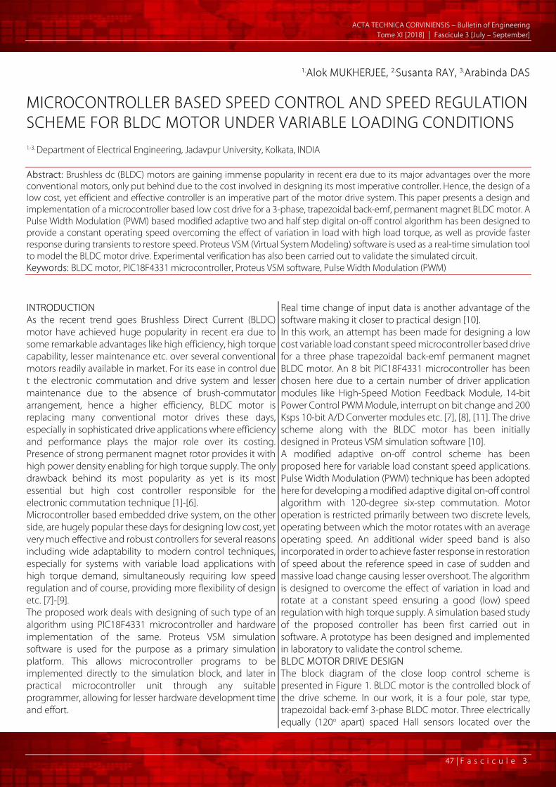
of the proposed BLDC motor drive SPEED CONTROL OF BLDC MOTOR AND CALIBRATION OF SOFTWARE MOTOR MODEL — Simple Voltage Control Method: The Speed Torque Characteristics of an ideal BLDC Motor is shown in Figure2. The Speed Torque Characteristics is drooping in nature providing a high torque at starting. Point C denotes the point of intersection of any load torque TL with the electromagnetic torque line AB. Thus for a specific load TL, C becomes the stable operating point. Knowledge of the motor speed-torque characteristics enables its easier mathematical modeling, and hence easier design of the constant speed drive under variable loading conditions. Easy speed control is possible due to the almost linear speed voltage characteristics as shown. The simple PWM voltage control scheme is described by:
Output Voltage (Vo) = Duty Ratio (D) × Input Voltage (Vin) Which shows the linear speed control can be achieved by the
simple control of duty ratio which is controlled only by entering proper duty ratios in the duty cycle registers of each channel; thus implementing a simple linear voltage control of BLDC motor [13].
Figure 2. Speed-torque characteristic of BLDC motor
— Calibration of Motor model in Proteus Software and Implementation of Voltage Control Method:
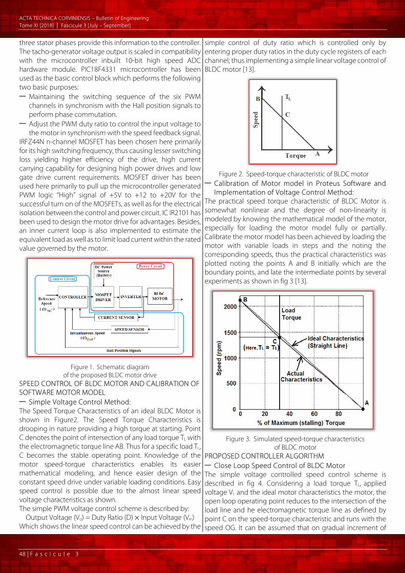
The practical speed torque characteristic of BLDC Motor is somewhat nonlinear and the degree of non-linearity is modeled by knowing the mathematical model of the motor, especially for loading the motor model fully or partially. Calibrate the motor model has been achieved by loading the motor with variable loads in steps and the noting the corresponding speeds, thus the practical characteristics was plotted noting the points A and B initially which are the boundary points, and late the intermediate points by several experiments as shown in fig 3 [13].
Figure 3. Simulated speed-torque characteristics
of BLDC motor PROPOSED CONTROLLER ALGORITHM — Close Loop Speed Control of BLDC Motor The simple voltage controlled speed control scheme is described in fig 4. Considering a load torque TL, applied voltage V1 and the ideal motor characteristics the motor, the open loop operating point reduces to the intersection of the load line and he electromagnetic torque line as defined by point C on the speed-torque characteristic and runs with the speed OG. It can be assumed that on gradual increment of
A CTA TECHNICA CORVINIENSIS – Bulletin of Engineering Tome XI [2018] | Fascicule 3 [July – September]
49 | F a s c i c u l e 3
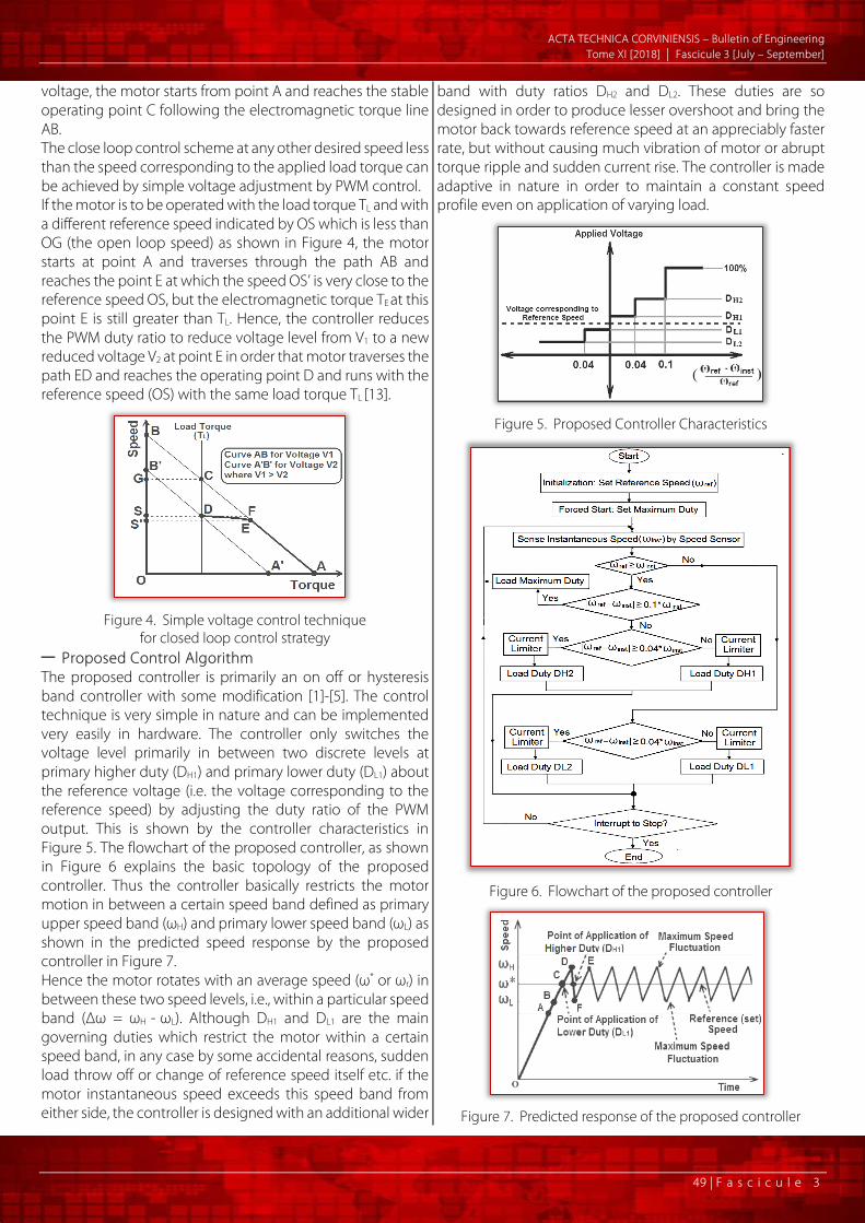
voltage, the motor starts from point A and reaches the stable operating point C following the electromagnetic torque line AB. The close loop control scheme at any other desired speed less than the speed corresponding to the applied load torque can be achieved by simple voltage adjustment by PWM control. If the motor is to be operated with the load torque TL and with a different reference speed indicated by OS which is less than OG (the open loop speed) as shown in Figure 4, the motor starts at point A and traverses through the path AB and reaches the point E at which the speed OS’ is very close to the reference speed OS, but the electromagnetic torque TE at this point E is still greater than TL. Hence, the controller reduces the PWM duty ratio to reduce voltage level from V1 to a new reduced voltage V2 at point E in order that motor traverses the path ED and reaches the operating point D and runs with the reference speed (OS) with the same load torque TL [13].
Figure 4. Simple voltage control technique
for closed loop control strategy — Proposed Control Algorithm The proposed controller is primarily an on off or hysteresis band controller with some modification [1]-[5]. The control technique is very simple in nature and can be implemented very easily in hardware. The controller only switches the voltage level primarily in between two discrete levels at primary higher duty (DH1) and primary lower duty (DL1) about the reference voltage (i.e. the voltage corresponding to the reference speed) by adjusting the duty ratio of the PWM output. This is shown by the controller characteristics in Figure 5. The flowchart of the proposed controller, as shown in Figure 6 explains the basic topology of the proposed controller. Thus the controller basically restricts the motor motion in between a certain speed band defined as primary upper speed band (ωH) and primary lower speed band (ωL) as shown in the predicted speed response by the proposed controller in Figure 7. Hence the motor rotates with an average speed (ω* or ωr) in between these two speed levels, i.e., within a particular speed band (Δω = ωH - ωL). Although DH1 and DL1 are the main governing duties which restrict the motor within a certain speed band, in any case by some accidental reasons, sudden load throw off or change of reference speed itself etc. if the motor instantaneous speed exceeds this speed band from either side, the controller is designed with an additional wider
band with duty ratios DH2 and DL2. These duties are so designed in order to produce lesser overshoot and bring the motor back towards reference speed at an appreciably faster rate, but without causing much vibration of motor or abrupt torque ripple and sudden current rise. The controller is made adaptive in nature in order to maintain a constant speed profile even on application of varying load.
Figure 5. Proposed Controller Characteristics
Figure 6. Flowchart of the proposed controller
Figure 7. Predicted response of the proposed controller

A CTA TECHNICA CORVINIENSIS – Bulletin of Engineering Tome XI [2018] | Fascicule 3 [July – September]
50 | F a s c i c u l e 3
The motor is forcefully started at first (point O) depending on the initial rotor position in any direction with full voltage applied (100% duty) when it starts rotating and the Hall signals starts changing its bit pattern. On any bit change of any one of the three Hall signals, the program sequence enters the interrupt subroutine where the duty ratio is adjusted properly by the proposed control algorithm. In each loop, the actual speed (ADC instantaneous value) is measured and compared with the reference speed (ADC set value) and the error is defined as follows:
Speed Error (ADC Error) = Speed Set (ADC reference value) - Actual Speed (ADC instantaneous value)
When error is positive and very large (say more than the wider tolerance limit) indicating that the motor instantaneous speed (ωinst) is far away from the reference speed (ωr), the controller assigns the maximum duty (100%), i,e., full voltage is applied in order to achieve highest acceleration, restrained only by the motor inertia and the load connected to the shaft. Thus rise time reduces considerably. When ωinst reaches the wider lower speed band at point A (say 10% lesser than the reference rpm), the controller reduces the duty ratio to DH2. The purpose of keeping this additional lower band is to slow down the motor in advance, even before crossing ωr, thus preparing for a reduced overshoot beforehand and yielding a better transient response, although sacrificing for a slightly higher rise time. The above two steps optimize between faster response during starting (i.e. providing faster acceleration) and lesser overshoot near reference speed. Even on application of this reduced voltage, the motor accelerates and enters the lower speed band at point B when error is still positive but say less than 4% of ωr, i.e., the ωinst is in between 96% to 100% of ωr, the controller imposes a further lower duty DH1 (which is slightly higher than the reference voltage corresponding to ωr) to reduce acceleration faster near the reference speed. These duty ratios are governed by the following factors: — Part contribution depending on the reference speed; — Part contribution depending on load connected, i.e., in
effect, depending on the current drawn from supply which is sensed by the installed DC link current sensor to estimate the load connected;
— An additional fixed part (depending on motor mechanical inertia) which is added (or subtracted) from the reference duty ratio to allow for hysteresis band control; and
— A very much negligible part contribution depending on the nonlinearity of speed - torque characteristics.
Even after decelerating, if the motor ωinst goes beyond ωr (at point C) due to its inertia and the applied voltage (overshoot region), i.e., if the error becomes just negative (i.e., say less than 4% of ωr), the controller loads a further lower value of duty DL1 (marginally lower than the reference voltage corresponding to ωr) to bring down ωinst below reference.
Now the motor decelerates toward reference performing maximum overshoot upto point D. In case of any accidental reasons or others, if the motor still overshoots and the error crosses the 4% band and enters say, 4-10% band (with negative error, beyond point D), a further lower duty DL2 is imposed for faster deceleration of the motor towards ωr . In any case, the motor slows down and crosses the reference speed from upper side this time at E and enters the lower band where higher duty DH1 is imposed again to produce acceleration. But similarly due to its inherent rotor inertia, the deceleration continues upto say point F where it starts to accelerate aging. All these duties are selected governing the same criteria as discussed previously. The combined effect of the rotor inertia and the applied voltage is explained mathematically in the following section. CONTROLLER DESIGN The mathematical model of the controller can be explained in steps as follows. Starting from the very fundamental motor equation, we derived the value of duty ratio (D) for the upper and lower levels, which are of the most importance in designing the proposed controller. The basic motor equations of the motor are given as:
IREVC += (1)
R)EV(I C −= (2)
where: » VC - controlled voltage; » E - motor back emf; » I - motor current; » R - motor armature resistance.
The motor back emf and the PWM controlled output voltage can be written as:
ω= EKE (3)
SC DVV = (4) Thus the motor current equations become as:
R)KDV(
I ES ω−= (5)
where: » KE - back emf constant; » ω - speed of motor in rad/sec; » VS - supply voltage
Since BLDC motor has permanent magnets in its poles, hence flux can be assumed as constant for further analysis. Hence, the electromagnetic torque produced by the motor can be assumed as directly proportional to the current as:
IKT TE = (6) where:
» TE - electromagnetic torque produced by the motor; » KT - torque constant;
Thus putting the value of motor current from (5) into (6) yields (7) as follows:
ω−=RKKD
RVK
T ETSTE
(7)
A CTA TECHNICA CORVINIENSIS – Bulletin of Engineering Tome XI [2018] | Fascicule 3 [July – September]
51 | F a s c i c u l e 3
Thus, it can be inferred from the above equation that the input voltage produces some toque at some speed depending on the motor constants, both electrical as well as mechanical. But the most important part that needs to be considered is the mechanical transient equation, based on which, all further modeling has been adopted to define the controller characteristics. Transient torque equations can be obtained for the motor from the mechanical side as:
LE TBdtdJT +ω+ω
= (8)
LT TBdtdJIK +ω+ω
= (9)
where: » J - polar moment of inertia the motor; » B - viscous friction coefficient; » TL - load torque;
— Steady State Analysis Before going to the transient analysis straight way, steady state operating point must be examined first for building the control logic in a simple way. It is defined at a point where the motor speed settles to almost a fixed value, i.e., the rate of change of speed becomes almost zero. Open loop stated state condition is achieved by applying a voltage on the motor and letting the motor to settle to a fixed speed depending on the load and mechanical parameters. This steady state speed (ωSS) and current (ISS) is obtained from (9) as follows: Since at steady state 0
dtd
=ω , thus putting this value in the
mechanical transient equation (9) yields:
BT
BIK LSST
SS −=ω (10)
LT
SST
SS TK1
KBI +ω= (11)
The above equation states that the amount of current taken by the motor is partly utilized in driving the load and the other part produces steady state motion depending on the rotor mechanical parameters. Thus equating the electromagnetic torque obtained from the electrical and mechanical equations, i.e., clubbing (7) and (8) gives:
ω−=+ω+ω
RKK
DRVK
TBdtdJ ETST
L (12)
The steady state condition of the above equation can be obtained by considering the same constraints as before:
SSET
SSST
LSS rKKD
rVK
TB ω−=+ω (13)
The steady state speed and the corresponding duty ratio can be obtained from (13) as follows:
L
ET
TSS
ET
SSS T
KKBR
KR
DK
KBR
V
+−
+=ω
(14)
LTS
SSETS
SS TKVRK
KBR
V1D
+ω
+= (15)
LSSSS TD β+αω= (15a) where:
» α =
+ E
TS
KKBR
V1 ;
» β =
TSKVR .
— Transient State Analysis Equation (15) is vitally important in determining primary higher duty (DH1) and primary lower duty (DL1). It is apparent from above that PWM duty ratio (D) must be set at a certain value DSS depending on ωSS and the load TL on the motor, governed by the motor parameters. In other words, the steady state duty ratio, for steady state speed, must comprise of two parts: — one (αωSS) depending on the open loop steady state
speed, — other (βTL) depending on load; α and β being constants, only depending on the motor electrical and mechanical parameters. Thus, as discussed in the previous section, these are the two primary components in the determination of steady state duty DSS, which in turn helps in determining the values of DH1 and DL1. The third component which is added to or subtracted from DSS to obtain the upper and lower duties (ωH and ωL respectively) which in turn governs the speed fluctuation band (Δω), is obtained by solving differential equation (8). The time domain solution of instantaneous rotational speed is obtained as:
tJB
e].B
)TT()0([
B)TT(
)t( LELE −−−ω+
−=ω (16)
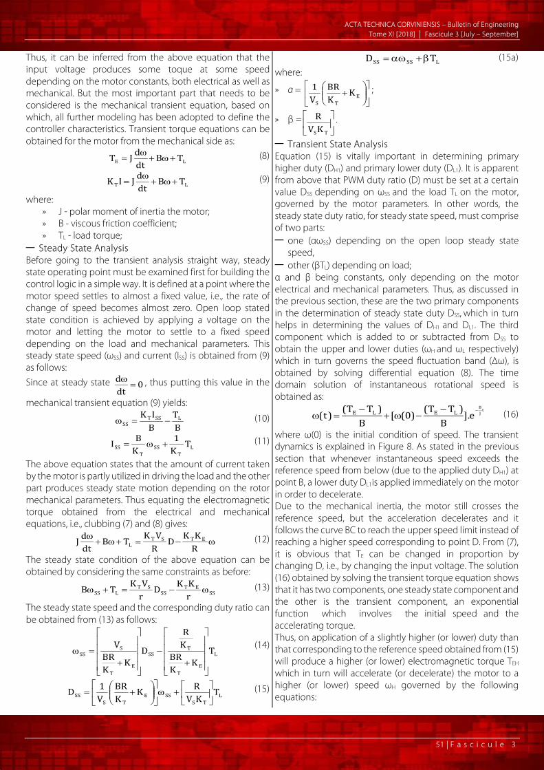
where ω(0) is the initial condition of speed. The transient dynamics is explained in Figure 8. As stated in the previous section that whenever instantaneous speed exceeds the reference speed from below (due to the applied duty DH1) at point B, a lower duty DL1is applied immediately on the motor in order to decelerate. Due to the mechanical inertia, the motor still crosses the reference speed, but the acceleration decelerates and it follows the curve BC to reach the upper speed limit instead of reaching a higher speed corresponding to point D. From (7), it is obvious that TE can be changed in proportion by changing D, i.e., by changing the input voltage. The solution (16) obtained by solving the transient torque equation shows that it has two components, one steady state component and the other is the transient component, an exponential function which involves the initial speed and the accelerating torque. Thus, on application of a slightly higher (or lower) duty than that corresponding to the reference speed obtained from (15) will produce a higher (or lower) electromagnetic torque TEH which in turn will accelerate (or decelerate) the motor to a higher (or lower) speed ωH governed by the following equations:
A CTA TECHNICA CORVINIENSIS – Bulletin of Engineering Tome XI [2018] | Fascicule 3 [July – September]
52 | F a s c i c u l e 3
tJB
tJB
e].B
)TT()0([
B)TT(
)t(
e].B
)TT()0([
B)TT(
)t(
LELLELL
LEHLEHH
−
−
−−ω−
−=ω
−−ω+
−=ω
(17)
Figure 8. Transient speed response
by the proposed controller The speed ripple thus can be found as:
)()( tt LH ωωω −=∆ (18) Thus from (18), for any speed ripple Δω depending on the tolerance level, corresponding electromagnetic torques can be found out from (17), which can be used to find the corresponding excess higher and lower duties (ΔDH1 and ΔDL1 respectively which comes out to be almost equal, say ΔD, if speed fluctuation is assumed to be symmetric about reference speed) from (15) where ωSS will have to be replaced by ωH and respectively ωL and ω(0) by reference speed. The additional duties ΔD thus obtained is added to DSS as obtained from (15) or (15a). Thus the final expression for duty ratios become as:
DDD SS1H ∆+= or DTD LSS1H ∆+β+αω= (19a)
DDD SS1L ∆+= or DTD LSS1L ∆−β+αω= (19b) Simulations are carried out for a maximum variation from the reference speed of about 10 rpm. From measurements, this duty ratio resulted in a speed ripple of about 3-8 rpm depending on the reference speed level and the load torque. — Steady State Motor Model in Frequency Domain For the purpose of analysis, the proposed digital controller is considered to be equivalent to a proportional controller. This analysis is made in order to observe if the actual motor speed reaches the reference speed at steady state with the proposed controller. The transfer function for a BLDC motor is shown as:
JL)KKBR(s
JL)BLJR(s
JLK
)s(V)s(
ET2
T
C ++
++
=ω (20)
where L - inductance of the motor; Other symbols bear the same meanings as before.
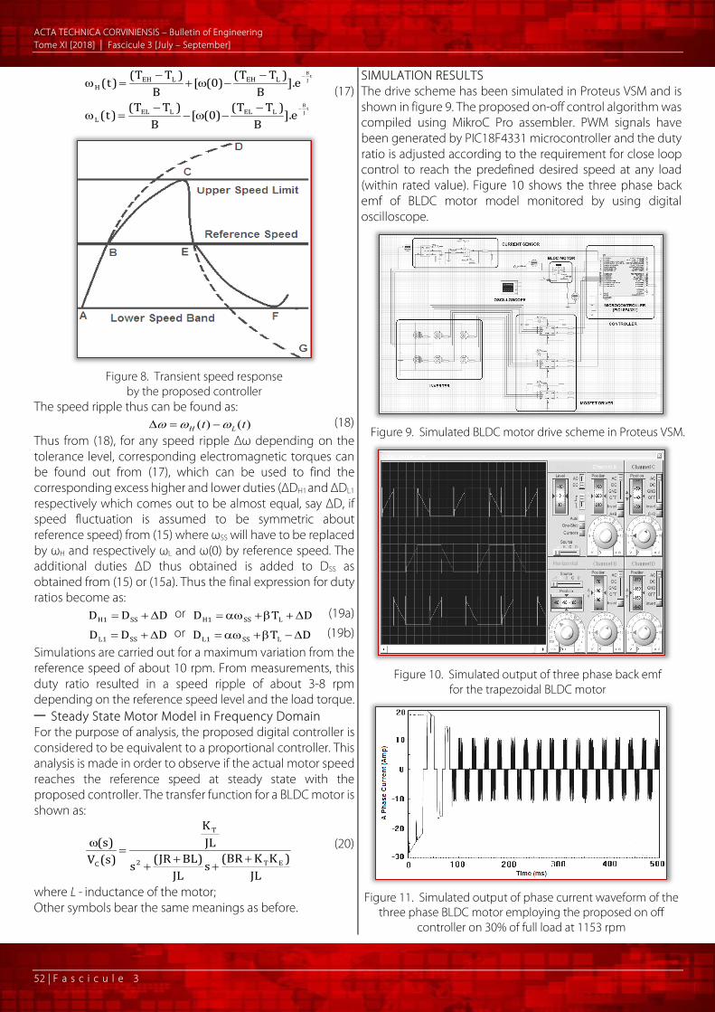
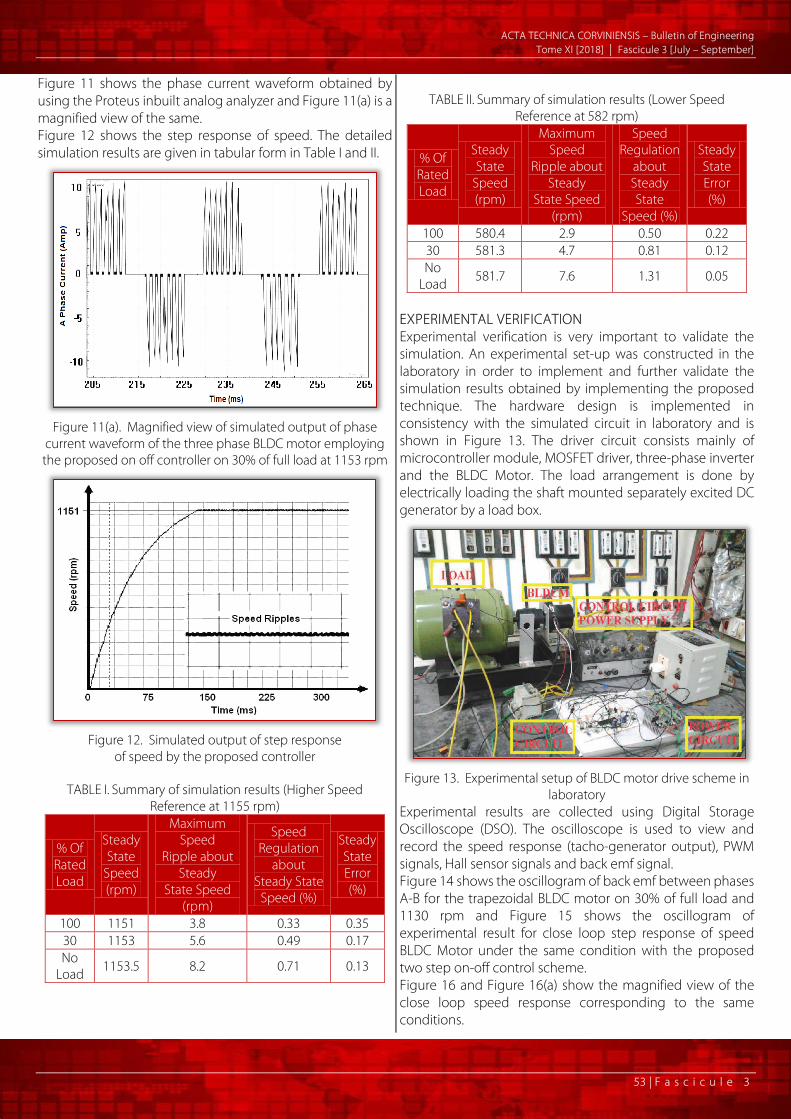
SIMULATION RESULTS The drive scheme has been simulated in Proteus VSM and is shown in figure 9. The proposed on-off control algorithm was compiled using MikroC Pro assembler. PWM signals have been generated by PIC18F4331 microcontroller and the duty ratio is adjusted according to the requirement for close loop control to reach the predefined desired speed at any load (within rated value). Figure 10 shows the three phase back emf of BLDC motor model monitored by using digital oscilloscope.
Figure 9. Simulated BLDC motor drive scheme in Proteus VSM.
Figure 10. Simulated output of three phase back emf
for the trapezoidal BLDC motor
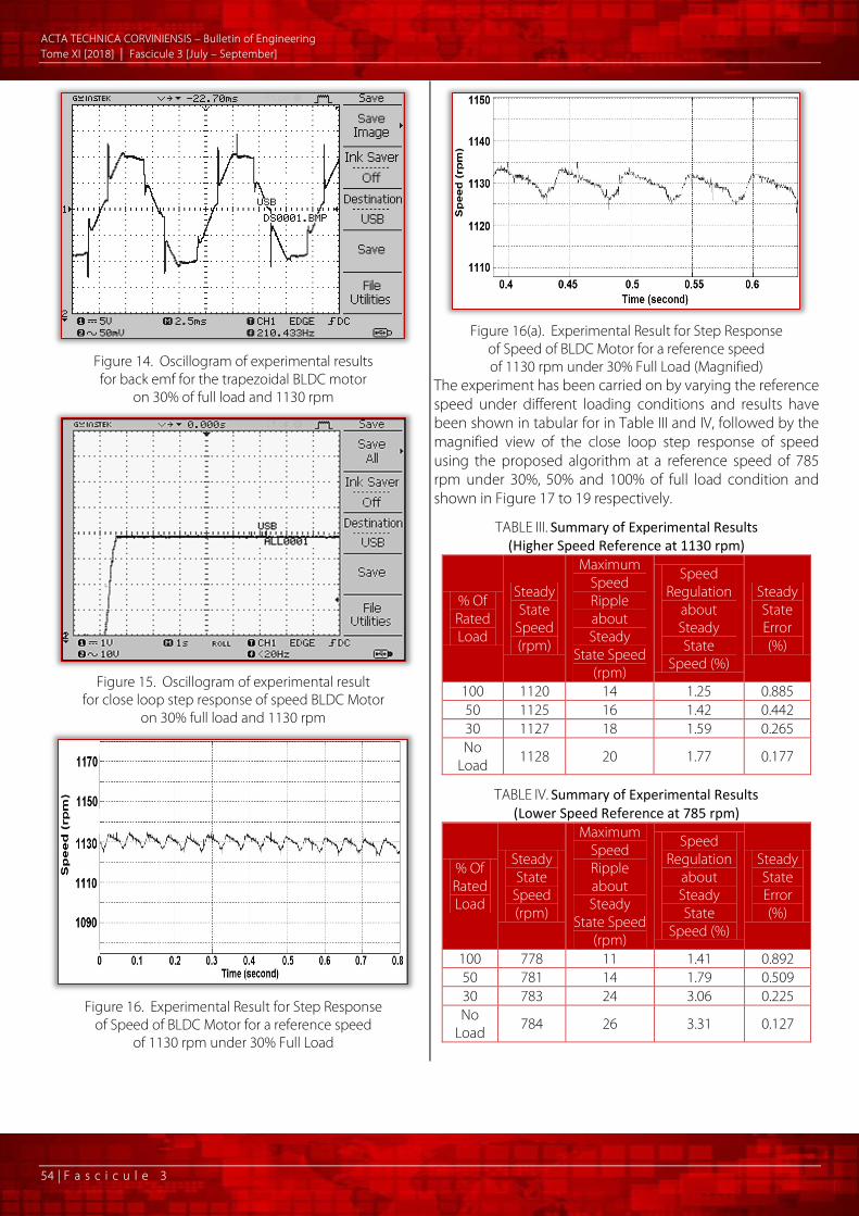
Figure 11. Simulated output of phase current waveform of the
three phase BLDC motor employing the proposed on off controller on 30% of full load at 1153 rpm
A CTA TECHNICA CORVINIENSIS – Bulletin of Engineering Tome XI [2018] | Fascicule 3 [July – September]
53 | F a s c i c u l e 3
Figure 11 shows the phase current waveform obtained by using the Proteus inbuilt analog analyzer and Figure 11(a) is a magnified view of the same. Figure 12 shows the step response of speed. The detailed simulation results are given in tabular form in Table I and II.
Figure 11(a). Magnified view of simulated output of phase
current waveform of the three phase BLDC motor employing the proposed on off controller on 30% of full load at 1153 rpm
Figure 12. Simulated output of step response
of speed by the proposed controller
TABLE I. Summary of simulation results (Higher Speed Reference at 1155 rpm)
% Of Rated Load
Steady State
Speed (rpm)
Maximum Speed
Ripple about Steady
State Speed (rpm)
Speed Regulation
about Steady State
Speed (%)
Steady State Error (%)
100 1151 3.8 0.33 0.35 30 1153 5.6 0.49 0.17 No
Load 1153.5 8.2 0.71 0.13
TABLE II. Summary of simulation results (Lower Speed
Reference at 582 rpm)
% Of Rated Load
Steady State
Speed (rpm)
Maximum Speed
Ripple about Steady
State Speed (rpm)
Speed Regulation
about Steady State
Speed (%)
Steady State Error (%)
100 580.4 2.9 0.50 0.22 30 581.3 4.7 0.81 0.12 No
Load 581.7 7.6 1.31 0.05
EXPERIMENTAL VERIFICATION Experimental verification is very important to validate the simulation. An experimental set-up was constructed in the laboratory in order to implement and further validate the simulation results obtained by implementing the proposed technique. The hardware design is implemented in consistency with the simulated circuit in laboratory and is shown in Figure 13. The driver circuit consists mainly of microcontroller module, MOSFET driver, three-phase inverter and the BLDC Motor. The load arrangement is done by electrically loading the shaft mounted separately excited DC generator by a load box.
Figure 13. Experimental setup of BLDC motor drive scheme in
laboratory Experimental results are collected using Digital Storage Oscilloscope (DSO). The oscilloscope is used to view and record the speed response (tacho-generator output), PWM signals, Hall sensor signals and back emf signal. Figure 14 shows the oscillogram of back emf between phases A-B for the trapezoidal BLDC motor on 30% of full load and 1130 rpm and Figure 15 shows the oscillogram of experimental result for close loop step response of speed BLDC Motor under the same condition with the proposed two step on-off control scheme. Figure 16 and Figure 16(a) show the magnified view of the close loop speed response corresponding to the same conditions.
A CTA TECHNICA CORVINIENSIS – Bulletin of Engineering Tome XI [2018] | Fascicule 3 [July – September]
54 | F a s c i c u l e 3
Figure 14. Oscillogram of experimental results for back emf for the trapezoidal BLDC motor
on 30% of full load and 1130 rpm
Figure 15. Oscillogram of experimental result
for close loop step response of speed BLDC Motor on 30% full load and 1130 rpm
Figure 16. Experimental Result for Step Response
of Speed of BLDC Motor for a reference speed of 1130 rpm under 30% Full Load
Figure 16(a). Experimental Result for Step Response
of Speed of BLDC Motor for a reference speed of 1130 rpm under 30% Full Load (Magnified)
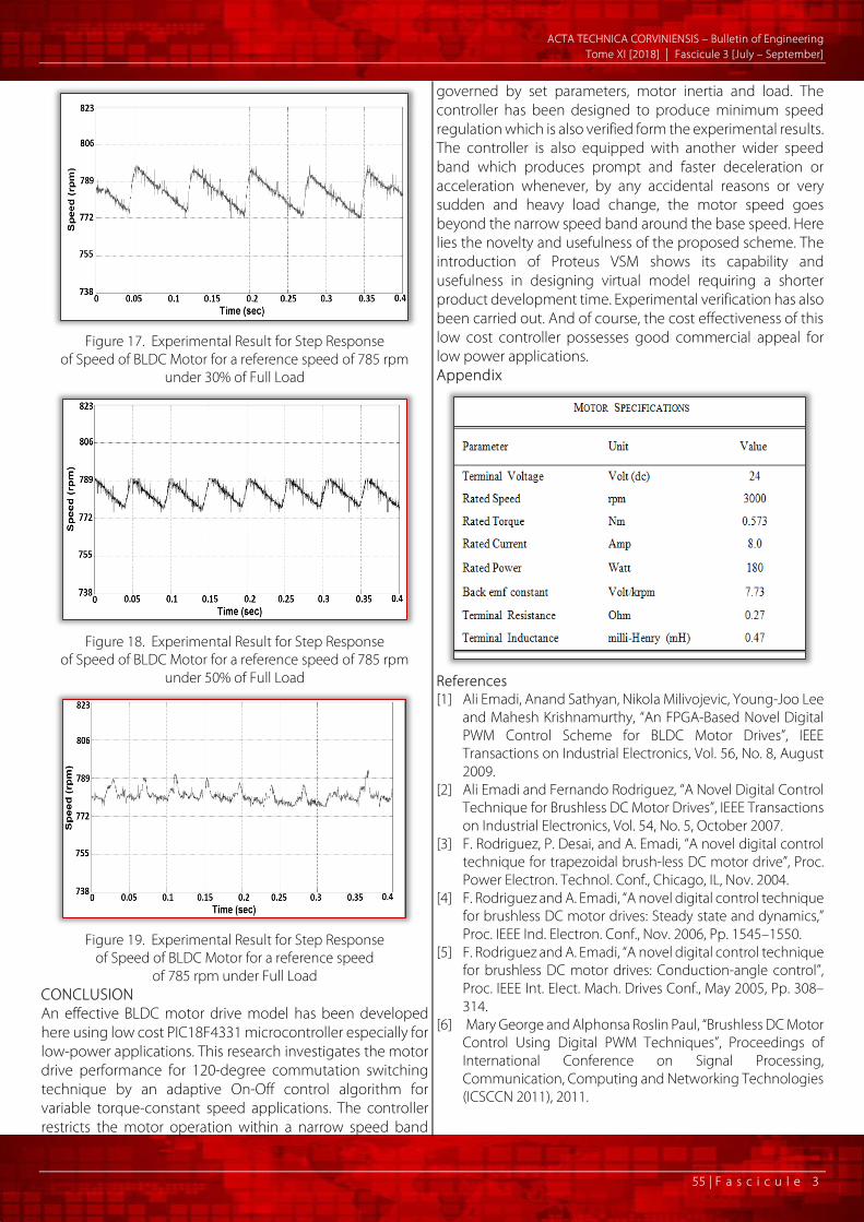
The experiment has been carried on by varying the reference speed under different loading conditions and results have been shown in tabular for in Table III and IV, followed by the magnified view of the close loop step response of speed using the proposed algorithm at a reference speed of 785 rpm under 30%, 50% and 100% of full load condition and shown in Figure 17 to 19 respectively.
TABLE III. Summary of Experimental Results (Higher Speed Reference at 1130 rpm)
% Of Rated Load
Steady State
Speed (rpm)
Maximum Speed Ripple about Steady
State Speed (rpm)
Speed Regulation
about Steady State
Speed (%)
Steady State Error (%)
100 1120 14 1.25 0.885 50 1125 16 1.42 0.442 30 1127 18 1.59 0.265 No
Load 1128 20 1.77 0.177
TABLE IV. Summary of Experimental Results (Lower Speed Reference at 785 rpm)
% Of Rated Load
Steady State
Speed (rpm)
Maximum Speed Ripple about Steady
State Speed (rpm)
Speed Regulation
about Steady State
Speed (%)
Steady State Error (%)
100 778 11 1.41 0.892 50 781 14 1.79 0.509 30 783 24 3.06 0.225 No
Load 784 26 3.31 0.127
A CTA TECHNICA CORVINIENSIS – Bulletin of Engineering Tome XI [2018] | Fascicule 3 [July – September]
55 | F a s c i c u l e 3
Figure 17. Experimental Result for Step Response
of Speed of BLDC Motor for a reference speed of 785 rpm under 30% of Full Load
Figure 18. Experimental Result for Step Response
of Speed of BLDC Motor for a reference speed of 785 rpm under 50% of Full Load
Figure 19. Experimental Result for Step Response
of Speed of BLDC Motor for a reference speed of 785 rpm under Full Load
CONCLUSION An effective BLDC motor drive model has been developed here using low cost PIC18F4331 microcontroller especially for low-power applications. This research investigates the motor drive performance for 120-degree commutation switching technique by an adaptive On-Off control algorithm for variable torque-constant speed applications. The controller restricts the motor operation within a narrow speed band
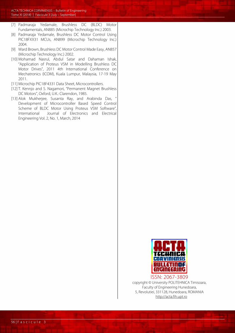
governed by set parameters, motor inertia and load. The controller has been designed to produce minimum speed regulation which is also verified form the experimental results. The controller is also equipped with another wider speed band which produces prompt and faster deceleration or acceleration whenever, by any accidental reasons or very sudden and heavy load change, the motor speed goes beyond the narrow speed band around the base speed. Here lies the novelty and usefulness of the proposed scheme. The introduction of Proteus VSM shows its capability and usefulness in designing virtual model requiring a shorter product development time. Experimental verification has also been carried out. And of course, the cost effectiveness of this low cost controller possesses good commercial appeal for low power applications. Appendix
References [1] Ali Emadi, Anand Sathyan, Nikola Milivojevic, Young-Joo Lee
and Mahesh Krishnamurthy, “An FPGA-Based Novel Digital PWM Control Scheme for BLDC Motor Drives”, IEEE Transactions on Industrial Electronics, Vol. 56, No. 8, August 2009.
[2] Ali Emadi and Fernando Rodriguez, “A Novel Digital Control Technique for Brushless DC Motor Drives”, IEEE Transactions on Industrial Electronics, Vol. 54, No. 5, October 2007.
[3] F. Rodriguez, P. Desai, and A. Emadi, “A novel digital control technique for trapezoidal brush-less DC motor drive”, Proc. Power Electron. Technol. Conf., Chicago, IL, Nov. 2004.
[4] F. Rodriguez and A. Emadi, “A novel digital control technique for brushless DC motor drives: Steady state and dynamics,” Proc. IEEE Ind. Electron. Conf., Nov. 2006, Pp. 1545–1550.
[5] F. Rodriguez and A. Emadi, “A novel digital control technique for brushless DC motor drives: Conduction-angle control”, Proc. IEEE Int. Elect. Mach. Drives Conf., May 2005, Pp. 308–314.
[6] Mary George and Alphonsa Roslin Paul, “Brushless DC Motor Control Using Digital PWM Techniques”, Proceedings of International Conference on Signal Processing, Communication, Computing and Networking Technologies (ICSCCN 2011), 2011.
A CTA TECHNICA CORVINIENSIS – Bulletin of Engineering Tome XI [2018] | Fascicule 3 [July – September]
56 | F a s c i c u l e 3
[7] Padmaraja Yedamale, Brushless DC (BLDC) Motor Fundamentals, AN885 (Microchip Technology Inc.) 2003.
[8] Padmaraja Yedamale, Brushless DC Motor Control Using PIC18FXX31 MCUs, AN899 (Microchip Technology Inc.) 2004.
[9] Ward Brown, Brushless DC Motor Control Made Easy, AN857 (Microchip Technology Inc.) 2002.
[10] Mohamad Nasrul, Abdul Satar and Dahaman Ishak, “Application of Proteus VSM in Modelling Brushless DC Motor Drives”, 2011 4th International Conference on Mechatronics (ICOM), Kuala Lumpur, Malaysia, 17-19 May 2011.
[11] Microchip PIC18F4331 Data Sheet, Microcontrollers. [12] T. Kennjo and S. Nagamori, “Permanent Magnet Brushless
DC Motors”, Oxford, U.K.: Clarendon, 1985. [13] Alok Mukherjee, Susanta Ray, and Arabinda Das, “
Development of Microcontroller Based Speed Control Scheme of BLDC Motor Using Proteus VSM Software”, International Journal of Electronics and Electrical Engineering Vol. 2, No. 1, March, 2014
ISSN: 2067-3809
copyright © University POLITEHNICA Timisoara, Faculty of Engineering Hunedoara,
5, Revolutiei, 331128, Hunedoara, ROMANIA http://acta.fih.upt.ro