Embed Size (px)
Citation preview
Dr.-Eng. E.h. Martin Herrenknecht Microtunneling with Herrenknecht MicroMachines Friday, March 28, 2003, Colorado School of Mines
Page 1 of 13
Microtunneling with Herrenknecht MicroMachines 1. Introduction Infrastructural measures are the base for a proper functioning of todays life and performance standards taking in account the private and economical aspects and expectations. Rising demands, further developments and requirements in reconstruction of existing infrastructure are one of the todays major challenges in keeping high level standards. The technology of installing underground infrastructural systems has been improved over the last decades. There is a basic devision to trench (conventional / open) method and trenchless construction methods. Microtunneling is characterised by: ⇒ Trenchless construction ⇒ Pipe Jacking ⇒ Remotely controlled execution ⇒ Most cost efficient method of pipe installation taking in account the direct and
indirect cost ⇒ Apart from start and reception shafts no further environmental, economical and
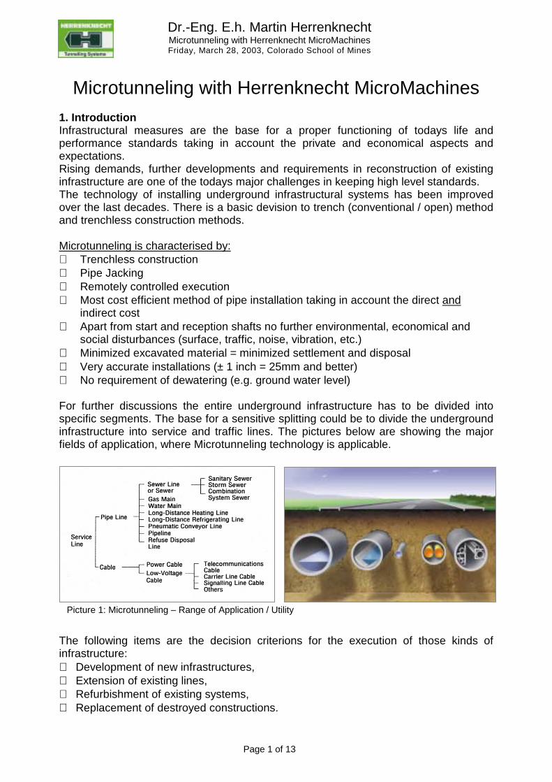
social disturbances (surface, traffic, noise, vibration, etc.) ⇒ Minimized excavated material = minimized settlement and disposal ⇒ Very accurate installations (± 1 inch = 25mm and better) ⇒ No requirement of dewatering (e.g. ground water level) For further discussions the entire underground infrastructure has to be divided into specific segments. The base for a sensitive splitting could be to divide the underground infrastructure into service and traffic lines. The pictures below are showing the major fields of application, where Microtunneling technology is applicable.
The following items are the decision criterions for the execution of those kinds of infrastructure: ⇒ Development of new infrastructures, ⇒ Extension of existing lines, ⇒ Refurbishment of existing systems, ⇒ Replacement of destroyed constructions.
Picture 1: Microtunneling – Range of Application / Utility
Dr.-Eng. E.h. Martin Herrenknecht Microtunneling with Herrenknecht MicroMachines Friday, March 28, 2003, Colorado School of Mines
Page 2 of 13
2. Herrenknecht AVN Technology 2.1 Introduction AVN stands for: Automatischer = automatic ⇒ the machine is remote controlled by a steering container Vortrieb = driving ⇒ tunneling Naß = wet ⇒ material conveyance via flushing (slurry) circuit These machines are designed as full face tunneling machines. The cutting wheel can be rotated in both directions. This enables the rolling effect to be corrected easily.
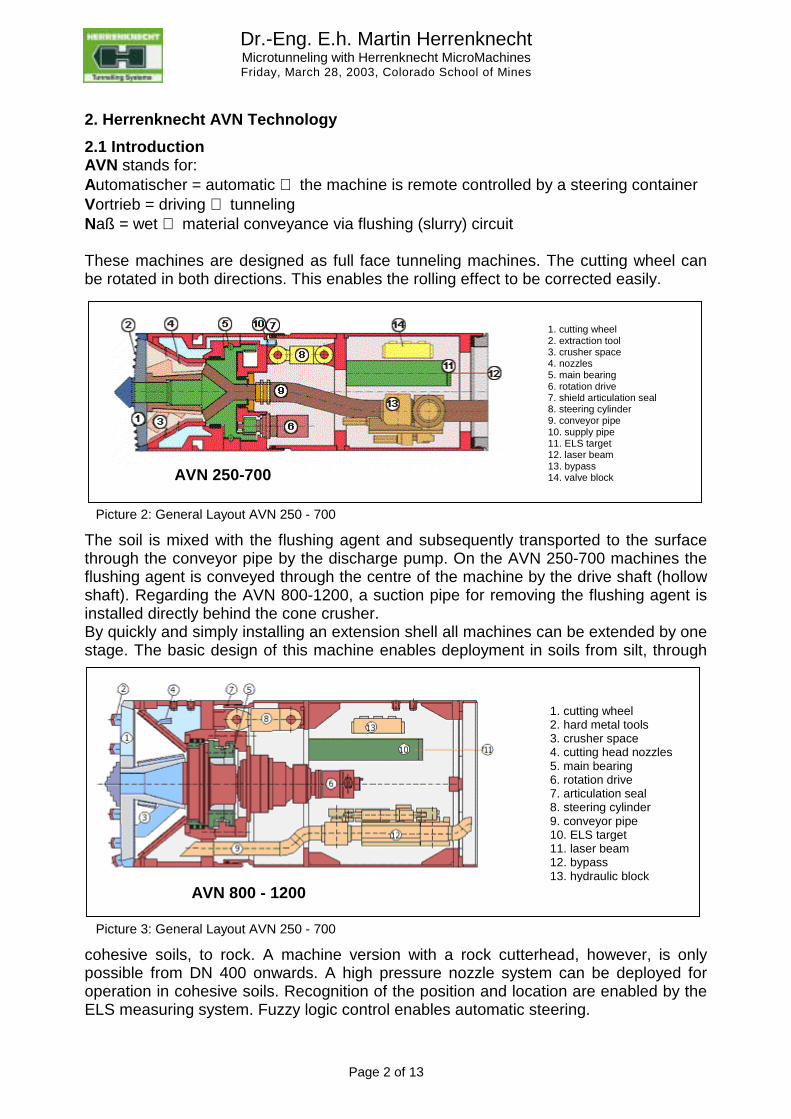
The soil is mixed with the flushing agent and subsequently transported to the surface through the conveyor pipe by the discharge pump. On the AVN 250-700 machines the flushing agent is conveyed through the centre of the machine by the drive shaft (hollow shaft). Regarding the AVN 800-1200, a suction pipe for removing the flushing agent is installed directly behind the cone crusher. By quickly and simply installing an extension shell all machines can be extended by one stage. The basic design of this machine enables deployment in soils from silt, through
cohesive soils, to rock. A machine version with a rock cutterhead, however, is only possible from DN 400 onwards. A high pressure nozzle system can be deployed for operation in cohesive soils. Recognition of the position and location are enabled by the ELS measuring system. Fuzzy logic control enables automatic steering.
1. cutting wheel2. extraction tool3. crusher space4. nozzles5. main bearing6. rotation drive7. shield articulation seal8. steering cylinder9. conveyor pipe10. supply pipe11. ELS target12. laser beam13. bypass14. valve blockAVN 250-700
Picture 2: General Layout AVN 250 - 700
1. cutting wheel2. hard metal tools3. crusher space4. cutting head nozzles5. main bearing6. rotation drive7. articulation seal8. steering cylinder9. conveyor pipe10. ELS target11. laser beam12. bypass13. hydraulic block
AVN 800 - 1200
Picture 3: General Layout AVN 250 - 700
Dr.-Eng. E.h. Martin Herrenknecht Microtunneling with Herrenknecht MicroMachines Friday, March 28, 2003, Colorado School of Mines
Page 3 of 13
The Herrenknecht Microtunnelling Machine Department has developed slurry shields of the
⇒ T series (T = Tür ⇒ Access Hatch) ⇒ D series ( D = Druckluft ⇒ Hydroshields)
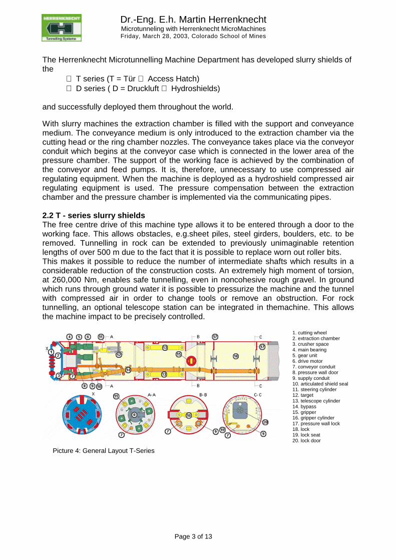
and successfully deployed them throughout the world. With slurry machines the extraction chamber is filled with the support and conveyance medium. The conveyance medium is only introduced to the extraction chamber via the cutting head or the ring chamber nozzles. The conveyance takes place via the conveyor conduit which begins at the conveyor case which is connected in the lower area of the pressure chamber. The support of the working face is achieved by the combination of the conveyor and feed pumps. It is, therefore, unnecessary to use compressed air regulating equipment. When the machine is deployed as a hydroshield compressed air regulating equipment is used. The pressure compensation between the extraction chamber and the pressure chamber is implemented via the communicating pipes. 2.2 T - series slurry shields The free centre drive of this machine type allows it to be entered through a door to the working face. This allows obstacles, e.g.sheet piles, steel girders, boulders, etc. to be removed. Tunnelling in rock can be extended to previously unimaginable retention lengths of over 500 m due to the fact that it is possible to replace worn out roller bits. This makes it possible to reduce the number of intermediate shafts which results in a considerable reduction of the construction costs. An extremely high moment of torsion, at 260,000 Nm, enables safe tunnelling, even in noncohesive rough gravel. In ground which runs through ground water it is possible to pressurize the machine and the tunnel with compressed air in order to change tools or remove an obstruction. For rock tunnelling, an optional telescope station can be integrated in themachine. This allows the machine impact to be precisely controlled.
1. cutting wheel2. extraction chamber3. crusher space4. main bearing5. gear unit6. drive motor7. conveyor conduit8. pressure wall door9. supply conduit10. articulated shield seal11. steering cylinder12. target13. telescope cylinder14. bypass15. gripper16. gripper cylinder17. pressure wall lock18. lock19. lock seat20. lock door
Picture 4: General Layout T-Series
Dr.-Eng. E.h. Martin Herrenknecht Microtunneling with Herrenknecht MicroMachines Friday, March 28, 2003, Colorado School of Mines
Page 4 of 13
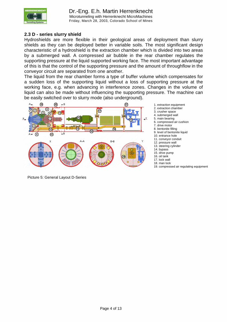
2.3 D - series slurry shield Hydroshields are more flexible in their geological areas of deployment than slurry shields as they can be deployed better in variable soils. The most significant design characteristic of a hydroshield is the extraction chamber which is divided into two areas by a submerged wall. A compressed air bubble in the rear chamber regulates the supporting pressure at the liquid supported working face. The most important advantage of this is that the control of the supporting pressure and the amount of throughflow in the conveyor circuit are separated from one another. The liquid from the rear chamber forms a type of buffer volume which compensates for a sudden loss of the supporting liquid without a loss of supporting pressure at the working face, e.g. when advancing in interference zones. Changes in the volume of liquid can also be made without influencing the supporting pressure. The machine can be easily switched over to slurry mode (also underground).
1. extraction equipment2. extraction chamber3. crusher space4. submerged wall5. main bearing6. compressed air cushion7. drive motor8. bentonite filling9. level of bentonite liquid10. entrance hole11. conveyor conduit12. pressure wall13. steering cylinder14. bypass15. drive pump16. oil tank17. lock wall18. man lock19. compressed air regulating equipment
Picture 5: General Layout D-Series
Dr.-Eng. E.h. Martin Herrenknecht Microtunneling with Herrenknecht MicroMachines Friday, March 28, 2003, Colorado School of Mines
Page 5 of 13
2.4 Water circuit The water circuit transports the soil during pipe jacking. It consists of the following components:
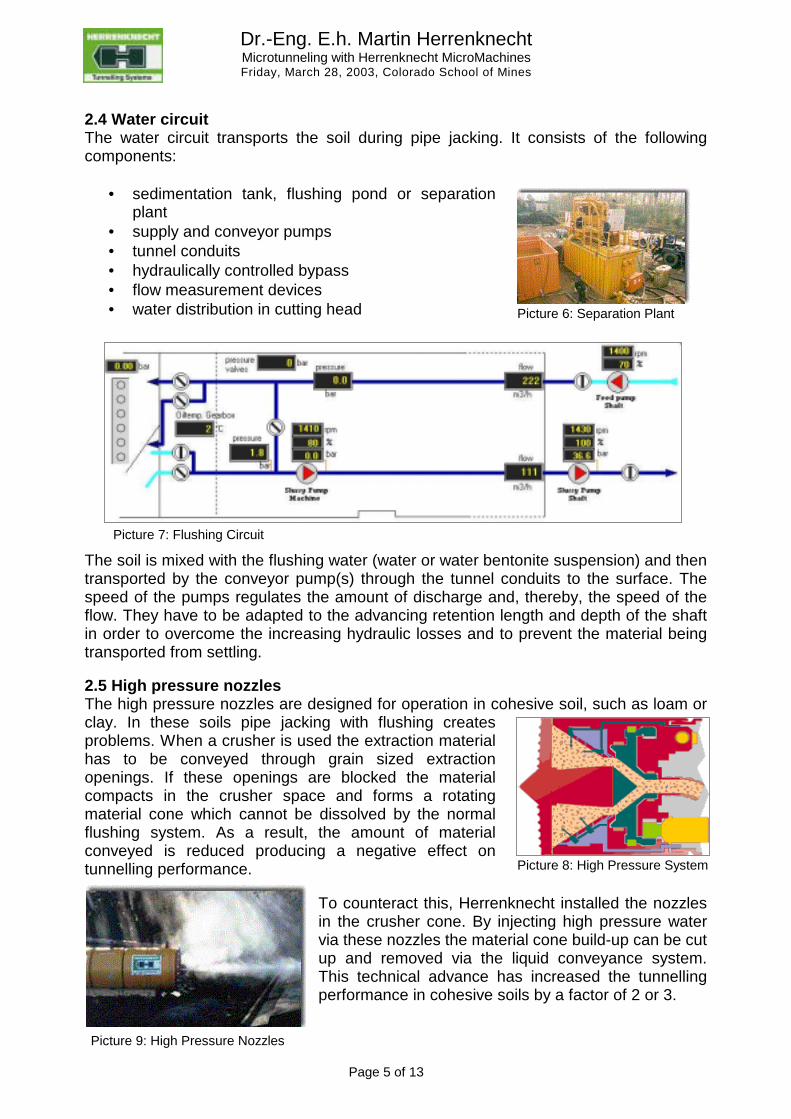
• sedimentation tank, flushing pond or separation plant
• supply and conveyor pumps • tunnel conduits • hydraulically controlled bypass • flow measurement devices • water distribution in cutting head
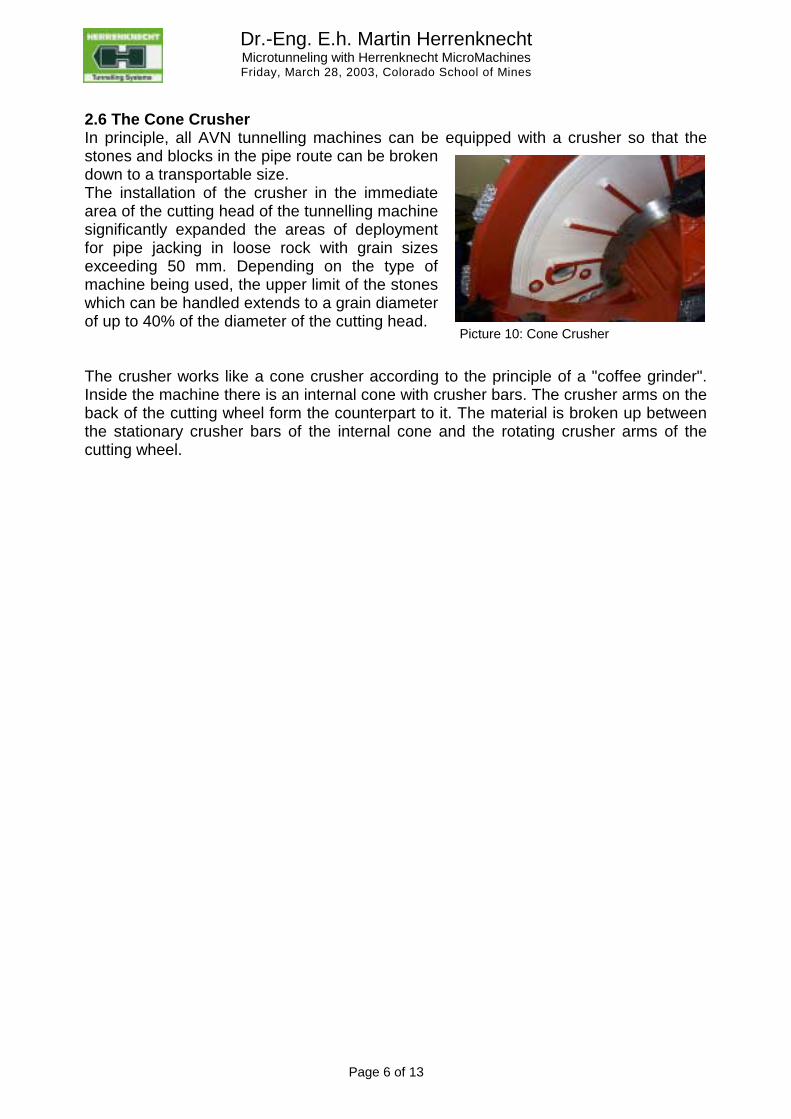
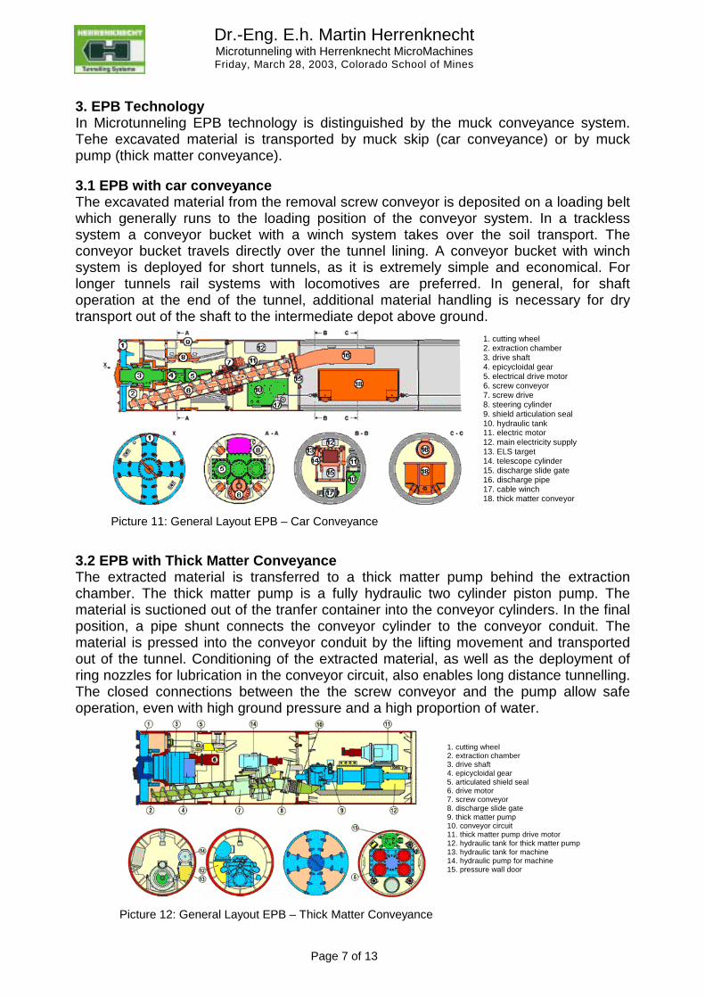
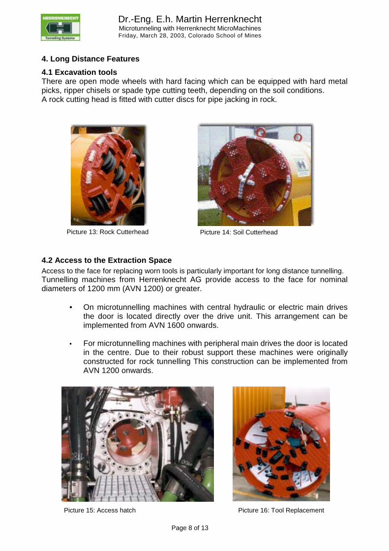
The soil is mixed with the flushing water (water or water bentonite suspension) and then transported by the conveyor pump(s) through the tunnel conduits to the surface. The speed of the pumps regulates the amount of discharge and, thereby, the speed of the flow. They have to be adapted to the advancing retention length and depth of the shaft in order to overcome the increasing hydraulic losses and to prevent the material being transported from settling. 2.5 High pressure nozzles The high pressure nozzles are designed for operation in cohesive soil, such as loam or clay. In these soils pipe jacking with flushing creates problems. When a crusher is used the extraction material has to be conveyed through grain sized extraction openings. If these openings are blocked the material compacts in the crusher space and forms a rotating material cone which cannot be dissolved by the normal flushing system. As a result, the amount of material conveyed is reduced producing a negative effect on tunnelling performance.
To counteract this, Herrenknecht installed the nozzles in the crusher cone. By injecting high pressure water via these nozzles the material cone build-up can be cut up and removed via the liquid conveyance system. This technical advance has increased the tunnelling performance in cohesive soils by a factor of 2 or 3.
Picture 6: Separation Plant
Picture 7: Flushing Circuit
Picture 8: High Pressure System
Picture 9: High Pressure Nozzles
Dr.-Eng. E.h. Martin Herrenknecht Microtunneling with Herrenknecht MicroMachines Friday, March 28, 2003, Colorado School of Mines
Page 6 of 13
2.6 The Cone Crusher In principle, all AVN tunnelling machines can be equipped with a crusher so that the stones and blocks in the pipe route can be broken down to a transportable size. The installation of the crusher in the immediate area of the cutting head of the tunnelling machine significantly expanded the areas of deployment for pipe jacking in loose rock with grain sizes exceeding 50 mm. Depending on the type of machine being used, the upper limit of the stones which can be handled extends to a grain diameter of up to 40% of the diameter of the cutting head. The crusher works like a cone crusher according to the principle of a "coffee grinder". Inside the machine there is an internal cone with crusher bars. The crusher arms on the back of the cutting wheel form the counterpart to it. The material is broken up between the stationary crusher bars of the internal cone and the rotating crusher arms of the cutting wheel.
Picture 10: Cone Crusher
Dr.-Eng. E.h. Martin Herrenknecht Microtunneling with Herrenknecht MicroMachines Friday, March 28, 2003, Colorado School of Mines
Page 7 of 13
3. EPB Technology In Microtunneling EPB technology is distinguished by the muck conveyance system. Tehe excavated material is transported by muck skip (car conveyance) or by muck pump (thick matter conveyance). 3.1 EPB with car conveyance The excavated material from the removal screw conveyor is deposited on a loading belt which generally runs to the loading position of the conveyor system. In a trackless system a conveyor bucket with a winch system takes over the soil transport. The conveyor bucket travels directly over the tunnel lining. A conveyor bucket with winch system is deployed for short tunnels, as it is extremely simple and economical. For longer tunnels rail systems with locomotives are preferred. In general, for shaft operation at the end of the tunnel, additional material handling is necessary for dry transport out of the shaft to the intermediate depot above ground.
3.2 EPB with Thick Matter Conveyance The extracted material is transferred to a thick matter pump behind the extraction chamber. The thick matter pump is a fully hydraulic two cylinder piston pump. The material is suctioned out of the tranfer container into the conveyor cylinders. In the final position, a pipe shunt connects the conveyor cylinder to the conveyor conduit. The material is pressed into the conveyor conduit by the lifting movement and transported out of the tunnel. Conditioning of the extracted material, as well as the deployment of ring nozzles for lubrication in the conveyor circuit, also enables long distance tunnelling. The closed connections between the the screw conveyor and the pump allow safe operation, even with high ground pressure and a high proportion of water.
1. cutting wheel2. extraction chamber3. drive shaft4. epicycloidal gear5. electrical drive motor6. screw conveyor7. screw drive8. steering cylinder9. shield articulation seal10. hydraulic tank11. electric motor12. main electricity supply13. ELS target14. telescope cylinder15. discharge slide gate16. discharge pipe17. cable winch18. thick matter conveyor
Picture 11: General Layout EPB – Car Conveyance
1. cutting wheel2. extraction chamber3. drive shaft4. epicycloidal gear5. articulated shield seal6. drive motor7. screw conveyor8. discharge slide gate9. thick matter pump10. conveyor circuit11. thick matter pump drive motor12. hydraulic tank for thick matter pump13. hydraulic tank for machine14. hydraulic pump for machine15. pressure wall door
Picture 12: General Layout EPB – Thick Matter Conveyance
Dr.-Eng. E.h. Martin Herrenknecht Microtunneling with Herrenknecht MicroMachines Friday, March 28, 2003, Colorado School of Mines
Page 8 of 13
4. Long Distance Features 4.1 Excavation tools There are open mode wheels with hard facing which can be equipped with hard metal picks, ripper chisels or spade type cutting teeth, depending on the soil conditions. A rock cutting head is fitted with cutter discs for pipe jacking in rock.
4.2 Access to the Extraction Space Access to the face for replacing worn tools is particularly important for long distance tunnelling. Tunnelling machines from Herrenknecht AG provide access to the face for nominal diameters of 1200 mm (AVN 1200) or greater.
• On microtunnelling machines with central hydraulic or electric main drives the door is located directly over the drive unit. This arrangement can be implemented from AVN 1600 onwards.
• For microtunnelling machines with peripheral main drives the door is located
in the centre. Due to their robust support these machines were originally constructed for rock tunnelling This construction can be implemented from AVN 1200 onwards.
Picture 13: Rock Cutterhead Picture 14: Soil Cutterhead
Picture 15: Access hatch Picture 16: Tool Replacement
Dr.-Eng. E.h. Martin Herrenknecht Microtunneling with Herrenknecht MicroMachines Friday, March 28, 2003, Colorado School of Mines
Page 9 of 13
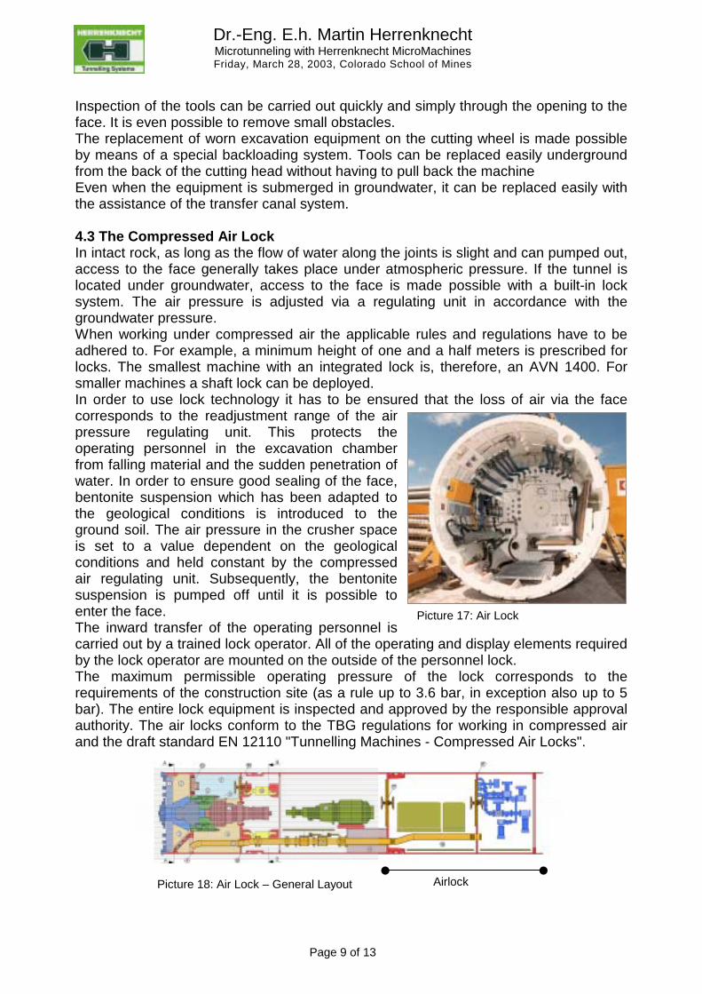
Inspection of the tools can be carried out quickly and simply through the opening to the face. It is even possible to remove small obstacles. The replacement of worn excavation equipment on the cutting wheel is made possible by means of a special backloading system. Tools can be replaced easily underground from the back of the cutting head without having to pull back the machine Even when the equipment is submerged in groundwater, it can be replaced easily with the assistance of the transfer canal system. 4.3 The Compressed Air Lock In intact rock, as long as the flow of water along the joints is slight and can pumped out, access to the face generally takes place under atmospheric pressure. If the tunnel is located under groundwater, access to the face is made possible with a built-in lock system. The air pressure is adjusted via a regulating unit in accordance with the groundwater pressure. When working under compressed air the applicable rules and regulations have to be adhered to. For example, a minimum height of one and a half meters is prescribed for locks. The smallest machine with an integrated lock is, therefore, an AVN 1400. For smaller machines a shaft lock can be deployed. In order to use lock technology it has to be ensured that the loss of air via the face corresponds to the readjustment range of the air pressure regulating unit. This protects the operating personnel in the excavation chamber from falling material and the sudden penetration of water. In order to ensure good sealing of the face, bentonite suspension which has been adapted to the geological conditions is introduced to the ground soil. The air pressure in the crusher space is set to a value dependent on the geological conditions and held constant by the compressed air regulating unit. Subsequently, the bentonite suspension is pumped off until it is possible to enter the face. The inward transfer of the operating personnel is carried out by a trained lock operator. All of the operating and display elements required by the lock operator are mounted on the outside of the personnel lock. The maximum permissible operating pressure of the lock corresponds to the requirements of the construction site (as a rule up to 3.6 bar, in exception also up to 5 bar). The entire lock equipment is inspected and approved by the responsible approval authority. The air locks conform to the TBG regulations for working in compressed air and the draft standard EN 12110 "Tunnelling Machines - Compressed Air Locks".
Picture 17: Air Lock
Airlock Picture 18: Air Lock – General Layout
Dr.-Eng. E.h. Martin Herrenknecht Microtunneling with Herrenknecht MicroMachines Friday, March 28, 2003, Colorado School of Mines
Page 10 of 13
4.4 Intermediate jacking stations For long tunnel advances intermediate jacking stations are necessary in order to avoid exceeding the maximum allowable jacking force for an individual tunnel pipe. Reusable steel interjacks, which are removed after tunnelling, are usually used for small diameters up to DN 900.
From DN 1000, single use interjacks made of the same material as the product pipe are used. For these, only the interjack jacking cylinders are dismantled after tunnelling. The seal between the single use interjacks and the product pipe is made with a seal for which the tension can be adjusted. The interjacks are advanced with the hydraulics from the control container or, for longer retention lengths, with an additional hydraulic power pack installed in the pipe conduit or in the tunnelling machine.
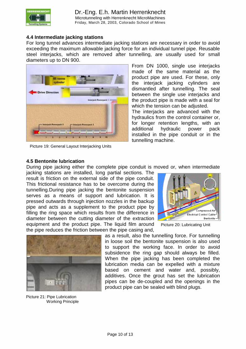
4.5 Bentonite lubrication During pipe jacking either the complete pipe conduit is moved or, when intermediate jacking stations are installed, long partial sections. The result is friction on the external side of the pipe conduit. This frictional resistance has to be overcome during the tunnelling.During pipe jacking the bentonite suspension serves as a means of support and lubrication. It is pressed outwards through injection nozzles in the backup pipe and acts as a supplement to the product pipe by filling the ring space which results from the difference in diameter between the cutting diameter of the extraction equipment and the product pipe. The liquid film around the pipe reduces the friction between the pipe casing and,
as a result, also the tunnelling force. For tunnelling in loose soil the bentonite suspension is also used to support the working face. In order to avoid subsidence the ring gap should always be filled. When the pipe jacking has been completed the lubrication media can be expelled with a mixture based on cement and water and, possibly, additives. Once the grout has set the lubrication pipes can be de-coupled and the openings in the product pipe can be sealed with blind plugs.
Picture 19: General Layout Interjacking Units
Picture 20: Lubricating Unit
Picture 21: Pipe Lubrication Working Principle
Dr.-Eng. E.h. Martin Herrenknecht Microtunneling with Herrenknecht MicroMachines Friday, March 28, 2003, Colorado School of Mines
Page 11 of 13
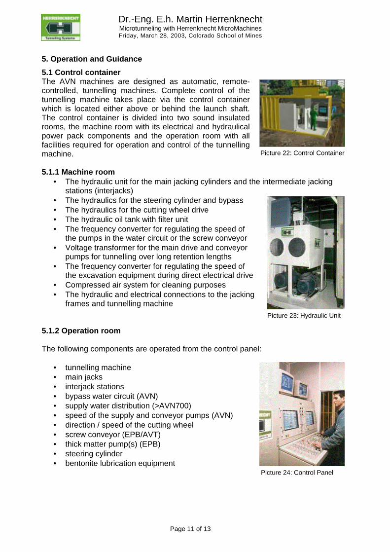
5. Operation and Guidance 5.1 Control container The AVN machines are designed as automatic, remote-controlled, tunnelling machines. Complete control of the tunnelling machine takes place via the control container which is located either above or behind the launch shaft. The control container is divided into two sound insulated rooms, the machine room with its electrical and hydraulical power pack components and the operation room with all facilities required for operation and control of the tunnelling machine. 5.1.1 Machine room
• The hydraulic unit for the main jacking cylinders and the intermediate jacking stations (interjacks)
• The hydraulics for the steering cylinder and bypass • The hydraulics for the cutting wheel drive • The hydraulic oil tank with filter unit • The frequency converter for regulating the speed of
the pumps in the water circuit or the screw conveyor • Voltage transformer for the main drive and conveyor
pumps for tunnelling over long retention lengths • The frequency converter for regulating the speed of
the excavation equipment during direct electrical drive • Compressed air system for cleaning purposes • The hydraulic and electrical connections to the jacking
frames and tunnelling machine 5.1.2 Operation room The following components are operated from the control panel:
• tunnelling machine • main jacks • interjack stations • bypass water circuit (AVN) • supply water distribution (>AVN700) • speed of the supply and conveyor pumps (AVN) • direction / speed of the cutting wheel • screw conveyor (EPB/AVT) • thick matter pump(s) (EPB) • steering cylinder • bentonite lubrication equipment
Picture 22: Control Container
Picture 23: Hydraulic Unit
Picture 24: Control Panel
Dr.-Eng. E.h. Martin Herrenknecht Microtunneling with Herrenknecht MicroMachines Friday, March 28, 2003, Colorado School of Mines
Page 12 of 13
5.2 ELS (Electronic Laser System) Control system for pipe jacking In order to recognise the position of the Tunnel Boring Machine (TBM) (horizontal and vertical deviations, the pitch and roll tendency of the machine, the yaw angle) suitable sensor technology is necessary to guide a TBM. ELS is an intelligent sensor unit with a sturdy metal case. The device is roughly the size of a shoebox and is watertight up to 5 metres submersion. It is dry-filled with an inert gas under slight pressure. The ELS is installed on the back of the tunnelling machine so that the guidance laser makes contact with the target. The device is connected via a cable which supplies the power and transmits the measurement results. The measurement data are transmitted to a computer via a special receiver device ELS-PCA. Software in the form of a TurboPascal Unit is runs on the computer. This processes the measurement data and passes it on to the user program. The ELS system consists of the following components:
• the ELS device • the ELS-PCA receiver component • the ELS-TPU TurboPascal Unit
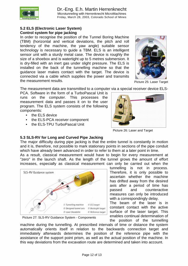
5.3 SLS-RV for Long and Curved Pipe Jacking The major difficulty during pipe jacking is that the entire tunnel is constantly in motion and it is, therefore, not possible to mark stationary points in sections of the pipe conduit which have already been advanced in order to refer to them at a later point in time. As a result, classical measurement would have to begin for every measurement at "zero" in the launch shaft. As the length of the tunnel grows the amount of effort increases, especially as classical measurement can only be carried out when the
tunnelling is not in process. Therefore, it is only possible to ascertain whether the machine has drifted away from the desired axis after a period of time has passed and counteractive measures can only be introduced with a correspondingly delay. The beam of the laser is in constant contact with the active surface of the laser target. This enables continual determination of the position of the tunnelling
machine during the tunnelling. At prescribed intervals of time or distance the system automatically orients itself in relation to the backwards connection target and immediately afterwards determines the position of the reference pipe with the assistance of the support point prism, as well as the actual position of the machine. In this way deviations from the excavation route are determined and taken into account.
Picture 25: Laser Target
Picture 26: Laser and Target
Picture 27: SLS-RV Guidance System - Components
Dr.-Eng. E.h. Martin Herrenknecht Microtunneling with Herrenknecht MicroMachines Friday, March 28, 2003, Colorado School of Mines
Page 13 of 13
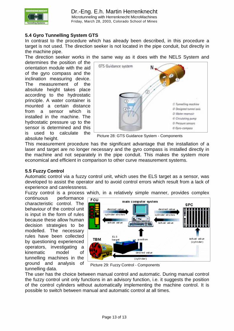
5.4 Gyro Tunnelling System GTS In contrast to the procedure which has already been described, in this procedure a target is not used. The direction seeker is not located in the pipe conduit, but directly in the machine pipe. The direction seeker works in the same way as it does with the NELS System and determines the position of the orientation module with the aid of the gyro compass and the inclination measuring device. The measurement of the absolute height takes place according to the hydrostatic principle. A water container is mounted a certain distance from a sensor which is installed in the machine. The hydrostatic pressure up to the sensor is determined and this is used to calculate the absolute height. This measurement procedure has the significant advantage that the installation of a laser and target are no longer necessary and the gyro compass is installed directly in the machine and not separately in the pipe conduit. This makes the system more economical and efficient in comparison to other curve measurement systems. 5.5 Fuzzy Control Automatic control via a fuzzy control unit, which uses the ELS target as a sensor, was developed to assist the operator and to avoid control errors which result from a lack of experience and carelessness. Fuzzy control is a process which, in a relatively simple manner, provides complex continuous performance characteristic control. The behaviour of the control unit is input in the form of rules because these allow human decision strategies to be modelled. The necessary rules have been collected by questioning experienced operators, investigating a kinematic model of tunnelling machines in the ground and analysis of tunnelling data. The user has the choice between manual control and automatic. During manual control the fuzzy control unit only functions in an advisory function, i.e. it suggests the position of the control cylinders without automatically implementing the machine control. It is possible to switch between manual and automatic control at all times.
Picture 28: GTS Guidance System - Components
Picture 29: Fuzzy Control - Components