Embed Size (px)
Citation preview
Issue 3 TIL – Eng – Spec – 061 MiniKing OEM Sonar OIM
Supplied by
MiniKing OEM Sonar
Operator & Installation
Manual
The electronic version of this document is the controlled copy. Therefore all printed versions of this document are uncontrolled.

F063.1
COPYRIGHT
© Tritech International Limited
The copyright in this document is the property of Tritech International Limited. The document is supplied by Tritech International Limited on the understanding that it may not be copied, used, or disclosed to others except as authorised in writing by Tritech International Limited. Tritech International Limited reserves the right to change, modify and update designs and specifications as part of their ongoing product development programme.
Tritech International Ltd MiniKing OEM Sonar OIM
Issue 3 TIL – Eng – Spec – 061 Page 4 of 44
Table of Contents
WARRANTY STATEMENT ................................................................................................................5
TRADEMARKS...................................................................................................................................6
Safety Statements .............................................................................................................................7
Technical Support .............................................................................................................................7
PART 1. SOFTWARE INSTALLATION (WIN98/2000/XP) ................................................................8
PART 2. HARDWARE INSTALLATION.............................................................................................8 Power...............................................................................................................................................8 Communication protocol ..................................................................................................................8 Third Party Communication Devices ...............................................................................................9 System Interconnect Cabling.........................................................................................................10 Further Information ........................................................................................................................13
PART 3. OPERATION OF THE MINIKING SONAR APPLICATION ..............................................14 Description of Screen Display and Control Areas .........................................................................15 Menu Bar Options..........................................................................................................................15 Sonar Settings ...............................................................................................................................20 Application Tools ...........................................................................................................................22 Status bar.......................................................................................................................................24 Sidebar...........................................................................................................................................25 Using the Elastic Band for measurement ......................................................................................26 Dynamic Range and Sonar Rx Indicator .......................................................................................26
MAINTENANCE................................................................................................................................28 MiniKing Head maintenance..........................................................................................................28 Cables............................................................................................................................................28 Computer .......................................................................................................................................28 The Sonar software can be reloaded as follows…........................................................................28
APPENDIX A: MINIKING SETUP PROGRAM ................................................................................29 Configuring Com Port and Baud Rates .........................................................................................30 Configuring a COM Port for GPS input..........................................................................................33
APPENDIX B: MINIKING AUX PORT..............................................................................................34 Introduction ....................................................................................................................................34 Sonar AUX Port Wiring ..................................................................................................................34 Compatible Devices.......................................................................................................................34 Configuring MiniKing for AUX Serial I/O........................................................................................35
SOFTWARE SETTINGS ..........................................................................................................................36 INSTANCE 1: DIGIQUARTZ PRESSURE STRING TYPE...........................................................................36
Compatible Digiquartz configurations............................................................................................36 Output Modes ................................................................................................................................38
INSTANCE 2: TRITECH RS-232 ALTIMETER STRING TYPE ............................................................39 Compatible Altimeter configurations..............................................................................................39 Output Mode Examples .................................................................................................................41
INSTANCE 3: MDL/TCM2 GYRO STRING TYPE ..................................................................................42 Output Modes ................................................................................................................................42 REGIONAL SETTINGS and AUX data..........................................................................................43
SERIAL PORT OUTPUT USING REMV4 UTILITY PROGRAM......................................................................43 REMV4 Software Setup for Sonar Aux Data Output .....................................................................44
Tritech International Ltd MiniKing OEM Sonar OIM
Issue 3 TIL – Eng – Spec – 061 Page 5 of 44
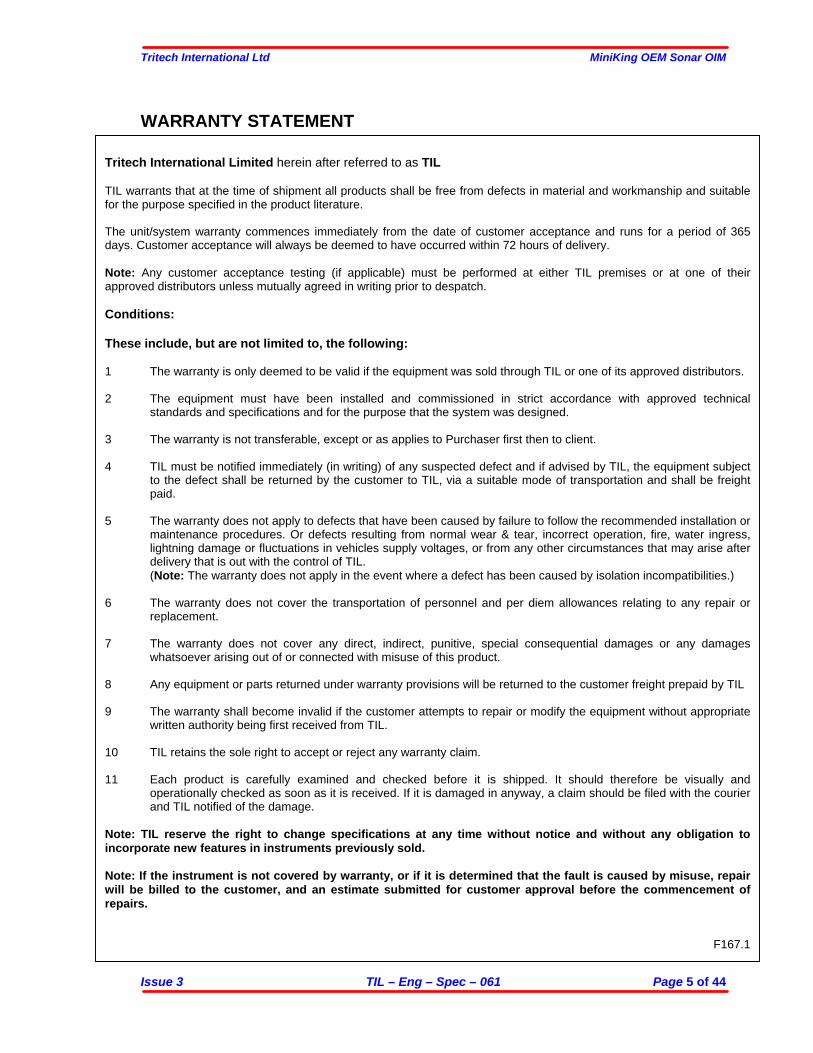
WARRANTY STATEMENT
Tritech International Limited herein after referred to as TIL TIL warrants that at the time of shipment all products shall be free from defects in material and workmanship and suitable for the purpose specified in the product literature. The unit/system warranty commences immediately from the date of customer acceptance and runs for a period of 365 days. Customer acceptance will always be deemed to have occurred within 72 hours of delivery. Note: Any customer acceptance testing (if applicable) must be performed at either TIL premises or at one of their approved distributors unless mutually agreed in writing prior to despatch. Conditions: These include, but are not limited to, the following: 1 The warranty is only deemed to be valid if the equipment was sold through TIL or one of its approved distributors. 2 The equipment must have been installed and commissioned in strict accordance with approved technical
standards and specifications and for the purpose that the system was designed. 3 The warranty is not transferable, except or as applies to Purchaser first then to client. 4 TIL must be notified immediately (in writing) of any suspected defect and if advised by TIL, the equipment subject
to the defect shall be returned by the customer to TIL, via a suitable mode of transportation and shall be freight paid.
5 The warranty does not apply to defects that have been caused by failure to follow the recommended installation or
maintenance procedures. Or defects resulting from normal wear & tear, incorrect operation, fire, water ingress, lightning damage or fluctuations in vehicles supply voltages, or from any other circumstances that may arise after delivery that is out with the control of TIL. (Note: The warranty does not apply in the event where a defect has been caused by isolation incompatibilities.)
6 The warranty does not cover the transportation of personnel and per diem allowances relating to any repair or
replacement. 7 The warranty does not cover any direct, indirect, punitive, special consequential damages or any damages
whatsoever arising out of or connected with misuse of this product. 8 Any equipment or parts returned under warranty provisions will be returned to the customer freight prepaid by TIL 9 The warranty shall become invalid if the customer attempts to repair or modify the equipment without appropriate
written authority being first received from TIL. 10 TIL retains the sole right to accept or reject any warranty claim. 11 Each product is carefully examined and checked before it is shipped. It should therefore be visually and
operationally checked as soon as it is received. If it is damaged in anyway, a claim should be filed with the courier and TIL notified of the damage.
Note: TIL reserve the right to change specifications at any time without notice and without any obligation to incorporate new features in instruments previously sold. Note: If the instrument is not covered by warranty, or if it is determined that the fault is caused by misuse, repair will be billed to the customer, and an estimate submitted for customer approval before the commencement of repairs.
F167.1

Tritech International Ltd MiniKing OEM Sonar OIM
Issue 3 TIL – Eng – Spec – 061 Page 6 of 44
TRADEMARKS Microsoft and Windows 98 are registered trademarks of the Microsoft Corporation IBM and AT are registered trademarks of International Business Computers. AMD is a registered trademark of Advanced Micro Devices. Intel is a trademark of Intel Corporation Whilst every effort is taken to keep all the information contained in this document up to date, information in this document is subject to change without notice and does not represent a commitment on the part of Tritech International or System Technologies. No part of this manual may be reproduced or transmitted in any form or by any means, including photocopying or recording for any purpose without the express written permission of Tritech International. © System Technologies, Tritech International Ltd.
Tritech International Ltd MiniKing OEM Sonar OIM
Issue 3 TIL – Eng – Spec – 061 Page 7 of 44
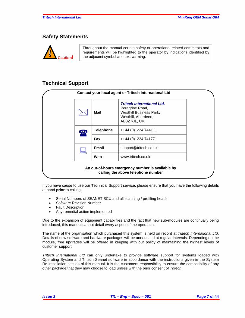
Safety Statements
Caution!
Technical Support
Contact your local agent or Tritech International Ltd
Tritech International Ltd. Peregrine Road, Westhill Business Park, Westhill, Aberdeen, AB32 6JL, UK
Telephone ++44 (0)1224 744111 Fax ++44 (0)1224 741771
Email [email protected] Web www.tritech.co.uk
An out-of-hours emergency number is available by
calling the above telephone number If you have cause to use our Technical Support service, please ensure that you have the following details at hand prior to calling:
• Serial Numbers of SEANET SCU and all scanning / profiling heads • Software Revision Number • Fault Description • Any remedial action implemented
Due to the expansion of equipment capabilities and the fact that new sub-modules are continually being introduced, this manual cannot detail every aspect of the operation. The name of the organisation which purchased this system is held on record at Tritech International Ltd. Details of new software and hardware packages will be announced at regular intervals. Depending on the module, free upgrades will be offered in keeping with our policy of maintaining the highest levels of customer support. Tritech International Ltd can only undertake to provide software support for systems loaded with Operating System and Tritech Seanet software in accordance with the instructions given in the System Re-installation section of this manual. It is the customers responsibility to ensure the compatibility of any other package that they may choose to load unless with the prior consent of Tritech.
Throughout the manual certain safety or operational related comments and requirements will be highlighted to the operator by indications identified by the adjacent symbol and text warning.
Tritech International Ltd MiniKing OEM Sonar OIM
Issue 3 TIL – Eng – Spec – 061 Page 8 of 44
PART 1. SOFTWARE INSTALLATION (WIN98/2000/XP)
PC Hardware Requirements: Pentium PC 32MB RAM (Win98), 128MB (Win2000/XP) 10MB Hard Disk Space (Installation) Available COM Port (115.2kBaud capable) 16-Bit Colour Graphics Card at 800x600 Resolution
I. Insert the ‘MiniKing Sonar’ Installation CD into drive and run SETUP.EXE.
II. The Installation will place 2 shortcuts on the Desktop; i) MiniKing Setup ii) MiniKing Sonar.
III. The MiniKing Sonar software is pre-configured to communicate with the Sonar via the COM1 Port @ 115,200 Baud, 8 Data, No Parity, 1 Stop.
IV. Consult later sections of this manual for operating instructions and details on how to re-configure
COM Port assignment and telemetry settings.
PART 2. HARDWARE INSTALLATION Power The head should be powered from a clean DC Supply or Battery pack capable of supplying 6VA There are three factory set Voltage options available for the MiniKing as follows:- a) 24VDC (22 to 30V) b) 12VDC (10.5-18V) c) 48VDC (35-60V) Details of the option that is fitted to a particular unit can be found on the Build sheet or head decal.
Communication protocol The Sonar Head (‘Main’ Port) will be supplied with either an RS-232 or RS-485 telemetry configuration. - The RS-232 telemetry is Bi-directional, 3-wire (Tx, Rx and Gnd) between the Sonar head and the
PC / Laptop RS-232 COM Port. This may be via an RS-232 Modem or Multiplexer. - The RS-485 telemetry is Half-duplex, 2-wire (‘RS-485 +’ & ‘RS-485 –‘) between the Sonar head and
surface RS-485 connection. Typically, the surface RS-485 connection can be an RS-485 serial COM Port installed in the PC or it can be an RS-232 to RS-485 signal converter that is attached to the PC / Laptop RS-232 COM Port. The RS-485 circuit inside the head has a factory supplied 150 ohm termination fitted. A matching 150 ohms may be fitted to the surface if the twisted pair length dictates.
By the above methods, the Sonar Head should be connected through to an available Serial COM Port on the PC / Laptop installed with the MiniKing Sonar software. Later models of MiniKing have an ‘Aux’ Port installed. This will receive RS-232 data (max. 100bytes, Line Feed terminated) from a 3rd Party device for transmission to the surface. It can then be either displayed (if it is a recognised string type) or forwarded out of a Serial Port.
Tritech International Ltd MiniKing OEM Sonar OIM
Issue 3 TIL – Eng – Spec – 061 Page 9 of 44
Third Party Communication Devices RS-485 to RS-232 converter If a MiniKing system is supplied configured RS-485 it may be necessary to use an RS-232 to RS-485 converter to allow interface with a standard PC com port, as stated above.
1. The converter must be capable of Half-duplex operation and able to support speeds of at least 115,200 baud.
2. It is not recommended to use a unit which is powered from the PC com port as this can reduce the maximum length of twisted pair which the system will operate through.
3. It is advised that the RS-485 circuit on the converter is opto-isolated to protect both the PC and the converter from high voltages, which may become present in a fault condition on an ROV umbilical.
NOTES WHEN USING ADAM 4520 RS-232 TO RS-485 CONVERTER
Tritech International recommends the use of the above converter. This device can be purchased from Tritech International Ltd if required. Contact Tritech Technical Support for details. The Device is externally powered with an input range of 10-30VDC, we recommend the use of 24 volts. Internal switches are used to set baud rate, their function is detailed on the external case of the unit. It is imperative that the internal switch is set to match the system baud rate between the head and the PC. Electrical connection When connecting up the converter, adhere to the following:
• ‘RS-485 +’ connects to Pin 1 of the MiniKing head. • ‘RS-485 –‘ connects to Pin 2 of the MiniKing head.
NOTES WHEN USING USB TO RS-232 COM PORT ADAPTERS It is common for new laptops to be supplied with no standard COM port hardware. In this instance a USB to Serial adapter may be used to obtain a “virtual” COM port on such machines. There are many different types of adapter available on the market, however note the following prior to purchase… Because of the requirement to support half duplex operation, the timeout on the data link is critical. This means that no delays can be introduced between the PC and the Head, and the strings sent must arrive complete. Certain USB adapters buffer the data, which means the MiniKing strings get broken up when passing through such adapters. When this is the case the following symptom(s) are common…
• The head (Node2) can be detected in the “MiniKing Setup” program, but when running the “MiniKing Sonar” program the head is intermittent or does not scan.
If problems are experienced with the USB adapters, try first to load the system on a PC with a normal Com port to confirm that the head (and, if applicable, RS-485 converter) are operational. A proven USB serial adapter device can be purchased from Tritech International Ltd if required, contact Tritech Technical Support for details.
Tritech International Ltd MiniKing OEM Sonar OIM
Issue 3 TIL – Eng – Spec – 061 Page 10 of 44
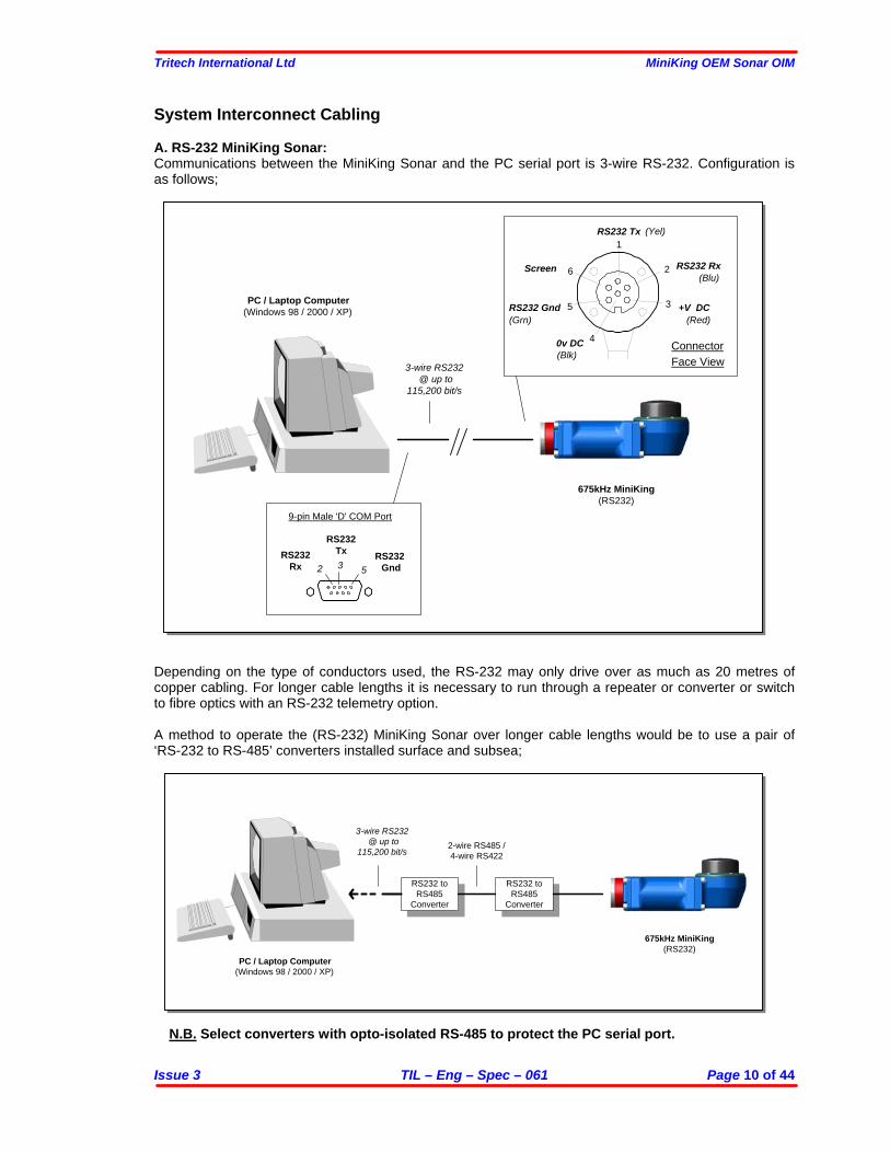
System Interconnect Cabling A. RS-232 MiniKing Sonar: Communications between the MiniKing Sonar and the PC serial port is 3-wire RS-232. Configuration is as follows;
Depending on the type of conductors used, the RS-232 may only drive over as much as 20 metres of copper cabling. For longer cable lengths it is necessary to run through a repeater or converter or switch to fibre optics with an RS-232 telemetry option. A method to operate the (RS-232) MiniKing Sonar over longer cable lengths would be to use a pair of ‘RS-232 to RS-485’ converters installed surface and subsea;
N.B. Select converters with opto-isolated RS-485 to protect the PC serial port.
3-wire RS232 @ up to
115,200 bit/s
PC / Laptop Computer(Windows 98 / 2000 / XP)
675kHz MiniKing(RS232)
9-pin Male 'D' COM Port
2 3 5RS232
Rx
RS232Tx RS232
Gnd
Face ViewConnector
Screen
1
2
3
4
5
6
+V DC
RS232 Tx
RS232 Rx
RS232 Gnd
0v DC
(Yel)
(Grn)
(Blk)
(Red)
(Blu)
3-wire RS232 @ up to
115,200 bit/s
RS232 toRS485
Converter
RS232 toRS485
Converter
2-wire RS485 /4-wire RS422
PC / Laptop Computer(Windows 98 / 2000 / XP)
675kHz MiniKing(RS232)
Tritech International Ltd MiniKing OEM Sonar OIM
Issue 3 TIL – Eng – Spec – 061 Page 11 of 44
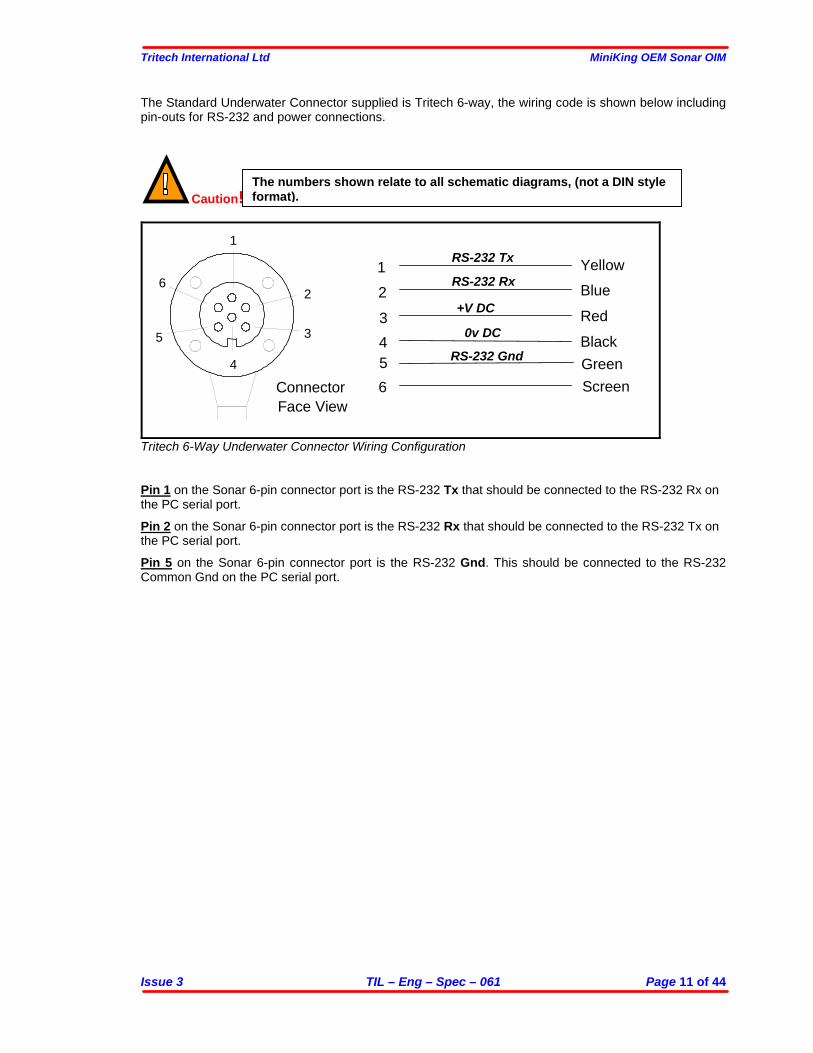
The Standard Underwater Connector supplied is Tritech 6-way, the wiring code is shown below including pin-outs for RS-232 and power connections.
Caution!
Red
Black
Green
Blue
Yellow
Screen
Face View
1
2
3
4
5
6
1
2
3
4
5
6
+V DC
RS-232 Tx
RS-232 Rx
Connector
RS-232 Gnd
0v DC
Tritech 6-Way Underwater Connector Wiring Configuration Pin 1 on the Sonar 6-pin connector port is the RS-232 Tx that should be connected to the RS-232 Rx on the PC serial port. Pin 2 on the Sonar 6-pin connector port is the RS-232 Rx that should be connected to the RS-232 Tx on the PC serial port. Pin 5 on the Sonar 6-pin connector port is the RS-232 Gnd. This should be connected to the RS-232 Common Gnd on the PC serial port.
The numbers shown relate to all schematic diagrams, (not a DIN style format).
Tritech International Ltd MiniKing OEM Sonar OIM
Issue 3 TIL – Eng – Spec – 061 Page 12 of 44
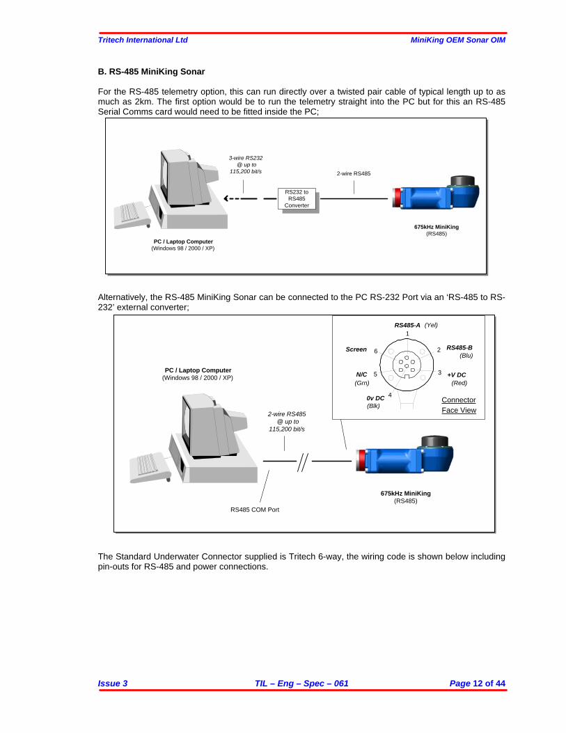
B. RS-485 MiniKing Sonar For the RS-485 telemetry option, this can run directly over a twisted pair cable of typical length up to as much as 2km. The first option would be to run the telemetry straight into the PC but for this an RS-485 Serial Comms card would need to be fitted inside the PC;
Alternatively, the RS-485 MiniKing Sonar can be connected to the PC RS-232 Port via an ‘RS-485 to RS-232’ external converter;
The Standard Underwater Connector supplied is Tritech 6-way, the wiring code is shown below including pin-outs for RS-485 and power connections.
3-wire RS232 @ up to
115,200 bit/s
RS232 toRS485
Converter
2-wire RS485
PC / Laptop Computer(Windows 98 / 2000 / XP)
675kHz MiniKing(RS485)
2-wire RS485 @ up to
115,200 bit/s
PC / Laptop Computer(Windows 98 / 2000 / XP)
675kHz MiniKing(RS485)
RS485 COM Port
Face ViewConnector
Screen
1
2
3
4
5
6
+V DC
RS485-A
RS485-B
N/C
0v DC
(Yel)
(Grn)
(Blk)
(Red)
(Blu)
Tritech International Ltd MiniKing OEM Sonar OIM
Issue 3 TIL – Eng – Spec – 061 Page 13 of 44
Caution!
Red
BlackGreen
Blue
Yellow
ScreenFace View
1
2
3456
1
2
3
4
5
6
+V DC
RS485-A
RS485-B
Connector
N/C
0v DC
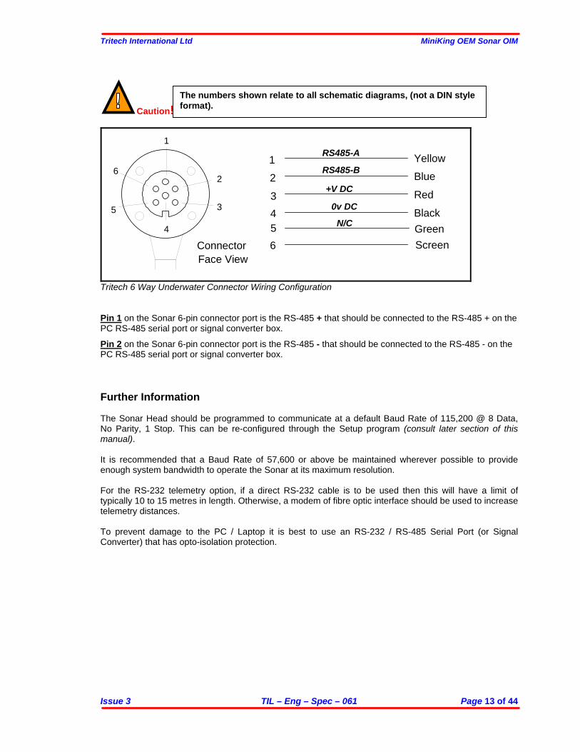
Tritech 6 Way Underwater Connector Wiring Configuration Pin 1 on the Sonar 6-pin connector port is the RS-485 + that should be connected to the RS-485 + on the PC RS-485 serial port or signal converter box. Pin 2 on the Sonar 6-pin connector port is the RS-485 - that should be connected to the RS-485 - on the PC RS-485 serial port or signal converter box. Further Information The Sonar Head should be programmed to communicate at a default Baud Rate of 115,200 @ 8 Data, No Parity, 1 Stop. This can be re-configured through the Setup program (consult later section of this manual). It is recommended that a Baud Rate of 57,600 or above be maintained wherever possible to provide enough system bandwidth to operate the Sonar at its maximum resolution. For the RS-232 telemetry option, if a direct RS-232 cable is to be used then this will have a limit of typically 10 to 15 metres in length. Otherwise, a modem of fibre optic interface should be used to increase telemetry distances. To prevent damage to the PC / Laptop it is best to use an RS-232 / RS-485 Serial Port (or Signal Converter) that has opto-isolation protection.
The numbers shown relate to all schematic diagrams, (not a DIN style format).
Tritech International Ltd MiniKing OEM Sonar OIM
Issue 3 TIL – Eng – Spec – 061 Page 14 of 44
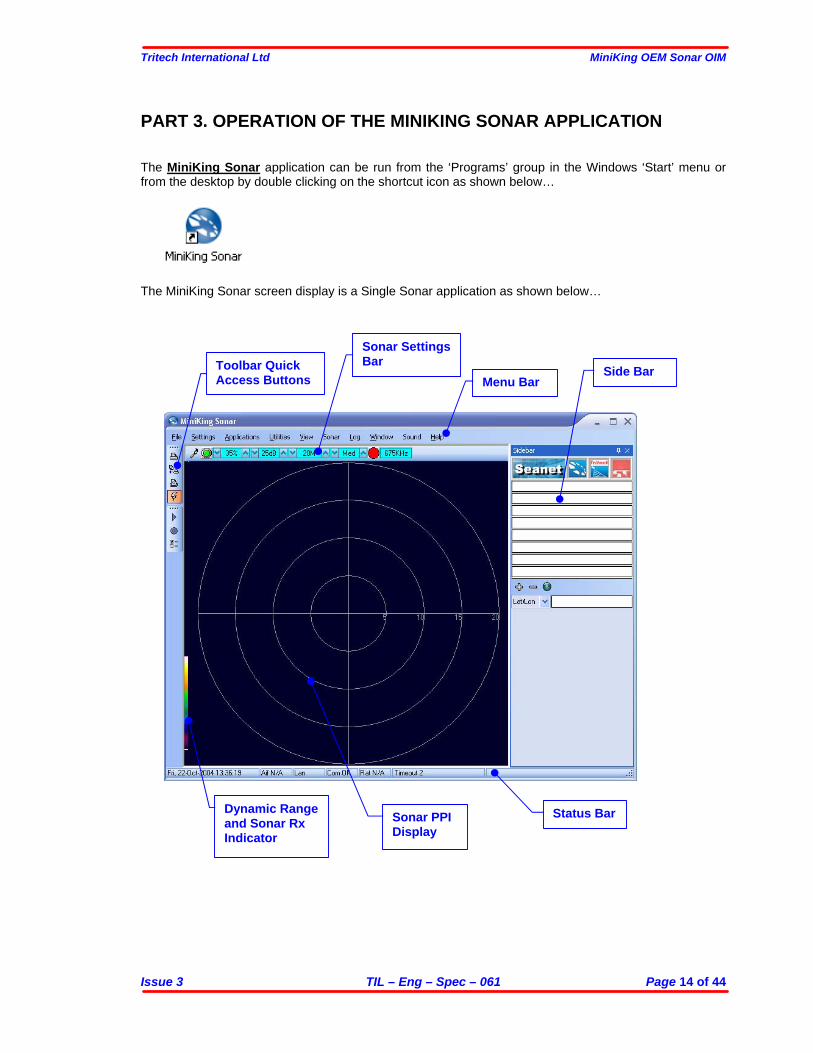
PART 3. OPERATION OF THE MINIKING SONAR APPLICATION The MiniKing Sonar application can be run from the ‘Programs’ group in the Windows ‘Start’ menu or from the desktop by double clicking on the shortcut icon as shown below…
The MiniKing Sonar screen display is a Single Sonar application as shown below…
Menu Bar
Sonar Settings Bar
Status Bar Sonar PPI Display
Side Bar
Dynamic Range and Sonar Rx Indicator
Toolbar Quick Access Buttons
Tritech International Ltd MiniKing OEM Sonar OIM
Issue 3 TIL – Eng – Spec – 061 Page 15 of 44
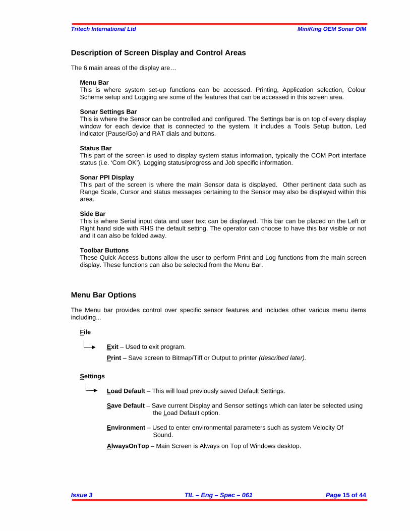
Description of Screen Display and Control Areas The 6 main areas of the display are…
Menu Bar This is where system set-up functions can be accessed. Printing, Application selection, Colour Scheme setup and Logging are some of the features that can be accessed in this screen area.
Sonar Settings Bar This is where the Sensor can be controlled and configured. The Settings bar is on top of every display window for each device that is connected to the system. It includes a Tools Setup button, Led indicator (Pause/Go) and RAT dials and buttons.
Status Bar This part of the screen is used to display system status information, typically the COM Port interface status (i.e. ‘Com OK’), Logging status/progress and Job specific information.
Sonar PPI Display This part of the screen is where the main Sensor data is displayed. Other pertinent data such as Range Scale, Cursor and status messages pertaining to the Sensor may also be displayed within this area. Side Bar This is where Serial input data and user text can be displayed. This bar can be placed on the Left or Right hand side with RHS the default setting. The operator can choose to have this bar visible or not and it can also be folded away. Toolbar Buttons These Quick Access buttons allow the user to perform Print and Log functions from the main screen display. These functions can also be selected from the Menu Bar.
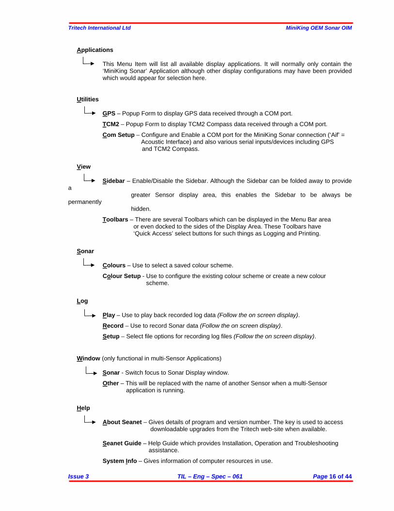
Menu Bar Options The Menu bar provides control over specific sensor features and includes other various menu items including...
File
Exit – Used to exit program.
Print – Save screen to Bitmap/Tiff or Output to printer (described later).
Settings
Load Default – This will load previously saved Default Settings. Save Default – Save current Display and Sensor settings which can later be selected using
the Load Default option. Environment – Used to enter environmental parameters such as system Velocity Of
Sound.
AlwaysOnTop – Main Screen is Always on Top of Windows desktop.
Tritech International Ltd MiniKing OEM Sonar OIM
Issue 3 TIL – Eng – Spec – 061 Page 16 of 44
Applications
This Menu Item will list all available display applications. It will normally only contain the ‘MiniKing Sonar’ Application although other display configurations may have been provided which would appear for selection here.
Utilities
GPS – Popup Form to display GPS data received through a COM port.
TCM2 – Popup Form to display TCM2 Compass data received through a COM port.
Com Setup – Configure and Enable a COM port for the MiniKing Sonar connection (‘Aif’ = Acoustic Interface) and also various serial inputs/devices including GPS
and TCM2 Compass.
View
Sidebar – Enable/Disable the Sidebar. Although the Sidebar can be folded away to provide a
greater Sensor display area, this enables the Sidebar to be always be permanently
hidden.
Toolbars – There are several Toolbars which can be displayed in the Menu Bar area or even docked to the sides of the Display Area. These Toolbars have ‘Quick Access’ select buttons for such things as Logging and Printing.
Sonar
Colours – Use to select a saved colour scheme.
Colour Setup - Use to configure the existing colour scheme or create a new colour scheme.
Log
Play – Use to play back recorded log data (Follow the on screen display).
Record – Use to record Sonar data (Follow the on screen display).
Setup – Select file options for recording log files (Follow the on screen display).
Window (only functional in multi-Sensor Applications)
Sonar - Switch focus to Sonar Display window.
Other – This will be replaced with the name of another Sensor when a multi-Sensor application is running.
Help
About Seanet – Gives details of program and version number. The key is used to access downloadable upgrades from the Tritech web-site when available.
Seanet Guide – Help Guide which provides Installation, Operation and Troubleshooting
assistance.
System Info – Gives information of computer resources in use.
Tritech International Ltd MiniKing OEM Sonar OIM
Issue 3 TIL – Eng – Spec – 061 Page 17 of 44
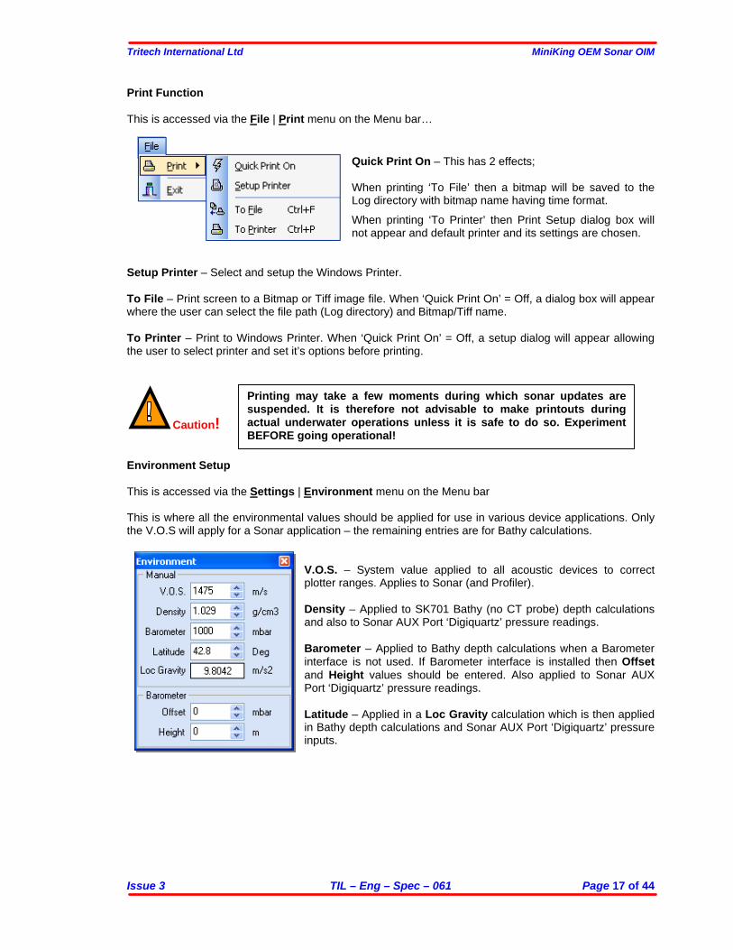
Print Function This is accessed via the File | Print menu on the Menu bar…
Quick Print On – This has 2 effects; When printing ‘To File’ then a bitmap will be saved to the Log directory with bitmap name having time format. When printing ‘To Printer’ then Print Setup dialog box will not appear and default printer and its settings are chosen.
Setup Printer – Select and setup the Windows Printer. To File – Print screen to a Bitmap or Tiff image file. When ‘Quick Print On’ = Off, a dialog box will appear where the user can select the file path (Log directory) and Bitmap/Tiff name. To Printer – Print to Windows Printer. When ‘Quick Print On’ = Off, a setup dialog will appear allowing the user to select printer and set it’s options before printing.
Caution!
Environment Setup This is accessed via the Settings | Environment menu on the Menu bar This is where all the environmental values should be applied for use in various device applications. Only the V.O.S will apply for a Sonar application – the remaining entries are for Bathy calculations.
V.O.S. – System value applied to all acoustic devices to correct plotter ranges. Applies to Sonar (and Profiler). Density – Applied to SK701 Bathy (no CT probe) depth calculations and also to Sonar AUX Port ‘Digiquartz’ pressure readings. Barometer – Applied to Bathy depth calculations when a Barometer interface is not used. If Barometer interface is installed then Offset and Height values should be entered. Also applied to Sonar AUX Port ‘Digiquartz’ pressure readings. Latitude – Applied in a Loc Gravity calculation which is then applied in Bathy depth calculations and Sonar AUX Port ‘Digiquartz’ pressure inputs.
Printing may take a few moments during which sonar updates are suspended. It is therefore not advisable to make printouts during actual underwater operations unless it is safe to do so. Experiment BEFORE going operational!
Tritech International Ltd MiniKing OEM Sonar OIM
Issue 3 TIL – Eng – Spec – 061 Page 18 of 44
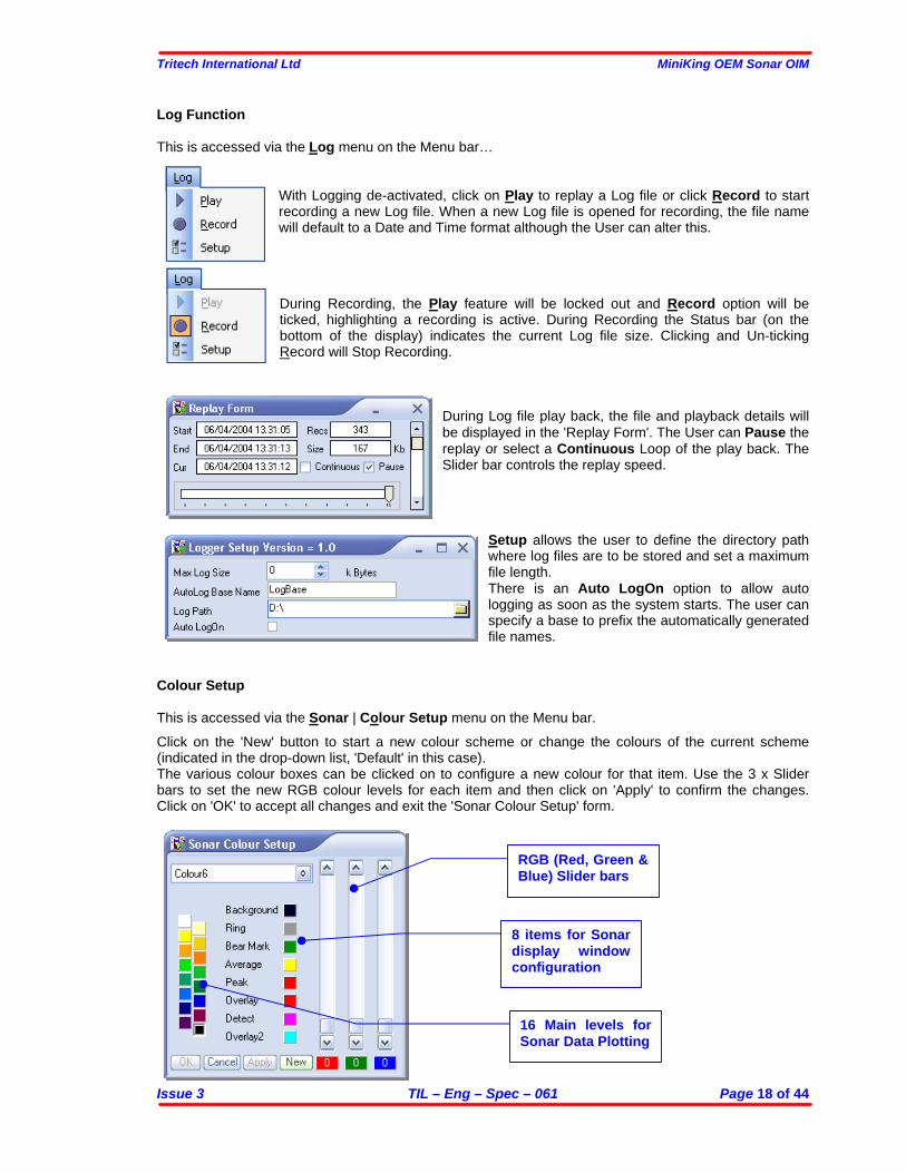
Log Function This is accessed via the Log menu on the Menu bar…
With Logging de-activated, click on Play to replay a Log file or click Record to start recording a new Log file. When a new Log file is opened for recording, the file name will default to a Date and Time format although the User can alter this.
During Recording, the Play feature will be locked out and Record option will be ticked, highlighting a recording is active. During Recording the Status bar (on the bottom of the display) indicates the current Log file size. Clicking and Un-ticking Record will Stop Recording.
During Log file play back, the file and playback details will be displayed in the 'Replay Form'. The User can Pause the replay or select a Continuous Loop of the play back. The Slider bar controls the replay speed.
Setup allows the user to define the directory path where log files are to be stored and set a maximum file length. There is an Auto LogOn option to allow auto logging as soon as the system starts. The user can specify a base to prefix the automatically generated file names.
Colour Setup This is accessed via the Sonar | Colour Setup menu on the Menu bar. Click on the 'New' button to start a new colour scheme or change the colours of the current scheme (indicated in the drop-down list, 'Default' in this case). The various colour boxes can be clicked on to configure a new colour for that item. Use the 3 x Slider bars to set the new RGB colour levels for each item and then click on 'Apply' to confirm the changes. Click on 'OK' to accept all changes and exit the 'Sonar Colour Setup' form.
RGB (Red, Green & Blue) Slider bars
8 items for Sonar display window configuration
16 Main levels for Sonar Data Plotting
Tritech International Ltd MiniKing OEM Sonar OIM
Issue 3 TIL – Eng – Spec – 061 Page 19 of 44
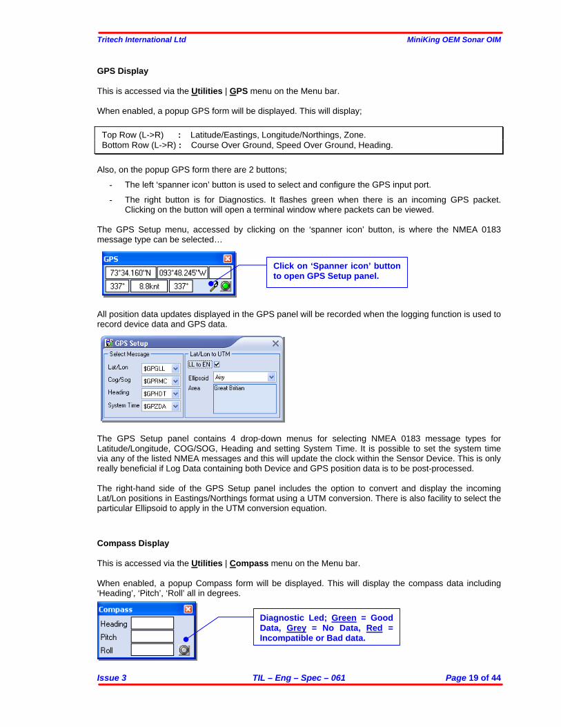
GPS Display This is accessed via the Utilities | GPS menu on the Menu bar. When enabled, a popup GPS form will be displayed. This will display; Top Row (L->R) : Latitude/Eastings, Longitude/Northings, Zone. Bottom Row (L->R) : Course Over Ground, Speed Over Ground, Heading.
Also, on the popup GPS form there are 2 buttons;
- The left ‘spanner icon’ button is used to select and configure the GPS input port. - The right button is for Diagnostics. It flashes green when there is an incoming GPS packet.
Clicking on the button will open a terminal window where packets can be viewed. The GPS Setup menu, accessed by clicking on the ‘spanner icon’ button, is where the NMEA 0183 message type can be selected… All position data updates displayed in the GPS panel will be recorded when the logging function is used to record device data and GPS data. The GPS Setup panel contains 4 drop-down menus for selecting NMEA 0183 message types for Latitude/Longitude, COG/SOG, Heading and setting System Time. It is possible to set the system time via any of the listed NMEA messages and this will update the clock within the Sensor Device. This is only really beneficial if Log Data containing both Device and GPS position data is to be post-processed. The right-hand side of the GPS Setup panel includes the option to convert and display the incoming Lat/Lon positions in Eastings/Northings format using a UTM conversion. There is also facility to select the particular Ellipsoid to apply in the UTM conversion equation.
Compass Display This is accessed via the Utilities | Compass menu on the Menu bar. When enabled, a popup Compass form will be displayed. This will display the compass data including ‘Heading’, ‘Pitch’, ‘Roll’ all in degrees.
Click on ‘Spanner icon’ button to open GPS Setup panel.
Diagnostic Led; Green = Good Data, Grey = No Data, Red = Incompatible or Bad data.
Tritech International Ltd MiniKing OEM Sonar OIM
Issue 3 TIL – Eng – Spec – 061 Page 20 of 44
All data updates displayed in the Compass panel will be recorded when the logging function is used to record device data. Also, on the popup Compass form there is a Diagnostic Led/button. It flashes green when there is an incoming Gyro/Compass packet. Clicking on the button will open a terminal window where packets can be viewed.
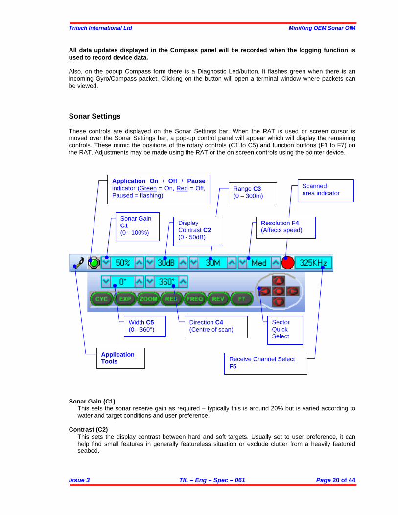
Sonar Settings These controls are displayed on the Sonar Settings bar. When the RAT is used or screen cursor is moved over the Sonar Settings bar, a pop-up control panel will appear which will display the remaining controls. These mimic the positions of the rotary controls (C1 to C5) and function buttons (F1 to F7) on the RAT. Adjustments may be made using the RAT or the on screen controls using the pointer device.
Sonar Gain (C1) This sets the sonar receive gain as required – typically this is around 20% but is varied according to water and target conditions and user preference.
Contrast (C2) This sets the display contrast between hard and soft targets. Usually set to user preference, it can help find small features in generally featureless situation or exclude clutter from a heavily featured seabed.
Application Tools
Application On / Off / Pause indicator (Green = On, Red = Off, Paused = flashing)
Sonar Gain C1 (0 - 100%)
Range C3 (0 – 300m)
Scanned area indicator
Display Contrast C2 (0 - 50dB)
Resolution F4 (Affects speed)
Receive Channel Select F5
Direction C4 (Centre of scan)
Width C5 (0 - 360°)
Sector Quick Select
Tritech International Ltd MiniKing OEM Sonar OIM
Issue 3 TIL – Eng – Spec – 061 Page 21 of 44
Range (C3) This sets the maximum range the sonar will scan. Long ranges are scanned more slowly than short ranges due to the limit imposed by the velocity of sound in water.
Sector Scan Direction (C4) This is used to set the centre of the scanned sector particularly useful to when using a narrow sector width to concentrate on a particular feature. A well positioned, narrow sector will allow faster scan updates than a wide sector.
Sector Scan Width (C5) This sets the width of the scanned sector. Typically this will be adjusted according to the required seabed coverage.
Function button F7 is not currently used. F1, F2 are not applicable in single window applications. CYC (F1) - Cycle Window
This can be used when one of the display windows is maximised using the Expand (F2) button and will cycle between the Sonar display windows. Also use the F1 button to switch focus between the display windows. The optional RAT controller will switch its control to the display that has the focus. Note: clicking on a display with the mouse pointer will also switch focus to that display.
EXP (F2) - Expand Window
This will maximise the current display window that is in focus. Either click on a display window to switch focus to it before expanding, or press the Cycle (F1) button to switch focus to a display window.
ZOOM (F3)
This will toggle the Acoustic Zoom window on/off. This draws a zoom box on the display positioned by the cursor. This control is also toggled via Application Tools - AcoZoom. The Zoom window size and magnification can then be adjusted in ‘Zoom Setup’ in the Application Tools.
RES (F4) – Sonar Resolution
Resolution toggles through 4 preset step sizes for the sonar scanning. Lo resolution gives 1.8° steps, Med = 0.9° steps, Hi = 0.45° steps and Ult = 0.225° steps. Smaller angles give a higher resolution picture but slower scan speeds. Usually a Lo or Med resolution is used for tracking moving targets and Hi or Ult for detailed examination of static targets.
FREQ (F5) - Sonar Frequency This displays the Sonar Transmit frequency. It also toggles between the two receiver channels available on SeaKing Sonar heads.
REV (F5) - Reverse Scan Direction This allows the operator to instantly reverse the scan direction without waiting to reach the end of the scanned sector.
Sector Quick Select This group of 5 buttons allows the user to make a quick selection of a full 360 degree scan or 180 degree forward, back, left or right. The display view is changed automatically and the appropriate sector width and direction set.
Tritech International Ltd MiniKing OEM Sonar OIM
Issue 3 TIL – Eng – Spec – 061 Page 22 of 44
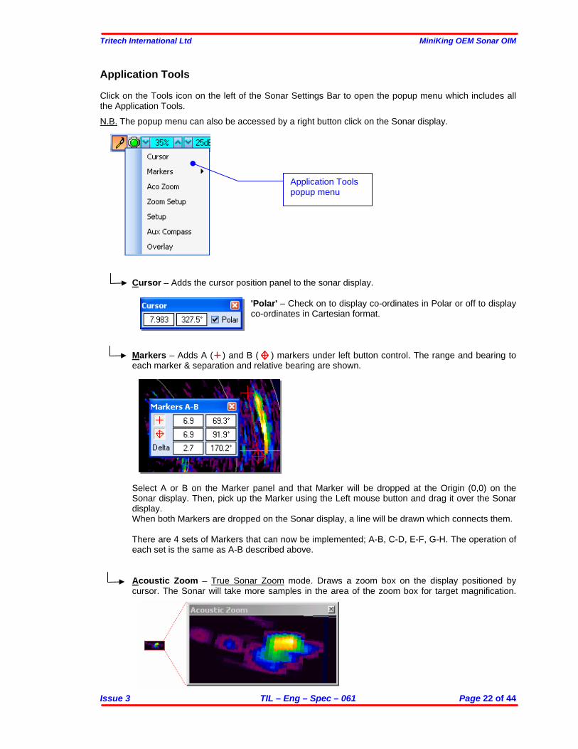
Application Tools
Click on the Tools icon on the left of the Sonar Settings Bar to open the popup menu which includes all the Application Tools. N.B. The popup menu can also be accessed by a right button click on the Sonar display.
Cursor – Adds the cursor position panel to the sonar display. 'Polar' – Check on to display co-ordinates in Polar or off to display
co-ordinates in Cartesian format. Markers – Adds A ( ) and B ( ) markers under left button control. The range and bearing to each marker & separation and relative bearing are shown.
Select A or B on the Marker panel and that Marker will be dropped at the Origin (0,0) on the Sonar display. Then, pick up the Marker using the Left mouse button and drag it over the Sonar display. When both Markers are dropped on the Sonar display, a line will be drawn which connects them. There are 4 sets of Markers that can now be implemented; A-B, C-D, E-F, G-H. The operation of each set is the same as A-B described above.
Acoustic Zoom – True Sonar Zoom mode. Draws a zoom box on the display positioned by cursor. The Sonar will take more samples in the area of the zoom box for target magnification.
Application Tools popup menu
Tritech International Ltd MiniKing OEM Sonar OIM
Issue 3 TIL – Eng – Spec – 061 Page 23 of 44
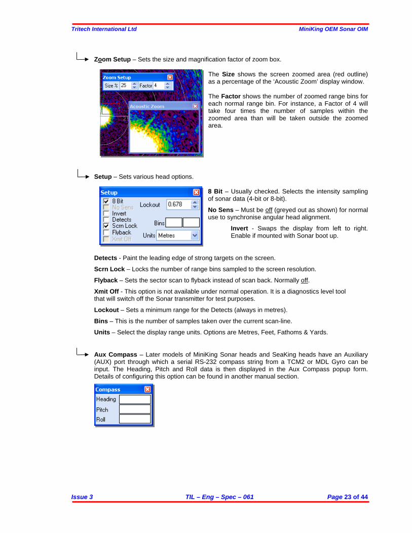
Zoom Setup – Sets the size and magnification factor of zoom box.
The Size shows the screen zoomed area (red outline) as a percentage of the ‘Acoustic Zoom’ display window. The Factor shows the number of zoomed range bins for each normal range bin. For instance, a Factor of 4 will take four times the number of samples within the zoomed area than will be taken outside the zoomed area.
Setup – Sets various head options.
8 Bit – Usually checked. Selects the intensity sampling of sonar data (4-bit or 8-bit). No Sens – Must be off (greyed out as shown) for normal use to synchronise angular head alignment.
Invert - Swaps the display from left to right. Enable if mounted with Sonar boot up.
Detects - Paint the leading edge of strong targets on the screen. Scrn Lock – Locks the number of range bins sampled to the screen resolution. Flyback – Sets the sector scan to flyback instead of scan back. Normally off. Xmit Off - This option is not available under normal operation. It is a diagnostics level tool that will switch off the Sonar transmitter for test purposes. Lockout – Sets a minimum range for the Detects (always in metres). Bins – This is the number of samples taken over the current scan-line. Units – Select the display range units. Options are Metres, Feet, Fathoms & Yards. Aux Compass – Later models of MiniKing Sonar heads and SeaKing heads have an Auxiliary (AUX) port through which a serial RS-232 compass string from a TCM2 or MDL Gyro can be input. The Heading, Pitch and Roll data is then displayed in the Aux Compass popup form. Details of configuring this option can be found in another manual section.
Tritech International Ltd MiniKing OEM Sonar OIM
Issue 3 TIL – Eng – Spec – 061 Page 24 of 44
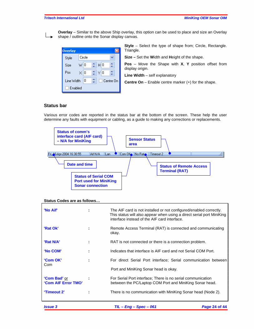
Date and time
Status of comm’s interface card (AIF card) – N/A for MiniKing
Status of Remote Access Terminal (RAT)
Status of Serial COM Port used for MiniKing Sonar connection
Sensor Status area
Overlay – Similar to the above Ship overlay, this option can be used to place and size an Overlay shape / outline onto the Sonar display canvas.
Style – Select the type of shape from; Circle, Rectangle. Triangle. Size – Set the Width and Height of the shape. Pos – Move the Shape with X, Y position offset from display origin. Line Width – self explanatory Centre On – Enable centre marker (+) for the shape.
Status bar Various error codes are reported in the status bar at the bottom of the screen. These help the user determine any faults with equipment or cabling, as a guide to making any corrections or replacements.
Status Codes are as follows…
'No Aif' : The AIF card is not installed or not configured/enabled correctly. This status will also appear when using a direct serial port MiniKing
interface instead of the AIF card interface. 'Rat Ok' : Remote Access Terminal (RAT) is connected and communicating
okay. 'Rat N/A' : RAT is not connected or there is a connection problem. ‘No COM’ : Indicates that interface is AIF card and not Serial COM Port. ‘Com OK’ : For direct Serial Port interface; Serial communication between Com
Port and MiniKing Sonar head is okay. ‘Com Bad’ or : For Serial Port interface; There is no serial communication ‘Com AIF Error TMO’ between the PC/Laptop COM Port and MiniKing Sonar head. ‘Timeout 2’ : There is no communication with MiniKing Sonar head (Node 2).
Tritech International Ltd MiniKing OEM Sonar OIM
Issue 3 TIL – Eng – Spec – 061 Page 25 of 44
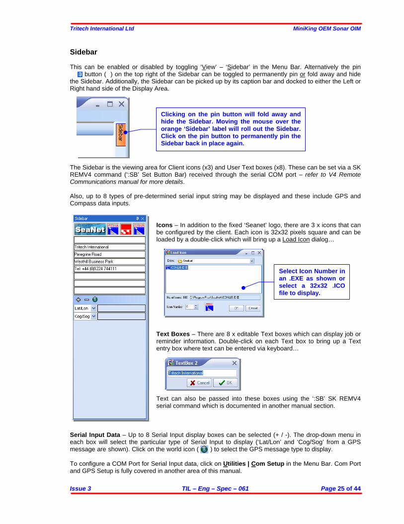
Sidebar This can be enabled or disabled by toggling ‘View’ – ‘Sidebar’ in the Menu Bar. Alternatively the pin
button ( ) on the top right of the Sidebar can be toggled to permanently pin or fold away and hide the Sidebar. Additionally, the Sidebar can be picked up by its caption bar and docked to either the Left or Right hand side of the Display Area. The Sidebar is the viewing area for Client icons (x3) and User Text boxes (x8). These can be set via a SK REMV4 command (‘:SB’ Set Button Bar) received through the serial COM port – refer to V4 Remote Communications manual for more details. Also, up to 8 types of pre-determined serial input string may be displayed and these include GPS and Compass data inputs.
Icons – In addition to the fixed ‘Seanet’ logo, there are 3 x icons that can be configured by the client. Each icon is 32x32 pixels square and can be loaded by a double-click which will bring up a Load Icon dialog… Text Boxes – There are 8 x editable Text boxes which can display job or reminder information. Double-click on each Text box to bring up a Text entry box where text can be entered via keyboard…
Text can also be passed into these boxes using the ‘:SB’ SK REMV4 serial command which is documented in another manual section.
Serial Input Data – Up to 8 Serial Input display boxes can be selected (+ / -). The drop-down menu in each box will select the particular type of Serial Input to display (‘Lat/Lon’ and ‘Cog/Sog’ from a GPS message are shown). Click on the world icon ( ) to select the GPS message type to display. To configure a COM Port for Serial Input data, click on Utilities | Com Setup in the Menu Bar. Com Port and GPS Setup is fully covered in another area of this manual.
Select Icon Number in an .EXE as shown or select a 32x32 .ICO file to display.
Clicking on the pin button will fold away and hide the Sidebar. Moving the mouse over the orange ‘Sidebar’ label will roll out the Sidebar. Click on the pin button to permanently pin the Sidebar back in place again.
Tritech International Ltd MiniKing OEM Sonar OIM
Issue 3 TIL – Eng – Spec – 061 Page 26 of 44
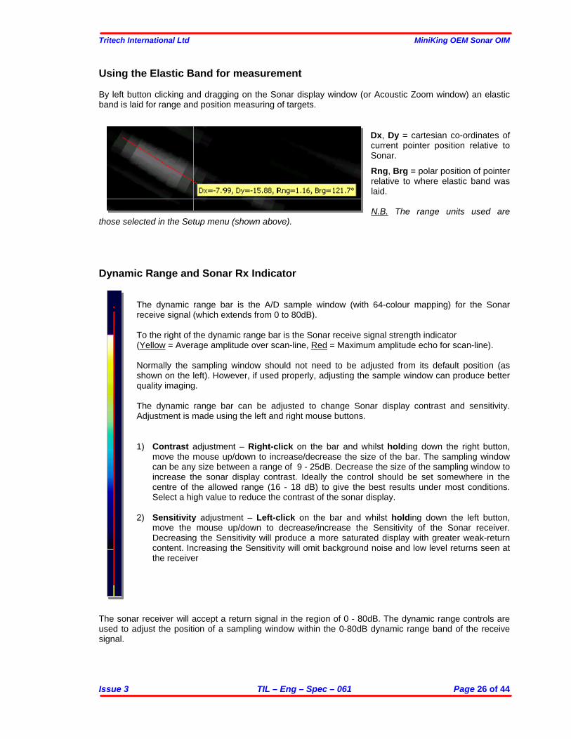
Using the Elastic Band for measurement By left button clicking and dragging on the Sonar display window (or Acoustic Zoom window) an elastic band is laid for range and position measuring of targets.
Dx, Dy = cartesian co-ordinates of current pointer position relative to Sonar. Rng, Brg = polar position of pointer relative to where elastic band was laid. N.B. The range units used are
those selected in the Setup menu (shown above). Dynamic Range and Sonar Rx Indicator
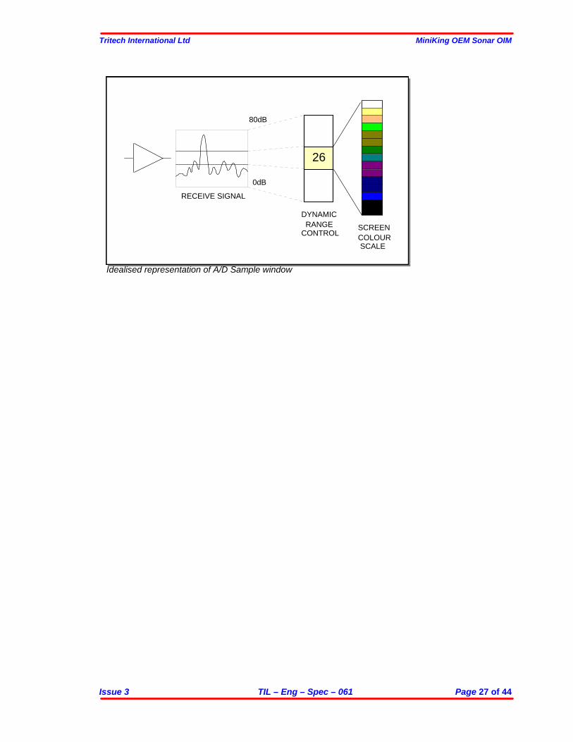
The dynamic range bar is the A/D sample window (with 64-colour mapping) for the Sonar receive signal (which extends from 0 to 80dB). To the right of the dynamic range bar is the Sonar receive signal strength indicator (Yellow = Average amplitude over scan-line, Red = Maximum amplitude echo for scan-line). Normally the sampling window should not need to be adjusted from its default position (as shown on the left). However, if used properly, adjusting the sample window can produce better quality imaging. The dynamic range bar can be adjusted to change Sonar display contrast and sensitivity. Adjustment is made using the left and right mouse buttons. 1) Contrast adjustment – Right-click on the bar and whilst holding down the right button,
move the mouse up/down to increase/decrease the size of the bar. The sampling window can be any size between a range of 9 - 25dB. Decrease the size of the sampling window to increase the sonar display contrast. Ideally the control should be set somewhere in the centre of the allowed range (16 - 18 dB) to give the best results under most conditions. Select a high value to reduce the contrast of the sonar display.
2) Sensitivity adjustment – Left-click on the bar and whilst holding down the left button,
move the mouse up/down to decrease/increase the Sensitivity of the Sonar receiver. Decreasing the Sensitivity will produce a more saturated display with greater weak-return content. Increasing the Sensitivity will omit background noise and low level returns seen at the receiver
The sonar receiver will accept a return signal in the region of 0 - 80dB. The dynamic range controls are used to adjust the position of a sampling window within the 0-80dB dynamic range band of the receive signal.
Tritech International Ltd MiniKing OEM Sonar OIM
Issue 3 TIL – Eng – Spec – 061 Page 27 of 44
Idealised representation of A/D Sample window
80dB
0dB
26
DYNAMIC RANGECONTROL
SCREENCOLOUR SCALE
RECEIVE SIGNAL
Tritech International Ltd MiniKing OEM Sonar OIM
Issue 3 TIL – Eng – Spec – 061 Page 28 of 44
MAINTENANCE MiniKing Head maintenance Wash down with fresh water each time a unit is recovered from the water, paying particular attention to the boot and connector areas. Although units are designed for a wide temperature range it is best to avoid temperature extremes for long periods and protect units from bright sunlight. Repairs are by major unit change out which may involve reprogramming a head. In these cases instructions will be supplied. It is recommended that usage logs are maintained and that the heads are returned to vendor at 4000-hour intervals for routine inspection/replacement of slip rings, compensation oil and O ring seals Underwater cables are not normally within the scope of supply, but will also require regular inspection. Cables
The cables are high quality with low halogen jackets which should provide long service life without problems. Care should be taken to ensure that they are properly sited during installation to avoid movement and fatigue, but otherwise no maintenance is required. Computer
The PC / Laptop computer should be loaded with a standard version of Windows 98 / 2000 or XP. If for any reason it is necessary to reload the Sonar system this should be done using the CD supplied. Follow the setup dialog during installation.
The Sonar software can be reloaded as follows… 1) Insert the Sonar CD into the CD ROM drive. 2) Browse the CD ROM drive and run Setup.exe from the root. Follow the on screen directions. This will
automatically install the Sonar software to the Program Files directory on the C:\ drive. 3) The Registry retains any user-configured changes. When Setup.exe is run the registry will be set
back to a factory default setting. 4) Shortcut(s) will automatically be created on the Windows Desktop to run the Sonar software and any
utility programs that may have been supplied. To Remove the Sonar software, use “Settings\ControlPanel” from the Windows Start Menu… 1) Run Add/Remove Programs and select ‘MiniKing Sonar’. 2) Follow the on screen directions and choose Uninstall from the options. 3) On completion all the above installation will be removed, including the Registry settings and Desktop
Shortcuts 4) The Screen resolution should be set to maximum 1024x768 at either 16-bit or 32-bit colours.
Tritech International Ltd MiniKing OEM Sonar OIM
Issue 3 TIL – Eng – Spec – 061 Page 29 of 44
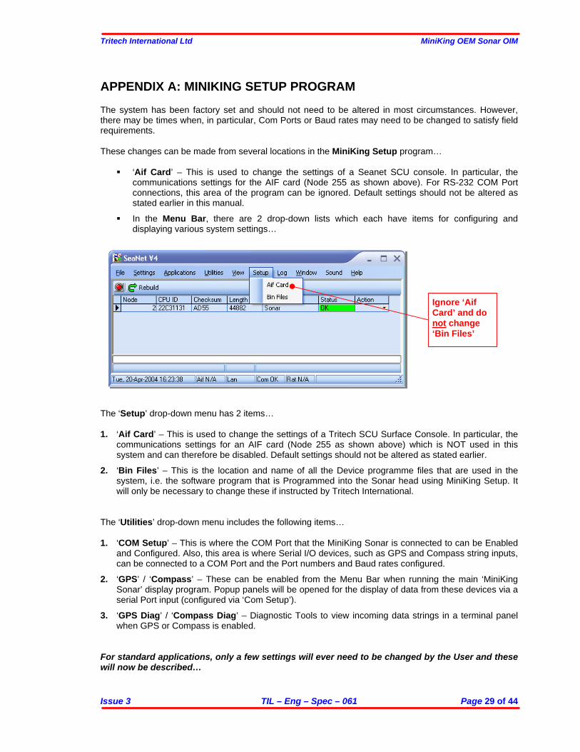
APPENDIX A: MINIKING SETUP PROGRAM The system has been factory set and should not need to be altered in most circumstances. However, there may be times when, in particular, Com Ports or Baud rates may need to be changed to satisfy field requirements. These changes can be made from several locations in the MiniKing Setup program…
‘Aif Card’ – This is used to change the settings of a Seanet SCU console. In particular, the communications settings for the AIF card (Node 255 as shown above). For RS-232 COM Port connections, this area of the program can be ignored. Default settings should not be altered as stated earlier in this manual.
In the Menu Bar, there are 2 drop-down lists which each have items for configuring and
displaying various system settings…
The ‘Setup’ drop-down menu has 2 items… 1. ‘Aif Card’ – This is used to change the settings of a Tritech SCU Surface Console. In particular, the
communications settings for an AIF card (Node 255 as shown above) which is NOT used in this system and can therefore be disabled. Default settings should not be altered as stated earlier.
2. ‘Bin Files’ – This is the location and name of all the Device programme files that are used in the
system, i.e. the software program that is Programmed into the Sonar head using MiniKing Setup. It will only be necessary to change these if instructed by Tritech International.
The ‘Utilities’ drop-down menu includes the following items… 1. ‘COM Setup’ – This is where the COM Port that the MiniKing Sonar is connected to can be Enabled
and Configured. Also, this area is where Serial I/O devices, such as GPS and Compass string inputs, can be connected to a COM Port and the Port numbers and Baud rates configured.
2. ‘GPS’ / ‘Compass’ – These can be enabled from the Menu Bar when running the main ‘MiniKing
Sonar’ display program. Popup panels will be opened for the display of data from these devices via a serial Port input (configured via ‘Com Setup’).
3. ‘GPS Diag’ / ‘Compass Diag’ – Diagnostic Tools to view incoming data strings in a terminal panel
when GPS or Compass is enabled. For standard applications, only a few settings will ever need to be changed by the User and these will now be described…
Ignore ‘Aif Card’ and do not change ‘Bin Files’
Tritech International Ltd MiniKing OEM Sonar OIM
Issue 3 TIL – Eng – Spec – 061 Page 30 of 44
Configuring Com Port and Baud Rates Changing the telemetry Baud Rate from the default 115.2k should only ever be necessary to communicate over a longer RS-232 serial cable (i.e. >10metres in length installed between the PC and the MiniKing Sonar head or signal converter) or over a modem system that can only handle lower rates. In this event, the Baud Rate should be kept as high as possible to give enough system bandwidth for the Sonar head(s) to operate at full speed and resolution. The first step is to communicate with the Sonar head which involves setting the COM Port settings within the Setup program to match the MiniKing Sonar baud rate and COM port connection. It may be necessary to use a short serial cable to first communicate with and re-program the MiniKing Sonar before it is then installed on the longer cable or modem system.
First change the COM Port Baud Rate to match current Sonar settings…
N.B. The Setup program default will be COM1 @ 115.2K which matches the ‘MiniKing Sonar’ display software defaults.
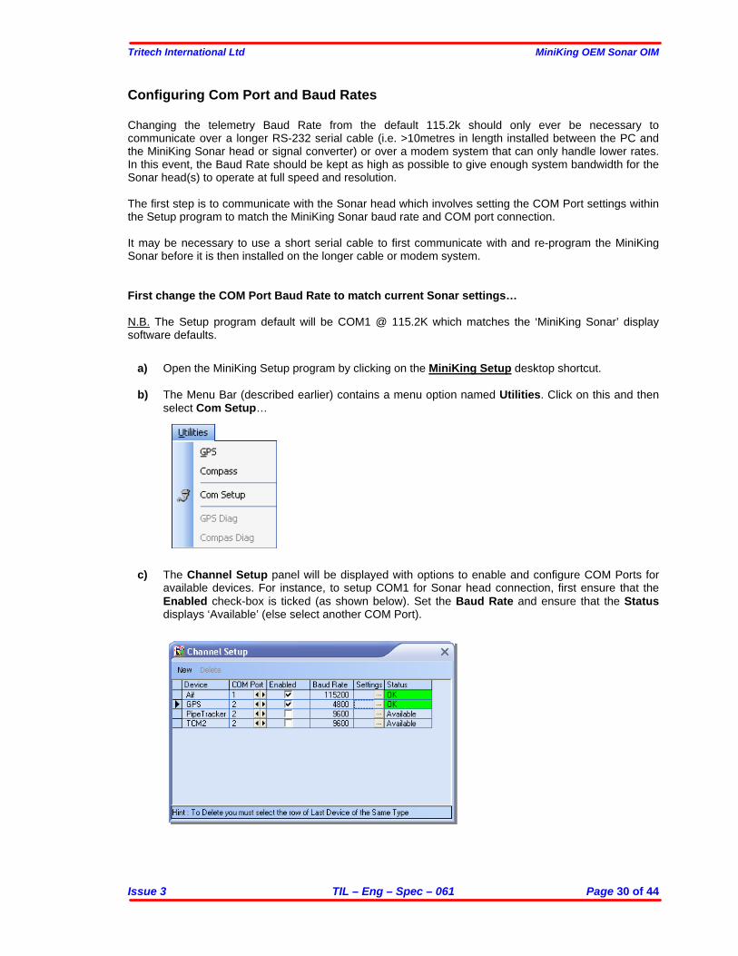
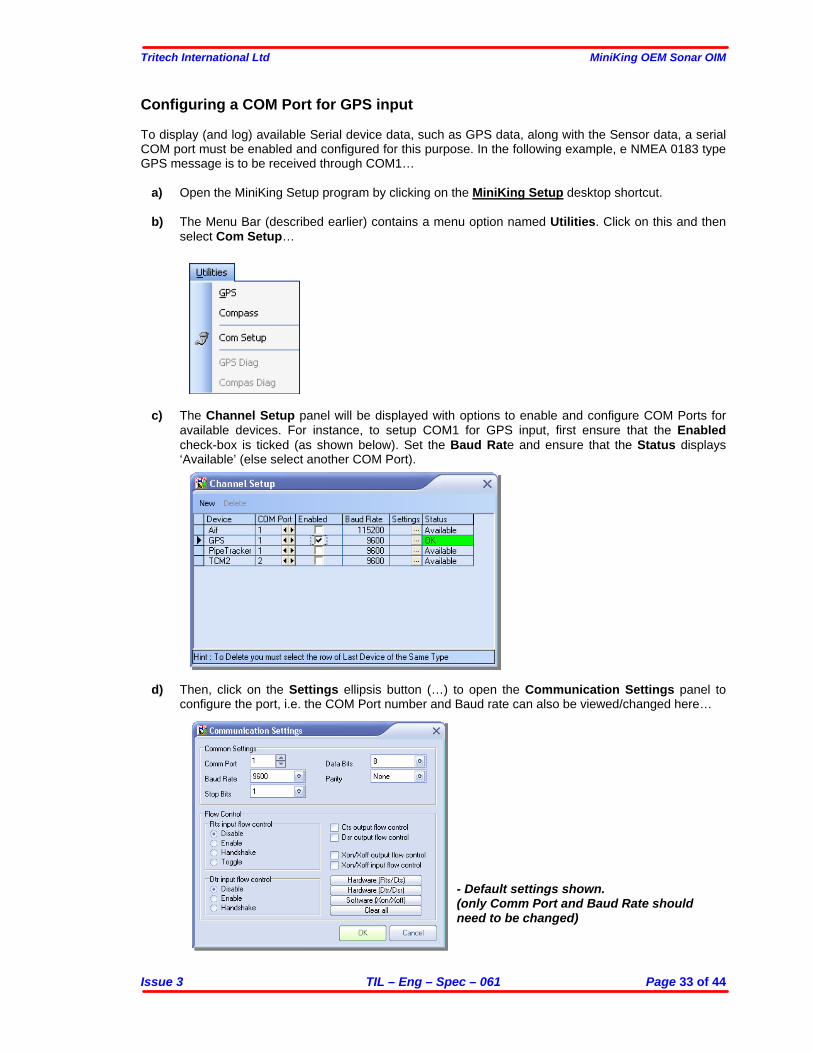
a) Open the MiniKing Setup program by clicking on the MiniKing Setup desktop shortcut. b) The Menu Bar (described earlier) contains a menu option named Utilities. Click on this and then
select Com Setup…
c) The Channel Setup panel will be displayed with options to enable and configure COM Ports for available devices. For instance, to setup COM1 for Sonar head connection, first ensure that the Enabled check-box is ticked (as shown below). Set the Baud Rate and ensure that the Status displays ‘Available’ (else select another COM Port).
Tritech International Ltd MiniKing OEM Sonar OIM
Issue 3 TIL – Eng – Spec – 061 Page 31 of 44
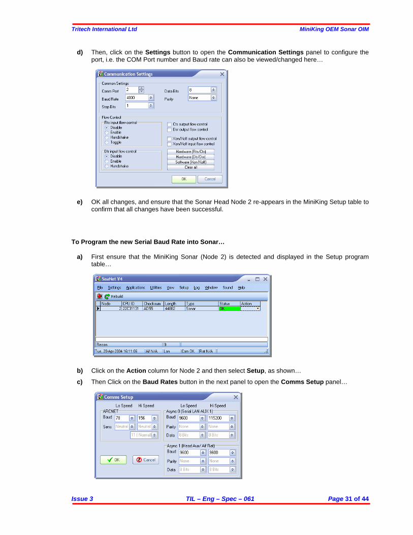
d) Then, click on the Settings button to open the Communication Settings panel to configure the port, i.e. the COM Port number and Baud rate can also be viewed/changed here…
e) OK all changes, and ensure that the Sonar Head Node 2 re-appears in the MiniKing Setup table to confirm that all changes have been successful.
To Program the new Serial Baud Rate into Sonar…
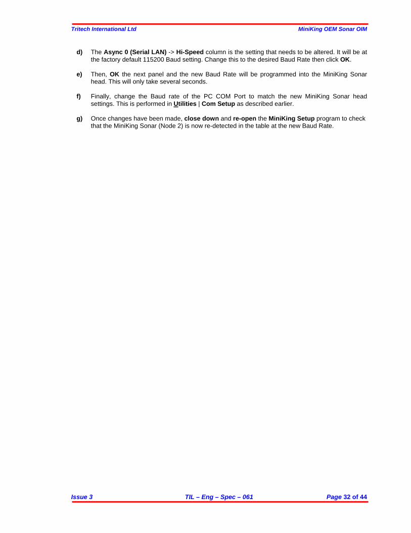
a) First ensure that the MiniKing Sonar (Node 2) is detected and displayed in the Setup program table…
b) Click on the Action column for Node 2 and then select Setup, as shown…
c) Then Click on the Baud Rates button in the next panel to open the Comms Setup panel…
Tritech International Ltd MiniKing OEM Sonar OIM
Issue 3 TIL – Eng – Spec – 061 Page 32 of 44
d) The Async 0 (Serial LAN) -> Hi-Speed column is the setting that needs to be altered. It will be at the factory default 115200 Baud setting. Change this to the desired Baud Rate then click OK.
e) Then, OK the next panel and the new Baud Rate will be programmed into the MiniKing Sonar
head. This will only take several seconds.
f) Finally, change the Baud rate of the PC COM Port to match the new MiniKing Sonar head settings. This is performed in Utilities | Com Setup as described earlier.
g) Once changes have been made, close down and re-open the MiniKing Setup program to check
that the MiniKing Sonar (Node 2) is now re-detected in the table at the new Baud Rate.
Tritech International Ltd MiniKing OEM Sonar OIM
Issue 3 TIL – Eng – Spec – 061 Page 33 of 44
Configuring a COM Port for GPS input To display (and log) available Serial device data, such as GPS data, along with the Sensor data, a serial COM port must be enabled and configured for this purpose. In the following example, e NMEA 0183 type GPS message is to be received through COM1…
a) Open the MiniKing Setup program by clicking on the MiniKing Setup desktop shortcut. b) The Menu Bar (described earlier) contains a menu option named Utilities. Click on this and then
select Com Setup…
c) The Channel Setup panel will be displayed with options to enable and configure COM Ports for available devices. For instance, to setup COM1 for GPS input, first ensure that the Enabled check-box is ticked (as shown below). Set the Baud Rate and ensure that the Status displays ‘Available’ (else select another COM Port).
d) Then, click on the Settings ellipsis button (…) to open the Communication Settings panel to
configure the port, i.e. the COM Port number and Baud rate can also be viewed/changed here…
- Default settings shown. (only Comm Port and Baud Rate should need to be changed)
Tritech International Ltd MiniKing OEM Sonar OIM
Issue 3 TIL – Eng – Spec – 061 Page 34 of 44
APPENDIX B: MINIKING AUX PORT Introduction It is possible to configure the ‘Aux’ port on the MiniKing Sonar for input of RS-232 serial data from a free-running serial device such as Tritech Altimeter, MDL/TCM2 Compass or Series-8000 Digiquartz Pressure Sensor. It may be possible to power the Sensor from the Sonar Aux Port but first check that the Power ranges are the same. There are 2 MiniKing configurations available:-
1) The DC power that is applied to the MiniKing Sonar ‘Main’ port is linked directly through to the Aux port.
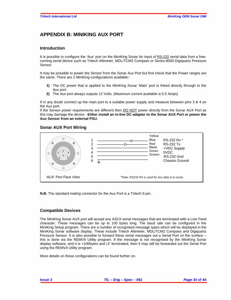
2) The Aux port always outputs 12 Volts. (Maximum current available is 0.5 Amps) If in any doubt connect up the main port to a suitable power supply and measure between pins 3 & 4 on the Aux port. If the Sensor power requirements are different then DO NOT power directly from the Sonar AUX Port as this may damage the device - Either install an in-line DC adapter to the Sonar AUX Port or power the Aux Sensor from an external PSU. Sonar AUX Port Wiring
1 RS-232 Rx * 2 RS-232 Tx 3 +VDC Supply 4 0VDC 5 RS-232 Gnd 6 Chassis Ground
‘AUX’ Port Face View *Note: RS232 RX is used for Aux data in to sonar. N.B. The standard mating connector for the Aux Port is a Tritech 6-pin. Compatible Devices The MiniKing Sonar AUX port will accept any ASCII serial messages that are terminated with a Line Feed character. These messages can be up to 100 bytes long. The baud rate can be configured in the MiniKing Setup program. There are a number of recognised message types which will be displayed in the MiniKing Sonar software display. These include Tritech Altimeter, MDL/TCM2 Compass and Digiquartz Pressure Sensor. It is also possible to forward these serial messages out a Serial Port on the surface – this is done via the REMV4 Utility program. If the message is not recognised by the MiniKing Sonar display software, and it is <100bytes and LF terminated, then it may still be forwarded out the Serial Port using the REMV4 Utility program. More details on these configurations can be found further on.
12
34
5
6
YellowBlue
BlackGreenScreen
Red
Tritech International Ltd MiniKing OEM Sonar OIM
Issue 3 TIL – Eng – Spec – 061 Page 35 of 44
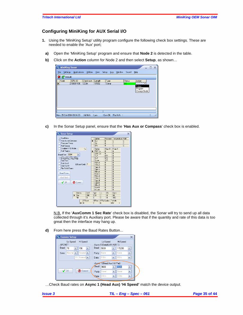
Configuring MiniKing for AUX Serial I/O 1. Using the 'MiniKing Setup' utility program configure the following check box settings. These are
needed to enable the 'Aux' port;
a) Open the ‘MiniKing Setup’ program and ensure that Node 2 is detected in the table.
b) Click on the Action column for Node 2 and then select Setup, as shown…
c) In the Sonar Setup panel, ensure that the ‘Has Aux or Compass’ check box is enabled.
N.B. If the ‘AuxComm 1 Sec Rate’ check box is disabled, the Sonar will try to send up all data collected through it’s Auxiliary port. Please be aware that if the quantity and rate of this data is too great then the interface may hang up.
d) From here press the Baud Rates Button...
…Check Baud rates on Async 1 (Head Aux) ‘Hi Speed’ match the device output.
Tritech International Ltd MiniKing OEM Sonar OIM
Issue 3 TIL – Eng – Spec – 061 Page 36 of 44
SOFTWARE SETTINGS Once the MiniKing Sonar head has been correctly configured with the AUX device connected, power up the system and run the main ‘MiniKing Sonar’ application software. N.B. Ensure that the MiniKing Setup program is closed down first. Then, when running a Sonar application and recognised serial Aux data is received via the Sonar Aux Port, this data will be displayed on the Settings Bar on in a Popup box which is dependant on the data type. The data may also be forwarded out the Serial Port using the REMV4 Utility program. If the serial Aux data is unrecognised then it may only be forwarded out the Serial Port – Note: the message must be under 100 bytes and be Line Feed terminated.
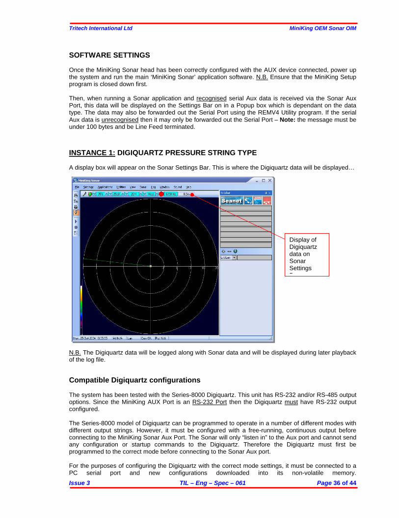
INSTANCE 1: DIGIQUARTZ PRESSURE STRING TYPE A display box will appear on the Sonar Settings Bar. This is where the Digiquartz data will be displayed…
N.B. The Digiquartz data will be logged along with Sonar data and will be displayed during later playback of the log file.
Compatible Digiquartz configurations The system has been tested with the Series-8000 Digiquartz. This unit has RS-232 and/or RS-485 output options. Since the MiniKing AUX Port is an RS-232 Port then the Digiquartz must have RS-232 output configured. The Series-8000 model of Digiquartz can be programmed to operate in a number of different modes with different output strings. However, it must be configured with a free-running, continuous output before connecting to the MiniKing Sonar Aux Port. The Sonar will only “listen in” to the Aux port and cannot send any configuration or startup commands to the Digiquartz. Therefore the Digiquartz must first be programmed to the correct mode before connecting to the Sonar Aux port. For the purposes of configuring the Digiquartz with the correct mode settings, it must be connected to a PC serial port and new configurations downloaded into its non-volatile memory.
Display of Digiquartz data on Sonar Settings B
Tritech International Ltd MiniKing OEM Sonar OIM
Issue 3 TIL – Eng – Spec – 061 Page 37 of 44
The manufacturer (Paroscientific) provides a Windows based program for checking and downloading configurations and modes into the Digiquartz unit. The Sonar Aux port will accept any serial messages that are terminated with a Line Feed character. These messages can be up to 100 bytes long. However, at the surface, the MiniKing Sonar program must be able to identify what the units are for the Digiquartz data it is being sent. The MiniKing Sonar display program will only interpret pressure data that is sent from the Digiquartz in either Psi or Bar. Again, these data messages must have unit labels attached – the correct output mode should be programmed into the unit using the manufacturers Windows based program. Once pressure data has been recognised, it will be applied to a depth calculation and the resultant depth value in metres will be displayed on the Sonar Settings Bar. The depth calculation will use a Density and Barometer value that has been entered through Settings | Environment on the Menu bar. If the local Latitude is known then this should also be entered to correct the Local Gravity constant that is also applied in the following depth equation…
Depth = [ ( ( p - (a * 0.014696) ) * 0.70307) / d] * [Gcal / Glocal]
where;
Depth is calculated depth in metres. p is Absolute pressure measured by Digiquartz in PSI. a is Surface Barometric pressure in mbar. d is Water Density in g/cm3.
0.014696 is Bar to Psi conversion factor 0.70307 is Psi to Metres conversion factor
Gcal is 9.80665 m/sec2 (see below). Glocal is Specific Gravity of seawater (Latitude dependant - entered into Surface software menu) - see below…
Specific Gravity (Glocal) Equation
All Tritech supplied Digiquartz Pressure Sensors are calibrated using a deadweight tester in a location where the Gravity value is 9.80665 m/sec2.
Computed Depth calculations take into account the Gravity of the operating location, which is specified as a latitude. The local gravity value used in the Depth calculations is computed from the following formula (Intl. Assoc of Geodesy, Sp.Pub.Bull. geodesy 1970):
Glocal = Ge * ( 1 + B1* sin^2(lat) + B2* sin^2(2*lat) ) where; Ge = 9.7803184 m/sec2 B1 = 0.0053024 B2 = 0.0000059 lat = local Latitude
Tritech International Ltd MiniKing OEM Sonar OIM
Issue 3 TIL – Eng – Spec – 061 Page 38 of 44
Output Modes The Series-8000 Digiquartz manual should be consulted for full details of the different modes it can be programmed with. Only pressure data (output in Bar or Psi) are supported by the MiniKing Sonar display program. Here is a list of the modes that should be programmed to operate with the Sonar Aux port interface…
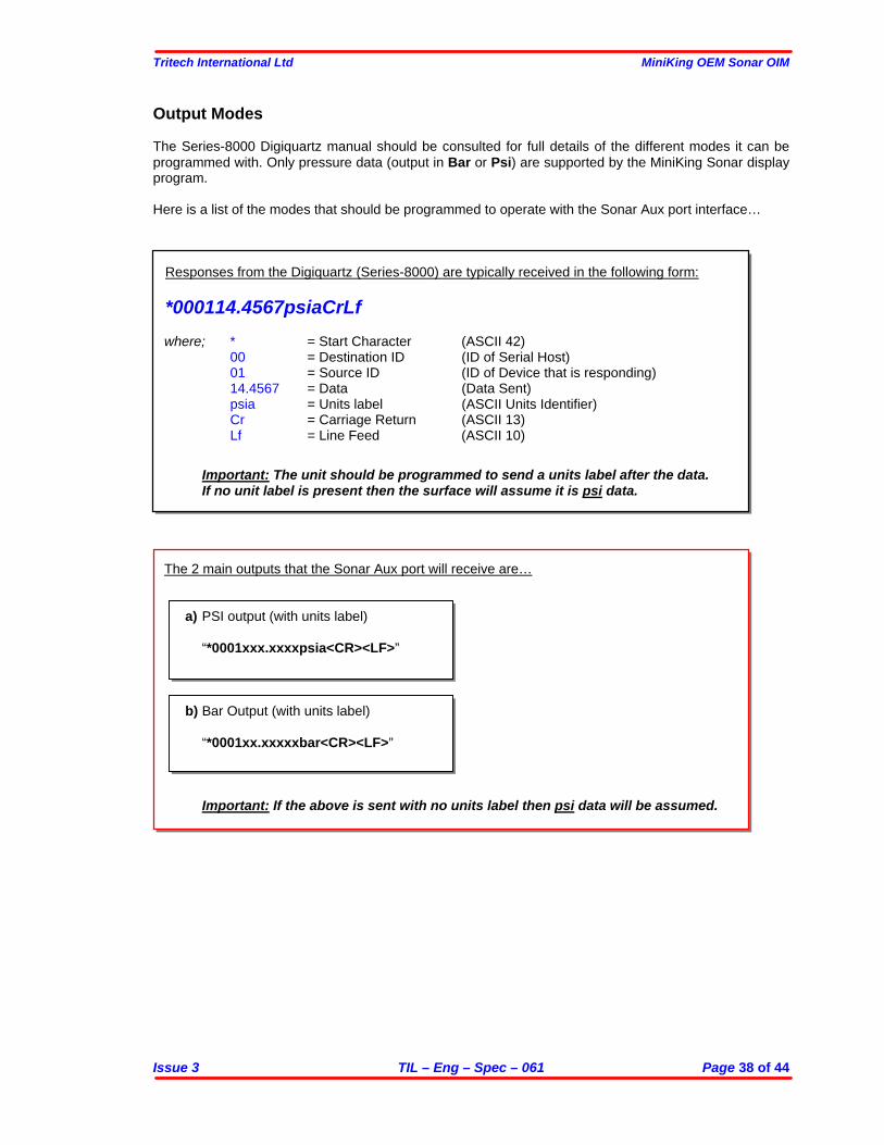
Responses from the Digiquartz (Series-8000) are typically received in the following form:
*000114.4567psiaCrLf where; * = Start Character (ASCII 42) 00 = Destination ID (ID of Serial Host) 01 = Source ID (ID of Device that is responding) 14.4567 = Data (Data Sent) psia = Units label (ASCII Units Identifier)
Cr = Carriage Return (ASCII 13) Lf = Line Feed (ASCII 10)
Important: The unit should be programmed to send a units label after the data. If no unit label is present then the surface will assume it is psi data.
The 2 main outputs that the Sonar Aux port will receive are…
a) PSI output (with units label)
“*0001xxx.xxxxpsia<CR><LF>”
b) Bar Output (with units label)
“*0001xx.xxxxxbar<CR><LF>”
Important: If the above is sent with no units label then psi data will be assumed.
Tritech International Ltd MiniKing OEM Sonar OIM
Issue 3 TIL – Eng – Spec – 061 Page 39 of 44
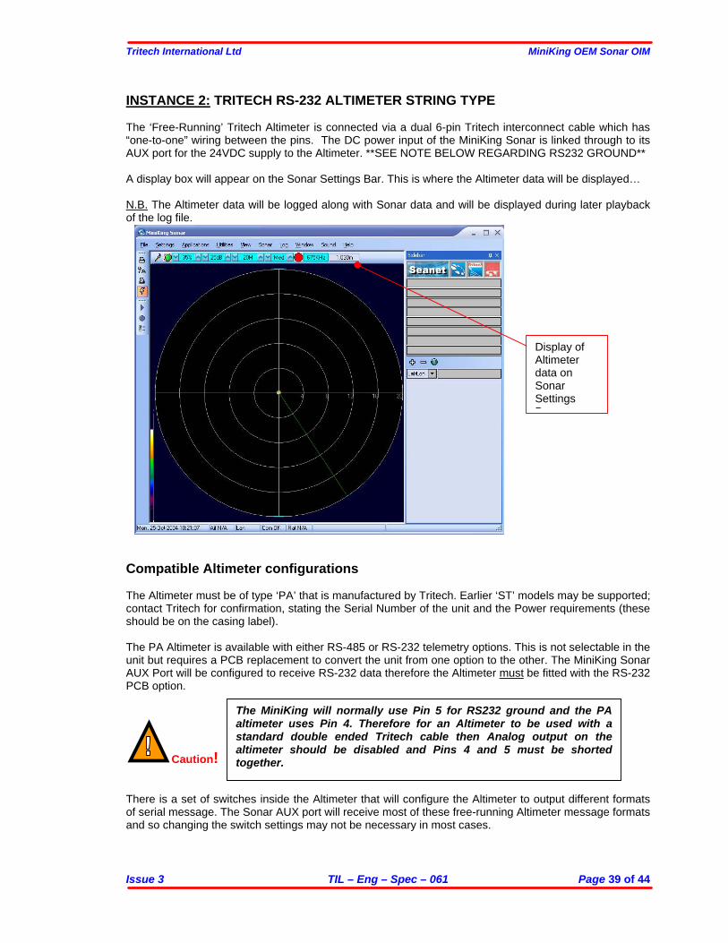
INSTANCE 2: TRITECH RS-232 ALTIMETER STRING TYPE The ‘Free-Running’ Tritech Altimeter is connected via a dual 6-pin Tritech interconnect cable which has “one-to-one” wiring between the pins. The DC power input of the MiniKing Sonar is linked through to its AUX port for the 24VDC supply to the Altimeter. **SEE NOTE BELOW REGARDING RS232 GROUND** A display box will appear on the Sonar Settings Bar. This is where the Altimeter data will be displayed… N.B. The Altimeter data will be logged along with Sonar data and will be displayed during later playback of the log file.
Compatible Altimeter configurations The Altimeter must be of type ‘PA’ that is manufactured by Tritech. Earlier ‘ST’ models may be supported; contact Tritech for confirmation, stating the Serial Number of the unit and the Power requirements (these should be on the casing label). The PA Altimeter is available with either RS-485 or RS-232 telemetry options. This is not selectable in the unit but requires a PCB replacement to convert the unit from one option to the other. The MiniKing Sonar AUX Port will be configured to receive RS-232 data therefore the Altimeter must be fitted with the RS-232 PCB option.
Caution! There is a set of switches inside the Altimeter that will configure the Altimeter to output different formats of serial message. The Sonar AUX port will receive most of these free-running Altimeter message formats and so changing the switch settings may not be necessary in most cases.
Display of Altimeter data on Sonar Settings B
The MiniKing will normally use Pin 5 for RS232 ground and the PA altimeter uses Pin 4. Therefore for an Altimeter to be used with a standard double ended Tritech cable then Analog output on the altimeter should be disabled and Pins 4 and 5 must be shorted together.

Tritech International Ltd MiniKing OEM Sonar OIM
Issue 3 TIL – Eng – Spec – 061 Page 40 of 44
If the PA Altimeter is a ‘Bathy Altimeter’ type then this is an RS-485, Interrogated unit (not free-running) and so the set of switches would need to be re-configured to change the unit to a free-running type (ensure to re-label the unit if changes are made!). The RS-485 would then need to be converted to RS-232 either by installing an external converter in-line or fitting the RS-232 PCB to the Altimeter. HINT: To confirm whether the PA Altimeter is a Free-running type, apply power to it and listen for the audible pings from the yellow/red cased transducer. If the unit is an Interrogated type then it will not ping.
Tritech International Ltd MiniKing OEM Sonar OIM
Issue 3 TIL – Eng – Spec – 061 Page 41 of 44
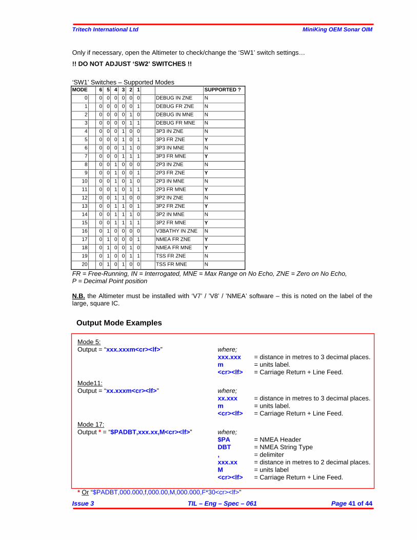
Only if necessary, open the Altimeter to check/change the ‘SW1’ switch settings… !! DO NOT ADJUST ‘SW2’ SWITCHES !! ‘SW1’ Switches – Supported Modes MODE 6 5 4 3 2 1 SUPPORTED ?
0 0 0 0 0 0 0 DEBUG IN ZNE N 1 0 0 0 0 0 1 DEBUG FR ZNE N 2 0 0 0 0 1 0 DEBUG IN MNE N 3 0 0 0 0 1 1 DEBUG FR MNE N 4 0 0 0 1 0 0 3P3 IN ZNE N 5 0 0 0 1 0 1 3P3 FR ZNE Y 6 0 0 0 1 1 0 3P3 IN MNE N 7 0 0 0 1 1 1 3P3 FR MNE Y 8 0 0 1 0 0 0 2P3 IN ZNE N 9 0 0 1 0 0 1 2P3 FR ZNE Y
10 0 0 1 0 1 0 2P3 IN MNE N 11 0 0 1 0 1 1 2P3 FR MNE Y 12 0 0 1 1 0 0 3P2 IN ZNE N 13 0 0 1 1 0 1 3P2 FR ZNE Y 14 0 0 1 1 1 0 3P2 IN MNE N 15 0 0 1 1 1 1 3P2 FR MNE Y 16 0 1 0 0 0 0 V3BATHY IN ZNE N 17 0 1 0 0 0 1 NMEA FR ZNE Y 18 0 1 0 0 1 0 NMEA FR MNE Y 19 0 1 0 0 1 1 TSS FR ZNE N 20 0 1 0 1 0 0 TSS FR MNE N
FR = Free-Running, IN = Interrogated, MNE = Max Range on No Echo, ZNE = Zero on No Echo, P = Decimal Point position N.B. the Altimeter must be installed with ‘V7’ / ’V8’ / ’NMEA’ software – this is noted on the label of the large, square IC. Output Mode Examples
Mode 5: Output = “xxx.xxxm<cr><lf>” where;
xxx.xxx = distance in metres to 3 decimal places. m = units label. <cr><lf> = Carriage Return + Line Feed. Mode11: Output = “xx.xxxm<cr><lf>” where;
xx.xxx = distance in metres to 3 decimal places. m = units label. <cr><lf> = Carriage Return + Line Feed. Mode 17: Output * = “$PADBT,xxx.xx,M<cr><lf>” where; $PA = NMEA Header DBT = NMEA String Type , = delimiter xxx.xx = distance in metres to 2 decimal places. M = units label <cr><lf> = Carriage Return + Line Feed. * Or “$PADBT,000.000,f,000.00,M,000.000,F*30<cr><lf>”
Tritech International Ltd MiniKing OEM Sonar OIM
Issue 3 TIL – Eng – Spec – 061 Page 42 of 44
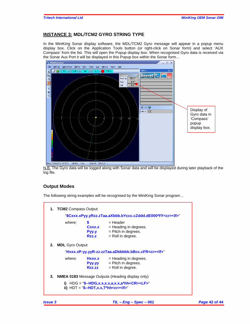
INSTANCE 3: MDL/TCM2 GYRO STRING TYPE In the MiniKing Sonar display software, the MDL/TCM2 Gyro message will appear in a popup menu display box. Click on the Application Tools button (or right-click on Sonar form) and select ‘AUX Compass’ from the list. This will open the Popup display box. When recognised Gyro data is received via the Sonar Aux Port it will be displayed in this Popup box within the Sonar form…
N.B. The Gyro data will be logged along with Sonar data and will be displayed during later playback of the log file. Output Modes The following string examples will be recognised by the MiniKing Sonar program…
1. TCM2 Compass Output
“$Cxxx.xPyy.yRzz.zTaa.aXbbb.bYccc.cZddd.dE000*FF<cr><lf>” where; $ = Header Cxxx.x = Heading in degrees. Pyy.y = Pitch in degrees. Rzz.z = Roll in degree.
2. MDL Gyro Output
“Hxxx.xP-yy.yyR-zz.zzTaa.aDbbbbb.bBcc.cFR<cr><lf>” where; Hxxx.x = Heading in degrees. Pyy.yy = Pitch in degrees. Rzz.zz = Roll in degree.
3. NMEA 0183 Message Outputs (Heading display only)
i) HDG = “$--HDG,x.x,x.x,a,x.x,a*hh<CR><LF>” ii) HDT = “$--HDT,x.x,T*hh<cr><lf>”
Display of Gyro data in ‘Compass’ popup display box.
Tritech International Ltd MiniKing OEM Sonar OIM
Issue 3 TIL – Eng – Spec – 061 Page 43 of 44
REGIONAL SETTINGS and AUX data It has been noted that Windows regional settings can prevent the flow of AUX data through the system. If the Aux device is connected correctly and operating but no data is displayed on the screen then the Regional settings may be preventing Seanet Pro from processing the data. In the Windows Control Panel open REGIONAL & LANGUAGE OPTIONS. Set the drop down list to “English(United Kingdom)” Press OK for the changes to take effect. Restart the Seanet Pro MiniKing software and check whether the AUX data is now displayed. If you wish to continue using your local settings then open REGIONAL & LANGUAGE OPTIONS. Set the region to the desired setting. Now press the “Customize” button and ensure that the DECIMAL SYMBOL is set to a “.” SERIAL PORT OUTPUT USING REMV4 UTILITY PROGRAM The MiniKing Serial AUX Port can be used to relay serial data messages to the surface and output on a Serial Port installed on the PC running the MiniKing Sonar program.
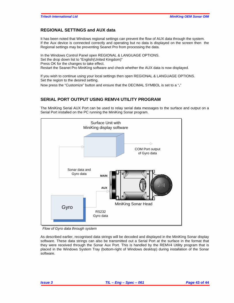
Flow of Gyro data through system As described earlier, recognised data strings will be decoded and displayed in the MiniKing Sonar display software. These data strings can also be transmitted out a Serial Port at the surface in the format that they were received through the Sonar Aux Port. This is handled by the REMV4 Utility program that is placed in the Windows System Tray (bottom-right of Windows desktop) during installation of the Sonar software.
Gyro
Surface Unit with MiniKing display software
MiniKing Sonar Head
RS232Gyro data
COM Port output of Gyro data
Sonar data and Gyro data
AUX
MAIN
Tritech International Ltd MiniKing OEM Sonar OIM
Issue 3 TIL – Eng – Spec – 061 Page 44 of 44
The REMV4 program can be opened by double-clicking on its Icon in the Windows System tray…
REMV4 Icon …For full details of REMV4 operation, consult the Seanet Remote Communications manual. REMV4 Software Setup for Sonar Aux Data Output 1. Open the REMV4 program by double clicking the REMV4 Icon in the Windows System Tray.
Alternatively, it can be opened through the Windows Start Menu (Start | Programs | MiniKing/Seanet | RemV4).
2. Enable a remote channel (Serial Port) for Sonar Auxiliary Port Data output. Select Settings | Channel from the RemV4 menu bar. Click on the ‘Setup’ button opposite your selected channel to configure Serial Port parameters. Once Serial Port parameters are set, check the ‘Enable Channel’ box to open the Serial Port.
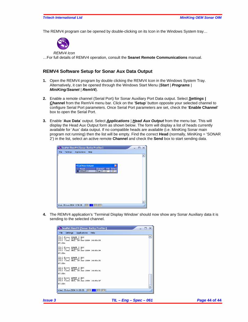
3. Enable ‘Aux Data’ output. Select Applications | Head Aux Output from the menu bar. This will
display the Head Aux Output form as shown below. The form will display a list of heads currently available for ‘Aux’ data output. If no compatible heads are available (i.e. MiniKing Sonar main program not running) then the list will be empty. Find the correct Head (normally, MiniKing = ‘SONAR 2’) in the list, select an active remote Channel and check the Send box to start sending data.
4. The REMV4 application’s ‘Terminal Display Window’ should now show any Sonar Auxiliary data it is sending to the selected channel.