Embed Size (px)
Citation preview
C.P. No. 604 sf, -“‘
---
MINISTRY OF AVIATION
AERONAUTICAL RESEARCH COUNCIL
CURRENT PAPERS
Minimum-Energy Ballistic Trajectories over a
, Non-Rotating Earth
bY
G. 0. Longden, M.A.
LONDON: HER MAJESTY’S STATIONERY OFFICE
I%2 *,
PRICE 6s 6d NET
U.P.C. No, 531.551.5:~1.455-~~623~451
C.P. No, 604
Lay, 195.5
&hum energy bclllistic trajectories over a non-rotating earth
G. l3. Longden, M.L.
The note generalties the optimization of ballistic trajectories to cover initial points higher than the aimjng point. This new optimum is compared with that used in previous notes, an& shown to be only slightly different. Some advantages in simplicity are suggested for the new method c.?f opt imizirlg. The work aims at providing a basic description of the optimum trajectories on which a variational analysis cczn be built in a later note.
_Ic_- - - - - * IY Ie . - . . - Me ---e--s -* -a----
Prev20urly issued as R.A.23, Tech i\iote No, G,V. 366 - A .R ,c , 19,285,
LIST OF CONTENTS
1 Introduction
2 Vacuum ballistic trajectories and their envelope
3 Optimum ballistic trajectories
4 Discussion and numerical examples
5 Conclusion
Gloss 'fry
References
Detachable Abstract Cards
LIST OF A??FZNDICES
Envelope of ballistic trajectories in a vacuum
Properties of optimum ballistic trajectories
Time of flight on optimum ballistic trajectory
LIST OF ILLUSTRA!TIONS
Diagrams of notation and geometrical disposition
Speed along trajectories plotted against ground range
Speed along trajectories
Variation of climb angle along trajectory
Height of trajectories plotted against ground range
Height of trajectories
Variation of cut-off velocity and flight time with height
Variation of cut-off speed with impact range
Variation of cut-off climb angle with impact range
Variation of flight time with impact range
3zz.E
3
4
7
IO
12 .
12
13
An-pendix
I
II
III
Figure
I
2
3
4
5
6
7
8
9
IO
-2-
I Introduction
.
.
1.1 The work in references 1 and 2 has been based on vacuum ballistic trajectories for which the climb angle is chosen to maxtize the range from ground to ground. In practice, the boost phase of a rocket flight will occupy an appreciable part of the flight, covering perhaps 5% of the maximum range attained by the ballistic missile. The missile'will actually set out on its ballistic trajectory when motor thrust ceases at the cut-off point high above the earth surface. It appears reasonable to maximize the range from the cut-off point to the ground rather than including an LlzaginRry portion of the trajectory traced backwards from the cut-off point to the ground.
Rtaximizing the range covered over just the free flight (ballistic) part of the trajectory will not give the greatest range from launch to impact. h slightly lower climb angle at cut-off enables more ground to be covered during the boost phase with very little loss in range over the ballistic part of the trajectory. However, maximum range between launch aed impact may not be required. In some schemes of radar guidance, it is possible that a ground staticnmaybe sited roughly below the cut-off point. Since such a ground station would necessarily lie on friendly ground and ahead of the launching site, the operational range would be measured most effectively from cut-off to impact.
Trajectories optimized from cut-off to impact offer two simplifications which may justify their substitution for the ground optimized trajectories used previously (references I and 2). In the first place, since the range from cut-off to ground is a maximum, error3 in range are insensitive to errors in the climb angle at cut-off, depending on only second order terms. This may be expressed in the manner of reference 2 by saying that the critical direction for the velocity lies along the direction of the desired velocity. It means that if the climb angle is adjusted to be approximately correct (within say 3 mil s), only the speed of the missile need be measured in order to determine the range to irnpact.
The second advantage lies in the partial separation of the problems of optimizing the boost trajectory end optimizing the ballistic trajectory. The analysis of the ground optimized trajectories used in references 1 and 2 is somewhat complicated by the rather artificial concept of the range from ground tc ground. In order to find the velocity required to cover a given range frcma given cut-off point it is necessary to solve a cubic equation fer the ground optimised trajectory. This and similar difficulties are overcome by optimizing the ballistic trajectory from cut-off to ground. Unless otherwise indicated in the remainder of this note, the term optimum trajectory will be used in the sense that the climb angle at cut-off is chosen tc give maximum range from cut-off to impact.
I .2 Apart from the different method of optimising the trajectories the assumptions are the same as in references 1 and 2. The work deals with vacuum ballistic trajectories &cut a spherical ncn-rotating earth. The cut-off point will, be well above the atmosphere so that drag caused by the air will be entirely negligible until the missile re-enters the atmosphere near the target. Terminal deflections of the missile from a vacuum ballistic trajectory caused by the atmosphere are ignored here. It has been shown in reference 1 that the mean of such deflections is small compared with the total ground range traversed.
The trajectories are considered about a non-rotating spherical earth. Allowance may be made for earth rotaticn between particular end-points but since the correction is in a variable direction with respect to the trajec- tory, it is more convenient to ignore the spin of the earth in this simple
-3-
general treatment. Allowance for earth rotation will be considered in a later note.
In harmony with the assumption of a spherical earth, the acceleraticn due to gravity is assumed to be that of a uniform sphere. Thus the force per unit mass exerted by the earth on the missile is directed towards the centre c of the earth and varies inversely as the square of the distance fmmthe centre of the earth. The acceleration due to gravity at the earth surface has been taken as 32 ft/sec2. The radius of the earth is assumed to be 3437.75 n. miles so that one nautical mile at the earth surface subtends one . minute of arc at the oentre of the earth.
The notation is basically the same as that in references 1 and 2. Most of the mathematics is contained in three appendices, through which equations are numbered ccnsecutively. A few properties of optimum trajectories are outlined in the main text and s umnarized in the conclusions.
2 Vacuum ballistic trajectories ad their envelope
2.-l Appendix 1 contains a derivation of the trajectory of a ballistic missile in a vacuum. The equations of moticn have been obtained in more detail in reference 9, and the analysis follows closely on that of references I and2. Some of the earlier work is reproduced in order to maintain some independence. The later parts of the argument proceed differently due to discarding the ccncept of range from ground projection to impact.
2.2 Certain salient features of vacuum ballistic trajectories may be pointed out in consequence of results in the Appendix. The results are most easily expressed in terms of a speed parameter p (see equation (8)) whioh is non- dimensional and equal. to
.
where r is the distance of the missile from the centre of the e;arth, v is the missile speed, g is the acceleration due to gravity at the earth surface and R is the radius of the earth.
Any vacuum ballistic trajectory takes the form of an ellipse with one focus at the centre of the earth. The length of the major axis is
2r 2-p see equation (18)
in which formula any instantaneous values of the variables r, p may be substituted. In particular the initial values may be used, so that given the initial height ‘and the speed of the missile, the length of the major axis of its trajectory is determined. The initial point on -the ballistic trajectory is the point at which all motor thrust ceases, and so will be referred to in general as the cut-off point. &
The constancy of the expression for the major axis may be deduced from the principle of conservation of energy. The only acceleration of the missile is assumed to be due to the attraction of the earth of magnitude 6
gR2 r2
-4-
acting towards the centre of the earth. By integration, it follows that an expression for the potential energy of the missile at a range r from the centre of the earth is
c ,d r
per unit mass osthe missile. Since the kinetic energy of the missile per unit mass is&v , the total energy of the missile is
and this remains constant along the trajectory. But by the definition of p in equation (8),
Thus 2Er = gR2p - 2gR2
i.e. 2r 2-p =
Since the values of g, R and E are all constant along the trajectory, it follows that the fraction
also remains constant over the trajectory. As mentioned above, it represents a length which may be identified with the major axis of the orbit.
It may be observed that the dZl,ensionless parameter p takes the form of twice the quotient of the kinetic and potential energies of the missile.
2.3 Another quantity assooiated with the elliptical trajectory is the length of the latus rectum which is quoted as
2rp cos28
(see equation 19) where the angle 8 is the climb angle between the missile velocity and the local horizontal, and is measured positively in the upwards sense. This quantity may be shown to remain constant over the trajectory by the principle of constancy of angular momentum about the centre of the earth. The length of the l&us rectum depends not only on the speed and position of the missile but also on the direction of the velocity.
2.4 A convenient way of determining the greatest distance which can be travelled starting from a certain cut-off point is to study the envelope of trajectories. It is assumed that the cut-off point and cut-off speed are
-5-
specified., but that the trajectory maybe altered by choice of the climb angle at cut-off. The envelope of the trajectories in such circumstances has been derived at the end of Appendix I where it is shown to be an ellipse called the bounding ellipse.
Through any point inside the bounding ellipse, it is possible to find a trajectory starting frcxn the ,cut-off point with the stated speed. Points outside the bounding ellipse cannot be reached, and points on the bounding ellipse can just be reached by a missile with the given cut-off conditions.
The bounding ellipse has one focus at the centre of the earth and the other focus at the cut-off point. The size of the bounding ellipse is typified by the length of the major axis and this is
2+p, , rl -
2-P,
where the suffix 1 denotes v<alues at cut-off. For varying values of the speed parameter p, the corresponding bounding ellipses form a con-focal system. For example, when thevalue of p = 2/3, the length of the major axis of the bounding ellipse is 2r, so that the missile is able to reach a point which is a distance r, from both the cut-off point and the centre of the earth. This means that the missile is capable of traversing an arc of sixty degrees over the earth surface between two points both at a "height" r, (measured from the centre of the earth). The following table shows the cut-off speed required to satisfy the relation p = 2/J at three heights above the earth.
Cut-off speed when p = 2/3
Height (n. miles) I 0 50 100 Speed ft/sec 21,116 20,964 20,816
m.p.h. 1 14,397,14,294 I 14,192
When the value of p = I, the length of the major axis of the bounding ellipse is 3r so that the missile is able to reach a point distance r from the centri of the earth at the opposite side of the world. The fol 1 owing table shows the cut-off speed required to satisfy the relation p = 1 at three heights above the earth.
Cut-off speed when p = 1
Height (n. miles) 0 50 100 I , Speed ft/sec 25,862 25,676 25,494
i m.p.h. ~17,633 ,17,506 1 17,382 4 *
As the value of p tends towards 2, the bounding ellipse degenerates into the circle at infinity, with the consequence that the missile can reach any point in space. The necessary speeds are 42 times those in the previous table and are shown in the table below.
z
-6-
Cut-off speed when p = 2
Height, (n. miles) 0 ' 50 j 100 Speed (ft/sec) 36,575 36,312 t 36,054
m,p.h. i 24,337 24,757 I ! 243Q
2,5 By a well-known property of an ellipse, the sum of the distances from any point on the ellipse to the two foci is a constant (equal to the length of the major axis). Hence if in Fig.l(b) a missile is capable of just reaching a point Q on the earth surface from the cut-off point P, the length of the major axis of the bounding ellipse must be
R+d
where R is the radius of the earth and d is the distance PQ. If the missile were fired vertically up;vards with the same speed from tne same cut-off point, it would reach a maximum height of h' above the earth surface where
2(R + ht) - r, = R + d
i.e. h' = $(r, + d - R)
c $-(d+h)
where h is the height of the out-off point above the earth surface. For example a missile capable of travelling 2333 n. miles from a cut-off point 400 n. miles high would reach a height of 12cO n. miles if it were directed vertically.
3 Optimum ballistic trajectories
3*-l The geometrical propertie s of the bounding ellipse may be used to deduce the form of the optimuim ballistic trajectory. In Fig.l(b), let P be the cut-off point and Q the desired impact point which the rmissile must just reach. It follows that the cut-off speed must be chosen so that the bounding ellipse with foci at P and the centre of the earth 0 shaU pass through Q. The tangent to an ellipse bisects the angle between the focal lines, the lines from the contact point on the ellipse to each of the two foci. Thus the direction of the bounding ellipse at the impact point Q must bisect the angle between the lines PQ and OQ. NOW at the point Q, the optimum ellipse from P to Q touches the bounding ellipse which forms its envelope, and so the tangent to the optimum trajectory at Q coincides with the tangent to the bounding ellipse. Thus the tangent at Q to the optimum trajectory also bisects the angle between the lines PQ and OQ. But the trajectory from P to Q is an ellipse with one focus at the centre of the earth 0. Since the tangent at impact Q to the optimum trajectory must bisect the focal lines, it follows that the second focus of the optimum trajectory lies on the line PQ.
Thus the optimum trajectory from P to Q is the ellipse which has one focus on the straight line joining P to Q.
-7-
This property of optimum trajectories has been noted in reference l.cor the particular case in which both P and Q lie on the earth surface at equal distanoes from the earth centre.
3.2 Since the second focus F of the optimum trajectory lies on the line PQ, it follows that the lines PQ and OP are focal lines from the cut-off point P. Hence the climb angle at cut-off on an optimum trajectory is such that the . velocity bisects the angle between the straight line PQ to the target and the upward vertical OP.
It has been suggested (by Mr. G.H. Seaton of Convair, U.S.A.) that a * profitable trajectory during the later part of boost might be one on which the missile always climbs at such an angle as to be the optimum should free flight cormence at that instant. If the optimum climb angle is interpreted as that required to reach a given target Q, the missile would fly in such a direction as tc bisect the angle between the lines PQ and OP. It follows from the geometry of the ellipse that this locus would be an ellipse with foci at the centre of the earth 0 and at the impact point Q. It can be shown that such a locus would not demand very large sideways acceleration. For example, just before cut-off at a height of 100 n. miles, a missile guided towards a target 2400 n. miles away (in a straight line) would require Fg acceleration normal to the trajectory.
3.3 The position of the second focus F is deduced in Appendix II. If the cut-off point is at a height h in excess of the height of the impact point (i.e. h =r - of PQ towarL
r ), the position of F is at a distance &h from the mid point thz cut-off point 9. Given the two foci at F and 0, the centre
of the earth, the optimum trajectory may be sketched readily, since it passes thrcughP and Q. e
Various other properties of optimum trajectories are deduced in Appendix11 including explicit formulae for the cut-off speed and climb angle required to reach a given impact position. The speed at cut-off vl is given by equation I (29) as
2 5 =
pr R2 (d-h) rs I
where d is the straight line distance fmm cut-off to impact,
h is the height of the cut-off point in excess of the impact height
and s is the semi-perimeter of the triangle formed by the cut-off point, the impact point and the centre of the earth.
The variables d, s, h appear to be the most natural to use in work on optimum trajectories since formulae often take their simplest formwhen expressed in their terms. Possibly one exception is the climb angle at cut- off, 0, which equation (33) expresses as
sin P 0, = 6 arctan
t
r2 2 rl - r2 cos Q 2 3
c
where r, r2 are the distances of the cut-off point P and the impact point Q from the centre of the earth, and the angle G2 is the angle subtended at the centre of the earth by PQ. The corresponding formula (37) in terms of the variables d, s, h is
-8-
8, =
The equation of the optimum ellipse is quoted in the Appendix as . equation (4.0).
3.4 Alternatively it may be required to find how far a missile with a given speed will travel from a given cut-off point if the climb angle is chosen for optimum range. The distance PQ is shown by equation (55) to be
d =
where
2 I‘1 9
P, = ‘!3R2
Also the optimum clixib angle is, by equation (57)
8, = srctan 1 c r2 - 9 P, ('1 +r2) 'i 2 P, l
rl - r2 f B Plr2 1
3.5 The final ApperLaix III comprises analysis to find an expression for the time of flight from cut-off to impact. This is shown by equation (69) to be
where s = 3 (9 + r2 + d) the semi-perimeter of the triangle formed by the cut-off point,impaot point and the centre of the earth.
3.6 Since the condition which optimizes the trajectory from P to Q is symmetrical in terms of the points P and Q, the same trajectory is also the optimum from Q to P (when traversed in the opposite sense). It is proper to speak of the optimum trajectory between P and Q since the pathis unique and does not depend on the direction of motion. Since the velocities at any point are the same in magnitude and direction and merely differ in sense with the way the missile is flying, the speed at impact at Q on arrival from P is the same as the speed at Q needed to reach P on the optimum trajectory. Thus the speed and dive angle at impact maybe calxilated from the same formulae as for cut-off merely by interchanging the distances relating to cut-off and impact (i.e. reversing the sign of h)-
The locus of cut-off point,, p from which the missile just reaches the target with a given speed is the same as the locus 'of points which can just be reached by projecting the missile from the impact position with an
-Y-
equal but opposite speed. This is a bounding ellipse described about the impact point and centre of the earth as foci. Since the energy at impaot is determined by the speed, and the energy remains constant along a vacuum ballistic trajectory, the locus maybe described in another way. The locus of cut-off points at which the missile has the same minimum energy needed to carry it to the target at Q is the bounding ellipse with foci at 0 and Q. This * same elliptical locus has been noted above in section 3.2 as a possible boost trajectory along which the climb angle is always the opt- for reaching the target at Q.
4 Discussicn and numeric-al examples
4.1 One immediate question posed by the new method of optimisation is what difference there is between the new optimum trajectories and the former ground- optimised trajectories of references 1 and 2. This may be answered by a numerical example. On a trajectory optimized between two points on the ground 2500 n. miles apart, a point 100 n. n;iles high is at a ground range of 2350 n. miles from the target. If cut-off were chosen at 100 n. miles high so as to use such a ground optimised trajectory, the cut-off velocity would be 17,691 ft/sec at an angle of 32.1 degrees to the local horizontal. On the other hand, if an optimum trajectory is chosen from the same cut-off point to the same target at a ground range of 2350 n. miles, the velocity required is 17,680 ft/sec at 34 degrees to the local horizontal. Hence over an impact mange of 2500 n. miles, the difference in optimization is likely to amount to IO ft/sec in speed (about 0.0694 and about two degrees in climb angle. Maxi- mizing the range from launch to impact rather than cut-off to impact is likely tc lead to cut-off climb angles a little nearer the horizontal.
i 4.2 It is instructive to find what speed is required tc reach the t‘arget when the cut-off climb angle varies on either side of the optimum. The refev- ant formula is eqaticn (17) in the Appendices. The following Table shows values of the speed for the same example as above, with the cut-off point ‘ 100 n. miles high and a target at a ground range of 2350 n. miles away.
Variation uf cut-off speed with climb angle
I I Climb Cut-off angle (degrees) / 22 24 26 28 30 ’ 32
, speed (ft/sec) 18,266 18,082 17,933 17,822 97,744 17,697
Clizib angle (degrees) 1 34 36 38 40 42 -I 44 i Cut-off speed (ft/sec) 1 17,680 17,695 1 17,743 17,822 ?7,933 , 18,081
From this table it appears that climib angles within a couple cf degrees of the optimum do not require much more speed,at cut-off, and the cut-off speed remains within one per cent of the optimum over an interval of 26 degrees.
4.3 From the formulae developed in the Appendices, some numerical examples have been computed and graphs drawn. Where a typical cut-off height has been required, a value of 100 n. miles has been taken. Ranges to impact have been chosen in steps of five hundred miles out to a value of 5500 n. miles, which t
represents roughly a quarter of the circumfermce of the earth. Where a typical impact range has been required, a value of 25CC n. miles has been used as it is roughly the mean rcange considered in this note. It should be d remarked that the definition of impact range is the ground range from below the cut-off point to Lipact ,uld differs fmin the ground-to-ground range of reference 2.
- 10 -
.
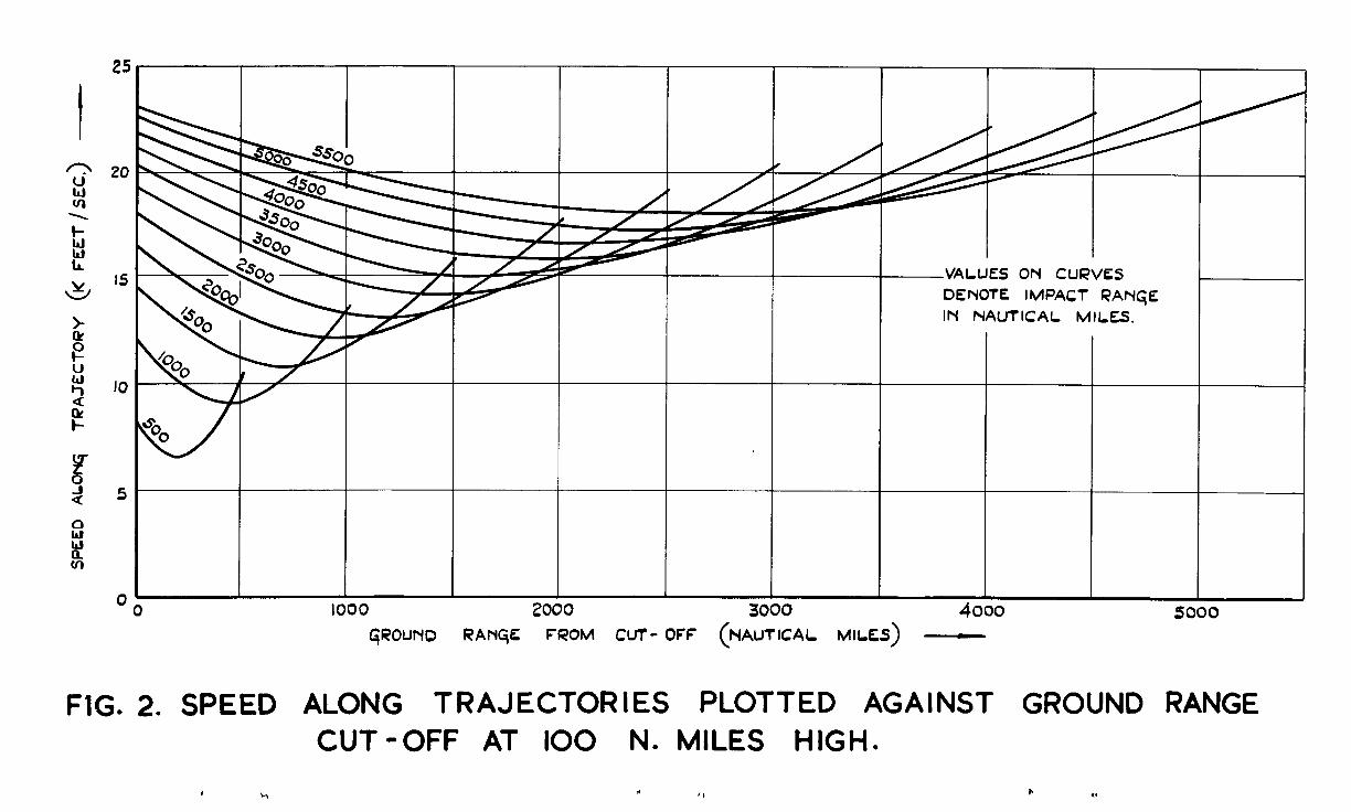
4.4 The first few graphs show the variation of missile velocity and height along a number of trajectories. For all these graphs, the cut-off height is t&en to be 100 n. miles. Fig.2 shows the variaticn cf missile speed with ground range over eleven trajectories with impact ranges from 500 to 5500 n, miles. l3ecause the cut-off occurs at a greater height than im?nct, the speed is less at cut-off than at impact, and the curves are not symmetrical about the mid-points. The lack of symnetry beccmes less obvicus as the impact range increases but remains appreciable. These curves may be compared with the correspcnding curves in Fig.1 of reference 2 for vtnich the cut-off height was taken equal to the impact height. The formula used in computing the results is shown as equaticn (42).
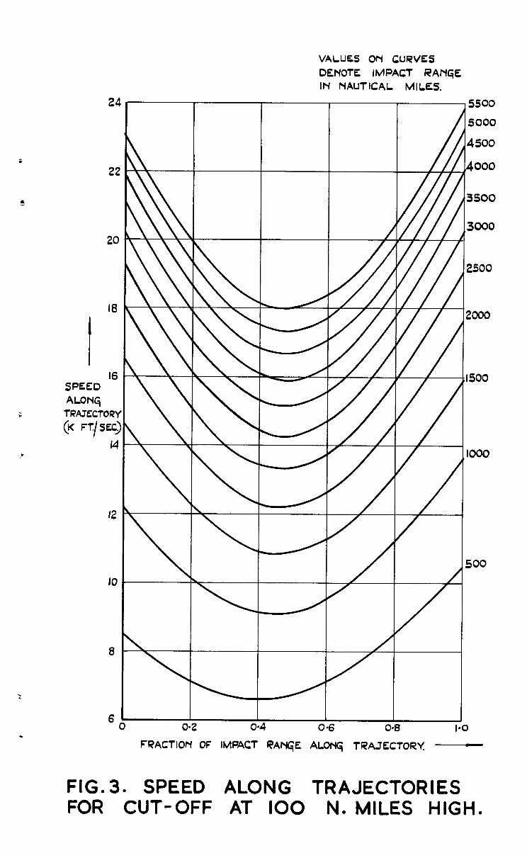
In Pig.3, the same data have been plotted slightly differently as functions of the fractional range to the txget, the quotient of the ground range to the impact range. This permits more accurate reading of the speeds in many circums4znces.
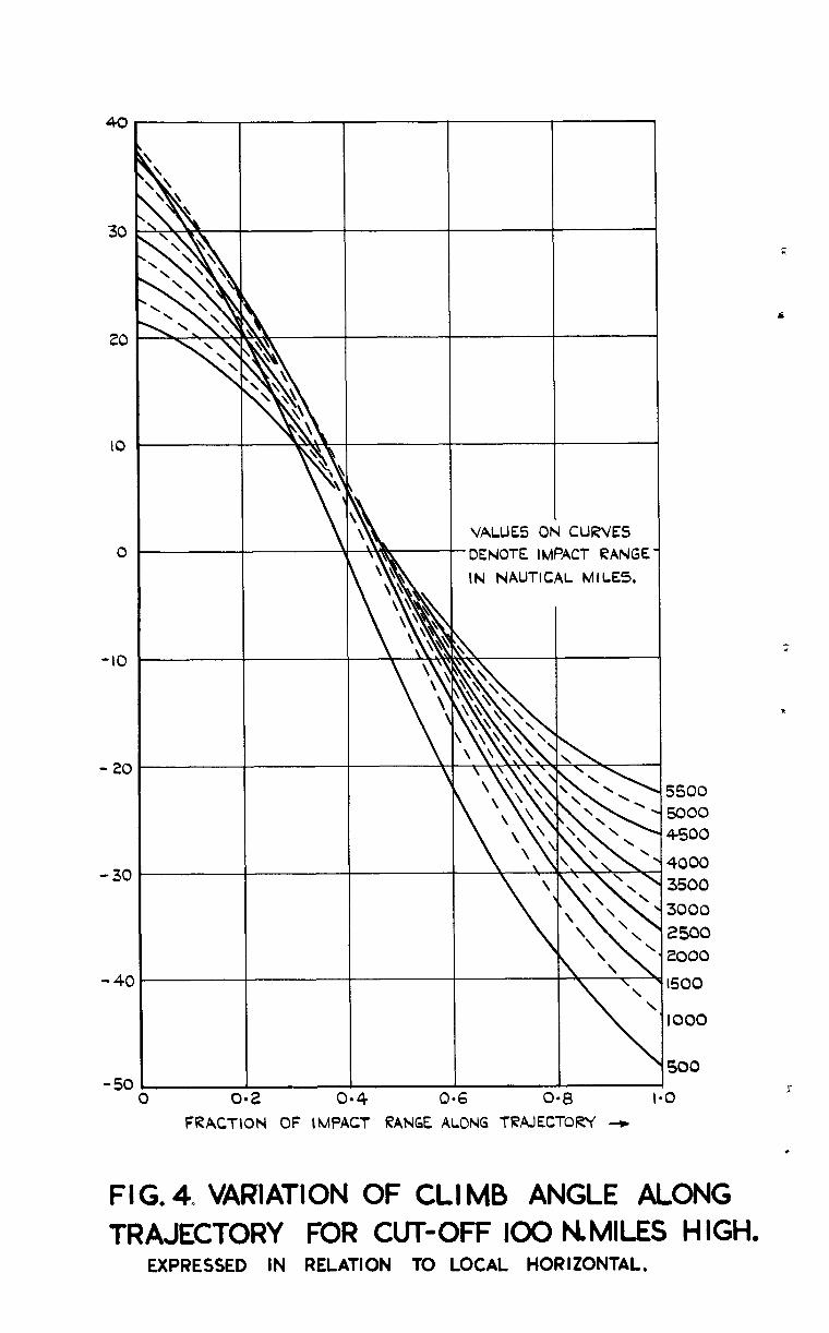
In Fig.4 values of the climb (and dive) angle have been plotted along the same trajectories as for the speed above. The results are plotted against fractional ground range only as overlapping causes too much confusion if the curves are shown similarly to Fig.2. The formula for thti climb angle is quoted as equation (47). It may be observed that when the impact rage approaches the order of magnitude of the cut-off height (100 n. miles) there is a considerable displacement of the curve compared with the remainder of the family. All the curves of climb angle for impact ranges of 1000 n, miles and greater pass through a v,slue close to 6 degrees at 0.4 of the way to the target. In order to distinguish neighbouring curves, the lines have been drawn alternately full and broken.
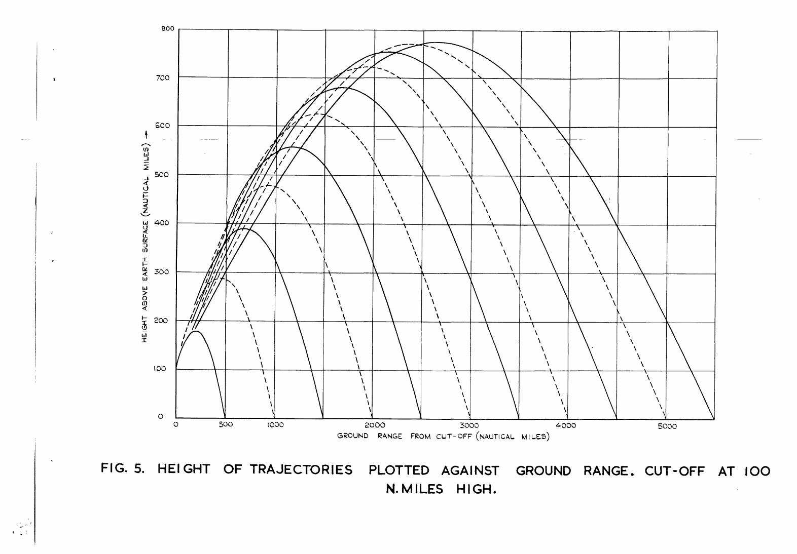
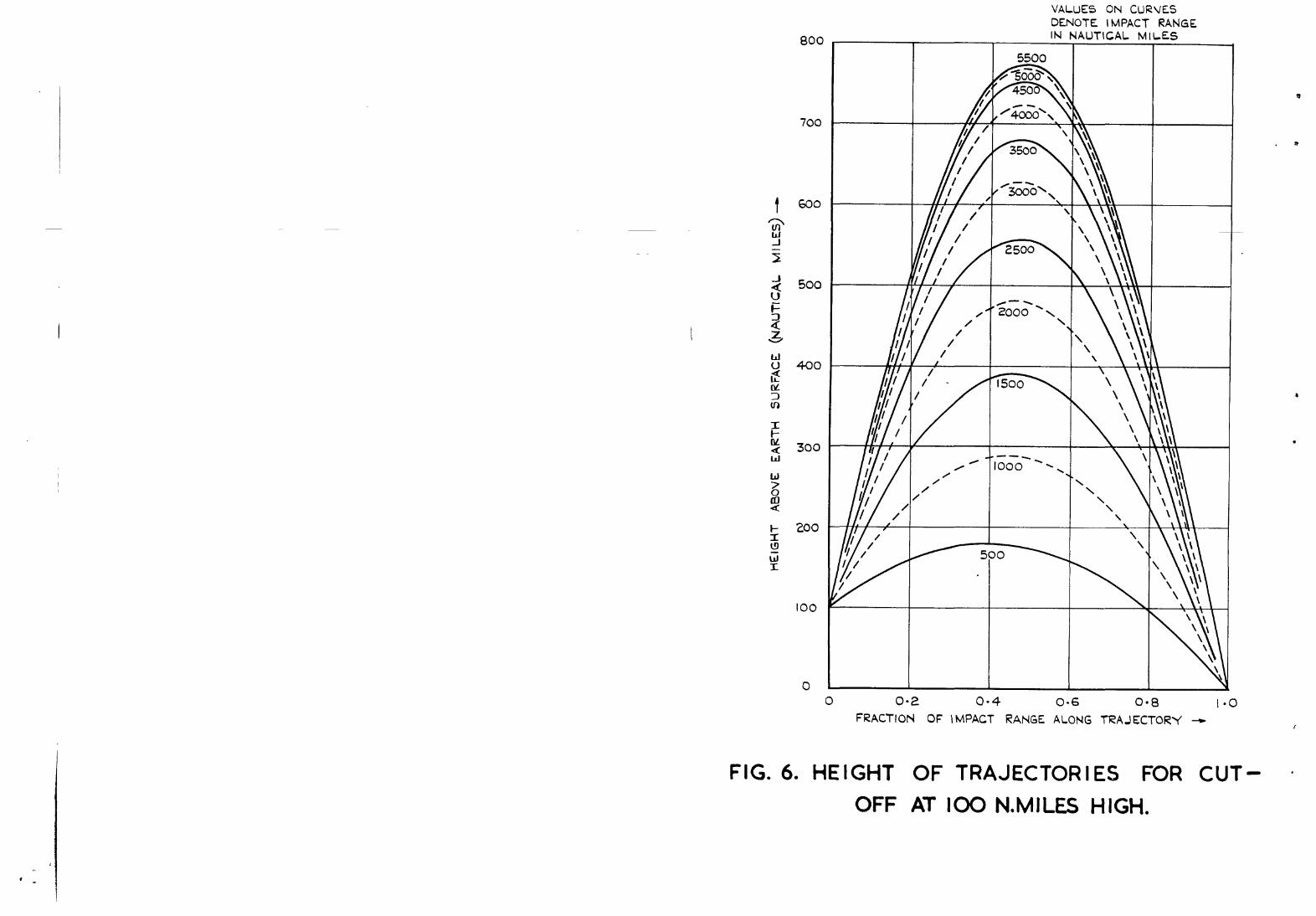
In Figs.5 and 6, the height of the trajectories above the earth surface has been plotted in the sine wCay as the speed in Figs. 2 and 3. The formula fcr the missile height is equation (40). These curves may be compared with Figs.4 and 5 of reference 2 in which the cut-off is assumed to occur on the ground. It will be noticed that for impact ranges greater than 5509 n. miles, the greatest height attained on the trajectory starts to decrease as the impact rLange increases.
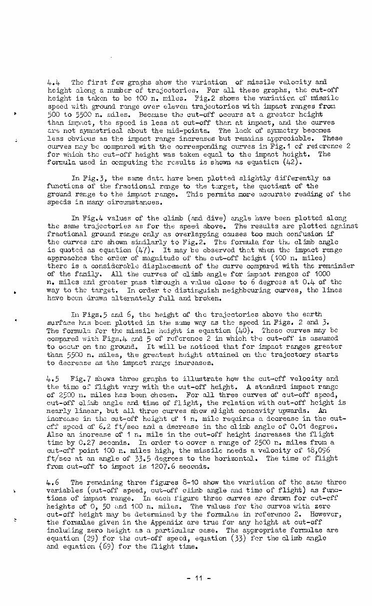
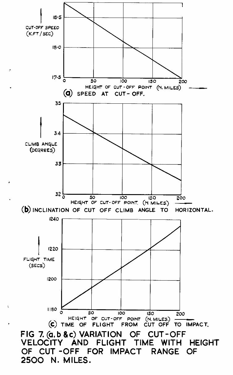
4.5 Fig.7 shows three graphs to illustrate how the cut-off velocity and the time of flight vary witn the out-off height. A standLard impact range of 25CC n. miles has been chosen. For all three curves of cut-off speed, cut-off climb (angle <and time of flight, the relation with cut-off height is nearly linear, but all three curves show slight concavity upwards. An increase in the cut-off height cf 1 n. mile requires a decrease in the cut- off speed of 6.2 ft/sec and a decrease in the climb angle of O.O? degree. Also an increase of I n. mile in the cut-off height increases the flight time by 0.27 seconds. In order to cover a range of 2500 n. miles from a cut-off point 100 n. miles high, the missile needs a velocity of 18,096 ft/sec at an angle of 33.5 degrees to the horizontal. The time of flight from cut-off to impact is l207.6 seconds.
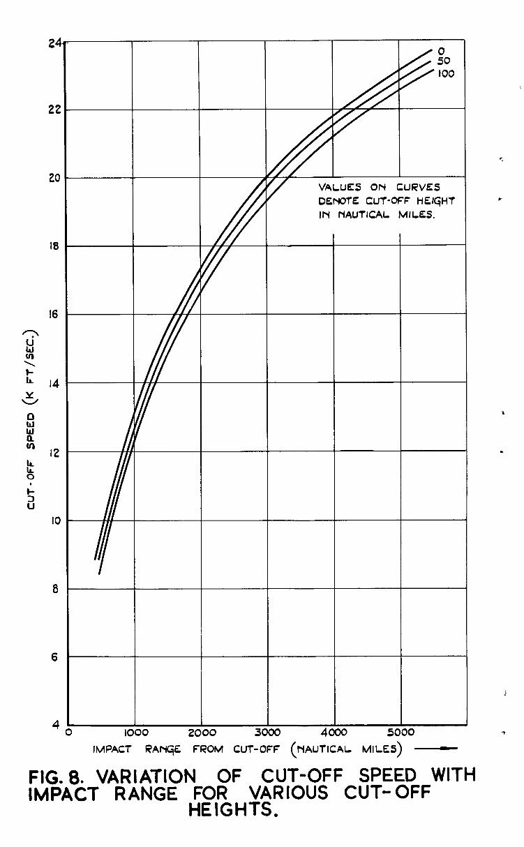
4.6 The remaining three figures 8-10 show the variation of the same three variables (cut-off speed, cut-off climb angle ‘and time of flight) as func- tions of impact range. In each figure three curves are drawn for cut-cff heights of 0, 50 and 100 n. miles. The values for the curves with zero cut-off height may be determined by the formulae in reference 2. However, the formulae given in the Appendix are true for any height at cut-off including zero height as a particular cnse. The appropriate formulae are equation (29) for the cut-off speed, equation (33) fcr the climb angle and equation (69) for the flight time.
- 11 -
The curves of climb angle in Fig.9 are worthy of comment since it is apparent that there is a wide divergence for short impact ranges, between cut- off on the ground and cut-off at some height. This may be understcod by remembering that the optimum direction for projection bisects the angle between I the line of sight to the target ,and the upward vertical. To reach a point at the same height, the optimum angle of projection is 45 degrees over ranges sufficiently short for neglecting curvature of the earth. However, if, the c target is at a lower height, the missile is able to drop on it and very small angles ef projection mayb e the best. For impact ranges much greater than the cut-off height, the optimum climb angle at cut-off differs little from that at zero cut-off height. As shown in reference 2, this climb angle is
where Q2 is the angle subtended by the trajectory at the earth centre.
5 Conclusion
The note proposes optimizing the range covered between cut-off end impact showing that this leads to results very similar to those previously obtained. Simple formulae are developed for the speed and climb angle required tc reach a specified aiming point. The climb angle bisects the angle between the straight line to the target and the upward vertical. Some numeri- cal values have been ccmputed and are shown as graphs for impact ranges up to 5500 n. miles.
In order tc cover a ground rrnge of 2500 n. miles from a cut-off point 100 n. miles high, the cut-off velocity should be 18,096 ft/sec at Lan angle of 33.5 degrees to the horizontal. The flight time is 1207.6 seconds.
c;Loss ary
Suffix 1 denotes values of variables at cut-off
Suffix 2 denotes values of variables at impact
Impact range is defined as the range measured over the earth surface from below the cut-off point to the impact point
a
A
b
P
d
e
e;
h=
length of the semi-major axis of elliptical trajectory
quotient of eccentricity ard semi-lotus rectum of elliptical trajectory: see equations (4) and (14)
length of the semi-minor Cexis of elliptical trajectory
eccentric angle used in parametric representation of ellipse: see equations (65) and (67)
straight line distance from cut-off to impact
eccentricity of elliptical trajectory
acceleration due to gravity at earth surface (32 ft/sec')
rl - r2 height of cut-off point in excess of impact point
- 12 -
Glossa~ (Ccnt'd.)
. H angular momentum per unit m.zss of missile about centre of
earth (see equations (3) and (6))
a climb angle; inclinaticn of trajectory to local horizontal
cp angle subtended at ce;ntre of earth between missile and the apogee of the trajectory
9 angle subtended at centre of earthbetween missile and cut-off point
2 P parameter related to missile speed: equalsr%
see equation (8) gR
9 parameter related to climb angle: equ,als tan 0 see equation (9)
r distance of missile from centre of the earth
R radius of the earth (taken as 3437.75 n. miles)
S = -5 ' (r, + r2 + d) : semi-perimeter impact and centre of the earth
t time I
u = -
V speed of missile
REXSREXCES
Ho. Author
1 D.G. King-Hele and Miss D.M.C. Gilmore
2 G.B. Longden
3 D.G. King-Hele and Miss D.M.C. Gilmore
of triangle formed by cut-off,
Titles, etc.
Long Range Surface-to-Surface Rocket fissiles: Properties of ballistic trajec- tories in vacua UnlxAlished 1d.O.A. Report.
Preliminary investigation of guidance accuracy needed for long range ballistic rockets Unpublished X.3.k. Report.
The effect of various design parameters on the weight of long range surface-to- surface ballistic rocket missiles Part II
‘unpublished X. O,A, Report.
- 13 -
Envelope of bCallistic trajectories in a vacuum
Let (r, S) be the polar coordinates of the missile with respect to the centre of the earth as origin. Fig.l(a) shows a diagram intended to illustrate some of the notation. The only force assumed to act on the missile is that due to gravity, directed towards the centre of the earth and varying inversely with the square of the distance to the centre of the earth.
Let g be the acceleration due ta gravity at the earth surface, be the radius of the earth (assumed spherical). The force acting on missile per unit mass is
R2 -g--
r2 along the radius
As quoted in reference I, the equations governing are
'2 F-r.@ R2 = -g.- r2
1
- l g (r2 * i) = 0 r
andR the
the motion of the missile
(1)
(2)
where t denotes the time, and differentiation with respect to time is denoted as usual by a dot.
Equation (2) may be integrated at once to give
r2 . 1; = H (31
where H is a constant depending on the initial conditions. It may be noted that equation (3) may be deduced immediately from the principle of conservation of angular momentum about the centre of the earth. Thus the constant II equals the angular momentum in the trajectory per unit mass of the missile.
As shown in reference 1, the differential e quation (1) may be solved in terms of
u = 2. I‘
to give
u = 1 -GE r - H2
+ A cos (MO) (4-J
where A, Q. are constants of integration to be determined from the initial conditions. The equation (4) represent s an ellipse with one focus located at the origin, the centre of the earth.
- 14 -
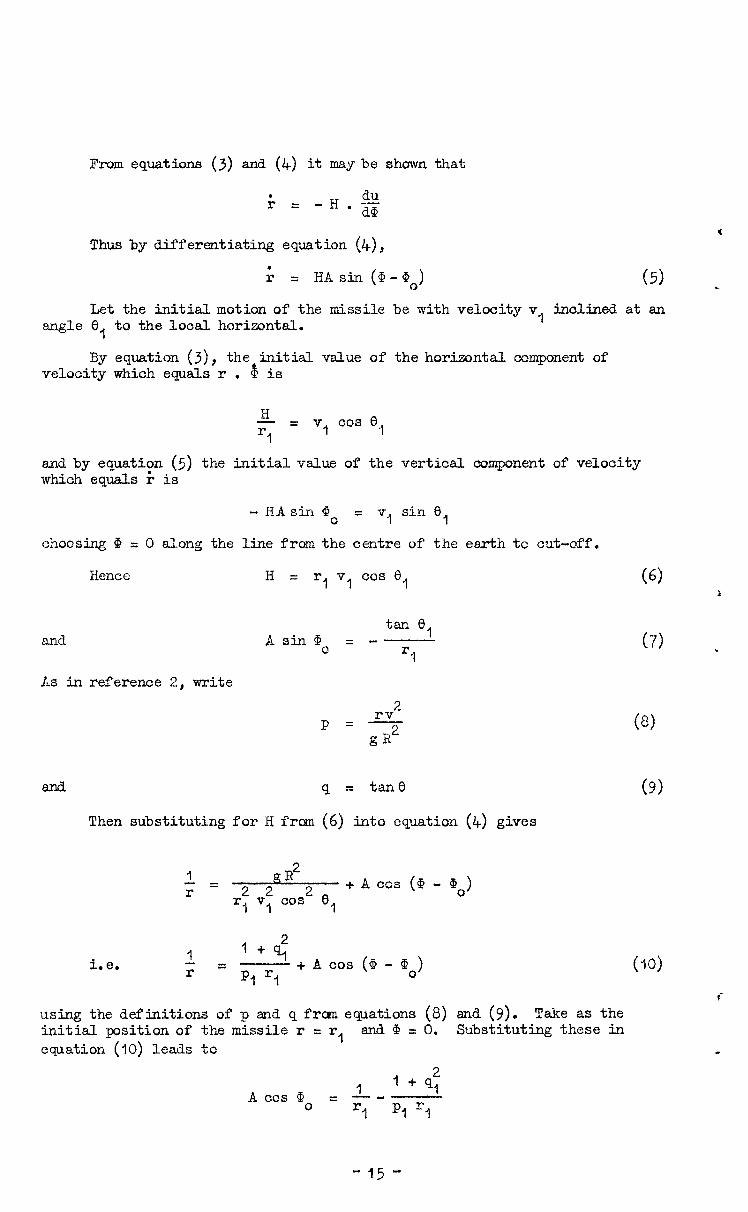
From equations (3) and (4) it may be shown that
Thus by differentiating equation (4),
ii = HA sin (&-@O) (5) L
angle Let the initial motion of the missile be with velocity v, inclined at an 0, to the local horizontal.
By equation (3), the initial value of the horizontal component of velocity whioh equals r . 45 is
H -= rl
v, cos 8 1
and by equation (5) the initial value of the vertical component of velocity which equals 5 is
- HAsin Q. = v, sin 8,
choosing (3 = 0 along the line from the centre of the earth tc cut-off.
Hence Hz r, v, cos 8 1 (6) i
Asida = - tan e,
5 (7) , and
Xs in reference 2, write 2
p=+ gR
Q = tane
(8)
(9) Then substituting for H frcxn (6) into equation (4) gives
1 = 2 2”R2 r + A cos (@ - Qo)
'I v1 cos 2 5
i.e. 1 1 + 91'
r = PI r, + A cos (a - go) C-10)
r using the definitions of p and q from equations (8) and (9). Take as the initial position of the missile r = r, and G = 0. Substituting these in equation (IO) leads to f
R
1 A cas Go = - - 1 + s;’
rl PI 5
- 15 -
.
c
3
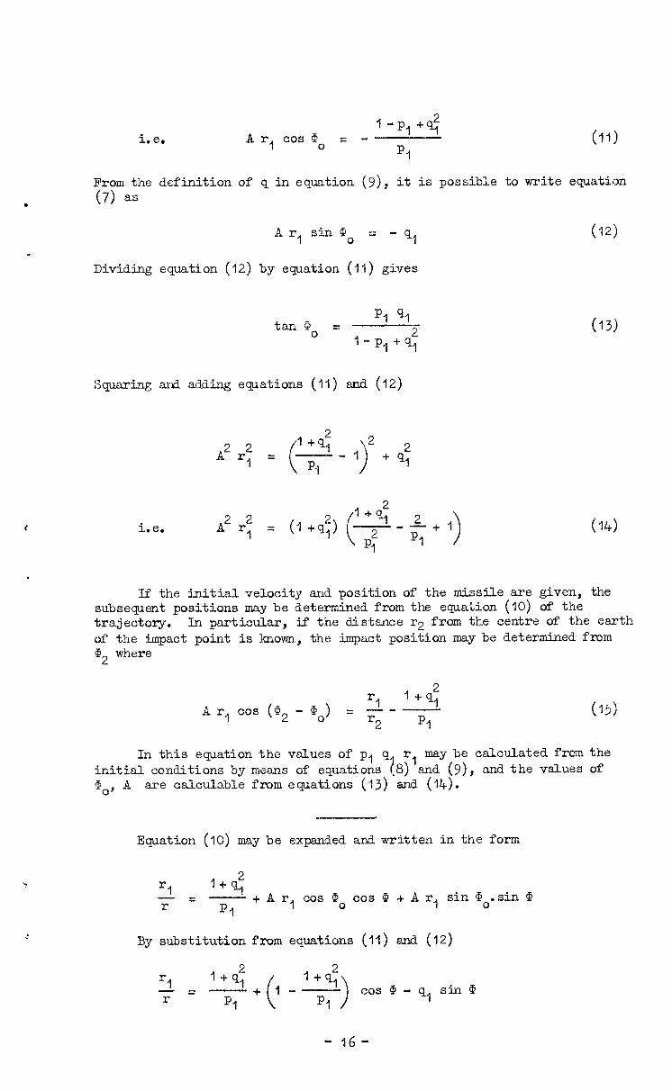
i.e, A r, co9 Go = - 1 -p,+q;
(11) p1
From the definition of q in equation (g), it is possible to write equation (7) as
Ar, sin ip = - q, 0
Dividing equation (12) by equation (11) gives
(12)
tar-ho = PI 91
I- Pj +qT
Squaring and adding equations (II) and (12)
(13)
i.e. A2 r* 1 = (l+q:) 04)
If the initial velocity and position of the missile are given, the subsequent positions may be determined from the equation (10) of the trajectory. In particular, if the distance r2 from the centre of the earth of the impact point is known, the impact position may be determined from 'fi2 where
rl A r, cos (G2 - Go) = - - - r2 PI
In this equation the values of p, q r, may be calculated from initial conditions by means of equations ,8 and (g), and the values i' > Qo, A are calculable from equations (13) and (14).
Equation (10) may be expanded and written in the form
“I 1 f q; r= -+Ar,~~~~~~os@+Ar,sin~~.sin@
PI
By substitution from equations (II) and (12)
(15)
the of
'I r=
$+(I -2) cod-q., sin@
- 16-
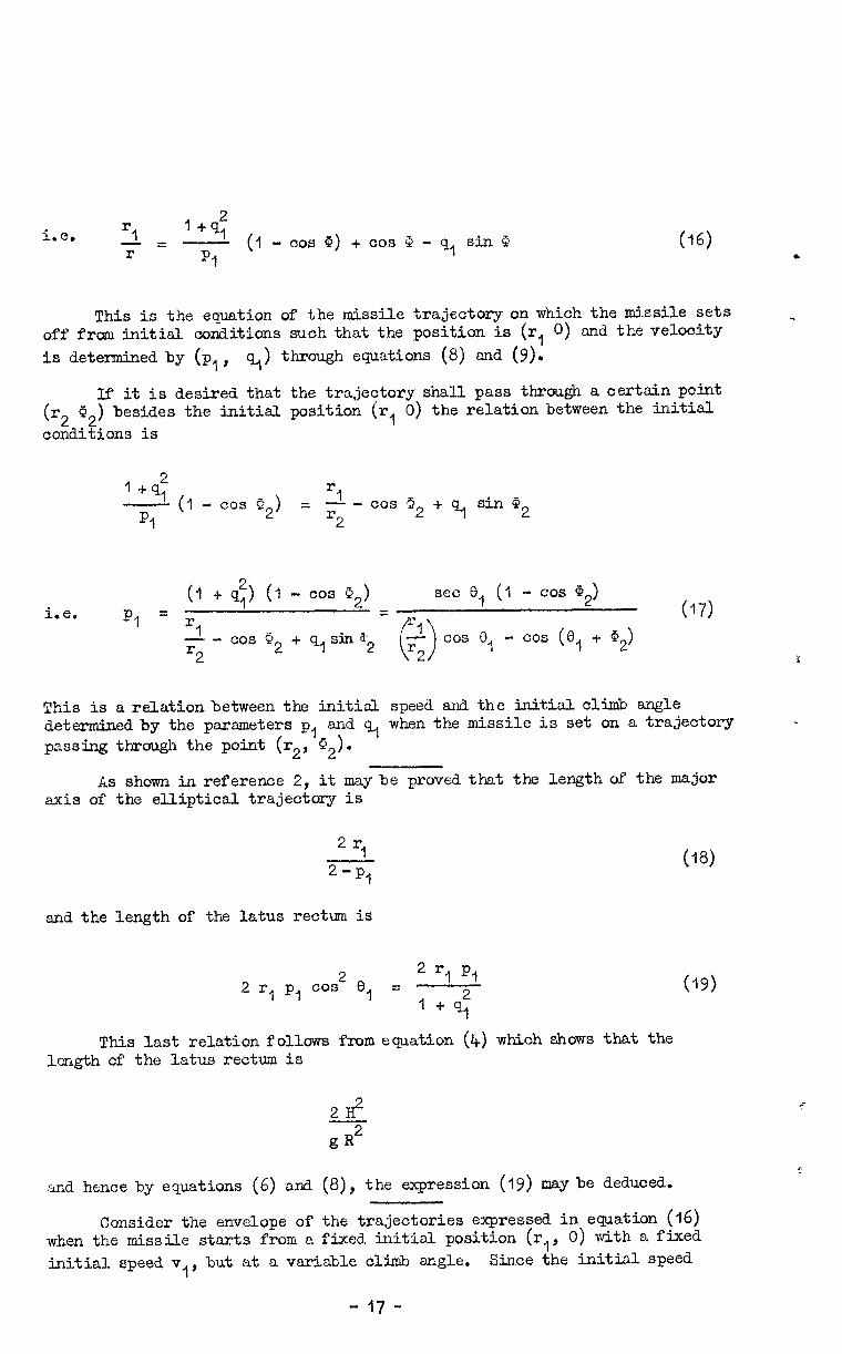
i.c, =I r
= z..$ (I- co-s 0) + CDS 3 - q, sin Q (16)
This is the eauation of the missile trajectory on which the missile sets off from initial conditions such that the position is (r, 0) and the velocity is determined by (p,' q-,) through equations (8) and (9).
If it is desired that the trajectory shall pass through a certain point (r2 02) besides the initial position (r, 0) the relation between the initial. conditions is
1 -N; - (1 - cos G2) = 2 - co9 3 2 c+ sin Q2 4.
PI r2
(1 + q;) (1 - cos 02) set 0, (I - cos a2) i.e. p1 = r, =*
3 (17)
- - cos P2 -k qlsin $2 cos 0 - r2 0 r2 I cos (0, + G2>
:
This is a relation between the initial speed and the initial. climb angle determined by the parameters pl and q, when the missile is set on a trajectory passing through the point (r2, G2).
,
As shown in reference 2, it maybe proved t-hat the length of the major axis of the elliptical trajectory is
2 “I 2;p1
and the length of the latus rectum is
2 rl p, 2f3, = 2 rl PI cos 1 + 9:
This last relation follows from equation (4) which shows that the length of the latus rectum is
2H2
g R2 and hence by equations (6) and (8), the expression (19) may be deduced.
(18)
(19)
Consider the envelope of the trajectories expressed in equation (16) when the missile starts from a fixed initial position (r,, 0) with a fixed initial speed v 1, but at a variable climb angle. Since the initial speed
- 17 -
t
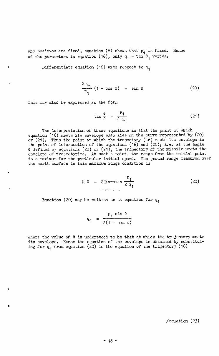
and position are fixed, equation (8) shows that p, is fixed. Hence of the parameters in equation (j6), only q, = tan 8, varies.
Differentiate equation (16) with respect to q,
2 91 - (1 - PI
cos tk) = sin @
This may also be expressed in the form
PI tan.5 = - 2 9,
(20)
cw
The interpretation of these equations is that the point at which equation (16) meets its envelope also lies on the curve represented by (20) or (21). Thus the point at which the trajectory (16) meets its envelope is the point of intersection of the equations (16) and (20); i.e. at the angle (I, defined by equations (20) or (21), the trajectory cf the missile meets the envelcpe of trajectories. At such a point, the ?%nge from the initial point is a maximum for the particular initial speed. The ground range measured over the earth surface in this maximum range condition is
V
KG PI = 2RarctmT-
(22)
Equation (20) may be written as an equation for q,
p, sin G
q1 = 2(q - cos 0)
where the value of Q is understood to be that at which the trajectory meets its envelope. Hence the equation of the enveLope is obtained by substitut- ing for q, from equation (20) in the equation of the trajectory (16)
/equation (23)
- 18 -
Since
rl - cos @ p: sin' d -= Jl 1 Ii-
c - 00s Q2 3 * cos a -
p, sin2 @
r p-l 40 2(-l - cos a)
. . .
i.e.
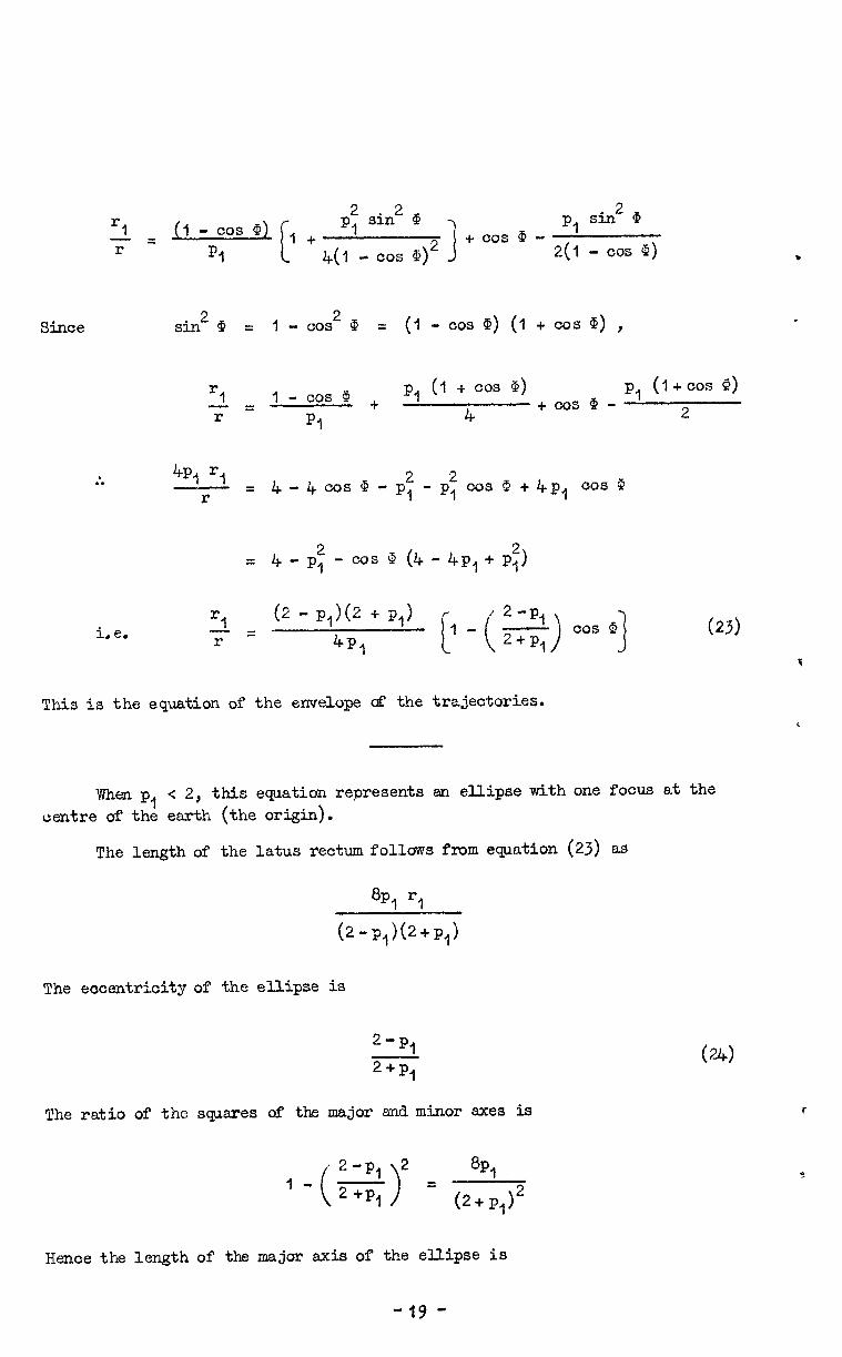
sin2 Q = 1 - cos 2a = (l- cos 9) (1 + cos G) ,
2 I - cos 9 + p, (1 + cos Q) p, (l+cos Q) =
r 4 +costl?-
pj 2
43 5 2 r
= 4-4cosI-p,-p~cosP+4p, cos c?
= 4 - p: - cos 9 (4 - 4P, + Pi,
3 (2 - P,)@ + P,> r = 4p-l
p -(g$ cos q (23)
This is the equation of the envelope uf the trajectories.
W&n p, < 2, this equation represents an ellipse with one focus at the centre of the earth (the origin).
The length of the latus rectum follows from equation (23) as
8pl 'I
@-P+-P,)
The eccentricity of the ellipse is
2-P, 2+p1
The ratio of the sqsres of the major and minor axes is
2-P, 2 ?- - ( > 8pl
2 'Pj = t2+PlJ2
(W
Hence the length of the major axis of the ellipse is
-19 -
.
.
8pl 5 (2+q12 2+P,'
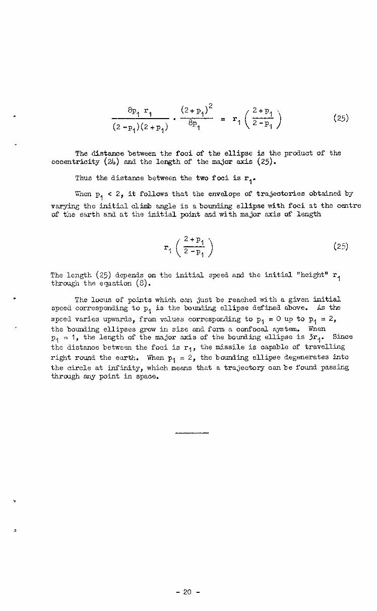
(2.p,)(2+p,) l 8q = r1 2-pl ( J (25)
The distance between the foci of the ellipse is the product of the eccentricity (24) and the length of the major axis (25).
Thus the distance between the two foci is r,'
Vhen p, < 2, it follows that the envelope of trajectories obtained by varying the initial cli& angle is abounding ellipse with foci at the centre of tne earth and at the initial point and with major axis of length
2+P,' rj - ( J 2 -PI (25)
The length (25) depends on the initial speed and the initial "height" r, through the equation (8).
The locus of points which can just be reached with a given initial speed corresponding to p, is the bounding ellipse defined above. As the speed varies upwards, from values corresponding to pl = 0 up to p, = 2, the bounding ellipses grow in size and form a confocal system. When PA = 1, the length of the major axis of the bourding ellipse is 3r,. Since
the distance between the foci is rl, the missile is capable of travelling right round the earth. When p1 = 2, the bounding ellipse degenerates into the circle at infinity, which means that a trajectory canbe found passing through any point in space.
- 20 -
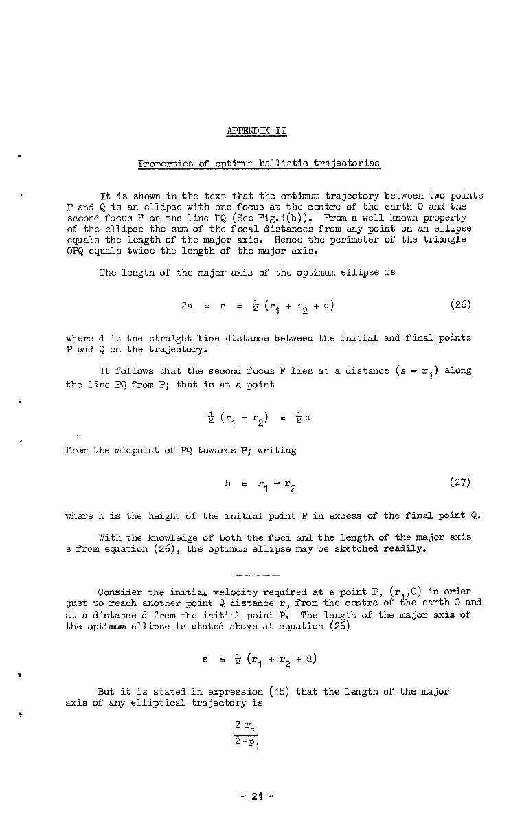
APPENDIX11
Properties of optimum ballistic trajectories
It is shown in the text that the optimum trajectory between two points P and Q is an ellipse with one focus at the centre of the earth 0 and the second focus F on the line PQ (See Fig.l(b)). From a well known property of the ellipse the sum of the focal distances from any point on an ellipse equals the length of the major axis. Hence the perimeter of the triangle OPQ equals twice the length of the major axis.
The length of the major axis of the optimum ellipse is
2a = s = 4 (r, + r2 + d) (26)
where d is the straight line distance between the initial and final points P and Q on the trajectory.
It follows that the second focus F lies at a distsnce (s - r,) along the line PQ from P; that is at a point
3 (r, - r2) = &h
from the midpoint of PQ towards P; writing
h = r, - r2 (27)
where h is the height of the initial point P in excess of the final point Q.
With the knowledge of both the foci and the length of the major axis s from equation (26), the optimum ellipse maybe sketched readily.
Consider the initial velocity required at a point P, (rA,O) in order just to reach another point Q distance r2 from the centre of the earth 0 and at a distance d from the initial point P. The length of the major axis of the optimum ellipse is stated above at equation (26)
S = 4- (r , +r2+a)
But it is stated in expression (18) that the length cf the major axis of any elliptical trajectory is
- 23 -
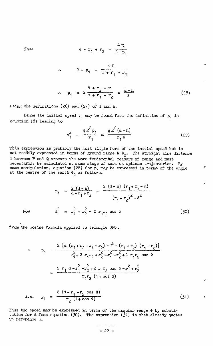
Thus 4 “1 d+r,+r2 = - 2-P,
. ““1 . . 2-p, = d + r, + r2
. d + r2 - r, d-h . . P, = 2 d+rl+r2 =T (28)
using the definitions (26) and (27) of d and h.
Hence the initial speed v, may be found from the definition of p,, in equation (8) leading to
2 gR2p1 gR2(d-h)
v1 = '1 = rs (29) 1
This expression is probably the most simple form of the initial speed but is not readily expressed in terms of ground range R CD2. The straight line distance d between F and Q appears the more fundsmentsl measure of rsnge and must necessarily be calculated at some stage of vark on optimum trajectories. By some manipulation, equation (28) for p may be expressed in terms of the angle T at the centre of the earth Q 2 as follo&.
c
P, = 2 = 2 (d-h) +r2-4
d+rl+r2 (r, + r2) 2-d2
Now d2=: ; r +r - 2 rlr2 cos @ (30)
from the cosine formula applied to triangle OPQ.
2 id ( 2-( :. r,+r2+r,-r2)-d
P, = r, +r2) (r, -,>I
2 2 2 2 r,+ 2 r,r2 +r2 -r, -r2 +2 rlr2 cos 9
2 2 r,
d-r: -r2
+2 r,r2
cos P-r,+r 2 2 2 =
rlr2 (I+ cos 0) f
i.e. P, = 2 (d-rl+r2 cos 'P)
r2 (I+ cos 0) (31) 3
Thus the speed maybe expressed in terms of the angular range ip by substi- tution for d from equation (30). The expression (31) is that slready quoted in reference 3.
- 22 -
t
*
The value of the initial speed may also be found from the geometry of the bounding ellipse. Since it is required to just reach the point Q from the initial point 1, the bounding ellipse about the point P must pass throu@l Q. The sum of the distanoes from any point on an ellipse to the two foci equals the length of the major axis. Since 0 and P are foci of the bounding ellipse which passes through Q, the length of the major axis of the bounding ellipse must equal OQ + PQ. Thus from expression (25)
= r2+d (32)
i.e. p = 2 d-r,+r2
d+r,+r2
which agrees with equation (28) above.
The direction of the to just reach o. point Q is PQ an3 the upwe verticz?1 the horizontal at P be 6,.
initial velocity from a point P which suffices shown in the main text to bisect the angle between at P. Let the inclination of the trajectory to , Then it follows that in the triangle OPQ, the
angle OPQ = 2 8,. Iience by the sine formula applied to triangle OPQ,
:.
r2 rl sin2 8, = sin (2 6, + Q2)
(33) r2 sin Q
tan2 8, = 2 r, - r2 c0s Q '2
This expresses the initial dli.r& angle 8, directly in terms of the angular range G2.
It may perhaps be more convenient to express &the direction of the initial velocity in terms of the distance PQ = d. This may be aocom@ished as follows.
Prom the cosine formula applied in triangle OPQ, 2
cos 2 8, = r, + d2 - r2 2
2r Id
Adding unity to both sides of the equation gives
2 oos2 0, = (5 + d)2 - r$ 2 r,d
. . .
i.e.
2 (r, + d - r2) b, + d + r2) cos 0, =
4 r, d
cos 20, = s (d + h) 2 r,d
- 23 -
04
(35)
Similarly by subtracting both sides of equation (34) from unity
Sin ;!e, = b-2 - r, + d) (r2 + rj - d)
4 r, d
i.e. sin 28, = 1 S- d) (d-h) 2 r, d
Dividing equation (36) by (35) gives
(36)
(37)
This expresses the initial climb angle 0, in terms of the distance PQ = d and the "heights" r, and r2 by way of equations (26) and (27).
--
The optimum trajectory is completely determined by the positions of the two foci 0 aSiF and the length of the ma,jor axis s, from equation (26). Other quantities may be expressed readily in terms of known distances by standard properties of the pure and analytical geometry cf the ellipse.
From expression (ly), the length of the latus rectum is
2 r, p, cos 2 5
and so by equations (28) and (35) equals
d-h 2rl -ii-- ( > s (d+hl
2 r,d
zz z-h2 d h2 d = -d (38)
The ratio of the squares of the minor and major axes is equal to the ratio of the latus rectum to the major axis and from expression (38) this equals
d2-h2 sd
where s is given by (26).
It follows that the eccentricity of the optimum ellipse is
d2-h2 ,& \ sd / (39)
t
The equation of the optimum ellipse I~ be derived from equation (16) by substitution for p-, and q, from equations (28) and (37). Since the length of the latus rectum has been deduced already as expression (381, the equation of the ellipse may be Jvritten down readily as
7 2d r, -= r d2"h2 0 - cos 0) -I- cos (31 (40)
The speed at a general point on the optimum trajectory majjr be deduoed as follows. The length of' the major axis is given by expressions (18) and &so by (26) leading to the equation
2;: s--p tS
Thus (4-j >
at any general point on the optimum trajectory, and so it follows from the definition of p in equation (8) that
v2 2 1-1 = 2gR r s c ) h-2)
where v is the speed at any point in the trajectory. The distance r may be determined in terms of ground range by equation (40).
Under the initial conditions, when r = r, the fomula gives the speed t v as 1
2 2m2 b-r,) vl = r s 1
which agrees with the value already derived at eqation (29) since it follows from the definition (26) cf s that
2 6 -r,) = d-h (43)
The climb angle at a general point on the optimum trajectory may be derived . 221 various ways. The following method is probably the most direct. From equation (3)) the horizontal component of the velocity at any point is
v COS 8 = ri? = H r
From equation (5), the vertical component of the velocity at any point is
v sin 8 = ; = HAsin (3 - 9o)
- 25 -
Dividing these two equations to elininate v gives
tan 6 = Ar sin (Q - "o) L4-4) 9
The particular form of this equation when @ = 0 has been used already in equation (7). Equation (44) may b e expan?ied into the fonri
tan0 = r [ A cos (PO. sin rJ, - A sin 50.ccs $1
Comparison of equations (10) and (L&J) shows that
and
A COB Ii0 = :- - 2d 1 d2-h2
(45)
(46)
Substitution of equations (45) and (46) into (44) gives t
from which the dependence of 8 on 6 may be deduced by substitution for r from equation (40).
Expression (47) may be expressed in a simpler form which may not be convenient for accurate computing. Thus from equnticn (10)
1 I + q: -= Ar np, r,
$ cos (Q - Go) (1+3)
But from the form of equation (IO), the constant A must be the quotient cf the eccentricity of the ellipse and the semi-latus rectum which has length
PI I-1 -. Hence it follows that
where e is the eccentricity of the ellipse.
- 26 -
3
Now an expression for the eccentricity was derived as expression (39). Thus equation (4.8) leads to
1 z=
+ cos (e-Q
3ibstituting for kk from ewation (49) into (w+> gives
tan0 = sin (3 - Qo)
(I - d2;;2)-$ $ COS (&. ‘PO)
(49)
(50)
A value for Q. may he derived by division of equations (46) and (45) giving
tanQ [qg$q’ =
0 23 r,
d2-h2 - '
(51)
of h.
e-try of the relations, the velocity at impact which is governed may be found by interchanging r, and r2 i.e. reversing the sign
Hence from equation (28)
d+h P2 = Is"l
and from equation (37)
(52)
(53)
According to the sign convention used in references I and 2, the angle of climb 8 is taken positive before apogee is reached, c?nd negative from the apogee onwards. Thus in ecyuat;ion (37) the positive square z-cot is required for q, but in equation (53) the negative square rcct siiouid be taken for 92.
It may be observed that from equation (21)
/equation
- 27 -
*2 = -- 2s -2
(40)? It follows frm syx-metry that the equation of the trajectory, equation may also be written as
r2 2d r2 c y-= d2 h2 t --A
l- cas (Q2-@)
9
c
f + cas (4,-Q) - [+fy#Jf sin (@2-G) (54) =
The preceding formulae have been developed in a fom suitable when the initial and final points P and Q are given. They inay be summxized as follows.
The optimm trajectory is an ellipse with one focus at the centre of the earth and the other on the join PQ at a distmce & (d-h) from P.
Here d is the distance PQ and h = r? - r2,
The length of the major axis of the ellipse is
S = 4 Cr , + r2 f d) by equaticn (26)
The speed v at a general point cn the b-3 as
trajectory is given by equaticn
J = ZgR2 CL.? \ > r s
The initial speed is v, where E
2 9 =
eR2 (d-h) r, s by equation (25)
which rmy be expressed more directly in terms of the angular range @ as equation (31).
- 28 -
The climb angle 0 at a general point on the trajectory is given by either equation (47) or eption (rO)*
The climb angle at cut-off 0, is given by equation (37) as
tan2 e, = (s-a)(&-h) s (d+h)
which may be expressed in terms of the angular range @2 in equation (33) &S
r tan 2ej = "r -",
sin !I? 2 12 CWS a 2
Corresponding . values at impact may be derived by interehangzing 'I ana r 2
and changing the sign of h.
-I__
Similar formulae may be developed to show the range covered from a given set of initial conditions; from the position (r,,O) and the velocity governed by (p,, q,) which is assumed to be optimum.
By equation (32), the distance ?Q v:kiich can be covered is
(55)
This equation effectively determines the .ma;cimum range. The variation of speed cJ..kib angle and height along the trajeotory may be deduced by substituting the value of d given by equation (55) in the formulae developed above.
The angular range about the centre of the earth may be determined explioitly. By re-arrangement of equation (30),
C8S G2 = r: + r$ - d2
2r, r2
Thus d2 - (r4 - r2)2
('I + r2)2 - d*
Eliminate d by substitution from equation (.%),
/equation
- 29 -
tan2
2pl 47 - 2(2-P,) r2 = 4 2(2- p,) - r2 2p&--
i.e. -h-l 2;-g2 PI rl - '2 + 4 p, r2 = 2.
r-y%, + r7 2 (56)
The direction in whic=h a certsi~ speed dsnJtod by p, ,Qmu&l be d&@&&l so as to give nsxbnxxn range is most easily dstermined from equation (21).
and by equation (56) th is may be expressed in terns of p,, r, arx r2 by
tm 6, = 2 )-- .L ~ -- r2 - 3 P, bq + r2) -&
2 c P, r, - r2 f 4 q r2 i
i f-4 rr, - 2 _. I.3 i.e. tanel = '2pj. f -r 1 (‘1 +r2) 3
i 1 2 + -2 P, r2 3 (57)
- 30 -
APPJ3.XDl.X III ---
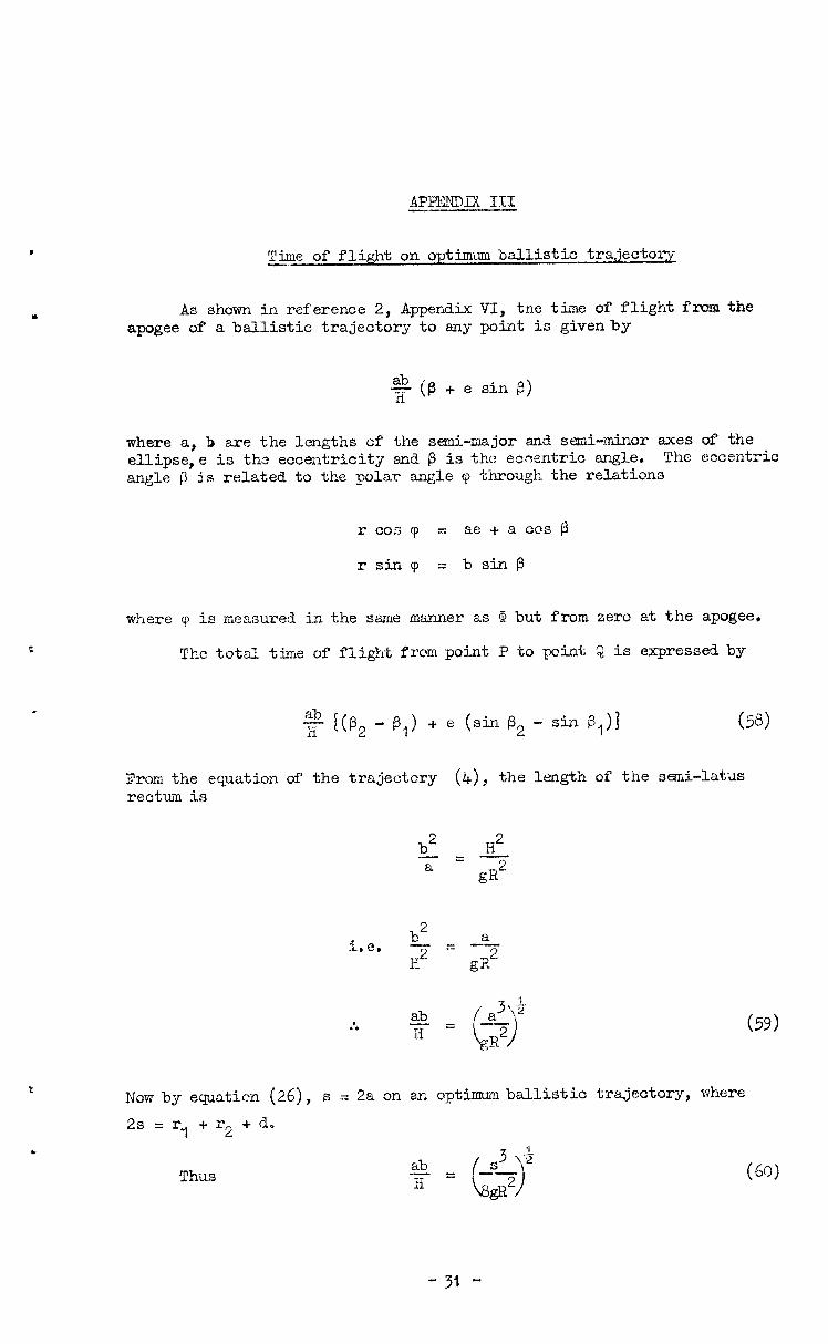
Time of flight on optima ballistic trajectory -
As shown in reference 2, Appendix VI, the time of flight fm the apogee of a ballistic trajectory to any point is givenby
?g (#3 + e sin P)
where a, b are the lengths of the semi-major end semi-minor axes of the ellipse,e is thu? eccentricity and 0 is tha ecoentric angle. The eccentric angle p is related to the polar engle v through the relations
rcoscp = ae + a cm @
r sin cp =bsinp
where 'p is measured in the shale manner as F! but from zero at the apogee.
The total time of flight from point P to paint Q is expressed by
From the equation of the trajectcry (4), the length of the sEslii.-latus rectuii is
b2 Hz I-=- a gR2
i.e.
ab a3 \5 :. -z-z ii 6) ,R2
Now by equal&n (26), s = 2a on en optimum ballistic trajectory, where
2s 7 =r fr 2 + d,
(59)
Thus
-31 -
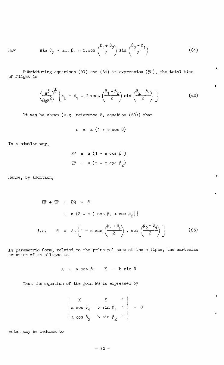
Now Sin 9, - sin P, = 2.COS i
P,+<, sin 9, - B,j
\ 2 i ( 2 j
Substituting equations (60) and (61) in eqression (5&), the total time of flight is
It may be shown (e.g. reference 2, equation 60)) that
r = a (1 + e cos P)
In a similar way,
PI? = a (I - e cos (3,)
QF = a (1 - e cos p,)
Iience, by addition,
= a (2 - e ( cos P, + GOS P,) ]
i.e. d = - e cos ("'l"'> . cos (e2LB,) ] (63)
In parametric form, related to the principal axes of the ellipse, the cartesian equation of an ellipse is
X = a cos p; Y =bsi.np
Thus the equation of the join PQ is expressed by
x Y I
a cos 9 1 b sin p, 1 I j a CDS p, b sin 8, I
= 0
which may be reduced to
- 32 -
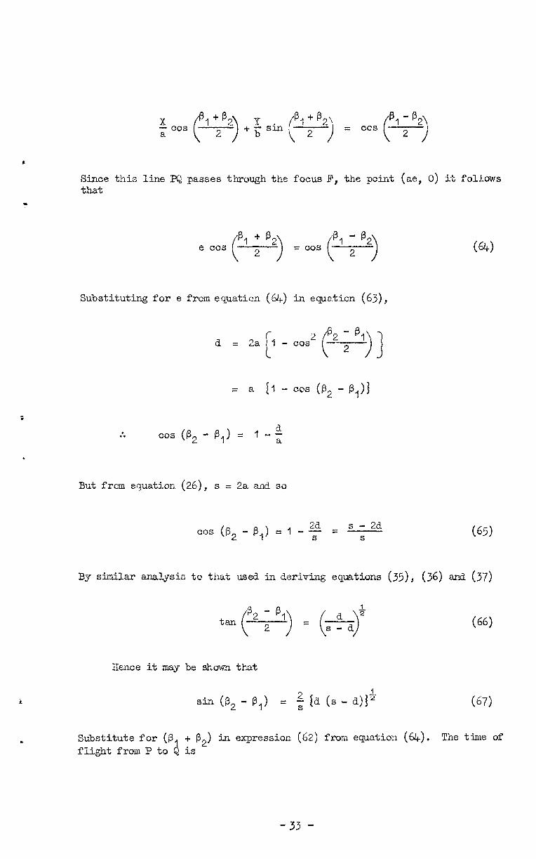
Since this line PQ passes through the focus P, the point (a@, 0) it follows that
e cm (PI 1”) = cos $I ; “‘>
Substituting for e from equaticn (64) in ewatic;n (63),
d = 2a [, - cos2 (%g!i) ]
z a El - ~0s (P, - PII3
t
:. cos (P2 -p,)= 1-t
But from equation (26), s = 2a and so
cos (p, - p,) = 1 - $ = s ; 2d
W-1
(65)
By similar analysis to that used in deriving equations (35), (36) and (37)
(66)
Hence it may be shcwn that
sin (B2 - PI) = $ {ii (s - d)+ (67)
Substitute for (9 flight from P to a
+ @2) in expression (62) from equation (64). The tinie of is
-33 -
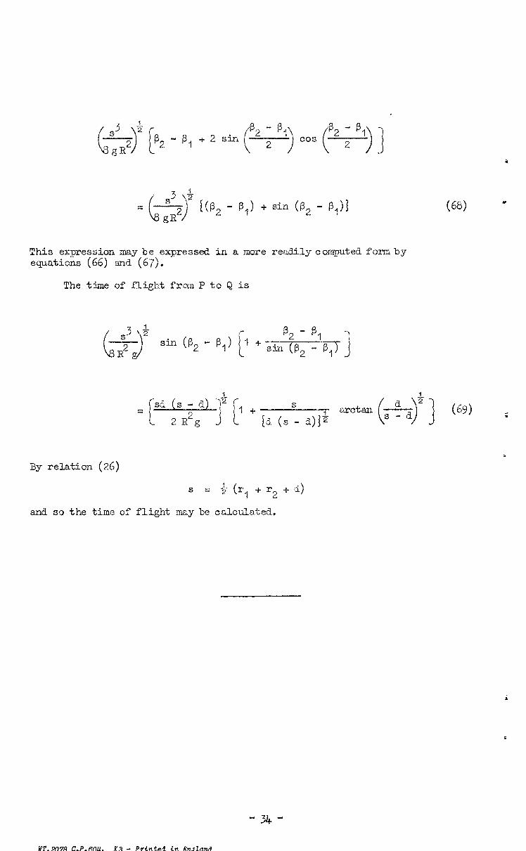
This expression may be expressed in a more readUy computed formby equations (66) and (67).
The time of flight from P to Q is
r sa = c ( s-d -)2f
2 R2g J i 1 -I- s [a (s - a)+
arctan (f-+)+ ] (69) ;
By relation (26)
S = $ (r I + r2 + d)
and so the time of flight may be calculated.
-34-
WI’. 2078 C.P.604. K3 - PTinted in h’ndland
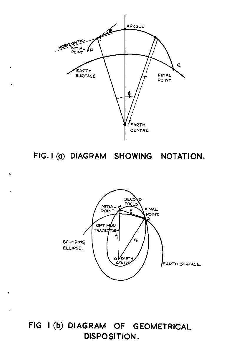
FIG. I (a) DlAGRAtwl SHOWING NOTATION.
/
BOUNOIN~
ELLIPSE,
ARTH SURFACE.
FIG I (b) DIAGRAM OF GEOMETRICAL DISPOSITION.
25
20
I5
JO
5
VALUES ON CURVIES DENOTE IMPACT RANG& IN NAUTICAL MILFc.
lOuJ 4000 5000 GROUND RANGE FROM CUT- OFF (NAUTICAL MILES) -
FIG. 2. SPEED ALONG TRAJECTORIES PLOTTED AGAINST GROUND RANGE CUT-OFF AT 100 No MILES HIGH.
I h d f, l *
VALUES ON CURVES DENOTE IMPACT RANGE IN NAUTICAL MILES.
24
22
20
18
16 SPEED ALONG,
TRAJECTORY (K FT./Xc;
I4
I2
6 0*2 0.4 0.6 04
FRACTION of IMPACT RANGE AL~N~ TRAJECTORY:
5500
5000
4500
4000
3500
3000
2500
2000
1500
1000
500
FIG. 3. SPEED ALONG TRAJECTORIES FOR CUT-OFF AT 100 N. MILES HIGH.
40
30
20 ~
~
IO
0
-10
- 20
-30
-4c
-5C
VALUES ON CURVES -DENOTE IMPACT RANGE
IN NAUTICAL MILES.
600
1000
500
FRACTION 0F IMPACT RANGE ALONG TRAmToRY +
5500 5000 4500
~ 4000 ~ 3500
~ 3000 2500 2000
FI G. 4, VARIATION OF CLI MB ANGLE ALONG TRAJECTORY FOR CUT-OFF 100 MMILES HIGH.
EXPRESSED IN RELATION TO LOCAL HORIZONTAL.
LIM8 ANG,LE (DQREES)
C
i
A
33
32 0
HElqHT OF CUT- OFF POINT. (N. MILES> -
m INCLINATION OF CUT OFF CLIMB ANGLE TO HORIZONTAL.
CUT-OFF SPEED
(K.FT/sEc)
18*0
0
HEIGHT OF CUT -OFF POINT (N. MILES) -
a SPEED AT CUT- OFF.
I 34
1240
I I220
FLIGHT TIME
(SECSJ
1200
i II80
IO HEIGHT OF CUT-OFF POINT (N,MILES) -
F 0 c TIME OF FLIGHT FROM CUT OFF TO IMPACT.
FIG 7. (a,b SC) VARIATION OF CUT-OFF VELOCITY AND FLIGHT TIME WITH HEIGHT OF CUT -OFF FOR IMPACT RANGE OF 2500 N. MILES.
16
6
4
VALUES ON CURVES DIZNOTtZ CUT-OFF HEIGHT IN NAUTICAL MILES.
.-A- -- -- -a-- P 1000 2000 3VW 4999 5uuu
IMPACT RA-C FROM CUT-OFF (NAUTICAL MILES) -
t
FIG. 8. VARIATION OF CUT-OFF SPEED WITH IMPACT RANGE FOR VARIOUS CUT-OFF
HEIGHTS.
\
0
50
T IO0 4 -VALUES OFJ CURVES -
DENOTE CUT -OFF HEIGHT IN NAUT\CAL MILES.
0 IO00 2000 3000 4000 5000 \MPACT RANGE FROM CUT- OFF (N. M I LES) -
FIG. 9. VARIATION OF CUT-OFF CLIMB ANGLE WITH IMPACT RANGE FOR VARIOUS CUT-OFF
HEIGHTS.
1600
1400
600
z VAWES ON CURVES DENOTE HE\ CHT OF CUT-OFF IN NAUTICAL M I ES.
0 IO00 2000 3000 4000 5000
IMPACT RANGE FROM CUT -OFF POINT (NAUTICAL MILES) -
FIG. IO. VARIATION OF TIME OF FLIGHT FROM CUT-OFF TO IMPACT WITH RANGE TO IMPACT.
C.P. No. 604
Q Crown Copyn’gt 1962
Published by HER MAJESTY’S STATIONERY OFFER
To be purchased from York House, Kingsway, London w.c.2
423 Oxford Street, London w.1 13~ Castle Street, Edinburgh 2
109 St. Mary Street, Cardiff 39 King Street, Manchester 2
50 Fairfax Street, Bristol- 1 35 Smallbrook, Ringway, Birmingham S
80 Chichester Street, Belfast 1 or through any bookseller
Printed in England
S.0, CODE No. 23-9013-4
C.P. No. 604