Embed Size (px)
Citation preview
Mobile 3D Vision3D Scene Reconstruction with a Trifocal View on a Mobile Device
Sebastian Otte · Ulrich Schwanecke · Peter Barth
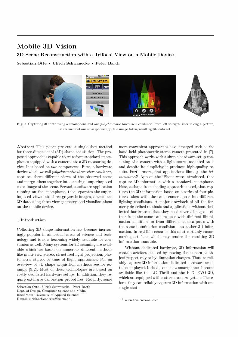
Fig. 1 Capturing 3D data using a smartphone and our polychromatic three-view combiner. From left to right: User taking a picture,
main menu of our smartphone app, the image taken, resulting 3D data set.
Abstract This paper presents a single-shot method
for three-dimensional (3D) shape acquisition. The pro-
posed approach is capable to transform standard smart-
phones equipped with a camera into a 3D measuring de-
vice. It is based on two components. First, a hardware
device which we call polychromatic three-view combiner,
captures three different views of the observed scene
and merges them together into one single superimposed
color-image of the scene. Second, a software application
running on the smartphone, that separates the super-
imposed views into three greyscale-images, determines
3D data using three-view geometry, and visualizes them
on the mobile device.
1 Introduction
Collecting 3D shape information has become increas-
ingly popular in almost all areas of science and tech-
nology and is now becoming widely available for con-
sumers as well. Many systems for 3D scanning are avail-
able which are based on numerous different methods
like multi-view stereo, structured light projection, pho-
tometric stereo, or time of flight approaches. For an
overview of 3D shape acquisition methods see for ex-
ample [9,2]. Most of these technologies are based on
costly dedicated hardware setups. In addition, they re-
quire extensive calibration procedures. Recently, some
Sebastian Otte · Ulrich Schwanecke · Peter Barth
Dept. of Design, Computer Science and Media
RheinMain University of Applied SciencesE-mail: [email protected]
more convenient approaches have emerged such as the
hand-held photometric stereo camera presented in [7].
This approach works with a simple hardware setup con-
sisting of a camera with a light source mounted on it
and despite its simplicity it produces high-quality re-
sults. Furthermore, first applications like e.g. the tri-
mensional1 App on the iPhone were introduced, that
capture 3D information with a standard smartphone.
Here, a shape from shading approach is used, that cap-
tures the 3D information based on a series of four pic-
tures taken with the same camera pose but different
lighting conditions. A major drawback of all the for-
merly described methods and applications without ded-
icated hardware is that they need several images – ei-
ther from the same camera pose with different illumi-
nation conditions or from different camera poses with
the same illumination condition – to gather 3D infor-
mation. In real life scenarios this most certainly causes
moving artefacts which may render the resulting 3D
information unusable.
Without dedicated hardware, 3D information will
contain artefacts caused by moving the camera or ob-
ject respectively or by illumation changes. Thus, to reli-
ably capture 3D information dedicated hardware needs
to be employed. Indeed, some new smartphones become
available like the LG Thrill and the HTC EVO 3D,
which are equipped with a stereo camera system. There-
fore, they can reliably capture 3D information with one
single shot.
1 www.trimensional.com
2
In this paper, we present a single-shot method for
3D shape acquisition, that can be used with every smart-
phone having a standard camera. Our primary contri-
butions are first, a polychromatic three-view combiner
and second, a three view stereo algorithm, that deter-
mines 3D information out of images taken by using the
combiner. The method is made available through an
Android App, which captures images and then recon-
structs the 3D information about a scene.
2 Proposed method
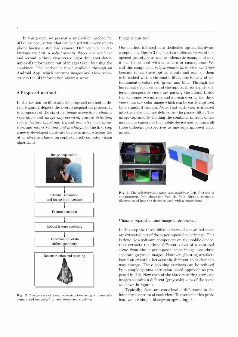
In this section we illustrate the proposed method in de-
tail. Figure 2 depicts the overall acquisition process. It
is composed of the six steps image acquisition, channel
separation and image improvement, feature detection,
robust feature matching, trifocal geometry determina-
tion, and reconstruction and meshing. For the first step
a newly developed hardware device is used, whereas the
other steps are based on sophisticated computer vision
algorithms.
Image acquisation
Channel separationand image improvement
Feature detection
Robust feature matching
Determination of the trifocal geometry
Reconstruction and meshing
Fig. 2 The process of scene reconstruction using a monocularcamera and our polychromatic three-view combiner.
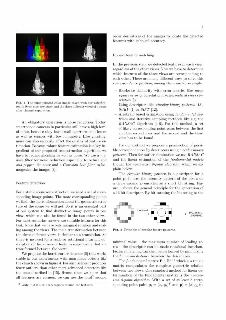
Image acquisition
Our method is based on a dedicated optical hardware
component. Figure 3 depicts two different views of our
opened prototype as well as schematic example of how
it has to be used with a camera or smartphone. We
call this component polychromatic three-view combiner
because it has three optical inputs and each of them
is furnished with a chromatic filter, one for any of the
fundamental colors red, green, and blue. Through the
horizontal displacement of the inputs, three slightly dif-
ferent perspective views are passing the filters. Inside
the combiner two mirrors and a prism overlay the three
views into one color image which can be easily captured
by a standard camera. Note, that each view is isolated
into the color channel defined by the passed filter. The
image captured by holding the combiner in front of the
monocular camera of the mobile device now contains all
three different perspectives as one superimposed color
image.
Fig. 3 The polychromatic three-view combiner. Left: Pictures ofour prototype from above and from the front. Right a schematic
illustration of how the device is used with a smartphone.
Channel separation and image improvement
In this step the three different views of a captured scene
are extracted out of the superimposed color image. This
is done by a software component on the mobile device,
that extracts the three different views of a captured
scene from the superimposed color image into three
separate greyscale images. However, ghosting artefacts
based on crosstalk between the different color channels
may emerge. These ghosting artefacts can be reduced
by a simple gamma correction based approach as pro-
posed in [10]. Now each of the three resulting greyscale
images contains a different (greyscale) view of the scene
as shown in figure 4.
Typically, there are considerable differences in the
intensity spectrum of each view. To overcome this prob-
lem, we use simple histogram spreading [3].
3
Fig. 4 The superimposed color image taken with our polychro-matic three-view combiner and the three different views of a scene
after channel separation.
An obligatory operation is noise reduction. Today,
smartphone cameras in particular still have a high level
of noise, because they have small apertures and lenses
as well as sensors with low luminosity. Like ghosting,
noise can also seriously affect the quality of feature es-
timation. Because robust feature estimation is a key in-
gredient of our proposed reconstruction algorithm, we
have to reduce ghosting as well as noise. We use a me-
dian filter for noise reduction especially to reduce salt
and pepper like noise and a Gaussian blur filter to ho-
mogenize the images [3].
Feature detection
For a stable scene reconstruction we need a set of corre-
sponding image points. The more corresponding points
we find, the more information about the geometric struc-
ture of the scene we will get. So it is an essential part
of our system to find distinctive image points in one
view, which can also be found in the two other views.
For most scenarios corners are suitable features for this
task. Note that we have only marginal rotation and scal-
ing among the views. The main transformation between
the three different views is similar to a translation. So
there is no need for a scale or rotational invariant de-
scription of the corners or features respectively that are
transformed between the views.
We propose the harris corner detector [5] that works
stable in our experiments with man made objects like
the church shown in figure 4. For such scenes it produces
fewer outliers than other more advanced detectors like
the ones described in [15]. Hence, since we know that
all features are corners, we can use the local2 second
2 Only in 3 × 3 or 5 × 5 regions around the features.
order derivatives of the images to locate the detected
features with subpixel accuracy.
Robust feature matching
In the previous step, we detected features in each view,
regardless of the other views. Now we have to determine
which features of the three views are corresponding to
each other. There are many different ways to solve this
correspondence problem, among them are for example:
– Blockwise similarity with error metrics like mean
square error or correlation like normalized cross cor-
relation [3].
– Using descriptors like circular binary patterns [13],
SURF [1] or SIFT [12].
– Algebraic based estimation using fundamental ma-
trices and iterative sampling methods like e.g. the
RANSAC algorithm [4,6]. For this method, a set
of likely corresponding point pairs between the first
and the second view and the second and the third
view has to be found.
For our method we propose a preselection of possi-
ble correspondences by descriptors using circular binary
patterns. Then for outlier elimination we use RANSAC
and the linear estimation of the fundamental matrix
though the normalized 8-point algorithm which we ex-
plain below.
The circular binary pattern is a descriptor for a
point p. It uses the intensity pattern of the pixels on
a circle around p encoded as a short bit string. Fig-
ure 5 shows the general principle for the generation of
a 16 bit descriptor. By bit-rotating the bit-string to the
threshold10011010......00101011
Fig. 5 Principle of circular binary patterns.
minimal value – the maximum number of leading ze-
ros – the descriptor can be made rotational invariant.
Feature matching can then be performed by minimizing
the hamming distance between the descriptors.
The fundamental matrix F ∈ R3×3 which is a rank 2
matrix encapsulates the complete geometric relation
between two views. One standard method for linear de-
termination of the fundamental matrix is the normal-
ized 8-point algorithm. With a set of at least 8 corre-
sponding point pairs pi = (xi, yi)T and p′i = (x′i, y
′i)
T ,
4
we can give a first linear approximation of the funda-
mental matrix F describing the geometry between two
different views of a scene (see [6]) by solving the homo-
geneous linear system
Af = 0 (1)
with
A =
x′1x1 x′1y1 x
′1 y′1x1 y′1y1 y
′1 x1 y1 1
......
......
......
......
...
x′nxn x′nyn x
′n y′nxn y
′nyn y
′n xn yn 1
subject to ‖f‖ = 1. The solution vector f is given as
the eigenvector assigned to the smallest eigenvalue of
A. It can be estimated by using singular value decom-
position (SVD) [14]. Thereby f contains the values of
F in row major order. Note that this F is not neces-
sarily singular. It is a common step forcing F to have
rank 2 by setting the smallest singular value in Σ where
UΣV = F is the singular value decomposition of F to
zero. This can somewhat increase the algebraic error of
F but can be shown to be in some kind the best possible
approximation having rank 2. For numerical stability
the points pi and p′i are normalized before solving the
linear system (1) so that their are centered around zero
and their mean distance to each other equals√
2.
In the following we describe the five steps of our
robust feature matching process between two different
views.
1. Find putative correspondences C using a harris cor-
ner detector and circular binary patterns.
2. Pick 8 correspondences (x,x′) from C and linearly
estimate the fundamental matrix F.
3. Identify inlier and outlier based on the algebraic
error of the epiloar constraint
x′TFx!= 0.
4. After a given number of iterations or sufficient num-
ber of inlier continue with step 5, otherwise go back
to step 2.
5. Reestimate F from all inlier and reselect correspon-
dence via algebraic error or the geometric backpro-
jection error [6].
Finally, we join the nondisjunct two-point corre-
spondences to three-point correspondences which we
now use for further computations.
It should be mentioned that there are several other
ways of feature matching. For example, one could match
three-point correspondence directly via algebraic error
minimization of the trifocal tensor (see next subsection)
or via geometric error minimization of the three-view
triangulated back-projections (for details see [6]).
Determination of the trifocal geometry
Our main goal is to reconstruct the real world points
X of the scene that was photographed. For this issue
we want to use the complete information of all three
different views, that means the complete three view ge-
ometry. This geometry can be described by the trifocal
tensor T which is a 3×3×3 tensor [6]. In the following
we use both matrix notation T = {T1,T2,T3} as well
as tensor notation3 T jki .
From the tensor T all three camera matrices P, P′,
and P′′ can be extracted as
P = [I | 0], (2)
P′ = [[T1,T2,T3]e′′ | e′], (3)
P′′ = [(e′′e′′T − I)[TT1 ,T
T2 ,T
T3 ]e′ | e′′], (4)
where e′, e′′ are the epipoles which also can be retrieved
from T . Note that the fundamental matrices between
the views also can be extracted from T (see [6]). The
world point X according to a given three-point corre-
spondence x ↔ x′ ↔ x′′ now can be determined by
solving the homogeneous system
AX = 0 with A =
x1pT3 − pT
1
x2pT3 − pT
2
x′1p′T3 − p′T1
x′2p′T3 − p′T2
x′′1p′′T3 − p′′T1x′′2p′′T3 − p′′T2
subject to ‖X‖ = 1. This system again can be efficiently
solved based on the SVD of A. Once more, the accu-
racy of the determined world point X can be improved
further with non-linear methods [6].However, before the computation begins the hard-
ware needs to be calibrated. We proprose both a manual
calibration as well as a more practical auto calibration.
The calibration was initially done manually with help
of the GML C++ Camera Calibration Toolbox 4. Based
on the three camera matrices P = [I | 0], P′ = [aij ], and
P′′ = [bij ] provided by the toolbox the trifocal tensor Tof the system can be calculated as
T jki = aji b
k4 − a
j4b
ki .
Note that manual calibration requires a static setup and
a calibration pattern. So already small variations of the
adapters position make it necessary to recalibrate the
system which is circuitous in practice. It is recommend
to auto-calibrate the system just from the scene infor-
mation.
3 Consider the equation y = Ax in tensor notation yi = aijxj
which is by convention a shorthand for yi =∑
j aijx
j .4 http://graphics.cs.msu.ru/en/science/research/calibration/cpp
5
For auto-calibration we compute a linear estimation
of T from n ≥ 7 (normalized) three-point correspon-
dences in a standard way (see [6]) as follows.
1. For each correspondence x ↔ x′ ↔ x′′ the condi-
tion
xk(x′ix′′lT 33k − x′′lT i3
k − x′iT 3lk + T il
k ) = 0
has to be fulfilled. With i, l ∈ {1, 2} we get four
linear independent equations per correspondence.
We now can combine these equations to a matrix
A ∈ R4n×27. Solving the linear system At = 0 sub-
ject to ‖t‖ = 1 gives t containing the 27 coefficients
of the initial estimation of the trifocal tensor T .
2. Retrieve the epipoles e′ and e′′ from the trifocal
tensor T as the common perpendicular to the left
null-vectors of T1,T2,T3.
3. Construct the matrix E ∈ R27×18 expressing the
linear relation T jki = ajie
′′k−e′jbki such that t = Ea
where t ∈ R27 is the vector of entries from T and
a representing the entries of the camera matrices
P′ = [aij ], and P′′ = [bij ] .
4. Minimize the function ‖AEa‖ subject to ‖Ea‖ = 1
to get a geometrical valid trifocal tensor5.
The desired camera matrices P,P′, and P′′ now can be
calculated from the determined trifocal tensor T using
equations (2)-(4).
It should be mentioned that there are also other
methods which can be used with our system. In [8] a
robust estimation of T based on genetic algorithms is
shown which outperforms traditional methods, like the
linear method described above. The method presented
in [11] which uses virtual parallax, provides a very fastcomputation of T by only a marginal loss in accuracy.
However, as a proof of concept in our actual system we
just implemented the described linear approximation
algorithm.
Reconstruction and meshing
As described above we determine the reconstruction X
out of each three-point correspondence x ↔ x′ ↔ x′′.
In case of auto calibration we can improve the recon-
struction results by using a simple gradient descent
method to minimize the geometric error
Eproj =∑i
(d(PXi,xi) + d(P′Xi,x′i) + d(P′′Xi,x
′′i )),
where d is an appropriate distance function. Here, we
simply use the euclidean distance as distance function.
5 In [6] a nonlinear improvement of the linear estimation is
proposed which is not yet implemented in our system.
The correction of each point Xi is now straightforward
and can be done by subtraction the gradient. This re-
sults in the iteration formula
Xi(t+ 1) = Xi(t)− α∂Eproj
∂Xi(t)
where α is a small weighting factor and t denotes the
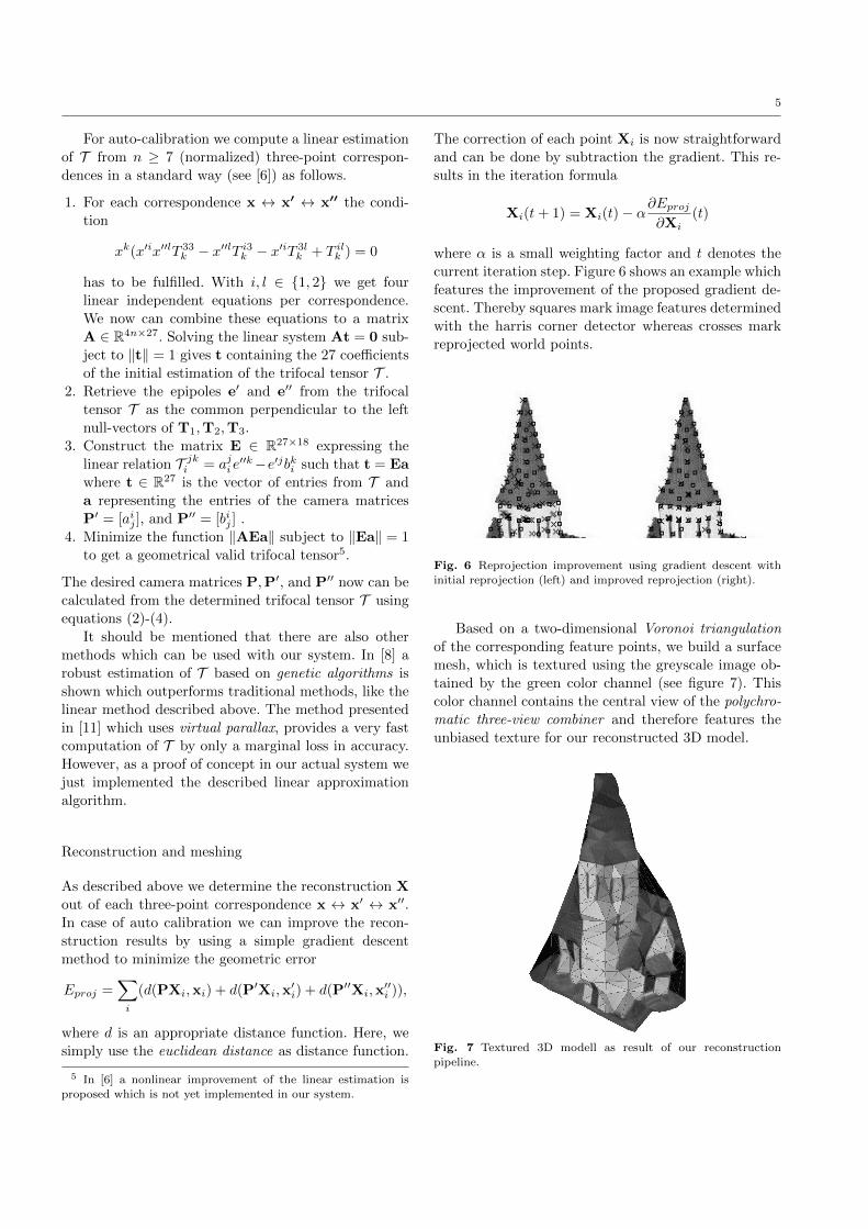
current iteration step. Figure 6 shows an example which
features the improvement of the proposed gradient de-
scent. Thereby squares mark image features determined
with the harris corner detector whereas crosses mark
reprojected world points.
Fig. 6 Reprojection improvement using gradient descent withinitial reprojection (left) and improved reprojection (right).
Based on a two-dimensional Voronoi triangulation
of the corresponding feature points, we build a surface
mesh, which is textured using the greyscale image ob-
tained by the green color channel (see figure 7). This
color channel contains the central view of the polychro-
matic three-view combiner and therefore features the
unbiased texture for our reconstructed 3D model.
Fig. 7 Textured 3D modell as result of our reconstruction
pipeline.
6
Implementation
The complete capturing and reconstruction system was
implemented in Java which makes it portable to run on
various kind of hardware systems. We implemented an
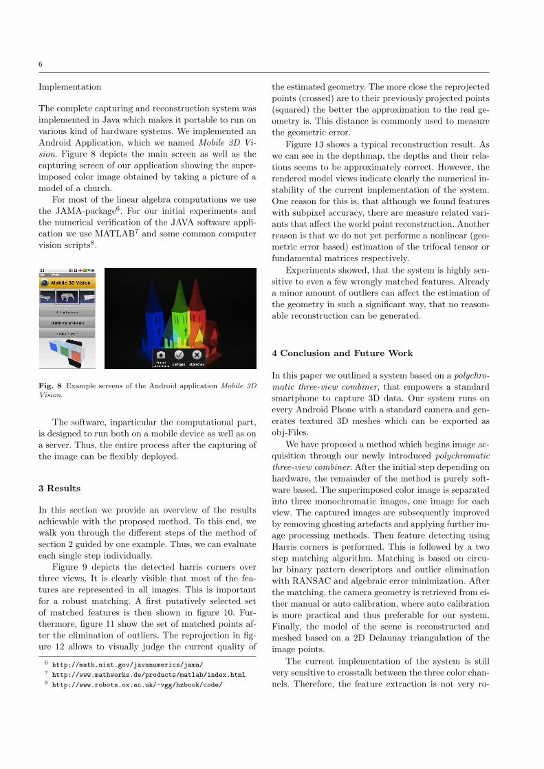
Android Application, which we named Mobile 3D Vi-
sion. Figure 8 depicts the main screen as well as the
capturing screen of our application showing the super-
imposed color image obtained by taking a picture of a
model of a church.
For most of the linear algebra computations we use
the JAMA-package6. For our initial experiments and
the numerical verification of the JAVA software appli-
cation we use MATLAB7 and some common computer
vision scripts8.
Fig. 8 Example screens of the Android application Mobile 3D
Vision.
The software, inparticular the computational part,
is designed to run both on a mobile device as well as on
a server. Thus, the entire process after the capturing of
the image can be flexibly deployed.
3 Results
In this section we provide an overview of the results
achievable with the proposed method. To this end, we
walk you through the different steps of the method of
section 2 guided by one example. Thus, we can evaluate
each single step individually.
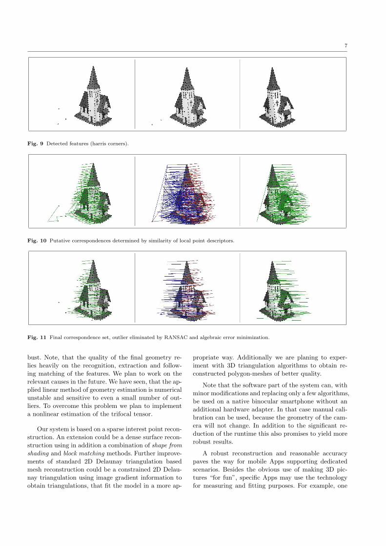
Figure 9 depicts the detected harris corners over
three views. It is clearly visible that most of the fea-
tures are represented in all images. This is important
for a robust matching. A first putatively selected set
of matched features is then shown in figure 10. Fur-
thermore, figure 11 show the set of matched points af-
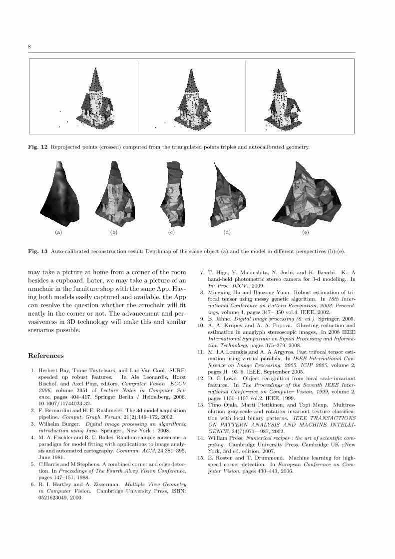
ter the elimination of outliers. The reprojection in fig-
ure 12 allows to visually judge the current quality of
6 http://math.nist.gov/javanumerics/jama/7 http://www.mathworks.de/products/matlab/index.html8 http://www.robots.ox.ac.uk/~vgg/hzbook/code/
the estimated geometry. The more close the reprojected
points (crossed) are to their previously projected points
(squared) the better the approximation to the real ge-
ometry is. This distance is commonly used to measure
the geometric error.
Figure 13 shows a typical reconstruction result. As
we can see in the depthmap, the depths and their rela-
tions seems to be approximately correct. However, the
rendered model views indicate clearly the numerical in-
stability of the current implementation of the system.
One reason for this is, that although we found features
with subpixel accuracy, there are measure related vari-
ants that affect the world point reconstruction. Another
reason is that we do not yet performe a nonlinear (geo-
metric error based) estimation of the trifocal tensor or
fundamental matrices respectively.
Experiments showed, that the system is highly sen-
sitive to even a few wrongly matched features. Already
a minor amount of outliers can affect the estimation of
the geometry in such a significant way, that no reason-
able reconstruction can be generated.
4 Conclusion and Future Work
In this paper we outlined a system based on a polychro-
matic three-view combiner, that empowers a standard
smartphone to capture 3D data. Our system runs on
every Android Phone with a standard camera and gen-
erates textured 3D meshes which can be exported as
obj-Files.
We have proposed a method which begins image ac-
quisition through our newly introduced polychromatic
three-view combiner. After the initial step depending on
hardware, the remainder of the method is purely soft-
ware based. The superimposed color image is separated
into three monochromatic images, one image for each
view. The captured images are subsequently improved
by removing ghosting artefacts and applying further im-
age processing methods. Then feature detecting using
Harris corners is performed. This is followed by a two
step matching algorithm. Matching is based on circu-
lar binary pattern descriptors and outlier elimination
with RANSAC and algebraic error minimization. After
the matching, the camera geometry is retrieved from ei-
ther manual or auto calibration, where auto calibration
is more practical and thus preferable for our system.
Finally, the model of the scene is reconstructed and
meshed based on a 2D Delaunay triangulation of the
image points.
The current implementation of the system is still
very sensitive to crosstalk between the three color chan-
nels. Therefore, the feature extraction is not very ro-
7
Fig. 9 Detected features (harris corners).
Fig. 10 Putative correspondences determined by similarity of local point descriptors.
Fig. 11 Final correspondence set, outlier eliminated by RANSAC and algebraic error minimization.
bust. Note, that the quality of the final geometry re-
lies heavily on the recognition, extraction and follow-
ing matching of the features. We plan to work on the
relevant causes in the future. We have seen, that the ap-
plied linear method of geometry estimation is numerical
unstable and sensitive to even a small number of out-
liers. To overcome this problem we plan to implement
a nonlinear estimation of the trifocal tensor.
Our system is based on a sparse interest point recon-
struction. An extension could be a dense surface recon-
struction using in addition a combination of shape from
shading and block matching methods. Further improve-
ments of standard 2D Delaunay triangulation based
mesh reconstruction could be a constrained 2D Delau-
nay triangulation using image gradient information to
obtain triangulations, that fit the model in a more ap-
propriate way. Additionally we are planing to exper-
iment with 3D triangulation algorithms to obtain re-
constructed polygon-meshes of better quality.
Note that the software part of the system can, with
minor modifications and replacing only a few algorithms,
be used on a native binocular smartphone without an
additional hardware adapter. In that case manual cali-
bration can be used, because the geometry of the cam-
era will not change. In addition to the significant re-
duction of the runtime this also promises to yield more
robust results.
A robust reconstruction and reasonable accuracy
paves the way for mobile Apps supporting dedicated
scenarios. Besides the obvious use of making 3D pic-
tures “for fun”, specific Apps may use the technology
for measuring and fitting purposes. For example, one
8
Fig. 12 Reprojected points (crossed) computed from the triangulated points triples and autocalibrated geometry.
(a) (b) (c) (d) (e)
Fig. 13 Auto-calibrated reconstruction result: Depthmap of the scene object (a) and the model in different perspectives (b)-(e).
may take a picture at home from a corner of the room
besides a cupboard. Later, we may take a picture of an
armchair in the furniture shop with the same App. Hav-
ing both models easily captured and available, the App
can resolve the question whether the armchair will fit
neatly in the corner or not. The advancement and per-
vasiveness in 3D technology will make this and similar
scenarios possible.
References
1. Herbert Bay, Tinne Tuytelaars, and Luc Van Gool. SURF:speeded up robust features. In Ale Leonardis, Horst
Bischof, and Axel Pinz, editors, Computer Vision ECCV
2006, volume 3951 of Lecture Notes in Computer Sci-ence, pages 404–417. Springer Berlin / Heidelberg, 2006.
10.1007/11744023 32.
2. F. Bernardini and H. E. Rushmeier. The 3d model acquisition
pipeline. Comput. Graph. Forum, 21(2):149–172, 2002.
3. Wilhelm Burger. Digital image processing an algorithmic
introduction using Java. Springer,, New York :, 2008.
4. M. A. Fischler and R. C. Bolles. Random sample consensus: aparadigm for model fitting with applications to image analy-sis and automated cartography. Commun. ACM, 24:381–395,June 1981.
5. C Harris and M Stephens. A combined corner and edge detec-
tion. In Proceedings of The Fourth Alvey Vision Conference,pages 147–151, 1988.
6. R. I. Hartley and A. Zisserman. Multiple View Geometryin Computer Vision. Cambridge University Press, ISBN:
0521623049, 2000.
7. T. Higo, Y. Matsushita, N. Joshi, and K. Ikeuchi. K.: A
hand-held photometric stereo camera for 3-d modeling. In
In: Proc. ICCV., 2009.8. Mingxing Hu and Baozong Yuan. Robust estimation of tri-
focal tensor using messy genetic algorithm. In 16th Inter-
national Conference on Pattern Recognition, 2002. Proceed-ings, volume 4, pages 347– 350 vol.4. IEEE, 2002.
9. B. Jahne. Digital image processing (6. ed.). Springer, 2005.
10. A. A. Krupev and A. A. Popova. Ghosting reduction andestimation in anaglyph stereoscopic images. In 2008 IEEEInternational Symposium on Signal Processing and Informa-tion Technology, pages 375–379, 2008.
11. M. I.A Lourakis and A. A Argyros. Fast trifocal tensor esti-
mation using virtual parallax. In IEEE International Con-ference on Image Processing, 2005. ICIP 2005, volume 2,
pages II– 93–6. IEEE, September 2005.
12. D. G Lowe. Object recognition from local scale-invariantfeatures. In The Proceedings of the Seventh IEEE Inter-
national Conference on Computer Vision, 1999, volume 2,pages 1150–1157 vol.2. IEEE, 1999.
13. Timo Ojala, Matti Pietikinen, and Topi Menp. Multires-
olution gray-scale and rotation invariant texture classifica-
tion with local binary patterns. IEEE TRANSACTIONSON PATTERN ANALYSIS AND MACHINE INTELLI-
GENCE, 24(7):971—987, 2002.14. William Press. Numerical recipes : the art of scientific com-
puting. Cambridge University Press, Cambridge UK ;;New
York, 3rd ed. edition, 2007.15. E. Rosten and T. Drummond. Machine learning for high-
speed corner detection. In European Conference on Com-
puter Vision, pages 430–443, 2006.


![State of Augmented Reality, Virtual Reality and Mixed Reality · State of Augmented Reality, Virtual Reality and Mixed Reality [Microsoft Hololen] [Ready Player One] Augmented Reality](https://img.pdfslide.net/doc/110x75/5f82ab6da2d89130b90d78c7/state-of-augmented-reality-virtual-reality-and-mixed-reality-state-of-augmented.jpg)