Embed Size (px)
Citation preview

Web: www.bonitron.com ● Tel: 615-244-2825 ● Email: [email protected]
Model M3713SC 3-Phase Power Supply
For 3-Phase Variable Frequency Drives
Customer Reference Manual

Bonitron, Inc.
2
Bonitron, Inc. Nashville, TN
An industry leader in providing solutions for AC drives.
ABOUT BONITRON
Bonitron designs and manufactures quality industrial electronics that improve the reliability of processes and variable frequency drives worldwide. With products in numerous industries, and an educated and experienced team of engineers, Bonitron has seen thousands of products engineered since 1962 and welcomes custom applications.
With engineering, production, and testing all in the same facility, Bonitron is able to ensure its products are of the utmost quality and ready to be applied to your application.
The Bonitron engineering team has the background and expertise necessary to design, develop, and manufacture the quality industrial electronic systems demanded in today’s market. A strong academic background supported by continuing education is complemented by many years of hands-on field experience. A clear advantage Bonitron has over many competitors is combined on-site engineering labs and manufacturing facilities, which allows the engineering team to have immediate access to testing and manufacturing. This not only saves time during prototype development, but also is essential to providing only the highest quality products.
The sales and marketing teams work closely with engineering to provide up-to-date information and provide remarkable customer support to make sure you receive the best solution for your application. Thanks to this combination of quality products and superior customer support, Bonitron has products installed in critical applications worldwide.
Bonitron, Inc.
3
AC DRIVE OPTIONS
In 1975, Bonitron began working with AC inverter drive specialists at synthetic fiber plants to develop speed control systems that could be interfaced with their plant process computers. Ever since, Bonitron has developed AC drive options that solve application issues associated with modern AC variable frequency drives and aid in reducing drive faults. Below is a sampling of Bonitron’s current product offering.
WORLD CLASS PRODUCTS
Undervoltage Solutions
Overvoltage Solutions
Uninterruptible Power for Drives (DC Bus Ride-Thru) Voltage Regulators
Chargers and Dischargers Energy Storage
Braking Transistors Braking Resistors
Transistor/Resistor Combo Line Regeneration
Dynamic Braking for Servo Drives
Common Bus Solutions
Portable Maintenance Solutions
Single Phase Power Supplies 3-Phase Power Supplies
Common Bus Diodes
Capacitor Formers
Capacitor Testers
Power Quality Solutions
Green Solutions
12 and 18 Pulse Kits
Line Regeneration
M3713SC
4
1. INTRODUCTION ..........................................................................................................................7 1.1. Who Should Use ........................................................................................................................... 7 1.2. Purpose and Scope ........................................................................................................................ 7 1.3. Manual Version and Change Record ............................................................................................ 7
Figure 1-1: Typical M3713SC 3-Phase Power Supply ............................................................................ 7 1.4. Symbol Conventions Used in this Manual and on Equipment ..................................................... 8
2. PRODUCT DESCRIPTION ............................................................................................................9 2.1. Related Products ........................................................................................................................... 9 2.2. Part Number Breakdown ............................................................................................................ 10
Figure 2-1: Example of Part Number Breakdown .................................................................................. 10 Table 2-1: Voltage Rating ...................................................................................................................... 10 Table 2-2: Current Ratings ..................................................................................................................... 10 Table 2-3: Chassis Style ......................................................................................................................... 11
2.3. General Specifications ................................................................................................................ 11 Table 2-4: General Specifications Chart ................................................................................................ 11
2.4. General Precautions and Safety Warnings ................................................................................. 12
3. INSTALLATION INSTRUCTIONS ................................................................................................13 3.1. Environment ............................................................................................................................... 13 3.2. Unpacking ................................................................................................................................... 13 3.3. Mounting .................................................................................................................................... 13
3.3.1. Mounting the M3713SC 3-Phase Power Supply ............................................................................. 13 Figure 3-1: M3713SC Mounting Orientation ......................................................................................... 13
3.4. Wiring and Customer Connections ............................................................................................. 14 3.4.1. Power Wiring .................................................................................................................................. 14
Table 3-1: Power Connection Specifications ......................................................................................... 14 3.4.2. I/O Wiring ....................................................................................................................................... 16
Table 3-2: I/O Wiring Specifications ..................................................................................................... 16 3.5. Typical Configurations ............................................................................................................... 17
Figure 3-2: M3713SC 3-Phase Power Supply Field Wiring Diagram (Single VFD) ............................. 17 Figure 3-3: M3713SC 3-Phase Power Supply Field Wiring Diagram (Multiple VFD) ......................... 18 Figure 3-4: M3713SC 3-Phase Power Supply Field with M3645 Regen Wiring Diagram .................... 19
3.6. Typical 12 Pulse Configurations ................................................................................................ 20 Figure 3-5: M3713SC 12-Pulse System ................................................................................................. 20 Figure 3-6: M3713SC 12-Pulse System with VFD ................................................................................ 20
3.7. Typical 18 Pulse Configurations ................................................................................................ 21 Figure 3-7: M3713SC 18-Pulse System ................................................................................................. 21 Figure 3-8: M3713SC 18-Pulse System with VFD ................................................................................ 22
4. OPERATION ..............................................................................................................................23 4.1. Functional Description ............................................................................................................... 23
4.1.1. Precharge......................................................................................................................................... 23 4.1.2. Operation......................................................................................................................................... 23
4.2. Features ....................................................................................................................................... 23 4.2.1. I/O – Inputs and Outputs ................................................................................................................. 23 4.2.2. Jumpers ........................................................................................................................................... 24
Figure 4-1: K7 and K10 Chassis Jumper 1 Location.............................................................................. 25 Figure 4-2: B5 Chassis Jumper 1 Location ............................................................................................ 25
4.2.3. Timing Chart ................................................................................................................................... 25 Figure 4-3: Typical Modes of Operation ................................................................................................ 25
4.2.4. External Indicators .......................................................................................................................... 26 4.2.5. Fault Modes .................................................................................................................................... 26
Table 4-1: Blink Patterns........................................................................................................................ 26

Table of Contents
5
4.3. Startup ......................................................................................................................................... 28 4.3.1. Pre-Power Checks ........................................................................................................................... 28 4.3.2. Startup Procedure and Checks ........................................................................................................ 28
Figure 4-4: Parallel Mode Interconnection............................................................................................. 29 Figure 4-5: Cascade Mode Interconnection ........................................................................................... 30
5. MAINTENANCE AND TROUBLESHOOTING ...............................................................................31 5.1. Periodic Testing .......................................................................................................................... 31 5.2. Maintenance Items ...................................................................................................................... 31 5.3. Troubleshooting .......................................................................................................................... 31
5.3.1. POWER indicator is not on ............................................................................................................. 31 5.3.2. Attached drive does not come on .................................................................................................... 31 5.3.3. STATUS indicator flashes .............................................................................................................. 32
5.4. Technical Help – Before you call ............................................................................................... 33
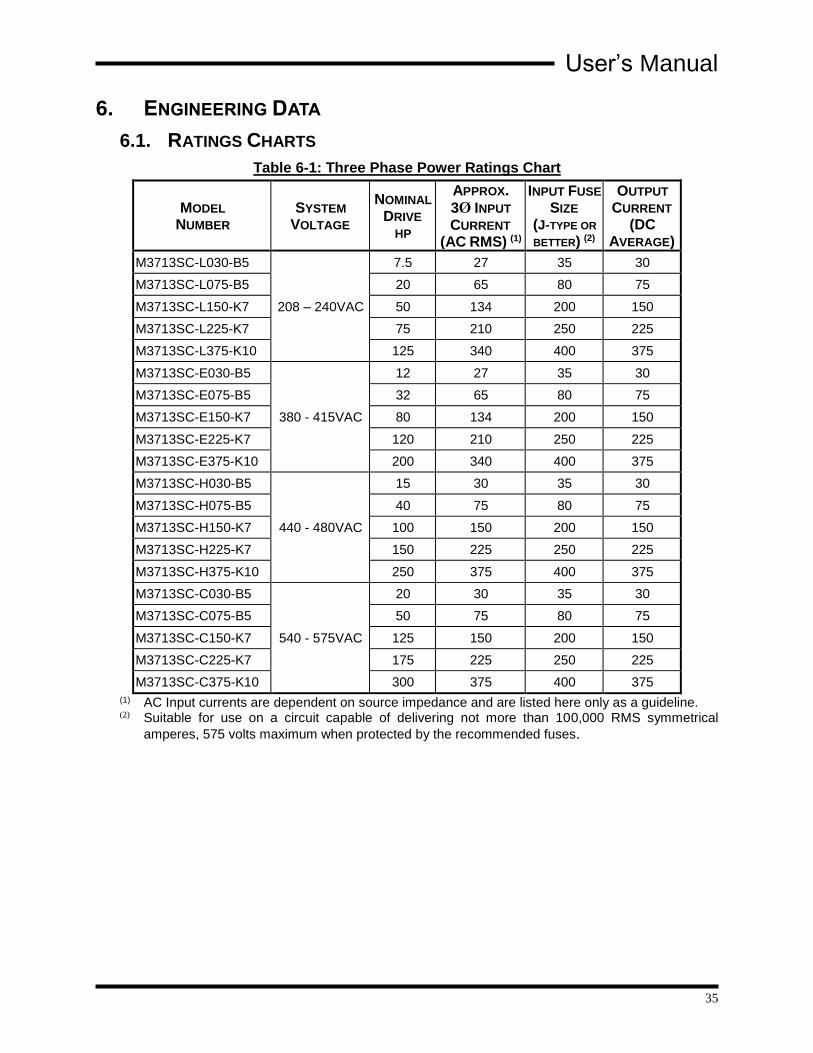
6. ENGINEERING DATA ................................................................................................................35 6.1. Ratings Charts ............................................................................................................................. 35
Table 6-1: Three Phase Power Ratings Chart ......................................................................................... 35 6.2. Watt Loss .................................................................................................................................... 36
Table 6-2: Full Load Watt Loss ............................................................................................................. 36 Table 6-3: Reactor Specifications Chart ................................................................................................ 36
6.3. Certifications .............................................................................................................................. 37 6.4. Dimensions and Outlines ............................................................................................................ 37
Table 6-4: Chassis Dimensions for M3713SC Module .......................................................................... 37 Figure 6-1: M3713SC B5 Chassis Dimensional Outline ........................................................................ 38 Figure 6-2: M3713SC K7 Chassis Dimensional Outline ....................................................................... 39 Figure 6-3: M3713SC K10 Chassis Dimensional Outline ..................................................................... 40
6.5. Block Diagram ............................................................................................................................ 41 Figure 6-4: M3713SC Functional Block Diagram ................................................................................. 41 Figure 6-5: 18 Pulse Functional Block Diagram .................................................................................... 42
7. APPLICATION NOTES ...............................................................................................................43 7.1. Application Considerations ........................................................................................................ 43
7.1.1. Drives .............................................................................................................................................. 43 7.1.2. M3713SC Parallel Power Supplies ................................................................................................. 44
7.2. System Voltage and Source Impedance ..................................................................................... 44 7.2.1. Transformers ................................................................................................................................... 44 7.2.2. Input Reactors ................................................................................................................................. 44
7.3. Input Voltage Imbalance............................................................................................................. 45 7.4. Sizing 12 or 18 Pulse Systems .................................................................................................... 45 7.5. M3713SC with Capacitor Bank .................................................................................................. 46
Figure 7-1: M3713SC with Capacitor Bank ........................................................................................... 46

M3713SC
6
This page intentionally left blank

User’s Manual
7
1. INTRODUCTION
1.1. WHO SHOULD USE This manual is intended for use by anyone who is responsible for integrating, installing, maintaining, troubleshooting, or using this equipment with any AC drive system.
Please keep this manual for future reference.
1.2. PURPOSE AND SCOPE This manual is a user’s guide for the Model M3713SC 3-phase power supply. It will provide you with the necessary information to successfully install and use the M3713SC modules in your application.
In the event of any conflict between this document and any publication and/or documentation related to the application, the latter shall have precedence.
1.3. MANUAL VERSION AND CHANGE RECORD Field wiring drawings were updated in Rev 00j.
Drives that cannot be powered updated in Rev 00k. Voltage ratings and reactors in parallel were updated in Rev 00m.
Voltage ranges were updated in Rev 00n.
Manual template was updated in Rev 01a.
Table 4-1, Section 3.4.1.1, and Section 4.2.5.6 were updated in Rev 01b.
Information regarding 12 and 18 pulse solutions was added in Rev 01c.
Section 7.4 M3713SC with capacitor banks was added in Rev 01d.
Updates were made to Table 6-3 and Figures 3-5 - 3-8, in Rev 01e.
Update made to Table 2-4 in Rev 01f.
Figure 1-1: Typical M3713SC 3-Phase Power Supply
M3713SC
8
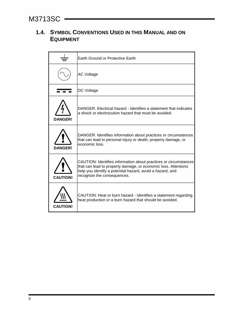
1.4. SYMBOL CONVENTIONS USED IN THIS MANUAL AND ON
EQUIPMENT
Earth Ground or Protective Earth
AC Voltage
DC Voltage
DANGER!
DANGER: Electrical hazard - Identifies a statement that indicates a shock or electrocution hazard that must be avoided.
DANGER!
DANGER: Identifies information about practices or circumstances that can lead to personal injury or death, property damage, or economic loss.
CAUTION!
CAUTION: Identifies information about practices or circumstances that can lead to property damage, or economic loss. Attentions help you identify a potential hazard, avoid a hazard, and recognize the consequences.
CAUTION!
CAUTION: Heat or burn hazard - Identifies a statement regarding heat production or a burn hazard that should be avoided.

User’s Manual
9
2. PRODUCT DESCRIPTION The M3713 is a non-regenerative 3-phase power supply intended for use as the main power supply for a common DC bus drive system. The drives can be either servo or variable frequency drives intended for use in common bus capacitors. The M3713SC has a selectable start-up current limit which is rated at approximately 20% of the full load rating for pre-charging the VFD bus.
2.1. RELATED PRODUCTS
COMMON BUS POWER SUPPLY WITHOUT PRECHARGE • M3713DM is a 3 phase power supply without precharge.
FUSE PLATE • M3713F fuse plate provides ready low cost fusing.
DC BUS CAPACITOR • M3612EC offers capacitors with integral bleeder resistors.
DC BUS SNUBBER • M3612RC adds extra snubbing to the DC bus for higher frequency bus filtering.
LINE REGEN • M3645 three phase line regen (30A – 300A)
• M3545 single or three phase line regen (<15A)
BRAKING TRANSISTORS • M3452 heavy duty braking transistor (<1600A)
• M3575T standard duty braking transistor (<600A)
• M3675T low HP braking transistor (<10A)
BRAKING RESISTORS • M3575R standard duty braking resistors (<30A)
• M3775R various duty load banks (<1600A)

M3713SC
10
2.2. PART NUMBER BREAKDOWN
Figure 2-1: Example of Part Number Breakdown
BASE MODEL NUMBER The base model number for the 3-phase power supply with precharge is M3713SC.
VOLTAGE RATING A 1-character code represents the 3-phase AC line input voltage to the M3713SC module. The voltage rating must be selected for the system voltage that will be applied.
Table 2-1: Voltage Rating
RATING CODE VOLTAGE
L 208 – 240 VAC ±10%
E 380 – 415 VAC ±10%
H 440 - 480VAC ±10%
C 540 – 575 VAC ±10%
CURRENT RATING A 3-digit code represents the maximum current that the M3713SC is intended to support. Exceeding this limit may cause poor performance and possible failure.
Table 2-2: Current Ratings
RATING CODE NOMINAL DRIVE CURRENT
030 30 A
075 75 A
150 150 A
225 225 A
375 375 A
BASE MODEL NUMBER
VOLTAGE RATING
CURRENT RATING
CURRENT RATING
NO RAMP LIMIT OPTION
K7 M3713SC L 150 NORL

User’s Manual
11
CHASSIS CODE An alphanumeric code represents the chassis style as defined below.
Table 2-3: Chassis Style
CHASSIS CODE
CURRENT DIMENSIONS (H X W X D)
B5 30-75A 17.75 x 5.50 x 7.80
K7 150-225A 20.00 x 7.12 x 10.35
K10 375A 20.00 x 10.00 x 10.50
NO RAMP LIMIT OPTION The No Ramp Limit Option is a version of the M3713SC will not have a limit on the precharge time. This option is indicated with the code NORL.
2.3. GENERAL SPECIFICATIONS
Table 2-4: General Specifications Chart
PARAMETER SPECIFICATION
Input Voltage 240VAC, 380VAC, 480VAC, 575VAC,
3Φ, 50 Hz, 60 Hz
Output Voltage DC Approximately 1.4x Input VAC
Intermittent Duty Limit 150% Full Load Rating for 60 seconds
Precharge Ramp Current Limit 20% Full Load Rating
Overcurrent Limit 175% Full Load Rating
Operating Temp 0C to +50C
Storage Temp -20C to +65 C
Humidity Below 90%
Non-condensing
Atmosphere Free of corrosive gas and conductive dust
Control I/O
Inputs: 24V+ Sinking
• PRECHARGE ENABLE
• RUN ENABLE
Outputs: 250VAC,120mA Max
• PRECHARGE COMPLETE
• READY
Indicators
POWER
READY
STATUS

M3713SC
12
2.4. GENERAL PRECAUTIONS AND SAFETY WARNINGS
DANGER!
• H IGH VOLT AGES MAY BE PRESENT !
• NEVER ATTEMPT TO OPER ATE OR SERVIC E THIS EQUIPMENT
WITH ACCESS DO ORS OR COVERS OPE NED !
• FAILURE TO HEED THESE WARNINGS MAY RESULT IN
SERIOUS BODILY INJURY OR DEATH!
CAUTION!
• H IGH TEMPERATURES MAY BE GENERATED BY THIS E QUI PMENT
DURING NORM AL OPE RAT IO N !
• THIS E QUIPMENT SHOULD BE INST AL LED ON A N ON -FLAMMABLE SURF AC E IN A WELL VENTILATED ARE A WITH A
M INIMUM OF 2 INCHES OF CLEAR ANCE ALL AR OUND .
• LETHAL V OLTAGES C AN EXIST IN UNIT AFT ER P OWER H AS BEEN
REMOVED . ALLOW 5 M INUTES FOR C AP ACITO R B ANKS T O
DISCH ARGE , AND EN SURE THERE ARE LESS THAN 40VDC ON
THE DC BUS BEFORE ATTEMPTI NG SERVICE .
• AL W AYS ALLOW AMP LE T I ME FOR THE UNIT TO C OOL BEF ORE
ATTEMPTING SERVICE O N THIS PRODUCT !
• INSTALLATIO N AND /O R REMOVAL OF THIS P RODUCT SHOULD
ONLY BE AC COMPLISHED BY A Q U ALIF IED ELEC TRICIAN IN
AC CORD ANCE WITH NATIO N AL ELECTRICAL CODE O R
EQUIV ALENT REGUL ATIO NS .
ANY QUESTIONS AS TO APPLICATION, INSTALLATION, OR SERVICE SAFETY SHOULD BE DIRECTED TO THE EQUIPMENT SUPPLIER.

User’s Manual
13
3. INSTALLATION INSTRUCTIONS
WARNING!
Installation and/or removal of this product should only be performed by a qualified electrician in accordance with National Electrical Code or local codes and regulations.
Proper installation of the power supply modules should be accomplished following the steps outlined below. Be sure to refer to the AC drive instruction manual as these steps are performed. Please direct all installation inquiries that may arise during the installation and startup of this product to the equipment supplier or system integrator.
3.1. ENVIRONMENT The module should be installed in an area protected from moisture and falling debris.
Buildup of dust or debris may cause poor performance and possibly failure. Operating in a wet environment can pose a shock hazard. The recommended temperature range
for operating or storing this module is 0C to +50C.
3.2. UNPACKING Upon receipt of this product, please verify that the product received matches the product that was ordered and that there is no obvious physical damage to the unit. If the wrong product was received or the product is damaged in any way, please contact the supplier from which the product was purchased.
3.3. MOUNTING
3.3.1. MOUNTING THE M3713SC 3-PHASE POWER SUPPLY
The installation site for the module should be chosen with several considerations in mind:
• The unit requires a minimum clearance of two (2) inches in all directions when mounted near a non-heat source.
• Unit should not be exposed to falling debris or condensation. • The M3713SC must be properly oriented for proper heat flow through
the units. The M3713SC must be mounted with the rear surface of the unit to the mounting surface. Unit should be mounted vertically as shown in Example A of Figure 3-1. • Do Not mount the unit upside-down or on the underside of a
mounting surface as shown in Example B of Figure 3-1. • Do Not mount unit in a horizontal position with its side parallel to the
mounting surface or floor as shown in Example C of Figure 3-1.
Figure 3-1: M3713SC Mounting Orientation
HORIZONTAL TO FLOOR
Example A
HORIZONTAL SURFACEVERTICAL SURFACE
UP
UP
Example B Example C
HANGING UNDERSIDE
UP

M3713SC
14
3.4. WIRING AND CUSTOMER CONNECTIONS Be sure to review all AC drive and system documentation for attached equipment as well as the information listed below before proceeding. Connection points and terminal numbers of the AC drive will be found in the documentation provided with those units. See Table 3-1 and Figure 3-2 for connection details.
Use copper conductors rated 75°C.
3.4.1. POWER WIRING
WARNING!
Only qualified electricians should perform and maintain the interconnection wiring of this product. All wiring should be done in accordance with local codes.
WARNING!
This unit contains substantial capacitance and can maintain lethal voltages for a long time after power is removed! Ensure that the DC bus level has dropped below 40VDC before attempting to work on or with this unit!
Table 3-1: Power Connection Specifications
MODEL CONNECTOR WIRE SIZE
RANGE(1)(2) TORQUE
L030
E030
H030
C030
6 - 20 AWG 13-16 lb-in
L075
E075
H075
C075
2 - 14 AWG 35-50 lb-in
L150
E150
H150
C150
2/0 - 14CU / 8AL 120 lb-in
L225
E225
H225
C225
350 kcmil - 6 AWG 275 lb-in
L375
E375
H375
C375
500 kcmil - 6 AWG 500 lb-in
(1) Maximum and minimum are the sizes that the terminal block will accept. These are not sizing recommendations. (2) Use copper conductors rated for 75°C.
User’s Manual
15
3.4.1.1. MAIN AC INPUT
ATTENTION!
When operating this unit with generator, verify the generator is properly sized for required load. The generator may slow down when the drive is precharged and running at full load.
The AC input should be connected to a 3-phase source following the typical guidelines used when sizing for an inverter. Refer to the chart in Section 6.1 for guidance in conducting and overcurrent protection sizing.
The input is not sensitive to phase rotation. The unit will operate properly if the phasing is ABC or ACB.
Many installations will need to use an input reactor to reduce the AC input currents as well as the DC bus ripple. Bonitron recommends at least 3% source impedance. If your source transformer is very large compared to the input rating of the power supply, you may need to provide an input reactor.
Reactors “MUST” be installed when using parallel power supplies. Do not parallel power supplies with different current ratings.
Refer to the Application Notes in Section 7 for more information on input impedance.
3.4.1.2. OUTPUT TO VFD DC─ and DC+ should be connected to the DC bus terminals of the VFD respectively. Ensure the polarity of the connection is correct, as this can cause severe damage to the drive. Refer to your drive manual for the exact location of this connection.
This link should be fused in accordance with the drive manufacturer’s recommendations. If the M3713SC is installed in the same cabinet as the VFD, DC link fusing may not be necessary. Semiconductor fuses such as the A70Q or FWP are recommended for this purpose.
ATTENTION!
This power supply does not contain filter capacitance!
Filter capacitors must be integrated into the drive or installed separately.
See Application Notes in Section 7 for assistance.
It is usually not necessary to attach AC power to the attached drive. Refer to your drive manual for more information.
Do not connect the output of the M3713SC to the braking terminals of the drive. This can also cause severe damage to the drive.
3.4.1.3. GROUNDING CONSIDERATIONS Using the ground stud provided, ground the chassis in accordance with local codes. Typically, the wire gauge will be the same as is used to ground the attached drive.
Refer to your local codes and standards for installation guidelines.
M3713SC
16
3.4.2. I/O WIRING
Table 3-2: I/O Wiring Specifications
TERMINAL FUNCTION ELECTRICAL
SPECIFICATIONS MIN WIRE
AWG MAX WIRE
AWG TORQUE
LB-IN
TB2-1 NC
TB2-2&3 PRECHARGE COMPLETE
250VAC / 120mA max 26 16 4.5 lb-in
TB2-4&5 READY 250VAC / 120mA max 26 16 4.5 lb-in
TB2-6 24V (24V, 100mA) 26 16 4.5 lb-in
TB2-7 PRECHARGE
ENABLE (24V, 100mA) 26 16 4.5 lb-in
TB2-8 24V (24V, 100mA) 26 16 4.5 lb-in
TB2-9 RUN ENABLE (24V, 100mA) 26 16 4.5 lb-in
TB2-10 COM (24V, 100mA) 26 16 4.5 lb-in

User’s Manual
17
3.5. TYPICAL CONFIGURATIONS
Figure 3-2: M3713SC 3-Phase Power Supply Field Wiring Diagram (Single VFD)

M3713SC
18
Figure 3-3: M3713SC 3-Phase Power Supply Field Wiring Diagram (Multiple VFD)

User’s Manual
19
Figure 3-4: M3713SC 3-Phase Power Supply Field with M3645 Regen Wiring Diagram

M3713SC
20
3.6. TYPICAL 12 PULSE CONFIGURATIONS
Figure 3-5: M3713SC 12-Pulse System
Figure 3-6: M3713SC 12-Pulse System with VFD

User’s Manual
21
3.7. TYPICAL 18 PULSE CONFIGURATIONS
Figure 3-7: M3713SC 18-Pulse System

M3713SC
22
Figure 3-8: M3713SC 18-Pulse System with VFD

User’s Manual
23
4. OPERATION
4.1. FUNCTIONAL DESCRIPTION The M3713SC 3-phase power supply uses an SCR bridge with phase control to provide DC voltage. These supplies may be used as common bus supplies for multiple drives and inverters.
They can also be used in parallel configurations, such as in 12 or 18 pulse bridge systems. See Section 4.3.2 for further information on interconnecting parallel units.
A complete system will require the M3713SC power supply, bulk bus filtering capacitors, inverters or drives, and any common braking or filtering systems required for the application.
4.1.1. PRECHARGE
The M3713SC DC bus supply has a precharge function that slowly ramps the capacitor bank to full voltage before going into full operation to minimize the inrush currents during bus charging. This function is an automatic current controlled ramp that allows the unit to go into full conduction as soon as the full voltage is sensed on the output. If the unit cannot charge the output, the unit will not go into operation and a fault will be shown.
4.1.2. OPERATION
During operation, the unit will sense the output for several parameters, including undervoltage, overcurrent, overtemperature and other operational faults. If a fault is sensed, the unit will shut down the DC output, and the fault code will be displayed on the front panel of the unit.
4.2. FEATURES
4.2.1. I/O – INPUTS AND OUTPUTS
4.2.1.1. TB2-2&3 PRECHARGE COMPLETE CONTACTS The PRECHARGE Complete contacts will close when the unit has completed precharging.
This output can be used in configurations to stage multiple power supplies are used in parallel.
Please refer to the Application Notes for further information on interconnecting parallel units.
4.2.1.2. TB2-4&5 READY CONTACTS The READY contacts will close when the unit is ready to operate at full capacity. This contact will close after the precharge is complete, and the RUN ENABLE input is on.
The READY output will open on any fault.
The attached drive system should not be started until the READY contacts close.
M3713SC
24
4.2.1.3. TB2-7 PRECHARGE ENABLE INPUT A +24VDC signal will enable the unit for precharge. These inputs are isolated so they may be interfaced with PLC or external switch.
Once the contact is closed, the unit will ramp the voltage to the maximum output in approximately 2½ seconds in order to precharge the bus capacitance. If the current during this ramp exceeds the current limit, the ramp will take longer. See Section 5.3.3.1 for details on setting this limit. If the precharge sequence takes longer than 5 seconds, the unit will stop precharging and go into a fault mode unless that unit has the No Ramp Limit Option.
If the Enable input is left open, the unit will remain in standby.
Once this input goes off, all faults but phase loss are cleared, and the unit can be enabled again to continue operation.
4.2.1.4. TB2-9 RUN INPUT The second enable is used when there is more than one unit connected to each other. Once the PRECHARGE Complete output comes on, the RUN Input will need a +24VDC input within 6 seconds to continue operation. If the RUN Input does not go high, the unit will go into a fault mode and the DC output will go to zero.
If the unit is not used in a multiple configuration, this input can be effectively disabled by placing JP1 on the circuit board, or by placing a jumper between TB2-8 and TB2-9.
4.2.1.5. TB2-10 COMMON This is the common for the inputs, and can be used if the inputs are to be driven by an external power source. This common must be connected to the common of the external power source for the inputs to operate.
4.2.2. JUMPERS
4.2.2.1. JP1 – STAND ALONE OPERATION JP1 is used to disable the function of the RUN Input, described in Section 4.2.1.4. When this jumper is installed, the RUN Input is held high, and when the unit finishes precharge, will go immediately into full conduction operation.
This jumper can also be installed if parallel units are not used in a cascade configuration.

User’s Manual
25
Figure 4-1: K7 and K10 Chassis Jumper 1 Location
Figure 4-2: B5 Chassis Jumper 1 Location
4.2.3. TIMING CHART
The timing charts in Figure 4-3 show the typical modes of operation.
Figure 4-3: Typical Modes of Operation
Enable 1
Input
Enable 2
Input
Precharge
Complete
Ready
Output
DC Bus
Time
Cascade Operation
Enable 1
Input
Enable 2
Input
Precharge
Complete
Ready
Output
DC Bus
Time
Single Operation

M3713SC
26
4.2.4. EXTERNAL INDICATORS
The unit has indicators in the front panel that will show basic status information for the supply and can be used for troubleshooting or general information.
4.2.4.1. POWER The POWER indicator on the front of the unit will be illuminated when control power is applied to the bridge and the processor is functioning properly.
4.2.4.2. READY The Ready indicator illuminates when the unit has power applied and is ready to operate.
When the Enable input is activated, the indicator will be flashing during the precharge portion of operation.
When the unit is done pre-charging, this indicator will be solid, and the Ready contact will close.
4.2.4.3. STATUS INDICATOR The Status indicator illuminates when there is a fault active in the unit. When this indicator is on, the Ready contact will open, and the unit will not supply power to the VFD.
If there are no faults, this indicator will be off.
The blink sequence will indicate the specific fault. See Table 4-1 for more information on the sequence of flashes.
4.2.5. FAULT MODES
When the unit is in a fault, there is no output from the converter, and the power supply shuts down. All faults are cleared by powering the unit down and restarting, or by toggling the PRECHARGE ENABLE input. When the PRECHARGE ENABLE input is low, the blink code will continue to show the condition of the last fault. See Troubleshooting in Section 5 for further assistance on any of the following alarms.
Table 4-1: Blink Patterns
BLINK PATTERN FAULT CONDITION
Fast Blink Precharging
Off No Fault
On Missing Run Input
On – Off Ramp Limit
On – On – Off Overcurrent
On – On – On – Off Overtemperature
On – On – On – On – Off Undervoltage
On – On – On – On – On- Off Phase Loss
On – On – On – On – On – On - Off Frequency Loss

User’s Manual
27
4.2.5.1. PRECHARGING When the unit is precharging the output, the Status Input will flash rapidly. This does not indicate a fault, but does indicate that the unit has a PRECHARGE ENABLE input and the ramp has not completed.
Once the unit goes through precharge successfully, the unit will go into full conduction, and the Status light should go off.
If the unit does not go through precharge successfully, the unit will indicate one of the faults listed below.
4.2.5.2. MISSING RUN INPUT When precharging is complete, unit must see the Run Input within six seconds. If the Run Input does not go high, the unit will shut down.
4.2.5.3. RAMP LIMIT If the unit tries to precharge for more than 5 seconds without reaching the full output voltage, the unit will go into a Ramp Limit fault. This indicates that the unit was unable to precharge the load.
This fault is reset on power down, or when the ENABLE input is removed.
If the unit has the NORL option then the unit does not have a ramp limit and this fault will not occur.
4.2.5.4. OVERCURRENT If there is a sustained current demand over 175% of the units rated current output, the unit will shut down.
Do not use this fault as a substitute for circuit overcurrent protection. Fuses or circuit breakers should be installed in accordance with local codes and regulations.
This fault is reset on power down, or when the ENABLE input is removed.
4.2.5.5. OVERTEMPERATURE This indicates that the unit’s heatsink has exceeded 160°F. The unit will shut down and the fault will not reset until the heatsink cools.
Once the unit cools, the fault can be reset on power down, or when the ENABLE input is removed.
4.2.5.6. UNDERVOLTAGE After the unit is precharged, the output voltage is monitored. If the output voltage drops below 50% of the nominal output voltage, the unit will generate an undervoltage fault. This can indicate a problem with either the input voltage or a hookup problem. See Troubleshooting in Section 5.3 for further assistance.
This fault is reset on power down, or when the ENABLE input is removed.
4.2.5.7. PHASE LOSS The unit must have input power to all phases to operate correctly. The unit does not need a specific phase rotation, but the loss of a phase will cause the unit to shut down. This fault is reset on power down, or when the ENABLE input is removed.
4.2.5.8. FREQUENCY LOSS This indicates the unit failed to properly detect the frequency of the AC source. This fault latches until the unit is powered down.

M3713SC
28
4.3. STARTUP This section covers basic checks and procedures that may be used when performing a startup with a M3713SC.
4.3.1. PRE-POWER CHECKS
• Ensure that all connections are tight and that all wiring is of the proper size and rating for operation.
• Verify continuity of all input fuses. • Ensure that the polarity of the DC link to the attached drive is correct. • Check for exposed conductors that may lead to inadvertent contact. • Check for any debris, shavings, trimmings, etc. that may cause shorts
or obstruct ventilation on unit. • Perform the pre-power checks required for the attached drive.
4.3.2. STARTUP PROCEDURE AND CHECKS
4.3.2.1. SINGLE MODULE OPERATION • For single mode operation, JP1 should be installed, or the Run
Enable input should be jumpered high. See Section 4.2.2.1 for more information.
• After completing pre-checks and the recommended checks for the connected equipment, apply power to the system.
• The POWER indicator on the front panel will illuminate. • Close the contact on the PRECHARGE ENABLE input. • The STATUS indicator will flash rapidly during precharge. • Once PRECHARGE is complete, the Ready indicator will stay on
solid, and the Ready contacts will close. • The attached drive should then be started up according to its
instructions.
4.3.2.2. PARALLEL MODE OPERATION Parallel mode can be used when the system can have all of the units pre-charging at once. In this case, the PRECHARGE ENABLE is wired to all of the units in parallel, and all units will start at once. In this mode, all units can be jumpered to ignore the Run Enable input.
An example of this wiring is shown in Figure 4-4.
A fault on one unit will not affect the operation of the others, and the individual Ready contacts can be monitored remotely to de-rate or stop the system output as required.
• After completing pre-checks and recommended checks for connected equipment, apply power to the system.
• The POWER indicator on the front panels will illuminate. • Close the contact on the PRECHARGE ENABLE inputs. • The STATUS indicator will flash rapidly during precharge. • Once PRECHARGE is complete, the Ready indicators will stay on
solid, and the Ready contacts will close. • The attached drive should then be started up according to its
instructions.
User’s Manual
29
Figure 4-4: Parallel Mode Interconnection
4.3.2.3. CASCADE MODE OPERATION Cascade mode can be used to allow an interconnection of multiple power supplies to disable all other power supplies in the event of an individual fault.
The system ENABLE is wired to the first power supply in the system and the rest are daisy chained using the PRECHARGE Complete output.
An example of this wiring is shown in Figure 4-5.
• After completing pre-checks and the recommended checks for the connected equipment, you may apply power to the system.
• The POWER indicator on the front panels should illuminate. • Close the contact on the PRECHARGE ENABLE input to the first
unit. • The STATUS indicator will flash rapidly during precharge. • Once PRECHARGE is complete, the first unit will enable the
precharge for the next unit in the chain. The next unit’s STATUS indicator should flash briefly and likewise with the other units in the chain.
• Once all units have gone through the precharge cycle, the last unit will enable the RUN ENABLE input on the first unit in the chain, and the signal will cascade down through the other units.
• READY indicators should stay on solid, and the READY contacts will close.
• The attached drive should then be started up according to its instructions.
• In the event of a single power supply fault, all the units will be disabled, and fault codes will be displayed on the faulted units. The unit that initiated the fault will have a fault code different from Missing Run Input.

M3713SC
30
Figure 4-5: Cascade Mode Interconnection
User’s Manual
31
5. MAINTENANCE AND TROUBLESHOOTING Repairs or modifications to this equipment are to be performed by Bonitron approved personnel only. Any repair or modification to this equipment by personnel not approved by Bonitron will void any warranty remaining on this unit.
5.1. PERIODIC TESTING There are no requirements for periodic testing of these units. When performing routine maintenance it may be beneficial to repeat start-up procedures and checks.
5.2. MAINTENANCE ITEMS Check periodically for debris, clear as necessary. Buildup can cause short circuits and dangerous conditions.
Reduced airflow can cause nuisance tripping and overheating.
Power should not be applied when blowing dust and debris out of unit.
5.3. TROUBLESHOOTING
WARNING!
This unit contains substantial capacitance and can maintain lethal voltages for a long time after power is removed! Ensure that the DC bus level has dropped below 40VDC before attempting to work on or with this unit!
ATTENTION!
Only qualified personnel familiar with adjustable frequency AC drives and associated machinery should plan or implement the installation, start-up and subsequent maintenance of the system. Failure to comply may result in personal injury, death and/or equipment damage!
Feel free to call Bonitron at any time the equipment appears to be having problems.
5.3.1. POWER INDICATOR IS NOT ON
• Check AC input voltage at TB1 terminals 1, 2 and 3. This voltage should be the same as the system voltage for the unit, either 240VAC for L units, 480VAC for H units or 575VAC for C units.
• If there is voltage at these terminals, and the POWER indicator is not on, the unit may be damaged, and need repair. Contact your supplier or Bonitron for assistance.
5.3.2. ATTACHED DRIVE DOES NOT COME ON
• If the POWER Indicator is on, make sure the ENABLE inputs are activated by closing a contact between TB2 6 and 7 to enable the precharge and between TB2 8 and 9 to enable the unit with either a switch or jumper.
• The STATUS indicator should begin to flash rapidly, or come on solid. • If the STATUS indicator does not flash or come on solid, then check the
connection to the Enable Input. • If the READY indicator comes on solid, check the connections between
the M3713SC and the attached drive. If there are fuses in the link, make sure they are not blown.
• If the READY indicator does not come on solid, continue troubleshooting below.

M3713SC
32
5.3.3. STATUS INDICATOR FLASHES
Check the blink codes listed in Table 4-1 for the specific fault indicated. Once a fault is sensed, the STATUS indicator will continue to flash the fault code until the unit is powered down, or the PRECHARGE ENABLE input is toggled off and then back on.
5.3.3.1. RAMP LIMIT Ramp Limit occurs when the unit is unable to precharge the output within 5 seconds. The input ramp current limit is factory set to 20% of the output rating of the unit. This is usually sufficient to precharge any attached load. If it is not, this can indicate one of the following:
1. The attached drive exceeds the ratings of the M3713SC. 2. The attached drive is already enabled and loaded. 3. The drive may have a large capacitor bank. 4. The wiring may be faulty between the drive and the M3713SC.
Follow these steps to try to determine the problem:
• Power down the unit and check the wiring thoroughly to make sure there are no faulty connections or shorts between the drive and the M3713SC.
• Ensure that the drive is not enabled or started during precharge. One way to ensure this is to use the READY contact in the start/stop string of the drive’s control input.
• Check the DC bus voltage during precharge. If the voltage rises during the precharge sequence, make sure the M3713SC unit is rated for the drive attached.
5.3.3.2. OVERCURRENT If there is a sustained current demand over 175% of the unit’s rated current output, the unit will shut down.
Do not use this fault as a substitute for circuit overcurrent protection. Fuses or circuit breakers should be installed in accordance with local codes and regulations.
This fault is reset on power down, or when the ENABLE input is toggled off and back on.
• Power down the unit and check the wiring thoroughly to make sure there are no faulty connections or shorts between the drive and the M3713SC.
• Enable the unit and measure the current during operation and ensure it does not exceed the rating of the power supply.
• If the fault reappears, make sure the M3713SC unit is rated for the drive attached. If so, there may be an issue with the attached drive.
5.3.3.3. OVERTEMPERATURE This indicates that the unit’s heatsink has exceeded 70°C (160°F). The unit will shut down until the heatsink cools.
Once the unit cools, the fault can be reset on power down, or when the ENABLE input is removed.
If the unit frequently overheats, it may be overloaded. The M3713SC is designed for 150% of rated output current for 60 seconds at a maximum of 40°C (104°F). If the ambient temperature around the M3713SC is higher than this, the unit must be de-rated.

User’s Manual
33
Ensure that the fan is running when the unit is hot. The fan will start running when the heatsink reaches 45°C (110°F).
5.3.3.4. UNDERVOLTAGE This indicates the output DC voltage has dropped to a level insufficient to continue operation. If this occurs, monitor the DC bus voltage and the AC input voltage.
Verify that the source voltage is not being reduced too much when the system is loaded, as the input impedance to the power supply may be too high.
See Section 7 for additional information.
5.3.3.5. PHASE LOSS The unit has phase loss detection that will shut the unit down in case one or more of the input phases is lost because of a fuse or other fault. This is to protect the unit from an unbalanced input.
If you are showing a phase loss, check the main input devices to each incoming leg, such as fuses or circuit breakers.
5.3.3.6. FREQUENCY LOSS The unit cannot find the frequency of AC source. This fault should only occur directly after the unit is first powered on. This is a latching fault and power to the M3713SC should be cycled to clear the fault. If the fault fails to clear check all incoming AC fuses.
5.4. TECHNICAL HELP – BEFORE YOU CALL If technical help is required, please have the following information when calling:
• Serial number of unit
• Name of original equipment supplier (if available)
• Record the line voltage
• Record the DC bus voltage immediately after the AC voltage
• Brief description of the application
• Drive and motor hp or kW
• kVA rating of power source
• Source configuration and grounding

M3713SC
34
This page intentionally left blank
User’s Manual
35
6. ENGINEERING DATA
6.1. RATINGS CHARTS
Table 6-1: Three Phase Power Ratings Chart
MODEL NUMBER
SYSTEM
VOLTAGE
NOMINAL
DRIVE HP
APPROX.
3Ø INPUT
CURRENT (AC RMS) (1)
INPUT FUSE
SIZE
(J-TYPE OR
BETTER) (2)
OUTPUT
CURRENT (DC
AVERAGE)
M3713SC-L030-B5
208 – 240VAC
7.5 27 35 30
M3713SC-L075-B5 20 65 80 75
M3713SC-L150-K7 50 134 200 150
M3713SC-L225-K7 75 210 250 225
M3713SC-L375-K10 125 340 400 375
M3713SC-E030-B5
380 - 415VAC
12 27 35 30
M3713SC-E075-B5 32 65 80 75
M3713SC-E150-K7 80 134 200 150
M3713SC-E225-K7 120 210 250 225
M3713SC-E375-K10 200 340 400 375
M3713SC-H030-B5
440 - 480VAC
15 30 35 30
M3713SC-H075-B5 40 75 80 75
M3713SC-H150-K7 100 150 200 150
M3713SC-H225-K7 150 225 250 225
M3713SC-H375-K10 250 375 400 375
M3713SC-C030-B5
540 - 575VAC
20 30 35 30
M3713SC-C075-B5 50 75 80 75
M3713SC-C150-K7 125 150 200 150
M3713SC-C225-K7 175 225 250 225
M3713SC-C375-K10 300 375 400 375
(1) AC Input currents are dependent on source impedance and are listed here only as a guideline. (2) Suitable for use on a circuit capable of delivering not more than 100,000 RMS symmetrical
amperes, 575 volts maximum when protected by the recommended fuses.

M3713SC
36
6.2. WATT LOSS Table 6-2 lists the maximum watt loss generated by the listed units. When installing M3713SC units in an enclosure, consideration should be given to internal temperature rise. The following table is based upon the maximum capability of each unit.
Table 6-2: Full Load Watt Loss
OUTPUT
CURRENT FULL LOAD OF
POWER SUPPLY
30 A 150 W
75 A 260 W
150 A 500 W
225 A 800 W
375 A 1150 W
Applications that do not utilize the full capacity may be calculated as follows:
𝑊𝑎𝑡𝑡 𝐿𝑜𝑠𝑠 = 𝐹𝑢𝑙𝑙 𝐿𝑜𝑎𝑑 𝑊𝑎𝑡𝑡 𝐿𝑜𝑠𝑠 (𝐴𝑣𝑒𝑟𝑎𝑔𝑒 𝐻𝑃
𝑅𝑎𝑡𝑒𝑑 𝐻𝑃)
Table 6-3: Reactor Specifications Chart
M3713SC MODEL
NUMBER
SYSTEM
VOLTAGE
NOMINAL
DRIVE HP
BONITRON
REACTOR
NUMBER
REACTOR
INDUCTANCE µH
M3713SC-L030-B5
208 – 240VAC
7.5 IN RL-03502 800
M3713SC-L075-B5 20 IN RL-08002 400
M3713SC-L150-K7 50 IN RL-13001 100
M3713SC-L225-K7 75 IN RL-20002B14 110
M3713SC-L375-K10 125 IN RL-32002B14 75
M3713SC-E030-B5
380 - 415VAC
12 IN RL-02503 1800
M3713SC-E075-B5 32 IN RL-05503 850
M3713SC-E150-K7 80 IN RL-16003 230
M3713SC-E225-K7 120 IN RL-20003B14 185
M3713SC-E375-K10 200 IN RL-32003B14 125
M3713SC-H030-B5
440 - 480VAC
15 IN RL-02503 1800
M3713SC-H075-B5 40 IN RL-05503 850
M3713SC-H150-K7 100 IN RL-13003 300
M3713SC-H225-K7 150 IN RL-20003B14 185
M3713SC-H375-K10 250 IN RL-32003B14 125
M3713SC-C030-B5
540 - 575VAC
20 IN RL-02503 1800
M3713SC-C075-B5 50 IN RL-05503 850
M3713SC-C150-K7 125 IN RL-13003 300
M3713SC-C225-K7 175 IN RL-20003B14 185
M3713SC-C375-K10 300 IN RL-32003B14 125

User’s Manual
37
6.3. CERTIFICATIONS All M3713 models are UL and cUL listed by Underwriter's Laboratories under file number E204386 for UL508C Power Conversion Equipment
6.4. DIMENSIONS AND OUTLINES
Table 6-4: Chassis Dimensions for M3713SC Module
MODEL NUMBER CHX
OVERALL
(IN INCHES)
MOUNTING
(IN INCHES) WEIGHT
(LBS.) HEIGHT WIDTH DEPTH HEIGHT WIDTH
M3713SC-L030
B5 17.75 5.50 7.80 16.75 3.0 16.5 M3713SC-E030
M3713SC-H030
M3713SC-C030
M3713SC-L075
B5 17.75 5.50 7.80 16.75 3.0 16.5 M3713SC-E075
M3713SC-H075
M3713SC-C075
M3713SC-L150
K7 20.00 7.12 10.30 19.25 5.0 26.5 M3713SC-E150
M3713SC-H150
M3713SC-C150
M3713SC-L225
K7 20.00 7.12 10.30 19.25 5.0 28.5 M3713SC-E225
M3713SC-H225
M3713SC-C225
M3713SC-L375
K10 20.00 10.00 10.50 19.00 7.0 41.5 M3713SC-E375
M3713SC-H375
M3713SC-C375

M3713SC
38
Figure 6-1: M3713SC B5 Chassis Dimensional Outline

User’s Manual
39
Figure 6-2: M3713SC K7 Chassis Dimensional Outline

M3713SC
40
Figure 6-3: M3713SC K10 Chassis Dimensional Outline

User’s Manual
41
6.5. BLOCK DIAGRAM
Figure 6-4: M3713SC Functional Block Diagram
DC LINK3 PHASE 3713
COMMON BUSPOWER SUPPLY
VFDDC INPUT DC INPUT
VFDDC INPUT
VFD
CONTINUOUS COMMON DC BUS POWER SUPPLY
3713COMMON BUS
POWER SUPPLY
3713COMMON BUS
POWER SUPPLY
3 PHASE
3 PHASE
*
*
*
*OPTIONAL FOR SINGLE UNITS
MANDATORY FOR PARALLEL UNITS

M3713SC
42
Figure 6-5: 18 Pulse Functional Block Diagram
IN
VE
RT
ER
MO
TO
R
ST
AN
DA
RD
A
C D
RIV
E
User’s Manual
43
7. APPLICATION NOTES
7.1. APPLICATION CONSIDERATIONS The M3713SC is a 3-phase DC power supply. There are some issues that should be considered when designing the complete system.
7.1.1. DRIVES
Most variable frequency and servo drives are suitable for use with the M3713SC. Some things to consider are listed below. Check the manual of the drive you are using, or call the technical support line for the drive manufacturer if you have questions on this hookup.
7.1.1.1. DC CONNECTION The majority of variable frequency AC drives have a direct connection to the capacitor bank of the drive. This allows the M3713SC to precharge and run the drive directly through this connection, and should cause no problems with drive operation.
In general, the hookup can be described as a common bus input.
Check the manual of the drive you are using, or call the technical support line for the drive manufacturer if you have questions on this hookup.
7.1.1.2. DRIVES UNABLE TO BE POWERED FROM DC BUS Due to connection points and certain topologies some drives may not be compatible with external DC supplies. The following drives do not support external DC supplies. Please consult drive manufacturer for details and support.
• Allen Bradley Powerflex 4 series
• Allen Bradley Powerflex 400-E frame.
7.1.1.3. ADDITIONAL CAPACITANCE There must be a suitable amount of bus filter capacitance for each drive in the system. Many drives have these filter capacitors installed internally.
If your drives do not have internal capacitance, additional capacitance may be included. Refer to your drive documentation for further information.
A rule of thumb is that there should be at least 40µF of capacitance per amp of supply, in other words, a 100 amp supply would need 4000µF of total capacitance to have acceptable ripple.
7.1.1.4. AC INPUT LOSS DETECTION Some variable frequency AC drives incorporate AC input line sensing that causes a fault in the drive when the AC input lines are not used.
If the drive has phase loss detection, you can usually bypass this fault to allow the system to run without the AC input being connected.
7.1.1.5. 3-PHASE LOADS A few large frame AC drives have 3-phase blower motors integral to the drive. If this is the case, the blower will not operate when the drive is powered from the M3713SC. This can cause overheating and drive faults or failure.

M3713SC
44
Some packaged drives may also have other 3-phase loads in the cabinets such as fans or power supplies.
If you have a drive that has an integral 3-phase motor, consult your drive manufacturer for a possible solution. One may be to install a small inverter or drive to power the 3-phase loads from the output of the M3713SC.
7.1.2. M3713SC PARALLEL POWER SUPPLIES
When placing the M3713SC in parallel with other power supplies, only use power supplies with the same model number. Line reactors are required for each M3713SC when the units are placed in parallel, except for twelve and eighteen pulse systems that have a phase shifted transformer providing each rectifier with a separate AC input.
7.2. SYSTEM VOLTAGE AND SOURCE IMPEDANCE The M3713SC is intended to be used with an input reactor for the reduction of peak input currents and bus ripple. The reactor adds inductive impedance to the circuit to reduce these factors, and adds to the total input impedance of the system. Other sources of inductive impedance in your installation are the main incoming transformer and the conductors to that transformer. If the total input impedance is too high, it can cause low voltage at the input of the M3713SC, and therefore the DC bus of the drive. This is referred to as a “soft” source, and will have a transformer closely matched to the load and high impedance.
7.2.1. TRANSFORMERS
Transformers are rated in kVA and percent impedance. In order to see what kVA your system needs, you can roughly multiply the horsepower by 1000. Your transformer should be rated higher than this. In other words, a 50 horsepower system would require at least a 50kVA transformer, if not larger. If the transformer has 5% impedance, the voltage drop to the output of the transformer at full load will be 5%. For instance, a transformer with 5% impedance and an open terminal voltage of 480VAC can have only 456VAC at the terminals at full load. If the transformer is much larger than the required kVA, or has a low percent impedance, the source is considered to be “stiff” and can cause high charging currents, high input harmonics, and system overheating. If the input impedance is too high to the system, the input to the M3713SC can drop to the point where the DC bus of the drive will be out of specifications. When the DC bus falls too low, the motor can lose power or run hotter than usual. If the DC bus falls low enough, the drive will trip and not operate the motor. This typically is shown as an undervoltage fault on the drive.
7.2.2. INPUT REACTORS
Input reactors are used for many reasons, all of which are related. Input reactors reduce the peak input currents to the power supply and provide some protection from incoming spikes and surges. When using parallel power supplies, input reactors must be used to ensure current sharing between the inputs. This does not apply to twelve or eighteen pulse installations because the rectifiers are not in parallel as each rectifier has a separate phase-shifted AC feed.
User’s Manual
45
A minimum of 3% impedance should be used along with a derating of 10% for the combined power supply capacity. The impedance of the reactor reduces the RMS input currents, which can reduce nuisance tripping of incoming overload protection devices. The bus voltage ripple is also reduced, which causes less capacitor heating and therefore increases capacitor lifespan. Input reactors are generally rated for RMS current and percentage, much as transformers are rated. If the reactor has 5% impedance, the voltage drop to the output of the reactor at full load will be 5%. For instance, a 480V reactor with 5% impedance can only have 456VAC at the terminals at full load. If the total input impedance is too high to the system, the input to the M3713SC can drop to the point where the DC bus of the drive will be out of specifications. When the DC bus falls too low, the motor can lose power or run hotter than usual. If the DC bus falls low enough, the drive will trip and not operate the motor. This typically is shown as an undervoltage fault on the drive.
7.3. INPUT VOLTAGE IMBALANCE The balance between phases on the input of a 3-phase system can be critical. Depending on input impedances, a voltage imbalance of as little as 3% can cause the 3-phase bridge to effectively operate as a single phase bridge. This causes high input currents and capacitor overheating.
Isolation transformers can be used to mitigate voltage imbalances seen from the incoming supplies.
7.4. SIZING 12 OR 18 PULSE SYSTEMS When choosing which M3713SC power supplies to use in 12 or 18 pulse systems, the design is governed by the size of the motor and the VFD. The VFD’s inverter section must be sized to handle the load power. However, because the total load current is being supplied through several rectifying front ends the M3713SC does not have to be sized to handle the full load current.
If the rectifier section of the VFD is being utilized, then only a single M3713SC power supply is required for 12 pulse systems (See Figure 3-5). While two M3713SC power supplies are required for 18 pulse systems (See Figure 3-6).
If the VFD does not have a rectifier front end or is not being utilized in order to create a common DC bus, then two M3713SC power supplies are required for 12 pulse systems (See Figure 3-7). While three M3713SC power supplies are required for 18 pulse systems (See Figure 3-8).
For Figures 3-5 and 3-6 for the layout of the aforementioned 12-pulse systems, the two M3713SC power supplies should be sized to 75% of the full load current in 12-pulse systems.
For Figures 3-7 and 3-8 for the layout of the aforementioned 18-pulse systems, the three M3713SC power supplies should be sized to 50% of the full load current in 18-pulse systems.

M3713SC
46
7.5. M3713SC WITH CAPACITOR BANK During a braking event, a variable frequency drive pulls mechanical energy out of the motor into the drive's capacitor bus. This additional energy causes the DC bus voltage to rise, which can eventually cause the drive to shut down. With a line regen this energy can be returned to the AC line; however, sometimes line regeneration is not possible due to constraints on the AC source. Braking transistors are another option, but at the cost of increased energy consumption. Bonitron provides an economical solution to cyclical braking situations where line regen is unavailable by adding capacitance to increase the capacitance of their drive bus, proportionally reducing the rate of voltage rise. Braking energy can now be stored directly on the DC bus, to be reused during the next motoring cycle. The additional capacitance can also increase the drive's operational time during line sags or outages. In cases where safety discharge is required, Bonitron offers KIT 3628T and M3628R to safely discharge the capacitor bank to a safe level. Since most VFDs can only precharge a limited amount of drive capacitance, M3713SC can be used to supply power to the entire drive system. This completely eliminates the possibility of damage to the drive's internal rectifier. For operation with a large capacitor bank, the M3713SC must be ordered with the NORL option. To reduce harmonics, a 5% line reactor is recommended. Single-phase operations are also possible, eliminating the need to oversize the VFD. Contact Bonitron for details on this option.
Figure 7-1: M3713SC with Capacitor Bank
To Size the Required Capacitance To size the required capacitance, the AC line voltage and the maximum allowed DC bus voltage must be known. If there is a braking transistor in the system, its setpoint determines the maximum DC bus voltage at which the capacitors will save energy.
• For a 230 VAC systems the maximum DC bus voltage with a braking transistor is typically 375 VDC.
• For a 460 VAC systems the maximum DC bus voltage with a braking transistor is typically 750 VDC.
Once the 𝑉𝑚𝑖𝑛 value is known, you can calculate the minimum capacitance required.
Calculating 𝑪𝒎𝒊𝒏
If the average braking time and average braking current are known use the following equation:
𝐶𝑚𝑖𝑛 =𝐼𝑎𝑣𝑔𝑡𝑏𝑟𝑎𝑘𝑒
(𝑉𝑚𝑎𝑥 − √2𝑉𝑙𝑖𝑛𝑒)

User’s Manual
47
If you know the braking energy in Joules use the following equation:
𝐶𝑚𝑖𝑛 =2𝐸𝑏𝑟𝑎𝑘𝑒
(𝑉𝑚𝑎𝑥2 − 2𝑉𝑙𝑖𝑛𝑒
2)
If the average braking current or the braking energy is not known, use the braking power, in horse power, to get an estimate of the required energy by using the following equation:
𝐶𝑚𝑖𝑛 =2(𝑃𝑏𝑟𝑎𝑘𝑒 ∗ 746 𝑊
𝐻𝑃∗ 𝑡𝑏𝑟𝑎𝑘𝑒)
(𝑉𝑚𝑎𝑥2 − 2𝑉𝑙𝑖𝑛𝑒
2)
Once the value for 𝐶𝑚𝑖𝑛 is known, Bonitron can help you identify and source the most cost-effective capacitor bank to meet your needs.
Calculating Savings Per Year
Calculating total savings per year in dollars:
𝑆𝑦𝑒𝑎𝑟 =(8.76)𝐸𝑏𝑟𝑎𝑘𝑒𝑃𝑘𝑊ℎ𝐷
𝑡𝑐𝑦𝑐𝑙𝑒
Where
𝑆𝑦𝑒𝑎𝑟 is dollars saved per year.
8.76 is seconds per year multiplied with conversion of Joules to kWh.
𝐸𝑏𝑟𝑎𝑘𝑒 is the braking energy.
𝑃𝑘𝑊ℎ is the cost in dollars per kilowatt-hour.
D is the duty cycle, which is percentage of time the system is braking during a cycle.
𝑡𝑐𝑦𝑐𝑙𝑒 is the time in seconds to complete a cycle.
Calculating Ride-Thru Time
You can compute the extended ride-thru capability that has been created by the added capacitance.
One must know the load horsepower, the minimum nominal AC line voltage, and the minimum DC bus voltage acceptable by the drive.
• For a 230 VAC systems the minimum DC bus voltage where a drive can still operate is typically 200 VDC.
• For a 460 VAC systems the minimum DC bus voltage where a drive can still operate is typically 400 VDC.
To find the additional ride-thru time in seconds use the following equation:
𝑡𝑟𝑖𝑑𝑒𝑡ℎ𝑟𝑢 =𝐶(2𝑉𝑙𝑖𝑛𝑒
2 − 𝑉𝑚𝑖𝑛2)
2(746 𝑊𝐻𝑃
∗ 𝑃𝑙𝑜𝑎𝑑)
If more ride-thru time is desired, a larger capacitance can be added to the DC bus.
Example Capacitance Sizing In this example, the line voltage is 480 VAC, the braking energy is 1kJ for four seconds, total cycle time is 8 seconds, the cost is $.10/kWh
𝐶𝑚𝑖𝑛 =2(1𝑘𝐽)
(750𝑉𝐷𝐶2 − 2(480𝑉𝐴𝐶2))= 0.0393𝐹

M3713SC
48
Rounding up to the nearest common value gives 40,000µF or 0.04F of capacitance. To calculate the resulting savings:
𝑆𝑦𝑒𝑎𝑟 =(8.76)(1𝑘𝐽)(. 10 $
𝑘𝑊ℎ)(.50)
8𝑠= $54.75
To calculate the added ride-thru time if the load horse power is 10 HP.
𝑡𝑟𝑖𝑑𝑒𝑡ℎ𝑟𝑢 =(0.04𝐹)(2(480𝑉𝐴𝐶)2 − 400𝑉𝐷𝐶2)
2(746 𝑊𝐻𝑃
∗ 10𝐻𝑃)= 0.8𝑠

User’s Manual
49
NOTES

M3713SC
50
This page intentionally left blank


D_M3713SC_CMAN_VALL_01f 03/30/2018
521 Fairground Court ● Nashville, TN 37211 ● USA
Tel: (615) 244-2825 ● Fax: (615) 244-2833 ● Web: www.bonitron.com ● Email: [email protected]