Embed Size (px)
Citation preview

Web: www.bonitron.com ● Tel: 615-244-2825 ● Email: [email protected]
Model M3464 PWM to Sine Wave Filter Module
Customer Reference Manual

Bonitron, Inc.
2
Bonitron, Inc. Nashville, TN
An industry leader in providing solutions for AC drives.
ABOUT BONITRON Bonitron designs and manufactures quality industrial electronics that improve the reliability of processes and variable frequency drives worldwide. With products in numerous industries, and an educated and experienced team of engineers, Bonitron has seen thousands of products engineered since 1962 and welcomes custom applications.
With engineering, production, and testing all in the same facility, Bonitron is able to ensure its products are of the utmost quality and ready to be applied to your application.
The Bonitron engineering team has the background and expertise necessary to design, develop, and manufacture the quality industrial electronic systems demanded in today’s market. A strong academic background supported by continuing education is complemented by many years of hands-on field experience. A clear advantage Bonitron has over many competitors is combined on-site engineering labs and manufacturing facilities, which allows the engineering team to have immediate access to testing and manufacturing. This not only saves time during prototype development, but also is essential to providing only the highest quality products.
The sales and marketing teams work closely with engineering to provide up-to-date information and provide remarkable customer support to make sure you receive the best solution for your application. Thanks to this combination of quality products and superior customer support, Bonitron has products installed in critical applications worldwide.

Bonitron, Inc.
3
AC DRIVE OPTIONS In 1975, Bonitron began working with AC inverter drive specialists at synthetic fiber plants to develop speed control systems that could be interfaced with their plant process computers. Ever since, Bonitron has developed AC drive options that solve application issues associated with modern AC variable frequency drives and aid in reducing drive faults. Below is a sampling of Bonitron’s current product offering.
WORLD CLASS PRODUCTS
Undervoltage Solutions
Overvoltage Solutions
Uninterruptible Power for Drives (DC Bus Ride-Thru) Voltage Regulators
Chargers and Dischargers Energy Storage
Braking Transistors Braking Resistors
Transistor/Resistor Combo Line Regeneration
Dynamic Braking for Servo Drives
Common Bus Solutions
Portable Maintenance Solutions
Single Phase Power Supplies 3-Phase Power Supplies
Common Bus Diodes
Capacitor Formers
Capacitor Testers
Power Quality Solutions
Green Solutions
12 and 18 Pulse Kits
Line Regeneration

M3464
4
1. INTRODUCTION .......................................................................................................... 7 1.1. Who Should Use ...................................................................................................... 7 1.2. Purpose and Scope ................................................................................................. 7 1.3. Manual Version and Change Record ....................................................................... 7
Figure 1-1: Model M3464-H24-3F9-B7 ............................................................................... 7 1.4. Symbol Conventions Used in this Manual and on Equipment .................................. 8
2. PRODUCT DESCRIPTION ............................................................................................. 9 2.1. Part Number Breakdown .......................................................................................... 9
Figure 2-1: Example of Part Number Breakdown ............................................................... 9 Table 2-1: System Voltage Rating Codes ......................................................................... 10 Table 2-2: Filter Board Type Codes .................................................................................. 10 Table 2-3: Chassis Style Codes ........................................................................................ 10 Table 2-4: Operation Note Codes ..................................................................................... 11
2.2. General Specifications Chart ................................................................................. 11 Table 2-5: General Specifications ..................................................................................... 11
2.3. Selection Guide ..................................................................................................... 11 Table 2-6: Standard Wye Filters rated up to 120Hz ......................................................... 11
2.4. General Precautions and Safety Warnings ............................................................ 12
3. INSTALLATION INSTRUCTIONS ................................................................................... 13 3.1. Environment .......................................................................................................... 13 3.2. Unpacking .............................................................................................................. 13 3.3. Mounting ................................................................................................................ 13 3.4. Wiring and Customer Connections......................................................................... 13
3.4.1. Terminal Layout ........................................................................................... 13 Figure 3-1: Typical Field Connections .............................................................................. 13
3.4.2. System Wiring .............................................................................................. 14 Figure 3-2: Typical System Interconnections .................................................................... 14
3.5. Typical Configurations ........................................................................................... 15 3.5.1. Filter Basics ................................................................................................. 15
Figure 3-3: Drive and Filter Output Signal Comparison .................................................... 15 Figure 3-4: Motor Current and Voltage at 8kHz carrier frequency .................................... 15 Figure 3-5: Motor Current and Voltage at 4kHz carrier frequency .................................... 16 Figure 3-6: Motor Current and Voltage at 2kHz carrier frequency .................................... 16
3.5.2. Filter Configurations ..................................................................................... 17 Figure 3-7: (Type-1) Single Phase 2-Wire Output ............................................................ 17 Figure 3-8: (Type-2) 3-Phase Delta Output ...................................................................... 17 Figure 3-9: (Type-3) High Impedance, 3-Phase Delta Output .......................................... 18 Figure 3-10: (Type-4) 3-Phase Wye Output ..................................................................... 18 Figure 3-11: (Type-5) 3-Phase Delta with Secondary Wye Output .................................. 18
4. OPERATION ............................................................................................................. 19 4.1. Functional Description ........................................................................................... 19 4.2. Features ................................................................................................................ 19
4.2.1. All M3464 PWM Sine Wave Filter Modules share the following characteristics: 19
4.3. Startup ................................................................................................................... 20 4.4. Operational Adjustments ........................................................................................ 20
5. MAINTENANCE AND TROUBLESHOOTING .................................................................... 21 5.1. Maintenance Items ................................................................................................ 21 5.2. Symptoms and Cures ............................................................................................ 21
Table 5-1: Symptoms and Cures ...................................................................................... 21
Table of Contents
5
5.3. Detailed Troubleshooting ....................................................................................... 21 Table 5-2: Detailed Troubleshooting ................................................................................. 21
6. ENGINEERING DATA ................................................................................................. 23 6.1. Watt Loss............................................................................................................... 23 6.2. Ratings Charts ....................................................................................................... 23
Table 6-1: Ratings and Specifications .............................................................................. 23 6.3. Fuse/Circuit Breaker Sizing and Rating ................................................................. 23 6.4. Dimensions and Mechanical Drawings .................................................................. 24
Figure 6-1: “L2” Chassis (for 3464F7) – Type 4 ............................................................... 24 Figure 6-2: “L3” Chassis for 3464F9 – Type 6 .................................................................. 24 Figure 6-3: “M#”-Type and “B#”-Type Enclosures ............................................................ 26 Table 6-2: Enclosure Dimensions ..................................................................................... 26
7. APPENDICES ........................................................................................................... 27 7.1. Application Notes ................................................................................................... 27
7.1.1. Carrier Frequency ........................................................................................ 27 7.1.2. Common Mode Filtering ............................................................................... 28 7.1.3. Various Types of Noise with PWM Inverters and Motors .............................. 29

M3464
6
This page intentionally left blank.
User’s Manual
7
1. INTRODUCTION
1.1. WHO SHOULD USE
This manual is intended for use by anyone who is responsible for integrating, installing, maintaining, troubleshooting, or using this equipment with any AC Drive
System.
Please keep this manual for future reference.
1.2. PURPOSE AND SCOPE This manual is a user’s guide for the Model M3464 PWM to Sine Wave Filter. It will provide the user with the necessary information to successfully install, integrate, and use the M3464 with most any PWM inverter.
In the event of any conflict between this document and any publication and/or documentation related to the drive system, the latter shall have precedence.
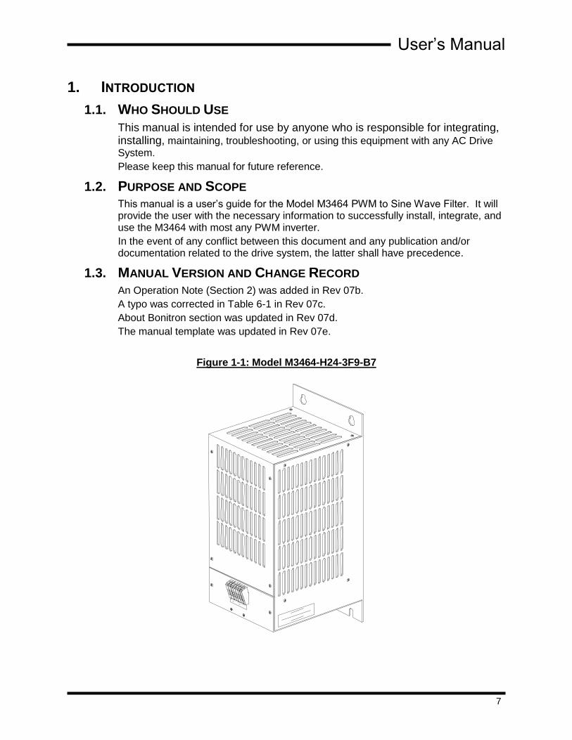
1.3. MANUAL VERSION AND CHANGE RECORD
An Operation Note (Section 2) was added in Rev 07b.
A typo was corrected in Table 6-1 in Rev 07c.
About Bonitron section was updated in Rev 07d.
The manual template was updated in Rev 07e.
Figure 1-1: Model M3464-H24-3F9-B7

M3464
8
1.4. SYMBOL CONVENTIONS USED IN THIS MANUAL AND ON
EQUIPMENT
Earth Ground or Protective Earth
AC Voltage
DC Voltage
DANGER!
Electrical Hazard - Identifies a statement that indicates a shock or electrocution hazard that must be avoided.
DANGER!
DANGER: Identifies information about practices or circumstances that can lead to personal injury or death, property damage, or economic loss.
CAUTION!
CAUTION: Identifies information about practices or circumstances that can lead to property damage, or economic loss. Attentions help you identify a potential hazard, avoid a hazard, and recognize the consequences.
CAUTION!
Heat or burn hazard - Identifies a statement regarding heat production or a burn hazard that should be avoided.

User’s Manual
9
2. PRODUCT DESCRIPTION
There are many applications in industry that utilize low horsepower, IGBT type, PWM Drives. Newer versions of these PWM drives typically have very fast transistor rise times and high carrier frequencies. When used with motors that have moderate to long cable lengths, high voltages caused by reflected waves might be present. Users of these drives may experience some problems with their systems due this condition. These problems may include any one or more of the following:
Premature motor winding failures
Premature motor bearing failures
Cable insulation failures
Drive ground fault problems
Noise interference in analog signal transducers
Noise interference in RF communication systems
One way to alleviate these problems is to use filtering. Bonitron, Inc. manufactures a line of PWM to Sine Wave Filter modules for use with low horsepower, IGBT, PWM drives. The Model M3464 series of PWM to Sine Wave filter modules is available for use with PWM drives rated for up to 575VAC. These modules are designed around Bonitron’s 3464F* series of PWM filter boards which can handle motor currents of up to 8 amps each. Multiple boards can be combined in parallel configurations to achieve higher motor current ratings as needed.
2.1. PART NUMBER BREAKDOWN
Figure 2-1: Example of Part Number Breakdown
BASE MODEL NUMBER The Base Model Number for a PWM to sine wave filter is M3464.
SYSTEM VOLTAGE RATING The System Voltage rating indicates the nominal AC voltage levels the filter is intended to support. A code letter indicates the system voltage.
MODEL NUMBER
CURRENT RATING
FILTER BOARD TYPE
CHASSIS STYLE
SYSTEM VOLTAGE
M3464 2F9 B7 H 016
OPERATION NOTES
LD

M3464
10
Table 2-1: System Voltage Rating Codes
SYSTEM VOLTAGE
RATING CODE NOMINAL AC VOLTAGE
U 115VAC Line
L 230VAC Line
E 380VAC Line
H 460VAC Line
C 575VAC Line
CURRENT RATING The Current Rating indicates the maximum current which may be safely handled by the M3464 PWM to sine wave filter unit. The rating is directly represented by a 3-digit number. For example, the Current Rating for a 16Amp unit is 016. The Current Rating is derived using 8kHz carrier. De-rating must be done at lower carrier frequencies.
FILTER BOARD TYPE The type of filter board used is denoted by a 2-character code as shown below. If multiple boards are used the number of boards used will precede the board number (i.e. if a module uses 2 3464F9 boards then the code will be 2F9).
Table 2-2: Filter Board Type Codes
FILTER BOARD CODE FILTER BOARD TYPE
F7 3464F7 board – L/C-Wye, 230V, 4A, 10% duty @ 2 minutes ON, 4kHz min, removable plugs
F9 3464F9 board – L/C-Wye, 460V, 8A @8kHz, removable plugs
FD Component on chassis construction – L/C-Delta. See Ratings Table in Section 6
FY Component on chassis construction – L/C-Wye. See Ratings Table in Section 6
CHASSIS STYLE There are several types of chassis available for use with the M3464 PWM to Sine Wave Filter:
Table 2-3: Chassis Style Codes
CHASSIS CODE CHASSIS
L2 Open chassis L-bracket for 3464F7 boards
L3 Open chassis L-bracket for 3464F9 boards
B4 Tall NEMA-1 enclosure (17.75”H x 4”W x 9”D)
B7 Tall NEMA-1 enclosure (17.75”H x 7”W x 9”D)
M3 Short NEMA-1 enclosure (12.75”H x 3”W x 9”D)
M4 Short NEMA-1 enclosure (12.75”H x 4”W x 9”D)
M7 Short NEMA-1 enclosure (12.75”H x 7”W x 9”D)
User’s Manual
11
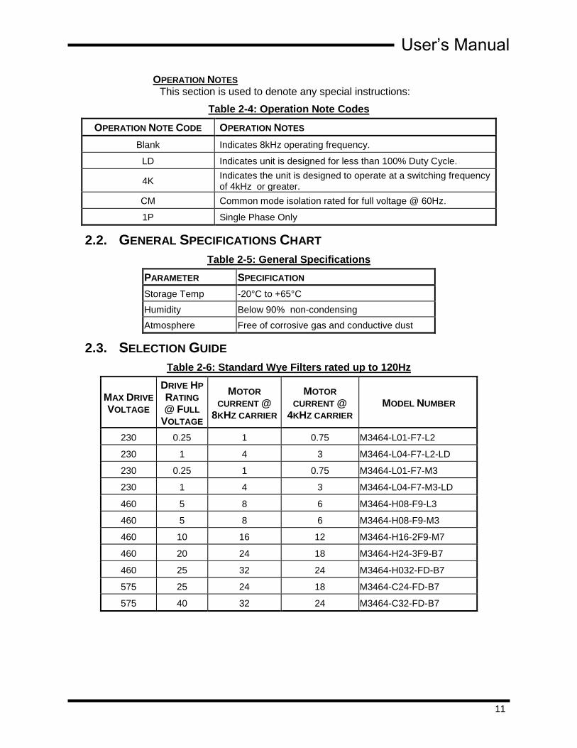
OPERATION NOTES This section is used to denote any special instructions:
Table 2-4: Operation Note Codes
OPERATION NOTE CODE OPERATION NOTES
Blank Indicates 8kHz operating frequency.
LD Indicates unit is designed for less than 100% Duty Cycle.
4K Indicates the unit is designed to operate at a switching frequency of 4kHz or greater.
CM Common mode isolation rated for full voltage @ 60Hz.
1P Single Phase Only
2.2. GENERAL SPECIFICATIONS CHART
Table 2-5: General Specifications
PARAMETER SPECIFICATION
Storage Temp -20°C to +65°C
Humidity Below 90% non-condensing
Atmosphere Free of corrosive gas and conductive dust
2.3. SELECTION GUIDE
Table 2-6: Standard Wye Filters rated up to 120Hz
MAX DRIVE
VOLTAGE
DRIVE HP
RATING
@ FULL
VOLTAGE
MOTOR
CURRENT @
8KHZ CARRIER
MOTOR
CURRENT @
4KHZ CARRIER MODEL NUMBER
230 0.25 1 0.75 M3464-L01-F7-L2
230 1 4 3 M3464-L04-F7-L2-LD
230 0.25 1 0.75 M3464-L01-F7-M3
230 1 4 3 M3464-L04-F7-M3-LD
460 5 8 6 M3464-H08-F9-L3
460 5 8 6 M3464-H08-F9-M3
460 10 16 12 M3464-H16-2F9-M7
460 20 24 18 M3464-H24-3F9-B7
460 25 32 24 M3464-H032-FD-B7
575 25 24 18 M3464-C24-FD-B7
575 40 32 24 M3464-C32-FD-B7

M3464
12
2.4. GENERAL PRECAUTIONS AND SAFETY WARNINGS
DANGER!
H I G H V O L T A G E S M A Y B E P R E S E N T !
N E V E R A T T E M P T T O O P E R A T E T H I S P R O D U C T W I T H T H E
E N C L O S U R E C O V E R R E M O V E D !
N E V E R A T T E M P T T O S E R V I C E T H I S P R O D U C T W I T H O U T
F I R S T D I S C O N N E C T I N G P O W E R T O A N D F R O M T H E U N I T !
AL W A Y S A L L O W A D E Q U A T E T I M E F O R R E S I D U A L V O L T A G E S
T O D R A I N B E F O R E R E M O V I N G T H E E N C L O S U R E C O V E R .
F AI LURE TO HEED THESE W ARNI NGS M AY RESULT
I N SERIOUS BO DILY I NJURY O R DEATH !
CAUTION!
T H I S P R O D U C T W I L L G E N E R A T E H I G H A M B I E N T
T E M P E R A T U R E S D U R I N G O P E R A T I O N .
T H I S P R O D U C T S H O U L D B E I N S T A L L E D A C C O R D I N G L Y O N
N O N - F L A M M A B L E S U R F A C E S W I T H C L E A R A N C E S O F A T
L E A S T T W O I N C H E S I N A L L D I R E C T I O N S .
AL W A Y S A L L O W A M P L E T I M E F O R T H E U N I T T O C O O L
B E F O R E A T T E M P T I N G S E R V I C E O N T H I S P R O D U C T .
B E F O R E A T T E M P T I N G I N S T A L L A T I O N O R R E M O V A L O F
T H I S P R O D U C T , B E S U R E T O R E V I E W A L L D R I V E A N D / O R
R E S I S T I V E L O A D D O C U M E N T A T I O N F O R P E R T I N E N T
S A F E T Y P R E C A U T I O N S .
I N S T A L L A T I O N A N D / O R R E M O V A L O F T H I S P R O D U C T
S H O U L D O N L Y B E A C C O M P L I S H E D B Y A Q U A L I F I E D
E L E C T R I C I A N I N A C C O R D A N C E W I T H N A T I O N A L
E L E C T R I C A L C O D E O R E Q U I V A L E N T R E G U L A T I O N S .
ANY QUESTIONS AS TO APPLICATION, INSTALLATION, OR SERVICE SAFETY
SHOULD BE DIRECTED TO THE EQUIPMENT SUPPLIER.

User’s Manual
13
3. INSTALLATION INSTRUCTIONS
3.1. ENVIRONMENT Units should be installed in area with 50ºC or lower ambient.
3.2. UNPACKING
Upon receipt of this product, please verify that the product received matches the product that was ordered and that there is no obvious physical damage to the unit. If the wrong product was received or the product is damaged in any way, please contact the supplier from which the product was purchased.
3.3. MOUNTING Units should be mounted with minimum of 2” clearance on sides and 4” clearance on top and bottom.
Refer to Section 6.4 for mounting dimensions.
3.4. Wiring and Customer Connections
3.4.1. TERMINAL LAYOUT
Figure 3-1: Typical Field Connections
Dwg: 070095 Rev: 20070404

M3464
14
3.4.2. SYSTEM WIRING
Figure 3-2: Typical System Interconnections
3.4.2.1. GROUNDING REQUIREMENTS
Earth ground is provided and is absolutely needed for common mode filtering.
Dwg: 070094 Rev: 20070404

User’s Manual
15
3.5. TYPICAL CONFIGURATIONS
3.5.1. FILTER BASICS
The M3464 series of PWM Sine Wave Filters provide filtering for either single-phase applications or three-phase applications with either delta or wye output configurations. The filters provide a low pass filter with a cut-off frequency of 120Hz. These filters use low loss line reactors to minimize noise and losses. In addition to limiting the dV/dt rise times, the M3464 Filter also filters out the carrier frequency. Figure 3-3 shows both the PWM Drive and M3464 Filter output waveforms at 8kHz carrier frequency (60Hz fundamental).
Figure 3-3: Drive and Filter Output Signal Comparison
Filter Output
Drive Output
Figure 3-4: Motor Current and Voltage at 8kHz carrier frequency
Motor Current
Motor Voltage

M3464
16
Figure 3-5: Motor Current and Voltage at 4kHz carrier frequency
Motor Current
Motor Voltage
Figure 3-6: Motor Current and Voltage at 2kHz carrier frequency
Motor Current
Motor Voltage
User’s Manual
17
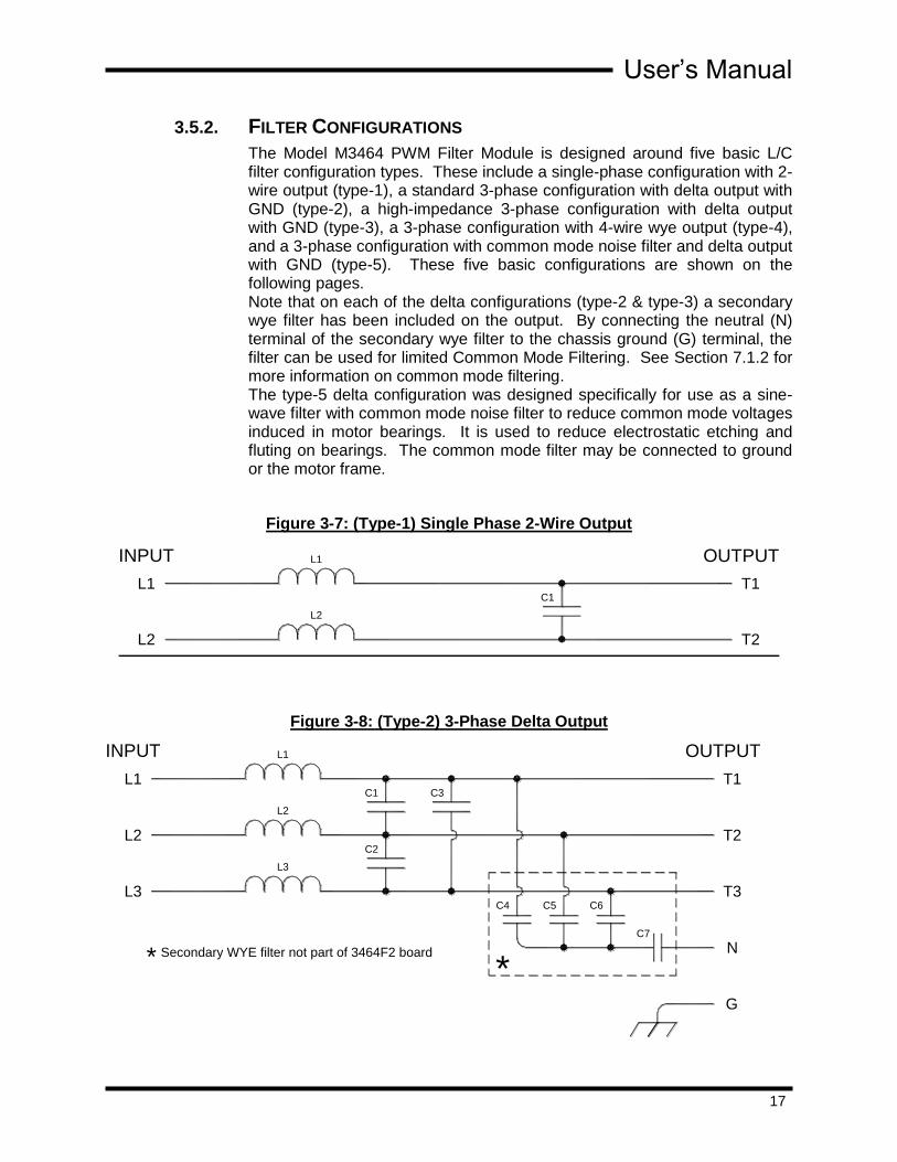
3.5.2. FILTER CONFIGURATIONS
The Model M3464 PWM Filter Module is designed around five basic L/C filter configuration types. These include a single-phase configuration with 2-wire output (type-1), a standard 3-phase configuration with delta output with GND (type-2), a high-impedance 3-phase configuration with delta output with GND (type-3), a 3-phase configuration with 4-wire wye output (type-4), and a 3-phase configuration with common mode noise filter and delta output with GND (type-5). These five basic configurations are shown on the following pages. Note that on each of the delta configurations (type-2 & type-3) a secondary wye filter has been included on the output. By connecting the neutral (N) terminal of the secondary wye filter to the chassis ground (G) terminal, the filter can be used for limited Common Mode Filtering. See Section 7.1.2 for more information on common mode filtering. The type-5 delta configuration was designed specifically for use as a sine-wave filter with common mode noise filter to reduce common mode voltages induced in motor bearings. It is used to reduce electrostatic etching and fluting on bearings. The common mode filter may be connected to ground or the motor frame.
Figure 3-7: (Type-1) Single Phase 2-Wire Output
Figure 3-8: (Type-2) 3-Phase Delta Output
TYPE-1: SINGLE PHASE CONFIGURATION
L2
L1
L2
C1
INPUT L1
T2
T1
OUTPUT
TYPE-2: 3Ø DELTA CONFIGURATION (W/SECONDARY WYE)
L3
L3
L2
L1
L2
INPUT L1
T3
T2
T1
OUTPUT
C2
C1 C3
C4
C7
*
C6C5
N
G
Secondary WYE filter not part of 3464F2 board*

M3464
18
Figure 3-9: (Type-3) High Impedance, 3-Phase Delta Output
Figure 3-10: (Type-4) 3-Phase Wye Output
Figure 3-11: (Type-5) 3-Phase Delta with Secondary Wye Output
OUTPUTINPUT
L2
L3
L3
L1
L2
L1
L6
L5
L4
T2
T3
T1C1 C3
C2
G
N
C5C4 C6
C7
Secondary WYE filter not part of 3464F3 board* *
TYPE-3: HIGH-Z, 3Ø DELTA CONFIGURATION (W/SECONDARY WYE)
T1L1
Capacitor C4 not used on 3464F5 board
L2
L3
L3
*
L2
C1 C2
T3
*C4
C3
N
T2
L1INPUT OUTPUT
TYPE-4: 3Ø WYE CONFIGURATION
TYPE-5: 3Ø DELTA CONFIGURATION (W/SECONDARY WYE)
L3
L2
L3
L2
INPUT
L1
L1
C3C1
C5
C2
C4
F/G
C6
C7N
T3
T2
OUTPUT
T1
L4B
L4C
L4A
R1
MOTOR FRAMEOR GROUND
User’s Manual
19
4. OPERATION
4.1. FUNCTIONAL DESCRIPTION Bonitron’s 3464 Filter series is designed to ‘smooth’ the voltage and current to the connected motor load of a variable frequency drive. Each time the drive inverter switches, the output voltage swings quickly to the DC positive and negative rails, creating a very fast changing square wave.
L/C PWM filters operate using inductance to slow the rate of current change, and capacitance to smooth out the voltage waveform. The fast switching, PWM square wave will be smoothed into a sinusoidal waveform suitable for the motor and connecting wires.
4.2. FEATURES All units use L/C type filtering.
Units are available for single phase and 3-phase delta or wye configurations.
Units are designed to handle fundamental frequencies up to 120Hz. Modules designed for higher fundamental frequencies are possible.
Can be used at any V/Hz ratio.
Units are available for use with drives utilizing carrier frequencies as low as 2kHz although 4kHz or higher is preferred.
Individual units using circuit board construction are available at ratings of up to 8 amps each at up to 460VAC input. These units can be added together in parallel configurations to achieve higher current ratings as needed. Units using component-on-chassis construction are not limited to the 8 amp individual unit rating. These units can be designed for specific applications and requirements as needed.
Available in open-chassis or NEMA-1 packages.
Modules using circuit board construction can also be used with standard delta-wye transformers for common mode filtering which helps to prevent early bearing failure due to pitting. See Bonitron’s Model M3664 Common Mode Filter modules.
4.2.1. ALL M3464 PWM SINE WAVE FILTER MODULES SHARE THE
FOLLOWING CHARACTERISTICS:
L/C type filtering
Designed to handle fundamental frequencies up to 120Hz
Can be used at any V/Hz ratio.
Units are available for use with drives utilizing carrier frequencies as low as 2kHz.
Units can be added in parallel configurations to achieve higher current ratings as needed.
Filter modules are rated for continuous usage (100% duty @ 8kHz carrier frequency) unless otherwise specified.
For configuration types, see Section 3.5 in this manual.

M3464
20
4.3. STARTUP 1. Ensure phasing to motor is correct to prevent backwards operation.
2. Set drive carrier for 8kHz.
3. Start drive.
4. With o-scope, monitor link between drive and filter for excessive currents.
5. With o-scope, monitor filter output voltage.
6. Check the noise problem that instigated the filter purchase.
4.4. OPERATIONAL ADJUSTMENTS There are no adjustments or calibrations for this unit.

User’s Manual
21
5. MAINTENANCE AND TROUBLESHOOTING
Repairs or modifications to this equipment are to be performed by Bonitron approved personnel only. Any repair or modification to this equipment by personnel not approved by Bonitron will void any warranty remaining on this unit.
5.1. MAINTENANCE ITEMS There is no periodic maintenance to perform on standard filters.
Note: Special filters may include a fan for cooling and unit should be cleaned as needed.
5.2. SYMPTOMS AND CURES
Table 5-1: Symptoms and Cures
SYMPTOM CURE
Overheating
Raise carrier frequency
Check motor current
Check fan, if equipped
Excessive noise Raise carrier frequency
Excessive drive currents Raise carrier frequency
5.3. DETAILED TROUBLESHOOTING
Table 5-2: Detailed Troubleshooting
PROBLEM RESOLUTION
Filter does not solve noise problems Common mode filtering may be needed

M3464
22
This page intentionally left blank.

User’s Manual
23
6. ENGINEERING DATA
6.1. WATT LOSS Typically 95% efficient at full load.
6.2. RATINGS CHARTS
Table 6-1: Ratings and Specifications
MO
DE
L
NU
MB
ER
V(M
AX)
I (C
ON
T.)
HP
@ R
AT
ED
VO
LT
AG
E
I (S
UR
GE)
MIN
IMU
M
CA
RR
IER
FR
EQ
.*
RE
CO
MM
EN
DE
D
CA
RR
IER
FR
EQ
.
CF
IG T
YP
E
BO
AR
D
CH
AS
SIS
SP
EC
IAL
RA
TIN
GS
M3464-L001-F7-L2-1P 230V 1 1A .25 200% 4kHz 8kHz 1 3464F7 L-bracket
Capable of 1A
Continuous duty
M3464-L001-F7-L2-LD 230V 3 1A .25 200% 4kHz 8kHz 4 3464F7 L-bracket
Capable of 1A
Continuous duty
M3464-L004-F7-L2-LD 230V 3 4A 1 200% 4kHz 8kHz 4 3464F7 L-bracket 10% Duty @ 2
minutes ON
M3464-L001-F7-M3-LD 230V 3 1A .25 200% 4kHz 8kHz 4 3464F7 NEMA-1
Capable of 1A
Continuous Duty
M3464-L004-F7-M3-LD 230V 3 4A 1 200% 4kHz 8kHz 4 3464F7 NEMA-1 10% Duty @ 2
minutes ON
M3464-H008-F9-M3 460V 1 8A 5 200% 4kHz 8kHz 4 3464F9 NEMA-1 5A @4kHz
M3464-H008-F9-L3 460V 3 8A 5 200% 4kHz 8kHz 4 3464F9 L-bracket 5A @4kHz
M3464-H016-2F9-B4 460V 3 16A 10 200% 4kHz 8kHz 4 3464F9 NEMA-1 10A @4kHz
M3464H024-3F9-B7 460V 3 24A 20 200% 4kHz 8kHz 4 3464F9 NEMA-1 18A @4kHz
M3464-H032-FD-B7 460V 3 32 25 200% 4kHz 8kHz 4 N/A NEMA-1 24A @4kHz
M3464-C024-FD-B7 575V 3 24A 25 150% 4kHz 8kHz 2 N/A NEMA-1 18A @4kHz
M3464-C032-FD-B7 575V 3 32A 40 150% 4kHz 8kHz 2 N/A NEMA-1 24A @4kHz
For optimal performance use the highest available carrier frequency. Testing done at 60Hz fundamental. See Special Ratings in Table 6-1 above.
6.3. FUSE/CIRCUIT BREAKER SIZING AND RATING Fusing is not included.

M3464
24
6.4. DIMENSIONS AND MECHANICAL DRAWINGS
Figure 6-1: “L2” Chassis (for 3464F7) – Type 4
Dwg: 020034 Rev: 20020123

User’s Manual
25
Figure 6-2: “L3” Chassis for 3464F9 – Type 6
34
64
F9
A 3
-P
HA
SE
FILT
ER
By B
ON
IT
RO
N
Dwg: 070072 Rev: 20070326

M3464
26
Figure 6-3: “M#”-Type and “B#”-Type Enclosures
Table 6-2: Enclosure Dimensions
CHASSIS DIM.A DIM.B DIM.C DIM.D DIM.E DIM.F DIM.G
M3
12.75
3.00 1.50 N/A
12.00 10.50 1.13 M4 4.00 1.25 1.75
M7 7.00 1.00 5.00
B4 17.75
4.00 1.25 1.75 16.75 15.00 1.38
B7 7.00 1.00 5.00
TERMINAL STRIP
B
D
.28 .28
.75
SIZED FOR 1/4" BOLTS OR STUDS
G
8.50
7.70
F EA
L1 L2 L3 T1 T3T2 G
PWM INPUT SINE OUTPUT
(approx.)
C
N
Dwg: M3464_chx_out Rev: 20020429
User’s Manual
27
7. APPENDICES
7.1. APPLICATION NOTES
7.1.1. CARRIER FREQUENCY
One trick to good drive system performance is using the proper carrier switching frequency. Tradeoffs are made in power losses, voltage drops, audible noise, and heating. Knowing what these trade-offs are can help determine where to set the carrier frequency for your application. See Figures 7-8, 7-9, and 7-10 for typical waveforms at different carrier frequencies.
THE DRIVE Most of today’s inverters have the ability to change the PWM switching frequency. This frequency can be set to maximize performance for any application. Typically drives are factory set for a low carrier of 4kHz, and are Hp rated at this carrier frequency. Increasing this frequency will de-rate the drive Hp capability so it is typically not recommended by the drive manufacturer. Basic rule: Lower carrier is better due to less heating in drive from switching losses. Increasing carrier frequency de-rates inverter. If using a PWM filter, lowering carrier too much will cause excessive drive currents and oscillations between filter and drive.
THE MOTOR There are many different types of motors. Many new motors are “inverter duty” rated which means they have special insulation and bearings to allow long term use with fast switching PWM inverters. These motors should not need a filter to increase their life, but may still need a filter because noise can still be generated between the inverter and motor. This noise acts somewhat like an AM radio transmitter and can be seen by electronic equipment in the near vicinity, which causes all kinds of ghost problems. Older motors are not rated for the high voltage spikes and they can burn up windings, or pit the bearings quickly. A PWM filter can be used to keep the motor from burning up prematurely as well as stopping radiated noise. Basic rule: If motor is “inverter duty rated” a higher carrier is better due to less heating in motor and less audible noise. If not “inverter duty” rated, more switching can cause more voltage spikes and may actually decrease motor life.
THE FILTER Bonitron designs and builds filters that strip most of the high frequency out of the motor leads, eliminating premature motor failures associated with using new PWM inverters on old motors, and non “inverter duty” rated motors. The filter also slows down the rise time of the voltage changes from the PWM inverter, which in turn decreases the radiated or conducted noise through the motor cables. Basic rule: Higher carrier is better due to lower current ripple which reduces heating in filter, as well as provides a smoother waveform to the motor.

M3464
28
SUMMARY Carrier frequency has a direct effect on heating of all three components. Compromise between drive, motor, and filter needs should ultimately determine carrier frequency. NOTE: The output waveform does not have to be perfectly smooth to solve noise problems.
7.1.2. COMMON MODE FILTERING
COMMON MODE NOISE New high efficiency drive systems exhibit fast rise times between earth ground and system potential. This “common mode noise” can be seen with an oscilloscope, and is seen by any connected equipment, sometimes having a negative affect. Anything connected will see this fast changing voltage, and the internal capacitance to earth may cause induced currents where they are not expected or wanted. Looking between earth and any motor phase will show this high fast switching voltage.
EFFECTS ON MOTOR For motors these fast voltage rise times can cause capacitive coupling between the windings and the rotor. If the motor shaft is at a different potential, this built up voltage on the rotor will arc to ground through the metal bearings as they rotate and bounce. This arcing will cause pitting, which in turn increases the arcing, which in turn causes premature bearing failure. Testing shows that faster rise times and higher carrier frequencies tend to cause more build up and arcing. Testing also shows that typical 3- phase PWM filtering is not enough to stop this noise.
FILTERING Typical PWM filtering will strip out the carrier frequency from the fundamental motor voltage to the windings, but they will not diminish common mode noise. If bearing pitting is occurring, then common mode filtering must be done. To remove 100% of this noise an isolation transformer must be used. However, by adding some capacitance between the PWM filters wye connection and earth, enough common mode filtering can be accomplished to increase motor life.
SIDE AFFECTS Side effects of common mode filtering are increased inverter output currents, and decreased fundamental current rating of PWM filter. Capacitance and resistance can be used to tailor the amount of filtering, and is to be done at the field level.
FINE TUNING Typical capacitance values are .01-.1uf and resistor values from 100-1kOhms. Cap value affects frequency response, and resistor value affects amount of filtering. The higher the cap value the more power will have to be burned off in the resistor. Using too low of resistor ohmic value can burn up the series capacitor due to excessive currents.

User’s Manual
29
7.1.3. VARIOUS TYPES OF NOISE WITH PWM INVERTERS AND MOTORS
Today’s PWM drives are very energy efficient, and the common topology has become fairly simple to produce low cost drives. Variable frequency drives are becoming economical for use with many types of systems. One of the negative issues associated with using PWM drives is the noise emitted from them. This noise comes in a few different ways:
1. Common mode noise 2. Conducted switching noise 3. Electromagnetic interference (EMI) 4. Audible noise
7.1.3.1. COMMON MODE NOISE
Common mode noise from PWM drives is typically out of the audible range, and affects connected equipment in various ways, including causing erroneous signals which can cause false trips, lock ups, or incorrect information in digital systems. Common mode noise is essentially the result of ultra-fast rise times from fast voltage changes, which are capacitively coupled to earth ground through paths of unknown stray capacitance. This can be seen looking between earth ground and any point connected to the drive, including non-isolated peripheral equipment. Common mode noise is usually not associated with the carrier fundamental switching frequency, but rather the dV/dt of the rise and fall times of the switching frequency.
7.1.3.2. CONDUCTED NOISE
Conducted switching noise is caused by fast current changes, and is usually seen at the carrier frequency. Voltage drops can be caused by the inductive effect from these fast changing currents. With a rise time of 8ms (as seen in 60Hz power systems), a small inductance of a wire or circuit lane does not matter much, but with a rise time of 1us, (as seen in 8kHz carrier frequencies) the small inductor now shows an appreciable voltage drop. This voltage drop at the fast rise time can cause trouble if it is not known or compensated for. Special considerations must be given to grounding paths and special types of low inductance power connections. Long wire runs to the motor can cause larger drops and standing waves resulting in high peak voltages at the motor, which in turn causes insulation breakdown.
7.1.3.3. EMI NOISE
These fast changes in current also cause magnetic fields to occur, which causes EMI. Long wire runs act as antennas emitting signals in a range based on the rise times of the current. These emissions can be picked up by a common AM radio, or worse, a common circuit. The closer in proximity to this emission, the worse the effect. Replacing an old drive with a new drive can cause trouble where it never was seen before due to a different rise time in this current. A new switching component (IGBT) can have a faster turn on rate and change the Special shielded wire must be to decrease this effect on other equipment.

M3464
30
7.1.3.4. AUDIBLE NOISE
The magnetic field caused by the changing current can also cause physical movement when in close proximity to magnetic metals. This movement can often be heard, and is usually the carrier switching frequency of the drive.
In a typical PWM drive system the motor windings are used as the PWM filter. The inductance of the motor windings slows down the rate of current change, but the electromagnetic field that results not only moves the motor rotor, it also moves the windings and laminations. This movement causes audible noise.
This is somewhat backwards of a speaker in an audio system, where the windings are kept stationary and the diaphragm is free to move with changes in the magnetic field.. The diaphragm is connected to a cone that moves air. The windings may physically move some, but it is negligible compared to the affects of cone movement so we do not think about it.
In a motor, the winding load is the rotor. The rotor moves in rotation with the rotating magnetic field at the fundamental frequency, but rotor laminations and motor windings also move due to the magnetic field created by current changes at the switching frequency. If you were to remove the speaker cone, and dump 5hp (3750 watts) into the speaker coil, you would hear the coil move!
Older motors were wire wound and bundled together, which allows much movement when hit with fast current changes. Today’s PWM duty motors have heavier insulation ratings and are vacuum impregnated to decrease the amount of winding movement.
The audible sound can be heard in the drives capacitors or inductors, it can be heard in the wiring between the drive and the motor, but can usually best be heard in the motor windings. Since the most sensitive hearing range for most people is in the 1-4kHz range, typically the lower the carrier frequency, the louder the noise. For a fixed voltage and inductance, the lower carrier frequencies allow greater ripple currents, create greater magnetic changes, have greater physical affect on components, which causes more audible noise. As carrier frequencies increase, there is a drop off in peak current changes, and audible noise. As carrier frequencies approach 16kHz, the noise is greatly reduced due to small changes in current, decreased ability of components to physically respond to current change, and the frequency is getting out of human hearing range. The amount of noise heard is proportional to the frequency, the amount of current, the rate of current change, and the construction of the filter device (physical rigidity of windings).
When the drive DC bus drops, it begins to compensate by increasing the pulse width of the carrier. This increase in PW allows more current to build up in the motor windings, which causes more audible noise. When a drive changes torque, the audible sound changes as a result of the current intensity. More current causes more magnetism, which in turn causes more audible noise. If the drive DC bus drops due to a sag in line voltage, there is also an audible affect on the incoming feed Magnetics in that the current changes shape and increases to maintain

User’s Manual
31
the same power output. The hum heard at the 50 or 60 cycle rate will increase.
When ramping up a motor with a fixed carrier PWM drive, the audible frequency does not change, but the intensity and tone does. The sound heard is mostly the windings at the switching frequency, not the motor running at the fundamental frequency.
Some drives do change their carrier frequencies based on motor speed. These changes can be heard. Changes in load or changes in drive bus voltage will cause a change in intensity or tone, or even frequency. While the sound may make it seem like the motor changes speed, the sound is actually the drive trying to keep the motor speed constant. When a change in parameters occurs and a change in audible noise does not, one could assume the drive is not compensating.
In all these cases, A PWM filter can be used to “trap” these switching currents, or hold down the voltage changes, producing a smooth waveform to the motor to decrease or even eliminate the noise problems, but the noise will now be seen in the filter.
For complete common mode noise reduction it is necessary to use an isolation transformer with an output wye configuration and electrostatic shielding. For all other types of noise, an LC filter can be used, designed to handle the fast rise times from the VFD outputs. One problem remains. Now the audible noise will be heard in the filter.

M3464
32
This page intentionally left blank.
User’s Manual
33
NOTES

M3464
34


D_M3464_CMAN_VALL_07e 04/04/2014
521 Fairground Court ● Nashville, TN 37211 ● USA
Tel: (615) 244-2825 ● Fax: (615) 244-2833 ● Web: www.bonitron.com ● Email: [email protected]