Embed Size (px)
Citation preview
Model~BasedKinematic Simulation
ElishaSacks*ComputerScienceDepartment
PrincetonUniversityPrinceton,NJ 08544
Leo JoskowiczIBM T.J. WatsonResearchCenter
P.O. Box 704Yorktown Heights,NY 10598
June 18, 1992
Abstract
We presentapracticalsimulationprogramfor rigid part mechanisms,suchas feeders,locks, andbrakes.The programperformsakinematicsimulationofthe behaviorproducedby part contactsand input motions along with a dy-namicalsimulationof the behavior producedby gravity, springs,and friction.It describesthe behaviorin acompact,symbolic format andwith a realistic,three-dimensionalanimation. The program is more efficient and informativethan traditionalsimulators. It examinesroughly 1/6 as many degreesof free-dom becausethe kinematicsmodule eliminates the blocked ones. It spendslittle time on coffision detectionbecausethe kinematicsmodule precomputesthe configurationswhere parts collide, It covers more mechanismsthan dopreviousmodel-basedsimulators,generatesfuller behavioraldescriptions,andexploits kinematicsmore fully. It usesa simple model of dynamicsthat cap-turesthe steady-stateeffect of forceswithout the conceptualandcomputational
cost of dynamical simulation. We demonstratethat our simulation algorithm
capturesthe workingsof mostmechanismsby surveying2500 mechanismsfroman engineeringencyclopedia.
*This researchis supportedby the National ScienceFoundationunder grant No. IRI—9008527
and by an IBM grant.
109
1 Introduction
This paperpresentsresearchin automating the analysis of rigid part mechanisms, suchas feeders,locks, and brakes. In previouswork, we developeda kinematic analysisprogramthat takesageometricdescriptionof the partsof amechanismandgeneratesa symbolic descriptionof the spaceof behaviorsfor all possibleinput motions. Wenow describeaprogramthat simulatestheactual behaviorof amechanismfor agiveninput motion. The program simulatesthe effects of part contacts, input motions,
and internal forces, such as gravity and friction. It generatesa compact, symbolic
behavioral description and a realistic, three-dimensionalanimation. The simulation
algorithm covers most mechanismsin an engineeringencyclopedia, including ones
with complexpart shapes,varying part contacts,and multiple input motions.
Traditional mechanismsimulators,such as ADAIVIS, derive the Newton-Eulerorthe Lagrangeequationsof motion, a mixture of algebraicanddifferential equations,and numerically integratethem for a given initial condition [4]. They always con-sider six degreesof freedom per part, which yields complicatedequationsin manyvariables. The usermust infer the qualitative workings of the mechanismfrom thedetailednumericaloutput. Somesimulatorsassumethat all contactsare permanent,
hencethat the equationsare fixed and independentof the shapesof the parts (as inlinkages). Others perform an expensivepart collision test at eachintegration stepand reformulatethe equationsafter eachcontactchange.
Recentmodel-basedsimulatorsaddresssomeof theselimitations by incorporatingsymbolic kinematicanalysisinto dynamicalsimulatorsand by producingbehavioralsummaries[2, 3, 5]. However, they imposerestrictionson the part geometryandmechanismstructure,havelimited interpretationcapabilities,and tendto be fragileand inefficient.
Our researchadvancesthe stateof the art in mechanismsimulationby exploitingknowledgeabout the structureand function of mechanisms.The ways that mech-anismsare designedconstrainthe shapes,motions, and interactionsof their parts.We identify constraintsthat cover mostmechanism,yet allow efficient analysis. Theprogramhandlesfeasible mechanisms:linkages, fixed-axesassemblies,or fixed-axessubassembliesconnectedby linkages.Linkagesareone-dimensionalrodspermanentlyconnectedby standardjoints. Fixed-axesassembliesconsist of 2.5D parts that movealongfixed spatialaxes.The programusesasimplemodel of dynamicsthat capturesthe steady-stateeffect of forces without the conceptualand computationalcost ofdynamicalsimulation.
Our programcoversmoremechanismsthan do previousmodel-basedsimulators,generatesfuller behavioral descriptions,and exploits kinematicsmore fully. It ismore efficient than traditional simulators. It examines roughly 1/6 as many degrees
of freedombecausethe kinematicsmodule eliminatesthe blocked ones. It spendslittle time on collision detection becausethe kinematics module precomputestheconfigurationswherepartscollide. It generatessymbolicoutput as well as numericalsimulations. It complementsour previousprogram: it is fast andspecific, whereas
110

that program is slowerand comprehensive.The program derives the behaviorof a mechanismby kinematic simulationwith
simple dynamics. Kinematic simulation infers the effect of input motions on themotion of the parts of the mechanism,using the physical principle that two rigidobjects cannot be in the sameplace at the sametime. Simple dynamicsmodelsforces and friction. A force acts on a part along a translationalaxis or around arotational axis, imparting a constantlinear or angularvelocity. The velocity dropsto zerowhen the force stops acting; there is no inertia. Collisions amongparts areinelastic. Friction constrainsparts that touch along asticky faceto move in tandemalong axesparallelto that face.
Simpledynamicsis aqualitativetheoryof steady-statemotion thatabstractsawaytransientacceleration.Applying a constantforce to an object actually acceleratesitto a terminal velocity at which friction balancesthat force, but simple dynamicsassumesthat it reachesterminal velocity instantaneously.Ignoring transientsmakessimpledynamicssimpleandefficient, but sacrificesthepredictivepowerof Newtonianmechanics. It suffices for mechanismsthat rely on forces to push parts in certaindirections. It cannothandlemechanismsin which delicatebalancesof forces,transientbehavior,or time varyingforcesplay amajor role. The tradeoffis worthwhilebecausesimple dynamicsadequatelycoversmostmechanisms.
We formalizekinematic simulationwithin the configuration space(CS) represen-tation of mechanicalengineering. Intuitively, the CS of a mechanismis the spaceof non-overlappingconfigurationsof its parts. It partitions into regions of uniformpart contactsseparatedby boundarieswhere part contactschange,called a regiondiagram. Eachregion is specifiedby equalityand inequality constraintsthat expresspart contacts. The regions define the operating modes of the mechanism. Modetransitionsoccur whenthe configuration shifts betweenadjacentregions. Each paththrough CS definesapossiblebehaviorof the mechanism.The regionsthat the pathgoesthrough provide a symbolic description of the behavior.
The kinematicsimulation programtracesthe path that the mechanismtraversesunder agiven input motion. It startsfrom theregion that containsthe initial mecha-nism configuration,constructsthe segmentof the path lying in that region, finds thenext region that the pathenters,andrepeatsthe process.It constructsthe segmentsby propagatingthe input motion through the constraintsimposedby the part con~~tacts within the regions. The simulationendswhen the mechanismblocks or after auser-specifiedtime allotment.
We implementsimple dynamicsforcesas externalmotionsakin to input motions,but actinginfinitely faster. The differencein time scalecapturesthe role of forcesinmostmechanisms.Gravity quickly dropsunsupportedobjectsontothe objectsbelow.A spring quickly pushesa mobile object againsta fixed object then maintainsthecontact. We assumethat at most oneexternalmotion actson a part at any time. Ifan input motion andan external motion both act on apart, the input motion occurs.We implement friction as constraintsakin to kinematic constraints.
Figure 1 shows the relationshipbetweenthe kinematic simulation program and
111
mechanismstructure
initial configuration
Imodeling
subassemblyanalysis
znput motzonsanalysis simulation H~ forcestime allotnient
region diagram ~D animationsymbolicdescription
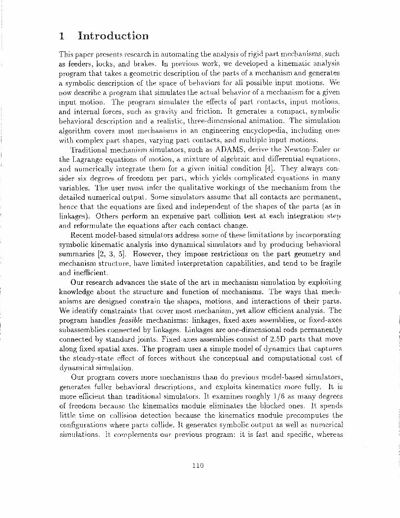
Figure 1: Mechanismanalysisflowchart.
our previouskinematicanalysisprogram[6]. The inputsto bothprogramsincludethestructureand initial configuration of a mechanism.The programssharea modelingmodule,which decomposesthe mechanisminto subassembliesandfinds their degreesof freedom,and a subassemblyanalysismodule,which constructsthe subassemblyregion diagrams. The kinematic analysisprogram constructsthe mechanismregiondiagramfrom the subassemblydiagramsandthe initial configuration. The kinematicsimulationprogramtakesan input motion, internal forces, andtime allotmentas ad-ditional inputsandgeneratesa symbolicdescriptionandan animationof the ensuingbehavior.
2 Kinematic simulation of a feeder
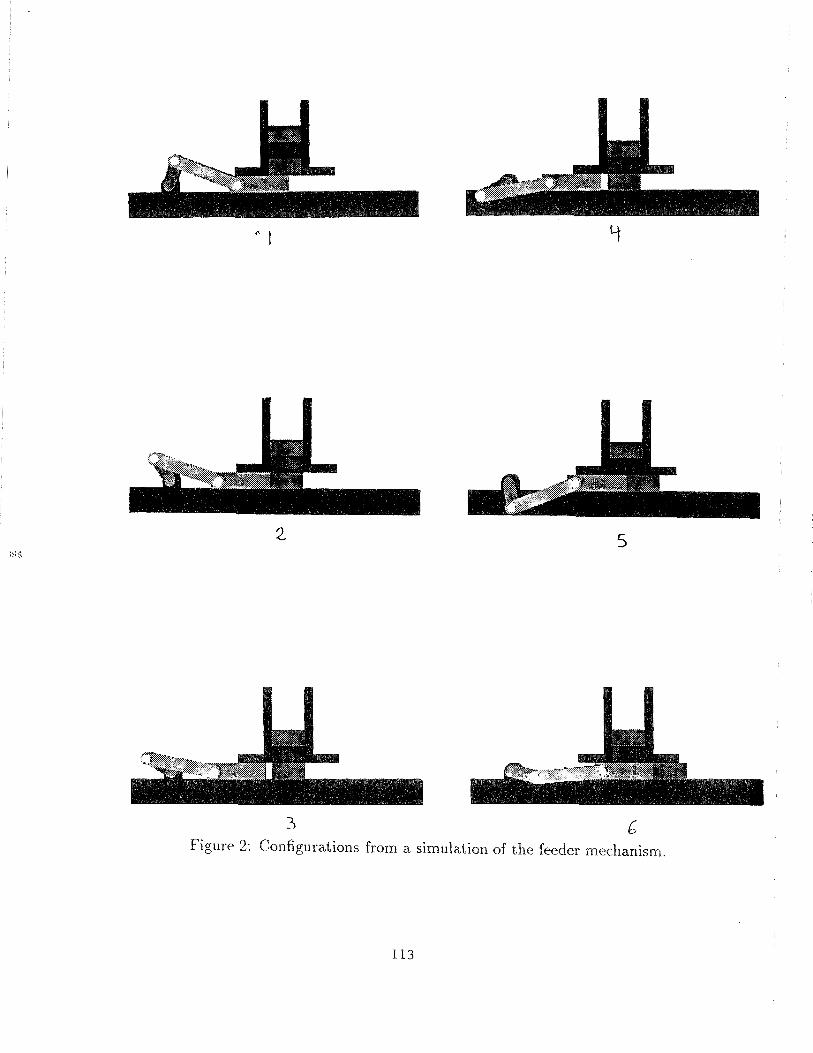
We illustrate the kinematic simulation program on a mechanismthat feeds blocksfrom astackontoa processingtable (Figure 2). The input motion rotatesthe drivershaft, which movesthe link, which slides the piston left and right. Each time thepiston slides left, oneblock drops onto the table dueto gravity. Each time it slidesright, it pushesthe bottom block onto the table.
The programinputsarethe part specificationsandinitial configurations,thegrav-itational forceson the blocks,andthemotion “driver rotatescounterclockwise”.Eachpart is specifiedby its shape,coordinates,andmotion type: fixed, fixed-axes,or link-age. Fixed-axespartsmovealong fixed spatial axes,whereaslinkage partsneednot.
112
:3
Figure 2: Configurationsfrom a simulation of the feedermechanism.
9
2. 5
113
segment1:(driving-motion (driver cd))
(drives (driver cd) ((piston xp)))(driver rotates(cd 0 2.1268))(piston translates (xp 10 5))(blocki stationary (xbl 12) (ybi 1))(block2 stationary (xb2 12) (yb2 3))(block3 stationary (xb3 12) (yb3 5))
segment2:(driving-motion (block3 yb3))(drives (block3 yb3)
((blocki ybl) (block2 yb2)))(driver stationary(cd 2.1268))(piston stationary (xp 5))(blocki translates(ybi 1 -1) (xbl 12))(block2 translates(yb2 3 1) (xb2 12))(block3 translates(yb3 5 3) (xb3 12))
segment 3:(driving-motion (driver cd))(drives (driver cd) ((piston xp)))(driver rotates(cd 2.1268 3.1416))(piston translates(xp 5 4))
(blocki stationary(xbl 12) (ybi -1))(block2 stationary (xb2 12) (yb2 1))(block3 stationary (xb3 12) (yb3 3))
segment4:(driving-motion (driver cd))(drives (driver cd) ((piston xp)))(driver rotates(cd -3.1416-2.1268))(piston translates(xp 4 5))(blocki stationary (xbl 12) (ybi -1))(block2 stationary (xb2 12) (yb2 1))(block3 stationary(xb3 12) (yb3 3))
segment 5:
(driving-motion (driver cd))(drives (driver cd) ((pistonxp)))(drives (piston xp) ((blocki xbl)))(driver rotates(cd -2.1268-0.7227))(piston translates(xp 5 9))(blockl translates(xbl 12 16) (ybi -1))(block2 stationary (xb2 12) (yb2 1))(block3 stationary(xb3 12) (yb3 3))
segment6:(driving-motion (driver cd))(drives (driver cd) ((pistonxp)))(drives (pistonxp) ((blockl xbl)))(driver rotates(cd -0.72270))(piston translates(xp 9 10))(blocki translates(xbl 16 17) (ybi -1))(block2 stationary(xb2 12) (yb2 1))(block3 stationary (xb3 12) (yb3 3))
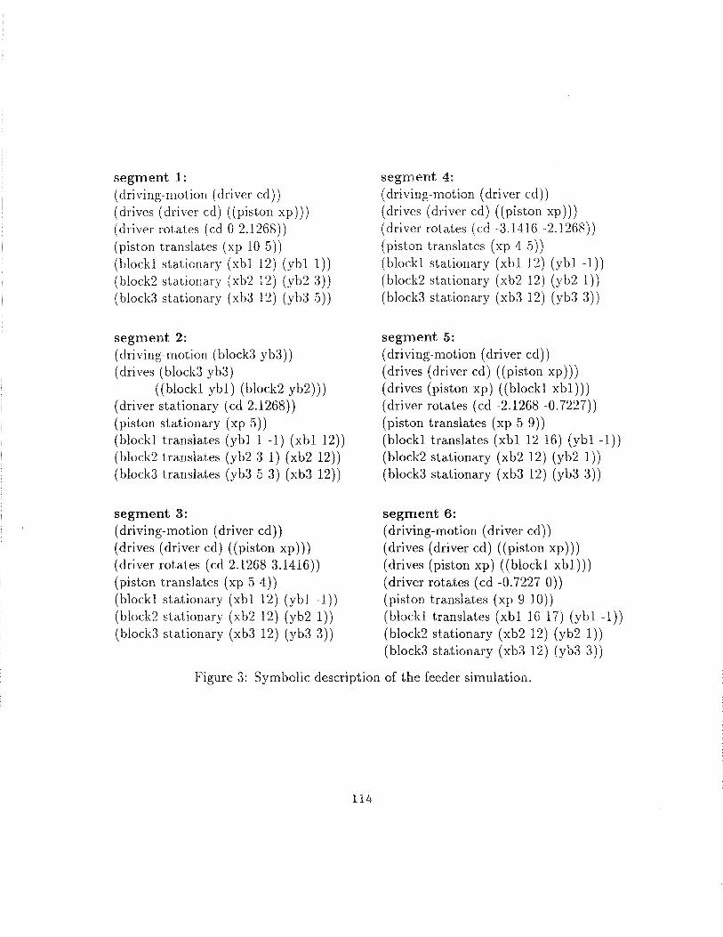
Figure 3: Symbolic description of the feeder simulation.
114
The fixed parts form the frame, the fixed-axesparts form fixed-axessubassemblies,and the linkage parts along with the connectedfixed-axesparts form linkages. In
the feeder,the driver mounting, magazine,and processingtable form the frame, thedriver, link, pins, andpistonform a linkage,andthe frame, driver, piston,andblocksform a fixed-axessubassembly.
The modelingmodule finds the axesof motion of the fixed-axesparts,decomposesthe fixed-axessubassembliesinto pairsof interactingparts,andfinds their degreesoffreedom. For example,it finds that the magazineallows the blocks to move up anddown,but preventsthemfrom moving left andright or from rotating. The subassem-bly analysismoduleconstructsthe regiondiagramsof the linkagesandthe interactingpairs. For example, it determinesthat rotating the driver slides the piston left andright, andthat the piston supportsthe bottom block in the initial configuration.
The simulatorderivesthe CS path that the mechanismtraverses.Figure2 showsoneconfiguration from eachof thefirst six segmentsin the path,which representthefirst cycleof thefeeder. Segment1 lies in the initial region. The contactbetweenthepiston and the bottom of block 1 preventsthe blocks from dropping. The programconstructsa path segmentin which the driver rotates, the link moves, the pistonretracts,andthe other partsdo not move. The segmentendswhen the piston movesout from under block 1, causinga contactchange. In segment2, gravity causestheblocks to drop onto the table. In segment3, the driver movesthe piston left. Insegment4, the driver movesthe piston right until it touchesblock 1. In segment5,the contactbetweenthe piston andthe sideof block 1 enablesthepiston to push theblock to the right. In segment6, block 1 breakscontactwith block 2 andcontinuesright. The cycle repeatsuntil the magazineempties.
Figure 3 shows the symbolic descriptionsof the six segmentsof the CS path.Each descriptionspecifiesthe driving motion, how the driving motion propagates,and how the parts move. The motion description of a part specifiesit name, itsmotion type, andthe initial and final values of its mobilecoordinates. The motiontypes are stationary, translates,and rotates. In segment 1, the Cd coordinateof thedriver drives the ~ coordinate of the piston. The driver rotates from Cd = 0 toCd = 2.1268,the piston translatesfrom x~= 10 to x~= 5, and so on.
3 Implementation
Figure 4 showsthe programorganization.We focus on the simulationmodule in thispaper, leaving the other modulesto our longer paper [7]. The inputs are the region
diagramsof thelinkagesandthefixed-axespairs, theinitial configuration,the internalforces,a sequenceof input motions, and a time allotment, The output is a symbolicdescription of the motion path, a region diagram, and a sequenceof closely spaced
configurations, which the animationmodule outputsto a graphicsworkstation.A motion is specified as a coordinate,a velocity, anda samplingrate. The path
generatedby a motion (x, v, .s) within a region is constrainedby the part contacts
115

Input: mechanismstructure,initial configuration, input motions,and time allotment
1. modeling
2. subassemblyanalysis
3. kinematic simulation with simpledynamics
(a) apply internal motions
(b) apply next input motion
(c) if blocked, switch to next input motion
(d) if time and input motions remain, go to step (a)
4. animation
Output: CS path, animation, and region diagram
Figure 4: Kinematic simulation with simpledynamics.
within the region, which are representedas equalitiesand inequalitiesamongthepart coordinates. The motion explicitly specifiesx as a linear function of time x(t) =
xo + vi. The constraints determinecertain coordinatesas functions of x, henceof I.
If thesecoordinates include the input of a linkage, then the linkage determinesits
other coordinatesas a function of x. (The programhandlesone degreeof freedom,
nonredundantlinkages.) The constraints may then determineadditional coordinatesas functions of the linkage output, henceas functions of x, and so on. The motionleavesthe other coordinatesconstant. It ends at the maximumI that satisfiestheconstraints,at which timesomeparametercrossesthe regionboundary. The programtraces the CS path by augmentingthe region constraintswith the constraint x =
xo + vi, calculating tmax, solving the constraints for the coordinates as functions
of I then substituting the values 0, s,2s,. . . , tmax for t. The program derives the
symbolic descriptionof the path segmentfrom the input motion and the coordinate
dependencies.In segment1 of the feederanimation (Figure 3), the input motion (Cd, 1, 1/4)
drives the mechanism.The linkage determinesthe linkagecoordinates,including theoutput x~,as functions of Cd. The constraintsdetermineno further coordinatesasfunctions of x~. The program sets Xb~and y~,j (i = 1,2,3) to their initial values,indicating that the piston does not move the blocks. In segment 2, gravity drivesthe mechanism,taking precedenceover the driver. The constraintsdeterminethe ycoordinatesof the blocks and leave the other parts fixed. In segment5, the driver
drives the mechanism.The regionconstraintsdeterminex51 as afunction of x~,hence
of Cd, becauseof the contactconstraintbetweenblock 1 and the piston.
The programincrementallygeneratesthe regions that the motion path enters. Itstarts with an empty region diagram. It retrieves the regionsin the current diagram
116
and returns those that contain the current configuration. A configuration lies ina region if it satisfies the constraintsthat define the region. If no current regioncontainsthe configuration, the programconstructsthe containingregions,addsthemto the region diagram,andreturnsthem. It maintainsthe regionsin ahashtableforessentiallylinear time access.
Given an input configuration outside the current region diagram,the programconstructsthe containingregionsby composingthe constraintsimposedby the fixed-axessubassemblyand by the linkages. It retrievesthecontainingregionsin the regiondiagramof eachpair of fixed-axesparts. This processnormally yields oneregion perdiagram,but yields two regionsin diagramswherethe configuration lies on a regionboundary. Eachchoiceof onecontainingregion per pairwisediagramdefinesapoten-tial region in the fixed-axessubassemblydiagram. Intersectingthe componentsof apotential regionyields the collectivekinematicconstraintsimposedby the fixed-axesparts. The potential region definesan actual region if the intersectionis nonempty.
After findingor constructingthefixed-axesregionfor aconfiguration, theprogramcomposesit with the linkage region diagrams. Eachlinkage propagatesconstraintsbetweenits input andoutput coordinates.Supposethat a linkage hasinput x, outputy, and input/output function y = f(s) andthat the fixed-axesconstraintsrestrictx and y to intervals [xe, 5,,] and [yi, Yu]. The linkage further restricts y to the setf([xi,x,1]) and x to the set f’([yi,y~]). The program calculatesthe linkage con-straintsfrom the linkageregiondiagram,which encodesthe input/output function ina table.
The programusesasubsetof the BOUNDERinequality prover [8] to reasonaboutthe linear inequality constraintsthat define the contact regions of the fixed-axessubassembly.It usesthe constraintmanagerfor threetasks: (1) to test if apotentialregion definesan actual region, that is if the constraintsin the potentialregion havea solution; (2) to derive the bounds on a variable implied by a constraint set; and (3)to test if the contactswithin a region determinea coordinatey as a function of x,that is if the upper and lower boundsof y in termsof x coincide.
4 Evaluation
The feederexampleshowsthat kinematicsimulation with simple dynamicsvividlyandefficiently capturestheworkingsof a realisticmechanism.The programgeneratesa CS path containing 90 configurationsand aregion diagramcontaining 16 regions.It runs in 10 minuteson aDEC workstationandanimatestheresulting 90 snapshotsin real time on an IRIS workstation. The programconstructs9 region diagramsforpairs of fixed-axesparts: 3 block/blockdiagramswith 6 regionsapiece,3 piston/blockdiagramswith 6 regionsapiece,and3 block/framediagramswith 2 regionsapiece. It
constructsa single linkage region diagramcontaining301 configurations. Thesepair-wise regionsyield 373,248potential regionsfor the overall mechanism.The programexamines48 of thesepotential regions (0.01%) in tracing the CS path, whereasour
117
previousprogramexamines2115potential regions(0.5%) in constructingthe full 217region diagram. Thus,simulating the feederis 50 timesless work thanconstructingits full region diagram.
Wehavetestedour program on a dozenrealistic examples,including the feeder,a transmission,a rim lock, and a shoe brake. Each exampleillustrates differentaspectsof kinematicsimulationwith simpledynamics.The feederhasmanymovingparts, containsa linkage, andusesgravity. The transmissionhascomplexpart shapesand interactions. The rim lock hasmany regionsin its region diagramandcontainsa spring that opposesthe input motion. The shoe brake has simultaneousinputmotions, springs, and friction. They all have varying contacts,multiple operatingregions, high-dimensionalCSs,andmultiple degreesof freedom. All simulationsrunin under 10 minutesandexplorea very small fraction of the CS.
We surveyedover 2500mechanismsin Artobolevsky’sfour-volumeMechanismsinModernEngineeringDesign [1] to determinethe percentageof practicalmechanismscoveredby kinematic simulation with simple dynamics amid to identify significantexceptions. We found that 59% of the mechanismsare feasible mechanisms,that79% arecoveredby simple dynamics,andthat 48% are both feasibleandcoveredbysimpledynamics.The details appearin our longer paper [7].
We examinedthe accompanyingtext descriptionsto determineif simpledynamicscapturesthe workings of the mechanism.The descriptionsfocus on the aspectsofthe mechanismsrelevantto their function andabstractawayother aspects.We deemthat simple dynamicscoversa mechanismif it matchesthe text descriptionof theforces and frictions. For example,the text describesthe workings of the feederasfollows. (We havechangedthe part namesto ours for clarity.)
Workpiecesdrop from the magazineonto the processingtable. A mecha-nism which is not shown periodically rotatesthe driver throughonecom-pleterevolution,beginning from its extremeleft-handposition. Rotatingabout a fixed axis, the driver, by meansof the connectinglink, recip-rocates the piston which ejects the bottom workpieceinto a chute notshown. When the driver returns to its extremeleft-hand position, thenext workpiecedropsonto the processingtable (Vol 2. p. 592).
This descriptioncapturesthe function of the feederwithout specifyingthe rate atwhich the blocks drop, the effect of friction, or the transientaccelerations.It showsthat the simulationin Figure2 and its symbolicdescriptionin Figure3 appropriatelycapturethe workings of thefeeder.
5 Conclusion
This paper presents a practical simulationprogramfor rigid part mechanisms.Thesimulation captures the kinematic constraints imposed by part contacts and input
118

motions along with the dynamicalconstraintsimposedby gravity, springs,andfric-tion. The program representsthe kinematicsas a partition of the mechanismCSinto regionsof uniform motion. It generatesthe simulation by tracing the CS paththat the mechanismtraversesunder the input motions anddynamicalconstraints.It
producesasymbolicdescriptionanda three-dimensionalanimationof thesimulation.Our simulation algorithm is limited by the types of mechanismsit can analyze
andby the dynamicalphenomenait can model. In apreviouspaper [6], we describemethodsfor extendingthe kinematiccoveragefrom 59% to about90% while maintain-ing reasonableprogram complexity and computationalefficiency. Theseextensionswould raisethe overallcoveragefrom 48% to about72%, sincesimpledynamicscovers80% of the mechanisms.Extensionsto simpledynamicsincludeimproving modeling,steady-statedynamics,and full dynamicalsimulation. Improving modeling investsincreasedmodelingeffort for easeof analysis. An exampleis replacing2D springsby 1D springswherepossible. Steady-stateanalysisabstractsaway transientaccel-eration and vibration, but derives the precisesteady-stateeffect of forces, masses,momentsof inertia, andfriction. It sufficesfor friction mechanisms,mechanismswithcompetingforces or inertia such as governorsandtripping mechanisms,and brakes.Full dynamicalanalysisis necessaryfor correctly simulatingmechanismsnot coveredby simple dynamicsand for accuratelysimulating coveredmechanisms.An exam-ple of such mechanismis a clock escapement,since the precisetransient behaviordeterminesthe exact interval betweenclock ticks.
Kinematicsimulationswith simpledynamicssetsthe stagefor full dynamicaianal-ysis. Modeling identifies the relevant CS coordinatesand possiblepart interactions.We can formulatethe full dynamicalequationsin CS coordinatesinstead of in partcoordinates,reducingby a factor of six thenumberof equationsandmaking themlessstiff. Subassemblyanalysisandsimulationcomputepart interactionsandcoordinatedependencies.We neednot test for part collisions at eachintegration stepbecausethe regiondiagramspecifiesthe configurationswherepartscollide. The simulatorcanfind the initial region, integratethe equationswithin the region bounds,thenshiftto the next region. This procedureshouldcombinethe robustnessandefficiency ofkinematicsimulation with the accuracyof traditional simulation.
We believeour researchservesthe larger goalof automatingmany aspectsof me-chanical engineering,including design, validation, and cataloging. Engineersworkwith concisedescriptionsof mechanismsthat specifyonly the informationrelevanttotheintendedbehavior. A typical descriptionconsistsof ablueprintof the mechanismgeometryandof an English explanationof the relevantdynamics. Engineeringpro-gramsshould generateand understandthesedescriptionsin order to communicatewith usersand with engineeringdatabases.We demonstratethat the symbolicout-put of our programmatchesthesedescriptionsfor a large classof mechanisms.Wehypothesize that the descriptions set the stage for more detailed analysis and provideacomputationalbasisfor otherengineeringtasks,suchas designingmechanismsthatachievespecifiedfunctions.
119
References
[1] Artobolevsky, I. Mechanismsin Modern EngineeringDesign,volume 1-4. (MIRPublishers, Moscow, 1979). English translation.
[2] Cremer, J. An architecture for general purpose physical system simulation—
integratinggeometry,dynamics,and control. TechnicalReport 89-987, CornellUniversity, Apr. 1989.
[3] Gelsey,A. Automated physical modeling, in: Proceedingsof the EleventhInter-national Joint Conferenceon Artificial Intelligence, 1989.
[4] Haugh, E. (Ed.). Computer Aided Analysis and Optimization of Mechanical
SystemDynamics. (Springer-Verlag,1984).
[5] C. A. Kramer, Solving geometricconstraint systems.in: Proceedingsof the 8thNational Conferenceon Artificial Intelligence, Boston (1990) 708—714.
[6] Joskowicz, L. and Sacks, E. P. Computational kinematics. Artificial Intelli-
gence 51 (1991) 381—416.
[7] Sacks, E. P., and Joskowicz, L. Mechanism Simulation using ConfigurationSpacesand SimpleDynamics.TechnicalReport,March 1992.
[8] Sacks, E. P. Hierarchical reasoning about inequalities, in: Proceedingsof the
National Conferenceon Artificial Intelligence,1987.
120
Appendix: more examples
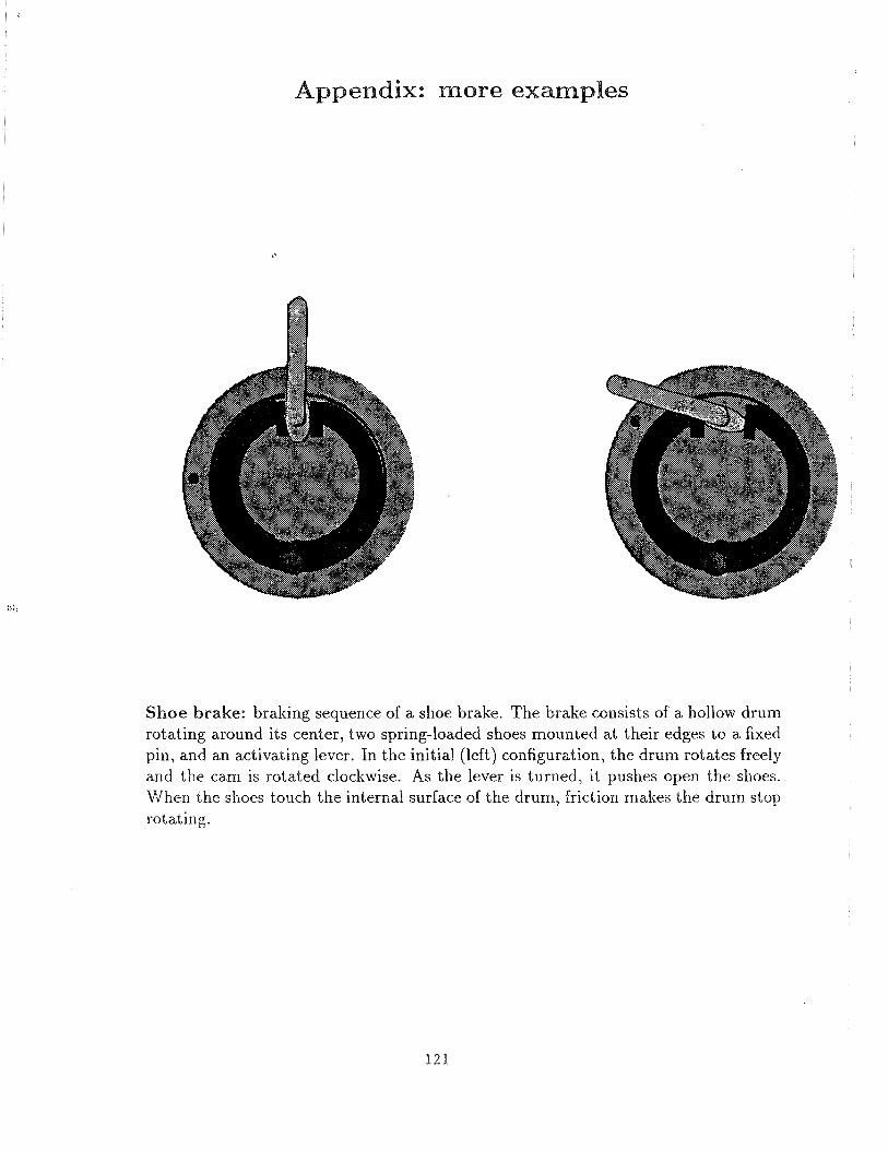
Shoebrake: brakingsequenceof ashoebrake. The brakeconsistsof a hollow drumrotating aroundits center,two spring-loadedshoesmountedat their edgesto a fixedpin, andan activatinglever. In the initial (left) configuration, the drum rotatesfreelyandthe cam is rotatedclockwise. As the lever is turned, it pushesopen the shoes.When the shoes touch the internal surface of the drum, friction makes the drum stop
rotating.
121
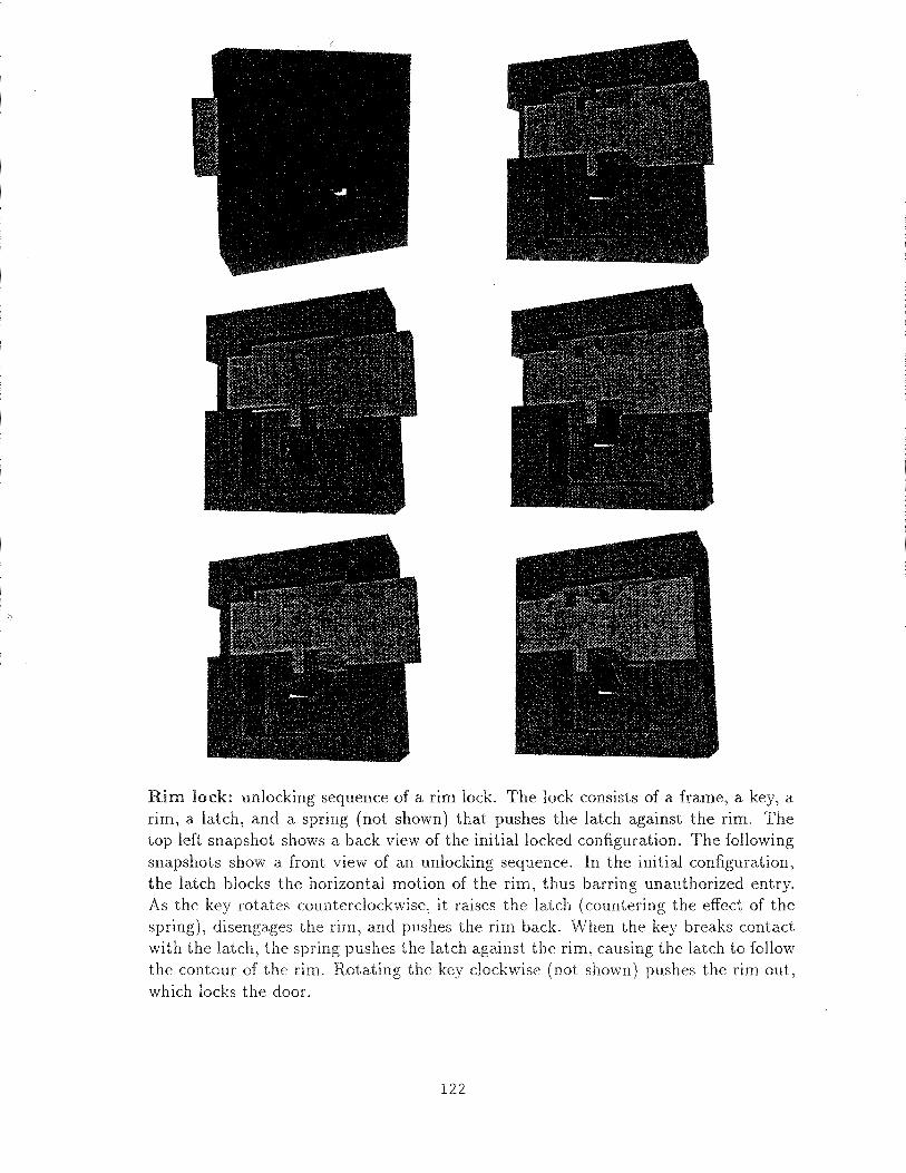
Rim lock: unlocking sequenceof a rim lock. The lock consistsof a frame, a key, arim, a latch, and a spring (not shown) that pushesthe latch against the rim. Thetop left snapshotshowsaback view of the initial locked configuration. The followingsnapshotsshow a front view of an unlocking sequence.In the initial configuration,
the latch blocks the horizontal motion of the rim, thus barring unauthorizedentry.As the key rotatescounterclockwise,it raises the latch (counteringthe effect of thespring), disengagesthe rim, andpushesthe rim back. When the key breakscontactwith the latch, the spring pushesthe latch againstthe rim, causingthe latch to follow
the contourof the rim. Rotating the key clockwise(not shown) pushesthe rim out,which locks the door.
122
feeder transmission rim lock shoebrake
movingpartspart faceslinkagesCS dimension
877
117
844609
38004
46004
dynamicsinput motions
gravity1
none1
spring1
friction andsprings2
mechanismDOFpotential regionsexploredregionsnonemptyregionstraversedregions
4373,248
211521748
231,360,000
49132
423523377922
2
6416161
quadranglessnapshotsruntime (secs.)
116888487
3626322
2178749
8350
612
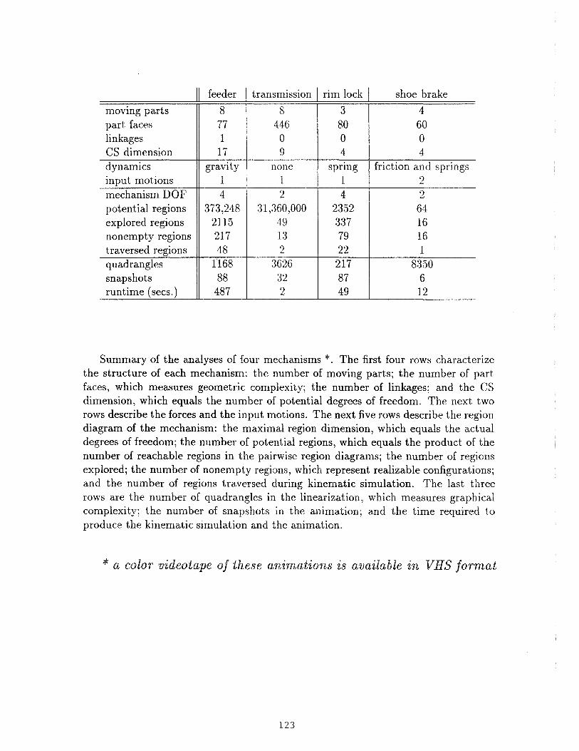
Summaryof the analysesof four mechanisms‘~. The first four rows characterizethe structure of each mechanism: the number of moving parts; the number of partfaces, which measuresgeometriccomplexity; the numberof linkages; and the CSdimension, which equals the number of potential degreesof freedom, The next tworows describethe forces and the input motions. The next five rows describethe regiondiagram of the mechanism: the maximal region dimension, which equals the actualdegreesof freedom; the number of potential regions,which equals the product of thenumberof reachableregions in the pairwiseregion diagrams;the numberof regionsexplored; the number of nonempty regions, which represent realizable configurations;and the number of regions traversed during kinematic simulation. The last threerows are the numberof quadranglesin the linearization,which measuresgraphicalcomplexity; the number of snapshotsin the animation; and the time required toproducethe kinematicsimulation andthe animation.
* a color videotapeof theseanimationsis available in VHSformat
123


![[Scotoss]crisis simulation program service](https://img.pdfslide.net/doc/110x75/58ed1ec41a28ab591f8b4643/scotosscrisis-simulation-program-service.jpg)