Embed Size (px)
Citation preview

Modeling and Kinetics:Forces and Moments of Force*
*Some of the materials used in this lecture are derived from:
1. Winter, D. A. (1990). Biomechanics and motor control of human movement (2nd ed.). New York: John Wiley & Sons.
2. Brown, E. W. , & Abani, K. (1985). Kinematics and kinetics of the dead lift in adolescent power lifters. Medicine and Science in Sports and Exercise, 17 (5)554-566.

Lecture Topics
1. Bone-on-bone vs joint reaction forces
2. Kinetic link-segment model and calculations
3. Force platform
4. Interpretation of moment of force curves

1. Bone-On-Bone vs. Joint Reaction Force
• Bone-on-bone forces– Actual forces experienced at the articulating surfaces– Include the effect of muscle contraction (e.g.,
compressive, possibly shear and torsional forces)
• Joint reaction forces– Forces experienced between segments in a free body
diagram

Bone-On-Bone vs. Joint Reaction Force
• Case 1– Weight of suspended
shank and foot = 100 N
– 50 N of force transmitted to each of 2 muscles
– Bone-on-bone force = 0 N
– Joint reaction force = 100 N

Bone-On-Bone vs. Joint Reaction Force
• Case 2– Weight of
suspended shank and foot = 100 N
– Each of 2 muscles contraction at 85 N
– Bone-on-bone force = 70 N
– Joint reaction force = 100 N

2. Kinetic Link-Segment Model and Calculations

Because we cannot typically measure internal forces and torques in a biological
system directly, we depend on indirect measurement of these parameters using
kinematic and anthropometric data.
• Force = Mass X Acceleration
F = MA
• Torque or Moment = Moment of Inertia X Angular Acceleration
T or M = I

If we have a full kinematic description, accurate anthropometric measures, and
external forces; we can calculate the joint reaction forces and the net muscle moments.
Inverse Solution
insight into the net summation of all muscle activity at each joint

The validity of any assessment is only as good as the model itself!!!
Requirements: accurate measures of1. segment masses2. centers of mass3. joint centers4. moments of inertia

Relationship among Kinematic, Kinetic, and Anthropometric Data and the Calculated Forces, Moments, Energies, and
Power Using an Inverse Solution and a Link-segment Model

Assumptions in Using a Link-segment Model
• each segment has a fixed mass located as a point mass at its center of mass
• joint centers are considered to be hinged or ball and socket joints
• mass moment of inertia of each segment about its mass center (or either proximal or distal joints) is constant during the movement
• length of each segment remains constant during the movement

Equivalence between Anatomical and Link-segment Model of the Lower Extremity
M1, M2, and M3, considered to be concentrated at points (center of mass of each segment)
length of each segment and length from proximal and distal joints to segment center of mass considered to be fixed
moments of inertia I1, I2, and I3 about each center of mass considered to be fixed

Forces Acting on aLink-segment Model
• Gravitational Forces• Ground Reaction and/or
External Forces• Muscle and Ligament Forces
Where do we obtain the data for the various parameters?

Steps in Solving Kinetic Link-Segment Problems
1. Draw free body diagram including forces (joint reaction, weight, ground reaction, other external), net muscle moments, important coordinates (e.g., center of mass of segments, ends of segments, center of pressure), segment orientation, and linear and angular acceleration
Can you draw a free body diagram?

Steps in Solving Kinetic Link-Segment Problems
1. Draw free body diagram including forces (joint reaction, weight, ground reaction, other external), net muscle moments, important coordinates (e.g., center of mass of segments, ends of segments, center of pressure), segment orientation, and linear and angular acceleration

2. Write all knowns:- Subject mass
- Subject height
- Segment proportion of subject height
- Segment proportion of mass
- Segment orientation
- Segment radius of gyration/segment length
- Linear and angular accelerations
- Joint reaction forces
- Ground reaction and other external forces
- Net muscle moments
- Center of pressure
- Etc.

3. Write all unknowns that must be solved:a. Joint reaction forces
b. Net muscle moments
c. Others
4. Decide an order to the solution process:a. Usually distal segments first (distal to
proximal)
b. Usually reaction forces solved first
c. Usually net muscle moments solved after reaction forces
5. Solve problems
6. Determine if results make sense
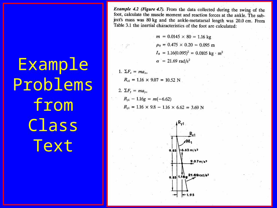
Example Problems
from Class Text

Example Problem from Class Text (continued)

Example Problem from Class Text (continued)

Continued

Example of Research Models
Brown, E. W. , & Abani, K. (1985). Kinematics and kinetics of the dead lift in adolescent power lifters. Medicine and Science in Sports and Exercise, 17 (5)554-566.

What is a kinematic model?

Kinematic Model
describes the linear and angular position and motion of segments

Example of a 2 Dimensional Single Segment Kinematic Model and Equations:

Two Dimensional Human Model
What is the purpose of defining events?

What is a kinetic model?

Kinetic Model
takes into consideration forces and torques associated with linear and
angular acceleration

Example of a2 Dimensional Multiple Segment Kinematic and Kinetic Model

What is nomenclature?

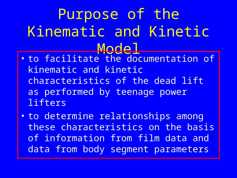
Purpose of the Kinematic and Kinetic Model
• to facilitate the documentation of kinematic and kinetic characteristics of the dead lift as performed by teenage power lifters
• to determine relationships among these characteristics on the basis of information from film data and data from body segment parameters

Example of a2 Dimensional Multiple Segment Kinematic and Kinetic Model -Close Up View of Segments:

Example of a2 Dimensional Multiple Segment Kinematic and Kinetic Model -Close Up View of Segments:

Example of a2 Dimensional Multiple Segment Kinematic and Kinetic Model -Close Up View of Segments:

Example of a2 Dimensional Multiple Segment Kinematic and Kinetic Model -Close Up View of Segments:

Example of a2 Dimensional Multiple Segment Kinematic and Kinetic Model -Close Up View of Segments:

Example of a2 Dimensional Multiple Segment Kinematic and Kinetic Model -Close Up View of Segments:

Equations for calculating
accelerations:

Equations for calculating
forces:

Equations for calculating moments:

What are the assumptions used in this research model?

Assumptions Associated with Multiple Segment Kinematic and Kinetic Model
• Lifter and bar system are bilaterally symmetrical in the sagittal plane (2 dimensional).
• Body segments could be treated as rigid bars.
• Dempster’s data could be used to represent the segment mass proportions and centers of gravity locations in the population.
• Joints, which link the segments together, could be treated as a frictionless and pinned.

Assumptions Associated with Multiple Segment Kinematic and Kinetic Model• The segment connecting the center of the
shoulder joint and the center of the neck at the level of the seventh cervical vertebrae could be treated as a “massless” segment with defined length which transmits force and torque.
• The location of the center of gravity of the hand could be treated as coincident with the center of the bar, and no torque was applied to the bar by the hands.
• Acceleration of the ankle joint was equal to zero throughout the entire lift.

What happens if we change from a dynamic to a static model?

Static Versus Dynamic Model• Static Model
– Considers positions of segments
– Does not consider linear and angular accelerations to move from one position to another
– Assumes that linear an angular acceleration are equal to zero
– Assumes forces and torques associated with acceleration are equal to zero
• Dynamic Model– Considers positions of
segments
– Takes linear and angular accelerations into account
– Assumes that linear and angular accelerations may not be equal to zero
– Forces and torques associated with acceleration may not equal to zero
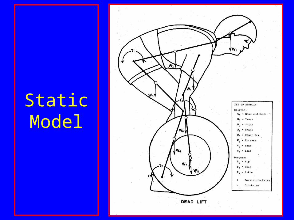
Static Model

How do the equations change when changing from a dynamic to
a static model?


3. Force Platform
What is a force platform and how is it used in biomechanics?

Force Platform (continued)
• Metal platform in which force transducers (e.g., strain gauge, capacitive, piezoelectric, piezoresistive) are embedded
• Force transducers change electrical resistance in proportion to load applied
• Used to measure common three dimensional force (ground reaction force) and moments acting on the body

Force Platform (continued)• Types
– Metal plate supported by 4 triaxial transducers (see figure)
– Metal plate mounted on central pillar (see figure)

Force Platform (continued)
What is the center of pressure and how is it used?

Force Platform (continued)• Center of Pressure
(COP)– Displacement
measure indicating the path of the resultant ground reaction force vector on the force platform
• A – heel to toe footfall pattern runner
• B – mid-foot foot strike pattern runner

Force Platform (continued)• Center of Pressure (COP)
– Equal to the weighted average of the points of application of all downward acting forces on the force platform

Force Platform (continued)
• Center of Pressure (COP)– Used in conjunction with kinematic information
about the body part (e.g., foot) in contact with the force platform

Force Platform (continued)• Center of
Pressure Calculation
FFFFF
y
zxzxXx 00001
2
FFFFF
y
xxzzZz 00001
2

Force Platform (continued)• Problem
Fy =200N
F00 = 50N
Fx0 = 50N
Fxz = 50N
F0z = 50N
X= 100cm
Z= 100cm
Guess cop location?
FFFFF
y
zxzxXx 00001
2
FFFFF
y
xxzzZz 00001
2

FFFFF
y
zxzxXx 00001
2
cmx
N
NNNNx
50
200
505050501
2
100
FFFFF
y
xxzzZz 00001
2
cmz
N
NNNNz
50
200
505050501
2
100

Force Platform (continued)• Problem
Fy =200N
F00 = 100N
Fx0 = 50N
Fxz = 25N
F0z = 25N
X= 100cm
Z= 100cm
Guess cop location?
FFFFF
y
zxzxXx 00001
2
FFFFF
y
xxzzZz 00001
2

FFFFF
y
zxzxXx 00001
2
cmx
N
NNNNx
5.37
200
2510025501
2
100
FFFFF
y
xxzzZz 00001
2
cmz
N
NNNNz
25
200
5010025251
2
100

Force Platform (continued)
• Fy interpretation?

Force Platform (continued)
• Fy
– First peak – mass accelerated upward
– Second peak – push off
– Valley – unloading during knee flexion

Force Platform (continued)
• Mz interpretation?
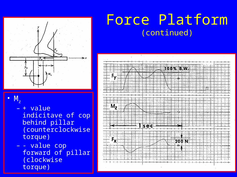
Force Platform (continued)
• Mz
– + value indicitave of cop behind pillar (counterclockwise torque)
– - value cop forward of pillar (clockwise torque)

Force Platform (continued)
• Fx interpretation?

Force Platform (continued)
• Fx
– First peak; - force, push back against foot
– Second peak; push off of foot

4. Interpretation of Moment of Force Curves