Embed Size (px)
Citation preview
Modeling and Simulation of Used Nuclear Fuel During Transportation with Consideration of Hydride Effects and Cyclic Fatigue

Disclaimer This information was prepared as an account of work sponsored by an agency of the U.S. Government. Neither the U.S.. government nor any agency thereof, nor any of their employees, makes any warranty, expressed or implied, or assumes any legal liability or responsibility for the accuracy, completeness, or usefulness, of any information, apparatus, product, or process disclosed, or represents that its use would not infringe privately owned rights. References herein to any specific commercial product, process, or service by trade name, trade mark, manufacturer, or otherwise, does not necessarily constitute or imply its endorsement, recommendation, or favoring by the U.S. Government or any agency thereof. The views and opinions of authors expressed herein do not necessarily state or reflect those of the U.S. government or any agency thereof.
FCRD-UFD-2015-000273 INL/EXT-15-36697
Modeling and Simulation of Used Nuclear Fuel During Transportation with Consideration of Hydride Effects
and Cyclic Fatigue
Pritam Chakraborty, Idaho National Laboratory Piyush Sabharwall, Idaho National Laboratory
Kadir Sener, STANEX Amit H. Varma, STANEX
Robert E. Spears, Idaho National Laboratory Justin Coleman, Idaho National Laboratory
Revision 0 September 30, 2015
Idaho National Laboratory Idaho Falls, Idaho 83415
http://www.inl.gov
Prepared for the U.S. Department of Energy
Office of Used Nuclear Fuel Disposition Research and Development Under DOE Idaho Operations Office Contract DE-AC07-05ID14517

This page intentionally left blank.
Modeling and Simulation of Used Nuclear Fuel Transportation and Effect of Hydrides on High Cycle Fatigue
September 2015 v
SUMMARY This report fulfills the M3 milestone, M3FT-15IN08020112 Analyses of Variables in UNF Transportation, under Work Package Number FT-15IN080201.
Operational experience and ongoing Research and Development (R&D) in light water reactor fuels have been used to support higher burnup fuel capacities. An increase in fuel burnup can lead to changes in fuel material properties and material states. Important aspects of high burnup fuel that may cause changes in material properties and material states are: higher decay heat, changes in cladding thickness, higher hydrogen content in the cladding with increase in production of the fission gas, and hydride effect.
The high burnup used nuclear fuel (UNF) currently stored by utilities at nuclear power plant sites will be transported to interim and long-term storage facilities. The basis for transportation of high burn-up UNF has not been developed. If retrievability of UNF is important and cladding is the barrier than it is important to demonstrate that there is a high confidence in low probability of failure (HCLPF) of high-burnup in UNF cladding during transportation and extended storage. This will ensure retrieveability, if necessary, and maintain fuel cladding as the containment barrier during normal conditions of transportation (NCT). Establishing HCLPF of fuel cladding during transportation and extended storage will require a combination of numerical modeling and simulation and experimental tests.
The objective of this work is to understand the integrity of UNF during transportation. Previous analysis work has been performed to look at the integrity of UNF during transportation but these analyses have neglected to analyze the effect of hydrides and flaws (fracture mechanics models to capture radial cracking in the cladding).
In this study, the clad regions of interest are near the pellet-pellet interfaces. These regions can experience more complex stress-states than the rest of the clad during cooling and have a greater possibility to develop radially reoriented hydrides during vacuum drying.
Contrary to the expected behavior, the geometry without the chamfer resulted in an increased damage due to circumferential stresses than the chamfered geometry. Hence, the presence of geometric discontinuities like chamfer may not be the dominant factor controlling fatigue damage, however this indicates inclusion of individual pellets is very important. More detailed information on the state of fuel-pellet system before transportation can further improve this study, along with adapting lower length scale models with local plasticity and fatigue crack growth to improve fatigue damage prediction.
From the analysis presented in Section 3 the estimated cumulative damage and number of cycles to failure of high burn-up used fuel using finite element analysis method was determined. This section of the report also presents the review of experimental and numerical research programs conducted on mechanical performance of high burnup UNF under normal transport. The results and findings of previous researchers were corroborated and expanded to be used for considering damage parameters in modeling (the damage simulates the effect
Modeling and Simulation of Used Nuclear Fuel Transportation and Effect of Hydrides on High Cycle Fatigue
vi September 2015
of localized cracks at the PPC interface, cracks likely caused by hydride reorientation).
The damage model results indicated that most of the damage was caused by the large amplitude cycles, with the largest two amplitudes being responsible for more than 90% of the cumulative damage,
The cumulative damage was influenced by the damage parameters (the damage slope level) used in the models,
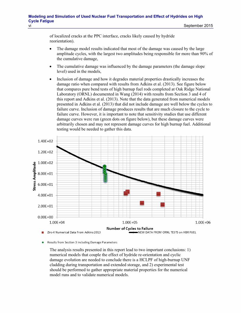
Inclusion of damage and how it degrades material properties drastically increases the damage ratio when compared with results from Adkins et al. (2013). See figure below that compares pure bend tests of high burnup fuel rods completed at Oak Ridge National Laboratory (ORNL) documented in Wang (2014) with results from Section 3 and 4 of this report and Adkins et al. (2013). Note that the data generated from numerical models presented in Adkins et al. (2013) that did not include damage are well below the cycles to failure curve. Inclusion of damage produces results that are much closure to the cycle to failure curve. However, it is important to note that sensitivity studies that use different damage curves were run (green dots on figure below), but these damage curves were arbitrarily chosen and may not represent damage curves for high burnup fuel. Additional testing would be needed to gather this data.
The analysis results presented in this report lead to two important conclusions: 1) numerical models that couple the effect of hydride re-orientation and cyclic damage evolution are needed to conclude there is a HCLPF of high-burnup UNF cladding during transportation and extended storage, and 2) experimental test should be performed to gather appropriate material properties for the numerical model runs and to validate numerical models.
Modeling and Simulation of Used Nuclear Fuel Transportation and Effect of Hydrides on High Cycle Fatigue
September 2015 vii
CONTENTS
SUMMARY .................................................................................................................................................. v
1. INTRODUCTION .............................................................................................................................. 1
2. SUBMODELING APPROACH ......................................................................................................... 2
2.1 Fuel-Assembly Level Model .................................................................................................... 3
2.2 Two-Pellet Model .................................................................................................................... 6
2.3 Multi-Axial Fatigue Damage Model ........................................................................................ 9
2.4 Results and Discussion ........................................................................................................... 10
2.5 Effect of Hydride on Fatigue Damage ................................................................................... 10
2.6 Effect of Pellet-Pellet Interaction on Fatigue Damage ........................................................... 12
2.7 Fatigue Damage in Different Regions in the Fuel Assembly from Submodel Analyses ................................................................................................................................. 13 2.7.1 Region B ................................................................................................................... 14 2.7.2 Regions A and C ....................................................................................................... 15
2.8 Effect of Chamfer on Fatigue Damage .................................................................................. 16
3. Consideration of Cyclic Damage and Fatigue on UNF Cladding .................................................... 19
3.1 Background ............................................................................................................................ 19 3.1.1 Used Nuclear Fuel Loading and Structural Performance under Normal
Conditions of Transport - Demonstration of Approach and Results of Used Fuel Performance Characterization by Adkins et al. [2] ........................................... 19
3.1.2 CIRFT Testing Results on High Burnup UNF by Wang et al. [5] ............................ 20 3.1.3 Buckling Behavior of Spent Nuclear Fuel Rods by Ramasamy et al.[9] .................. 24
4. BEHAVIOR AND ANALYSIS OF UNF UNDER DYNAMIC LOADING .................................. 25
4.1 UNF Model without Damage Material Properties ................................................................. 25 4.1.1 Loading and Boundary Conditions ........................................................................... 25 4.1.2 Analysis Results and Damage Evaluation................................................................. 28
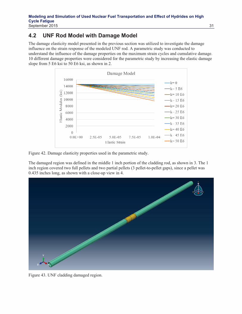
4.2 UNF Rod Model with Damage Model ................................................................................... 31
5. CONCLUSION ................................................................................................................................ 35
6. REFERENCES ................................................................................................................................. 36
FIGURES Figure 1. Schematic of the submodeling approach pursued in this work to evaluate hydride effect
on fatigue life. The red-circles denote regions considered for submodeling. The rail car, basket and fuel-assembly images are taken from Adkins et al.’s report [2]. ................................ 3
Figure 2. Hydride reorientation in PWR zircaloy-4 cladding at burnup of 48 GWd/t [6]. (a) As irradiated. Reorientation at different cooling rates and circumferential stress (b) 30°C/h and 115 MPa, (c) 3°C/h and 115 MPa. ......................................................................................... 3
Modeling and Simulation of Used Nuclear Fuel Transportation and Effect of Hydrides on High Cycle Fatigue
viii September 2015
Figure 3. Locations of beam elements in the assembly model considered for submodel analysis: (a) Axial; (b) X-Y plane. .............................................................................................................. 4
Figure 4. Displacement and rotation histories for the two pellet-clad models obtained at one of the locations from the assembly level model. The figures show the difference of displacement and rotation components between the 2 nodes (left and right) of the beam element representing the two pellet-clad models. (a) x-translation; (b) y-translation; (c) z-translation; (d) x-axis rotation; (e) y-axis rotation; (f) z-axis rotation. ...................................... 5
Figure 5. Schematic of the two pellet-clad submodels. ................................................................................ 6
Figure 6. (a) Rectangular geometry (1 × 1 × 10 mm) to verify rotational and translation boundary conditions obtained from fuel assembly model. (b) Translations along X and Y-axis. (c) Translations along X and Z-axis. .................................................................................................. 6
Figure 7. (a) Rotation of 5 degrees around Z-axis. (b) Rotation of 5 degrees along X-axis. ........................ 7
Figure 8. (a) Two pellet-clad model. (b) Deformation (magnified by 2) for x-y-z translations of 0.01 mm and x-y-z axes rotations of 0.01 rad. (c) zz in the cladding and pellet at the pellet-pellet interface. ................................................................................................................... 7
Figure 9. The finite-element mesh of the two pellet-clad models. ................................................................ 7
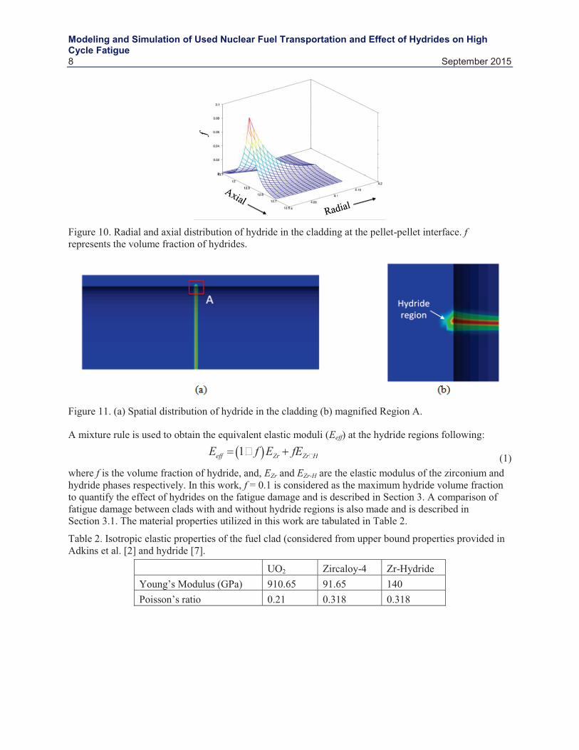
Figure 10. Radial and axial distribution of hydride in the cladding at the pellet-pellet interface. f represents the volume fraction of hydrides. .................................................................................. 8
Figure 11. (a) Spatial distribution of hydride in the cladding (b) magnified Region A. ............................... 8
Figure 12. The S-N curve following [3] is utilized in this work. .................................................................. 9
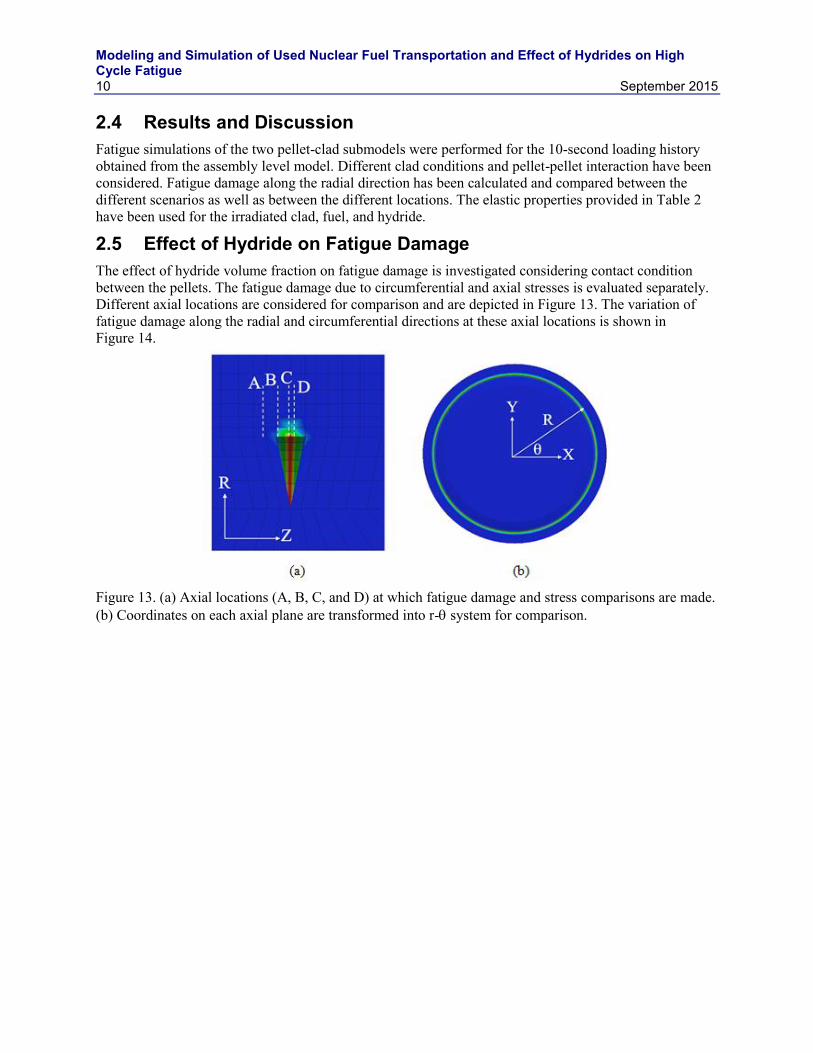
Figure 13. (a) Axial locations (A, B, C, and D) at which fatigue damage and stress comparisons are made. (b) Coordinates on each axial plane are transformed into r- system for comparison.................................................................................................................................. 10
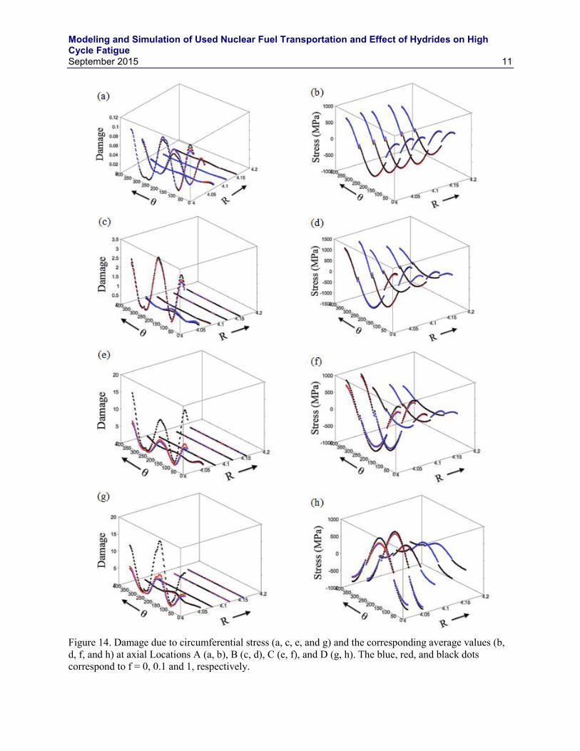
Figure 14. Damage due to circumferential stress (a, c, e, and g) and the corresponding average values (b, d, f, and h) at axial Locations A (a, b), B (c, d), C (e, f), and D (g, h). The blue, red, and black dots correspond to f = 0, 0.1 and 1, respectively. ....................................... 11
Figure 15. Comparison of fatigue damage due to circumferential stresses between contact (blue dots) and bonded (red dots) pellet-pellet interaction at Locations (a) B, (b) C, and (d) D. The fatigue damage values for the case with frictionless contact between pellets have been scaled by 10-6 to fit the plot. ............................................................................................... 12
Figure 16. Comparison of fatigue damage due to axial stresses between contact (blue-dots) and bonded (red-dots) pellet-pellet interaction at Locations (a) B, (b) C, and (d) D. The fatigue damage values for the case with frictionless contact between pellets have been scaled by 10-3 to fit the plot. ....................................................................................................... 13
Figure 17. (a) Damage distribution at Location B4 in the fuel assembly (Figure 3) for circumferential and axial stresses. (b) Comparison of slope of log-log fit to damage distribution between Locations 1 and 6 in Region B (Figure 3). ................................................ 14
Figure 18. Variation of fatigue damage due to circumferential stresses in material points located at different radial (R) and circumferential () locations at Axial Locations A, C, and D (Figure 13). ................................................................................................................................. 14
Figure 19. Variation of fatigue damage due to axial stresses in material points located at different radial (R) and circumferential () locations at Axial Locations A, C, and D (Figure 13). ......... 15
Modeling and Simulation of Used Nuclear Fuel Transportation and Effect of Hydrides on High Cycle Fatigue
September 2015 ix
Figure 20. Fatigue damage in the clad at the mid-plane (axial) of the submodel. (a) Circumferential stress; (b) Axial stress. ...................................................................................... 15
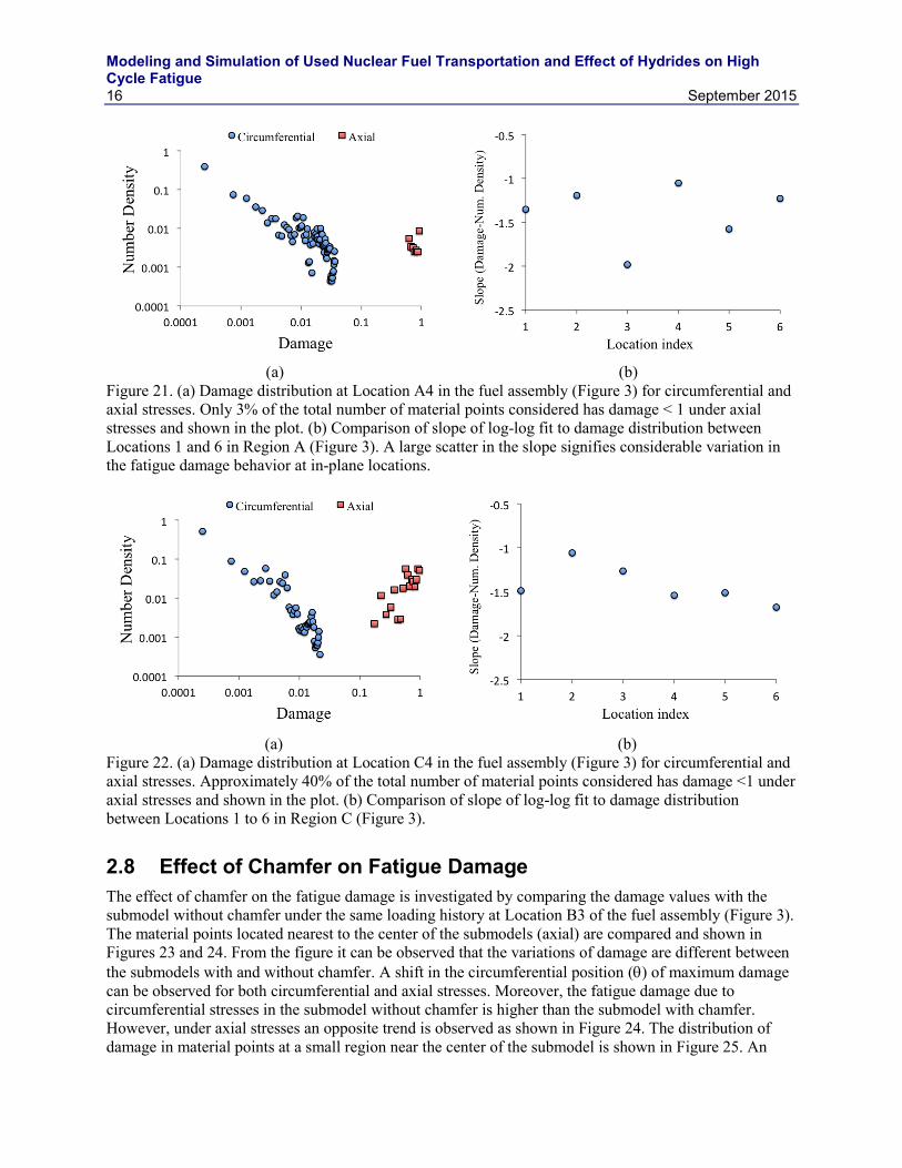
Figure 21. (a) Damage distribution at Location A4 in the fuel assembly (Figure 3) for circumferential and axial stresses. Only 3% of the total number of material points considered has damage < 1 under axial stresses and shown in the plot. (b) Comparison of slope of log-log fit to damage distribution between Locations 1 and 6 in Region A (Figure 3). A large scatter in the slope signifies considerable variation in the fatigue damage behavior at in-plane locations. ...................................................................................... 16
Figure 22. (a) Damage distribution at Location C4 in the fuel assembly (Figure 3) for circumferential and axial stresses. Approximately 40% of the total number of material points considered has damage <1 under axial stresses and shown in the plot. (b) Comparison of slope of log-log fit to damage distribution between Locations 1 to 6 in Region C (Figure 3). ................................................................................................................... 16
Figure 23. Comparison of fatigue damage due to circumferential stresses at material points nearest to the center of the submodel (axially). Without chamfer – nearest axial locations on the left (a) and right (c) of the center. With chamfer – nearest axial locations on the left (b) and right (d) of the center. .................................................................... 17
Figure 24. Comparison of fatigue damage due to axial stresses at material points nearest to the center of the submodel (axially). Without chamfer – nearest axial locations on the left (a) and right (c) of the center. With chamfer – nearest axial locations on the left (b) and right (d) of the center. ................................................................................................................. 18
Figure 25. Damage distribution within a small region in the clad near the axial center of the submodels (R = 0.25 mm, Z = 0.4 mm) at location B4 in the assembly (Figure 3). (a) Submodel without chamfer; (b) Submodel with chamfer. .......................................................... 18
Figure 26. Comparison of bending behavior of UNF rods analyzed by Adkins et al.[2]. .......................... 20
Figure 27. CIRFT testing system with horizontal U-frame. ....................................................................... 20
Figure 28. CIRFT displacement measurement and curvature calculation formulas. .................................. 21
Figure 29. UNF rod FEA modeling and pellet geometry............................................................................ 21
Figure 30. Flexural rigidity of experiment and numerical results. .............................................................. 22
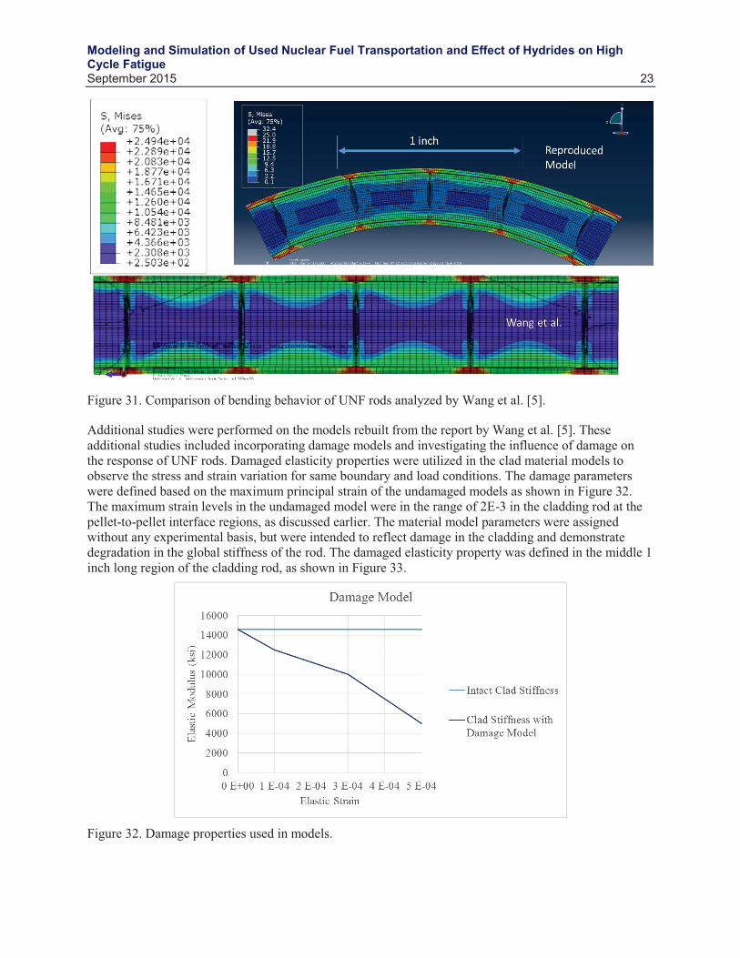
Figure 31. Comparison of bending behavior of UNF rods analyzed by Wang et al. [5]. ........................... 23
Figure 32. Damage properties used in models. ........................................................................................... 23
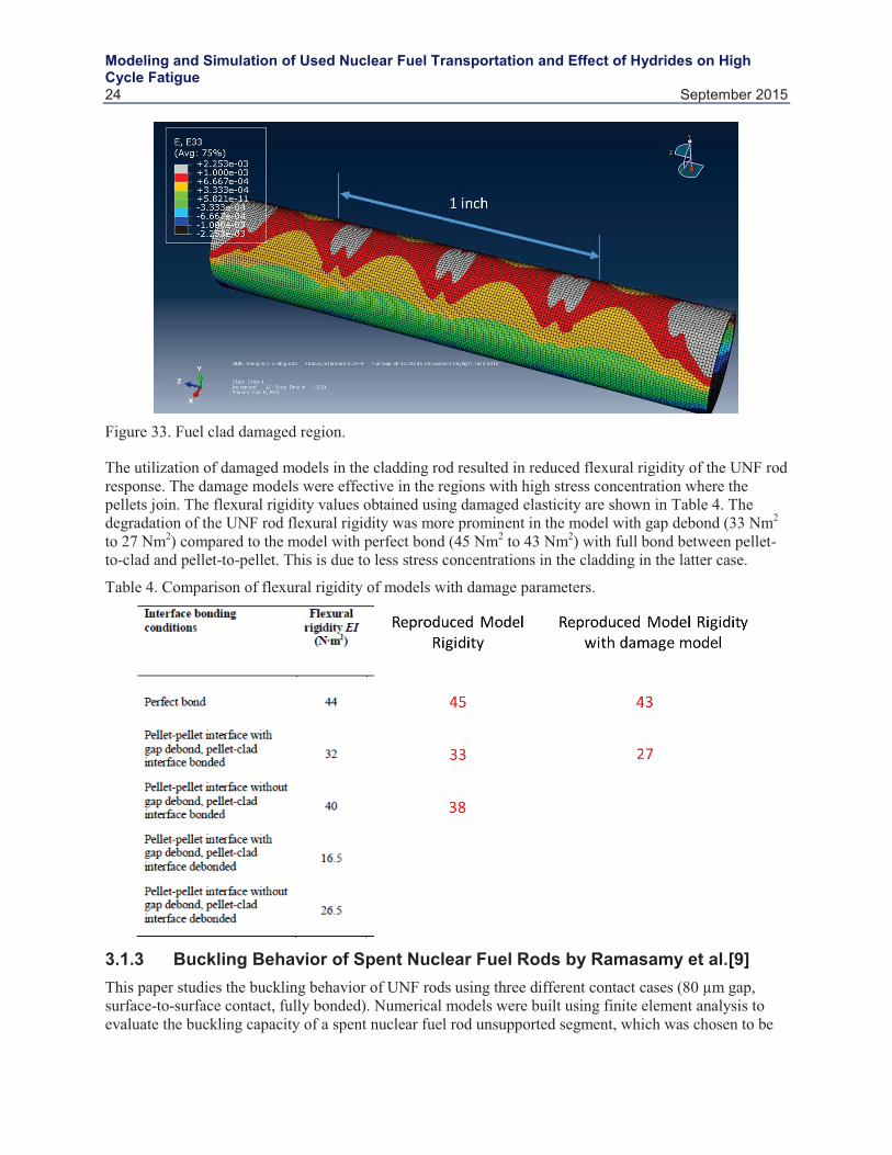
Figure 33. Fuel clad damaged region. ......................................................................................................... 24
Figure 34. UNF rod model. ......................................................................................................................... 25
Figure 35. UNF rod kinematic coupling of boundary conditions. .............................................................. 26
Figure 36. UNF rod dynamic response ....................................................................................................... 27
Figure 37. Calculated UNF rod acceleration response. ............................................................................... 27
Figure 38. UNF rod kinematic coupling of mid-point accelerations. ......................................................... 28
Figure 39. UNF rod displacement response and shape. .............................................................................. 28
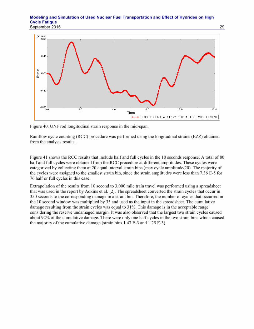
Figure 40. UNF rod longitudinal strain response in the mid-span. ............................................................. 29
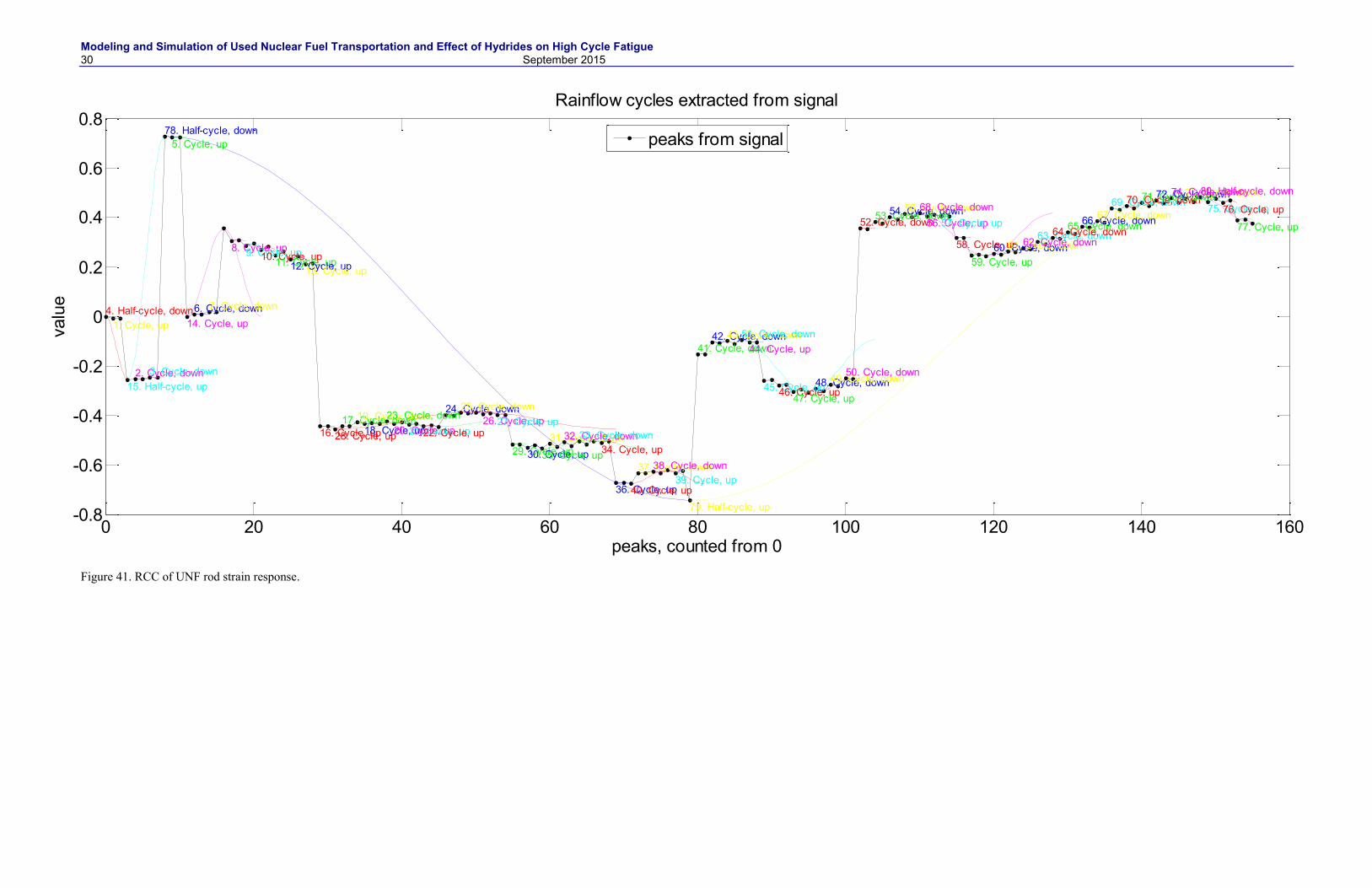
Figure 41. RCC of UNF rod strain response. .............................................................................................. 30
Modeling and Simulation of Used Nuclear Fuel Transportation and Effect of Hydrides on High Cycle Fatigue
x September 2015
Figure 42. Damage elasticity properties used in the parametric study. ....................................................... 31
Figure 43. UNF cladding damaged region. ................................................................................................. 31
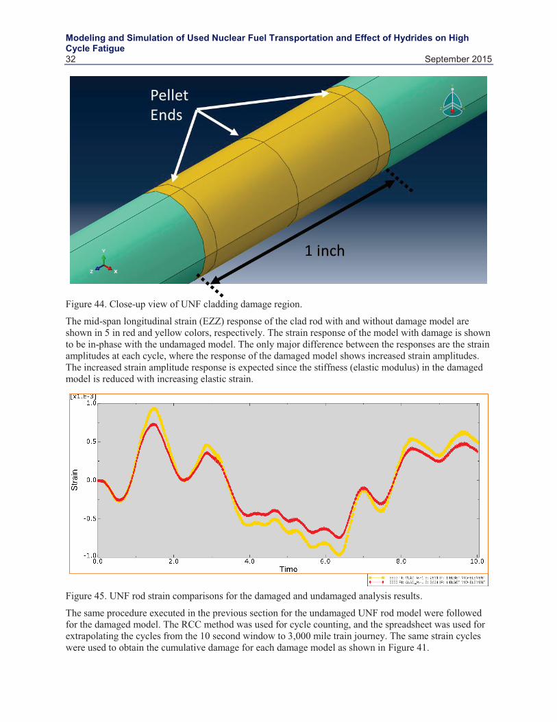
Figure 44. Close-up view of UNF cladding damage region. ...................................................................... 32
Figure 45. UNF rod strain comparisons for the damaged and undamaged analysis results. ....................... 32
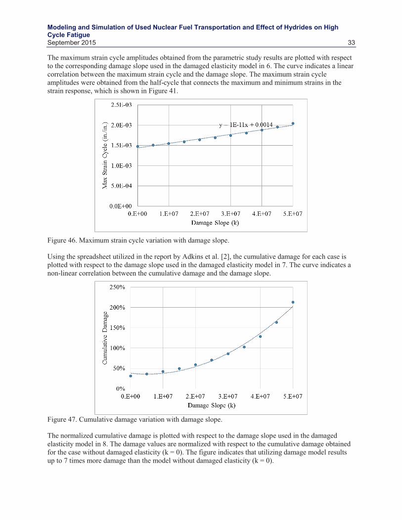
Figure 46. Maximum strain cycle variation with damage slope. ................................................................ 33
Figure 47. Cumulative damage variation with damage slope. .................................................................... 33
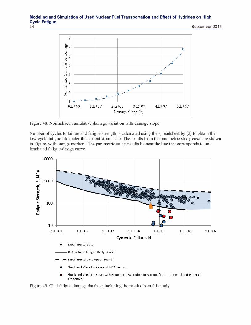
Figure 48. Normalized cumulative damage variation with damage slope. ................................................. 34
Figure 49. Clad fatigue damage database including the results from this study. ........................................ 34
TABLES Table 1. Nodal coordinates of beam elements in the assembly level model considered for
submodel analysis. The indices A–C and 1–6 corresponds to the locations highlighted in Figure 3. .................................................................................................................................... 4
Table 2. Isotropic elastic properties of the fuel clad (considered from upper bound properties provided in Adkins et al. [2] and hydride [7]. .............................................................................. 8
Table 3. Mechanical properties of fuel rods. .............................................................................................. 21
Table 4. Comparison of flexural rigidity of models with damage parameters. ........................................... 24
Modeling and Simulation of Used Nuclear Fuel Transportation and Effect of Hydrides on High Cycle Fatigue
September 2015 xi
Acronyms CIRFT cyclic integrated reversible-bending fatigue tester
DOE Department of Energy
EZZ εzz is the longitudinal strain
FE finite element
FEA finite element analysis
FEM finite element method
GWd gigawatt-days
HBU high burn-up
HCLPF high confidence in low probability of failure of high-burnup
INL Idaho National Laboratory
MTU maximum transmission unit
NCT normal conditions of transportation
ORNL Oak Ridge National Laboratory
PPC pellet-pellet-clad
PWR pressurized water reactors
R&D Research & Development
RCC rainflow cycle counting
UFDC used fuel disposition campaign
UNF used nuclear fuel
Modeling and Simulation of Used Nuclear Fuel Transportation and Effect of Hydrides on High Cycle Fatigue
September 2015 1
1. INTRODUCTION The United States nuclear contribution to the net energy production mix is approximately 20% per year. Meeting the demand every year adds to the UNF inventory. The commercial nuclear fleet consists mainly of light water reactors (pressurized water reactors [PWRs] and boiling water reactors), with estimation of approximately 140,000 maximum transmission units (MTUs) of spent nuclear discharged from the operating reactor fleet [1]. The UNF inventory is currently stored at operating commercial plants. However, the UNF fuel storage package (cask, basket, and assemblies) will be transported by rail to consolidated storage sites.
During NCT it is important to demonstrate there is a low probability of failure of high burn-up (HBU) UNF. Establishing HCLPF of UNF during transportation and extended storage requires a combination of numerical modeling and simulation and experimental tests. The numerical models need to include all material properties and material states that effect the structural dynamic performance of the UNF package. These effects include high burnup fuel elastic material properties, radial hydride formation on the cladding, and appropriate damage parameters.
One potential degradation mechanism related to cladding integrity during NCT is hydride formation on the cladding (sensitivities of hydride formation of fuel cladding are presented in Section 2). Hydrogen is absorbed into the cladding during normal operation while the fuel is in the reactor. This process occurs in conjunction with the oxidation of the cladding because of high-temperature PWR water chemistry. The corrosion itself is a problem because oxidation weakens the mechanical properties of the cladding, forming a zirconia scale. The hydrogen absorption into the zircaloy metal can lead to embrittlement. Furthermore, when the concentration of the hydrogen in the metal solution exceeds the solubility limit, the excess hydrogen precipitates out in the form of hydrides. The cladding is fabricated with a texture that ensures that these hydrides generally precipitate out in the circumferential direction upon cooldown, which has minimal effect on the cladding mechanical properties. However, reorientation of hydrides is possible under certain conditions of cladding temperature, stress state, hydrogen concentration, cooling rate, and plastic creep [3]. For example, these conditions can occur during vacuum drying process. Higher burnup fuels may experience more hydride reorientation than low burnup fuels. The formation of radial hydrides has a detrimental effect on cladding ductility, strength, and fracture toughness.
Another possible cladding degradation mechanism is temperature- and stress-related creep, leading to potential creep rupture. Tube hoop stresses initially increase when the fuel is removed from the reactor because there is no longer an external pressure to counter the internal fuel rod pressure. This situation is exacerbated during the drying process when the applied vacuum decreases the external pressure to zero and cladding temperatures increase due to loss of heat transfer fluid. Creep rupture of zircaloy cladding during vacuum drying is one of the most likely failure mechanisms [4, 5]. Over long time periods in dry storage, the cladding temperature and internal cladding pressure decrease and the creep strain rate drops to a very low value. However, tube internal pressures could increase over very long times due to release of helium (associated with alpha decay) and fission gases to the void volume inside the tubes [5]. Additional long-term cladding degradation measurements include radiation embrittlement, thermal annealing, and crud spallation.
The hydride reorientation and creep damage in the clad during storage can have detrimental effect on its cyclic fatigue behavior during transportation. Hence, a numerical study (presented in Section 2) has been undertaken in this work to provide an initial estimate of the escalated fatigue damage in the clad due to the microstructural evolutions during storage. The dry cask storage systems currently in use Westinghouse Electric 17 × 17 PWR fuel, a generic 32-PWR canister/basket model that was developed in a previous study by Adkins et al. (2013) [3], is leveraged in this study. The Nuclear Waste Technical Review Board study on the transportation plan of UNF has identified rail as the main means of transportation; thus, understanding the role of forces subjected in train/rail transportation mode on the
Modeling and Simulation of Used Nuclear Fuel Transportation and Effect of Hydrides on High Cycle Fatigue
2 September 2015
fatigue damage is necessary [4]. A representative study of a rail journey of 3,000 miles is selected in the present work based on a previous study [3], and a 10-second displacement history is used to predict the fatigue behavior in the clad.
Under used fuel disposition campaign (UFDC) Department of Energy (DOE) Office of Nuclear Energy has established necessary research and development activities related to storage, transportation, and disposal of used nuclear fuel and high-level radioactive waste [3]. The focus of this work is to understand the integrity of the UNF during transportation of UNF in the cask, by mainly:
Looking at cyclic fatigue of high burn up fuel during NCT of railroad transportation by performing the following sensitivity studies:
1. Simulating and studying the effect of contact between two chamfered pellets, and contact between chamfered pellets and clad for different scenarios.
2. Studying the effect of chamfer. 3. Studying the effect of hydride formation to the integrity of the fuel rod, and the possibility of
reorientation of metal hydrides within the cladding from circumferential to radial and analyzing high-cycle fatigue life of UNF.
4. Studying the effect of geometric flaws (cracks) at the PPC interface caused by radial hydride formation.
A detailed discussion on the used nuclear fuel loading and structural performance under normal conditions of transport is further discussed in detail in Adkins et al.’s 2013 report [3].
The scope of work covered in this report includes:
Section 2: Use of MOOSE [6], MARMOT (microstructure evolution code), and BISON (fuel performance code) to determine the impact of hydride formation at the PPC interface on UNF cladding cyclic fatigue. Section 2 includes a discussion of modeling and simulation methodology, implementation and criteria to assess fatigue failure in more detail (although this fatigue model does not degrade the material properties during dynamic simulation).
Sections 3 and 4: Presents a modeling approach in ABAQUS to evaluate the cyclic fatigue of UNF including consideration of damage criteria that degrades the material properties during dynamic simulation. This section also presents benchmarking of the ABAQUS model to pure bending test performed at ORNL, Wang, J-A and H Wang. (2013).
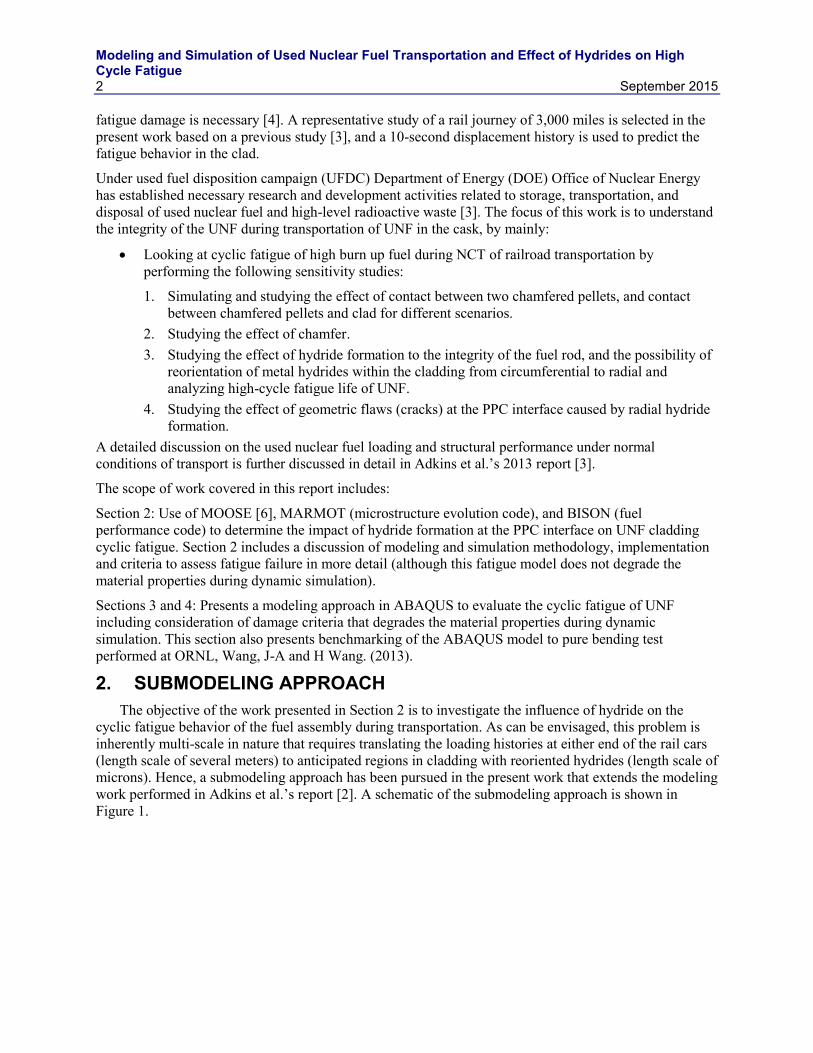
2. SUBMODELING APPROACH The objective of the work presented in Section 2 is to investigate the influence of hydride on the
cyclic fatigue behavior of the fuel assembly during transportation. As can be envisaged, this problem is inherently multi-scale in nature that requires translating the loading histories at either end of the rail cars (length scale of several meters) to anticipated regions in cladding with reoriented hydrides (length scale of microns). Hence, a submodeling approach has been pursued in the present work that extends the modeling work performed in Adkins et al.’s report [2]. A schematic of the submodeling approach is shown in Figure 1.
Modeling and Simulation of Used Nuclear Fuel Transportation and Effect of Hydrides on High Cycle Fatigue
September 2015 3
Figure 1. Schematic of the submodeling approach pursued in this work to evaluate hydride effect on fatigue life. The red-circles denote regions considered for submodeling. The rail car, basket and fuel-assembly images are taken from Adkins et al.’s report [2].
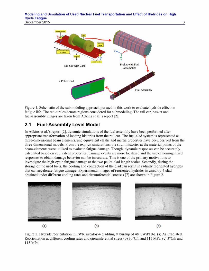
2.1 Fuel-Assembly Level Model In Adkins et al.’s report [2], dynamic simulations of the fuel assembly have been performed after appropriate transformation of loading histories from the rail car. The fuel-clad system is represented as three-dimensional beam elements, and equivalent elastic and inertia properties have been derived from the three-dimensional models. From the explicit simulations, the strain histories at the material points of the beam-elements were utilized to evaluate fatigue damage. Though, dynamic responses can be accurately calculated based on equivalent properties, damage events are more localized and the use of homogenized responses to obtain damage behavior can be inaccurate. This is one of the primary motivations to investigate the high-cycle fatigue damage at the two pellet-clad length scales. Secondly, during the storage of the used fuels, the cooling and contraction of the clad can result in radially reoriented hydrides that can accelerate fatigue damage. Experimental images of reoriented hydrides in zircaloy-4 clad obtained under different cooling rates and circumferential stresses [7] are shown in Figure 2.
Figure 2. Hydride reorientation in PWR zircaloy-4 cladding at burnup of 48 GWd/t [6]. (a) As irradiated. Reorientation at different cooling rates and circumferential stress (b) 30°C/h and 115 MPa, (c) 3°C/h and 115 MPa.
Modeling and Simulation of Used Nuclear Fuel Transportation and Effect of Hydrides on High Cycle Fatigue
4 September 2015
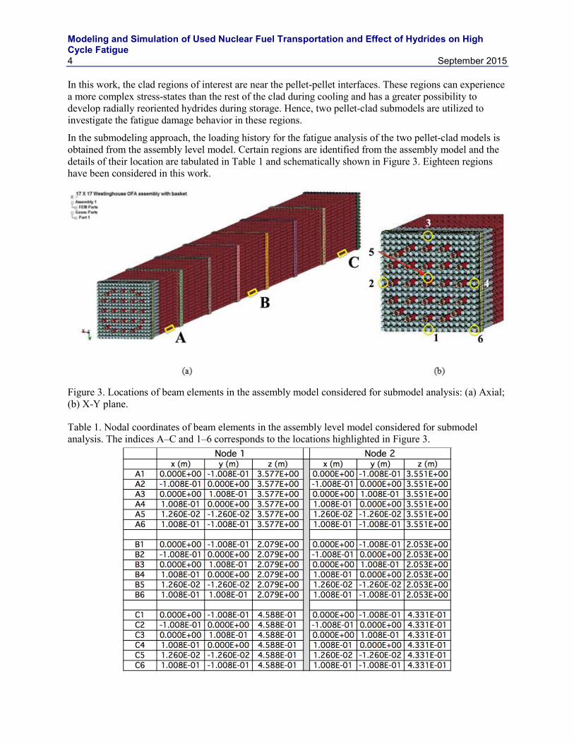
In this work, the clad regions of interest are near the pellet-pellet interfaces. These regions can experience a more complex stress-states than the rest of the clad during cooling and has a greater possibility to develop radially reoriented hydrides during storage. Hence, two pellet-clad submodels are utilized to investigate the fatigue damage behavior in these regions.
In the submodeling approach, the loading history for the fatigue analysis of the two pellet-clad models is obtained from the assembly level model. Certain regions are identified from the assembly model and the details of their location are tabulated in Table 1 and schematically shown in Figure 3. Eighteen regions have been considered in this work.
Figure 3. Locations of beam elements in the assembly model considered for submodel analysis: (a) Axial; (b) X-Y plane.
Table 1. Nodal coordinates of beam elements in the assembly level model considered for submodel analysis. The indices A–C and 1–6 corresponds to the locations highlighted in Figure 3.
Modeling and Simulation of Used Nuclear Fuel Transportation and Effect of Hydrides on High Cycle Fatigue
September 2015 5
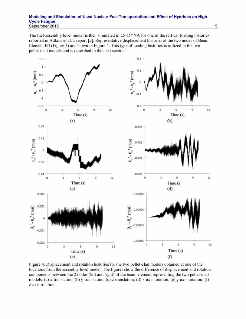
The fuel-assembly level model is then simulated in LS-DYNA for one of the rail-car loading histories reported in Adkins et al.’s report [2]. Representative displacement histories at the two nodes of Beam Element B3 (Figure 3) are shown in Figure 4. This type of loading histories is utilized in the two pellet-clad models and is described in the next section.
Figure 4. Displacement and rotation histories for the two pellet-clad models obtained at one of the locations from the assembly level model. The figures show the difference of displacement and rotation components between the 2 nodes (left and right) of the beam element representing the two pellet-clad models. (a) x-translation; (b) y-translation; (c) z-translation; (d) x-axis rotation; (e) y-axis rotation; (f) z-axis rotation.
Modeling and Simulation of Used Nuclear Fuel Transportation and Effect of Hydrides on High Cycle Fatigue
6 September 2015
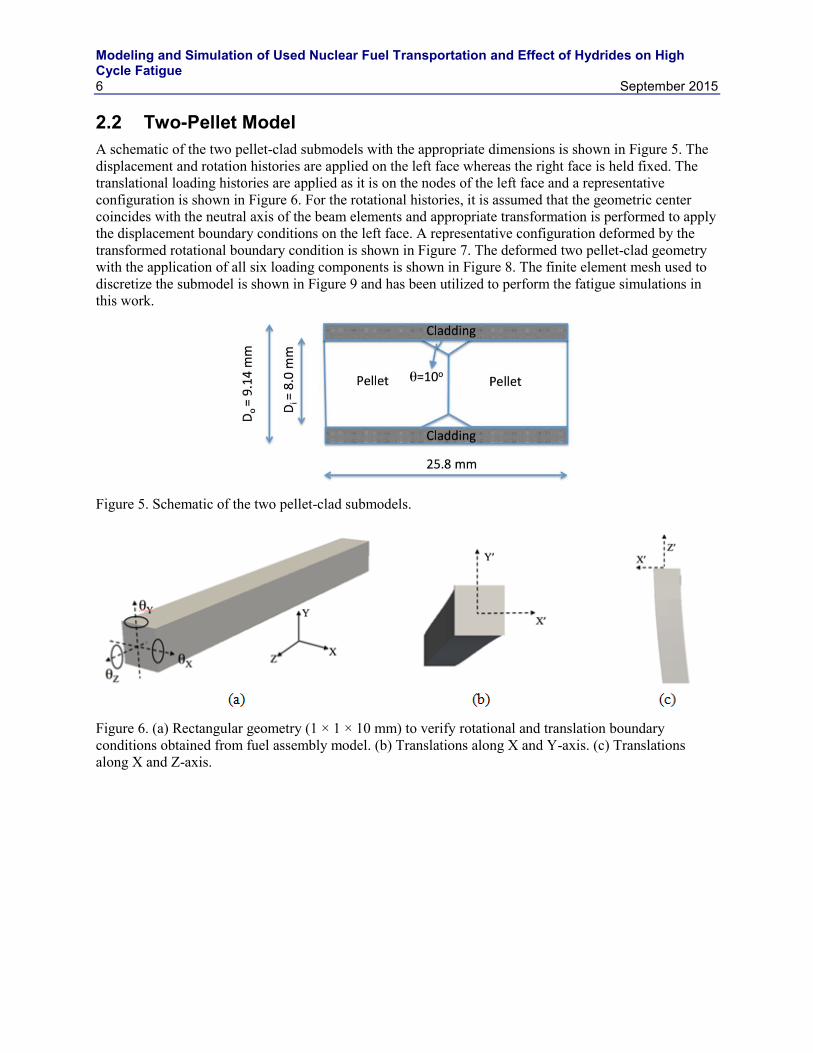
2.2 Two-Pellet Model A schematic of the two pellet-clad submodels with the appropriate dimensions is shown in Figure 5. The displacement and rotation histories are applied on the left face whereas the right face is held fixed. The translational loading histories are applied as it is on the nodes of the left face and a representative configuration is shown in Figure 6. For the rotational histories, it is assumed that the geometric center coincides with the neutral axis of the beam elements and appropriate transformation is performed to apply the displacement boundary conditions on the left face. A representative configuration deformed by the transformed rotational boundary condition is shown in Figure 7. The deformed two pellet-clad geometry with the application of all six loading components is shown in Figure 8. The finite element mesh used to discretize the submodel is shown in Figure 9 and has been utilized to perform the fatigue simulations in this work.
Figure 5. Schematic of the two pellet-clad submodels.
Figure 6. (a) Rectangular geometry (1 × 1 × 10 mm) to verify rotational and translation boundary conditions obtained from fuel assembly model. (b) Translations along X and Y-axis. (c) Translations along X and Z-axis.
Modeling and Simulation of Used Nuclear Fuel Transportation and Effect of Hydrides on High Cycle Fatigue
September 2015 7
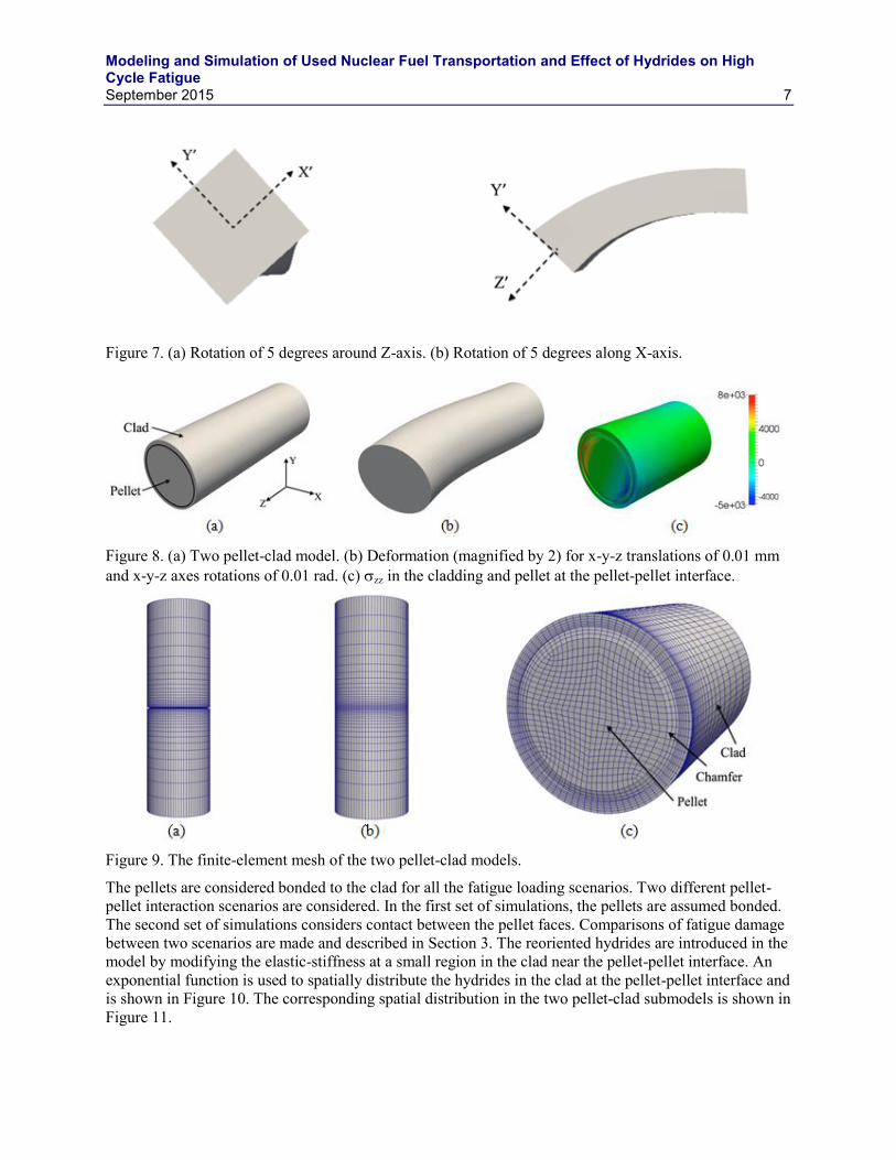
Figure 7. (a) Rotation of 5 degrees around Z-axis. (b) Rotation of 5 degrees along X-axis.
Figure 8. (a) Two pellet-clad model. (b) Deformation (magnified by 2) for x-y-z translations of 0.01 mm and x-y-z axes rotations of 0.01 rad. (c) zz in the cladding and pellet at the pellet-pellet interface.
Figure 9. The finite-element mesh of the two pellet-clad models.
The pellets are considered bonded to the clad for all the fatigue loading scenarios. Two different pellet-pellet interaction scenarios are considered. In the first set of simulations, the pellets are assumed bonded. The second set of simulations considers contact between the pellet faces. Comparisons of fatigue damage between two scenarios are made and described in Section 3. The reoriented hydrides are introduced in the model by modifying the elastic-stiffness at a small region in the clad near the pellet-pellet interface. An exponential function is used to spatially distribute the hydrides in the clad at the pellet-pellet interface and is shown in Figure 10. The corresponding spatial distribution in the two pellet-clad submodels is shown in Figure 11.
Modeling and Simulation of Used Nuclear Fuel Transportation and Effect of Hydrides on High Cycle Fatigue
Eeff f EZr fEZr H
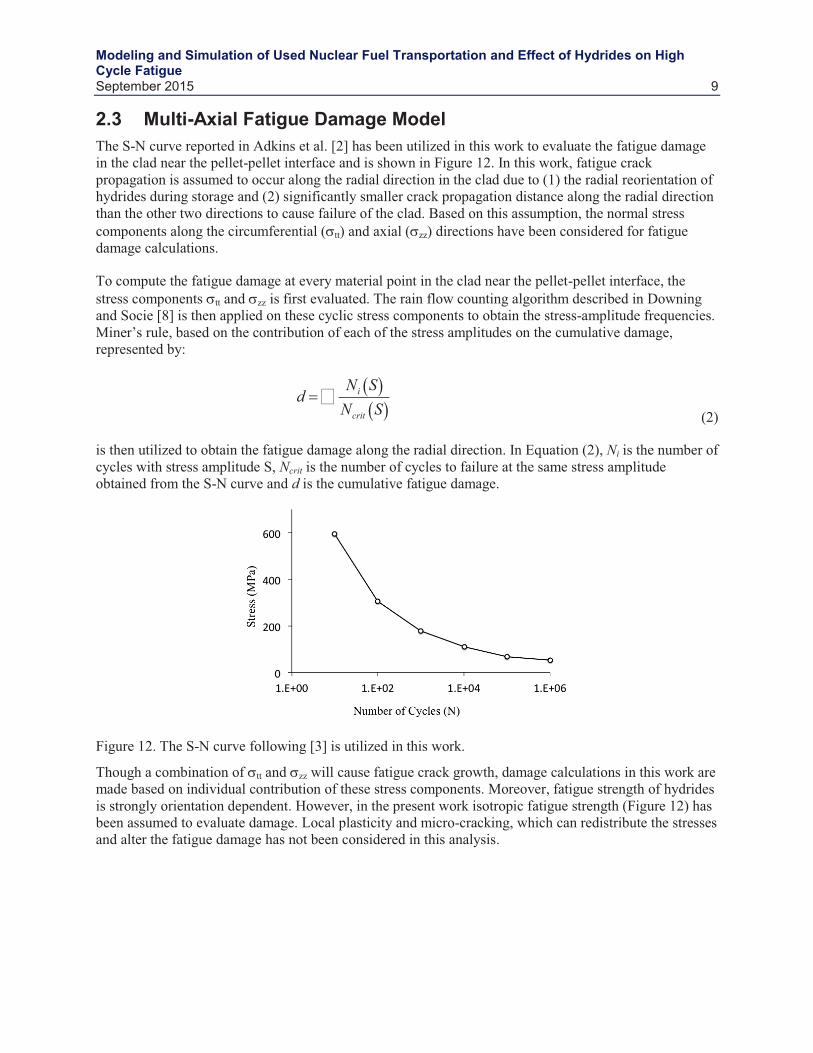
Modeling and Simulation of Used Nuclear Fuel Transportation and Effect of Hydrides on High Cycle Fatigue
dNi SNcrit S
Modeling and Simulation of Used Nuclear Fuel Transportation and Effect of Hydrides on High Cycle Fatigue
10 September 2015
2.4 Results and Discussion Fatigue simulations of the two pellet-clad submodels were performed for the 10-second loading history obtained from the assembly level model. Different clad conditions and pellet-pellet interaction have been considered. Fatigue damage along the radial direction has been calculated and compared between the different scenarios as well as between the different locations. The elastic properties provided in Table 2 have been used for the irradiated clad, fuel, and hydride.
2.5 Effect of Hydride on Fatigue Damage The effect of hydride volume fraction on fatigue damage is investigated considering contact condition between the pellets. The fatigue damage due to circumferential and axial stresses is evaluated separately. Different axial locations are considered for comparison and are depicted in Figure 13. The variation of fatigue damage along the radial and circumferential directions at these axial locations is shown in Figure 14.
Figure 13. (a) Axial locations (A, B, C, and D) at which fatigue damage and stress comparisons are made. (b) Coordinates on each axial plane are transformed into r- system for comparison.
Modeling and Simulation of Used Nuclear Fuel Transportation and Effect of Hydrides on High Cycle Fatigue
September 2015 11
Figure 14. Damage due to circumferential stress (a, c, e, and g) and the corresponding average values (b, d, f, and h) at axial Locations A (a, b), B (c, d), C (e, f), and D (g, h). The blue, red, and black dots correspond to f = 0, 0.1 and 1, respectively.
Modeling and Simulation of Used Nuclear Fuel Transportation and Effect of Hydrides on High Cycle Fatigue
12 September 2015
As can be observed from figure, the average stress and damage distribution is circumferentially non-uniform due to the directionality associated with the applied load. Some of the regions near the inner diameter of the clad show complete failure (damage > 1) within the first 4 sec of the applied load. At regions away from the clad the damage response is almost identical (Figures 14[a] and 14[c]). The effect of the modified modulus due to the hydride is fairly pronounced and leads to earlier damage (Figures 14[e] and 14[g]). In all cases, damage near the inner radius of the clad is significantly higher and decays quickly inside the clad. The effect of discontinuous properties at Locations A and B (Figure 13[a]), and free surface at Locations C and D (Figure 13[a]) contributes to this behavior. The average stresses in the fully damaged regions are also non-zero, which questions the usability of the fatigue strength data based on complete load-reversals to predict fatigue damage.
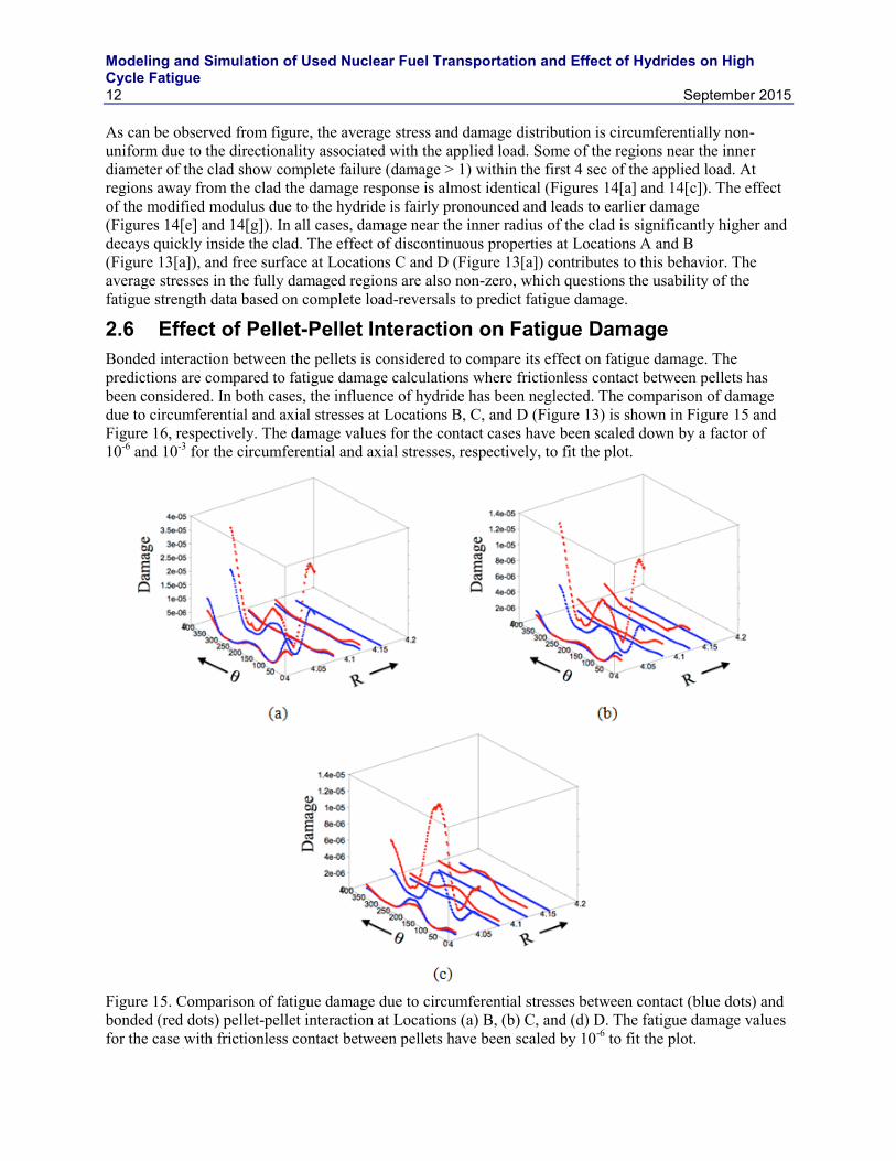
2.6 Effect of Pellet-Pellet Interaction on Fatigue Damage Bonded interaction between the pellets is considered to compare its effect on fatigue damage. The predictions are compared to fatigue damage calculations where frictionless contact between pellets has been considered. In both cases, the influence of hydride has been neglected. The comparison of damage due to circumferential and axial stresses at Locations B, C, and D (Figure 13) is shown in Figure 15 and Figure 16, respectively. The damage values for the contact cases have been scaled down by a factor of 10-6 and 10-3 for the circumferential and axial stresses, respectively, to fit the plot.
Figure 15. Comparison of fatigue damage due to circumferential stresses between contact (blue dots) and bonded (red dots) pellet-pellet interaction at Locations (a) B, (b) C, and (d) D. The fatigue damage values for the case with frictionless contact between pellets have been scaled by 10-6 to fit the plot.
Modeling and Simulation of Used Nuclear Fuel Transportation and Effect of Hydrides on High Cycle Fatigue
September 2015 13
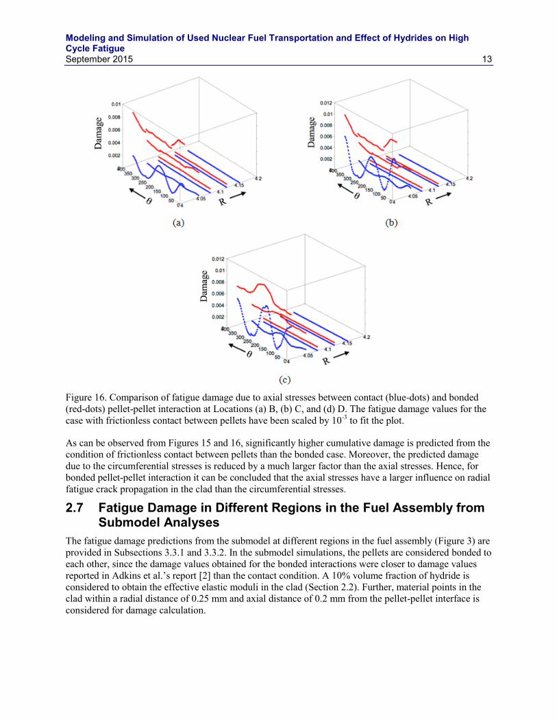
Figure 16. Comparison of fatigue damage due to axial stresses between contact (blue-dots) and bonded (red-dots) pellet-pellet interaction at Locations (a) B, (b) C, and (d) D. The fatigue damage values for the case with frictionless contact between pellets have been scaled by 10-3 to fit the plot.
As can be observed from Figures 15 and 16, significantly higher cumulative damage is predicted from the condition of frictionless contact between pellets than the bonded case. Moreover, the predicted damage due to the circumferential stresses is reduced by a much larger factor than the axial stresses. Hence, for bonded pellet-pellet interaction it can be concluded that the axial stresses have a larger influence on radial fatigue crack propagation in the clad than the circumferential stresses.
2.7 Fatigue Damage in Different Regions in the Fuel Assembly from Submodel Analyses
The fatigue damage predictions from the submodel at different regions in the fuel assembly (Figure 3) are provided in Subsections 3.3.1 and 3.3.2. In the submodel simulations, the pellets are considered bonded to each other, since the damage values obtained for the bonded interactions were closer to damage values reported in Adkins et al.’s report [2] than the contact condition. A 10% volume fraction of hydride is considered to obtain the effective elastic moduli in the clad (Section 2.2). Further, material points in the clad within a radial distance of 0.25 mm and axial distance of 0.2 mm from the pellet-pellet interface is considered for damage calculation.
Modeling and Simulation of Used Nuclear Fuel Transportation and Effect of Hydrides on High Cycle Fatigue
14 September 2015
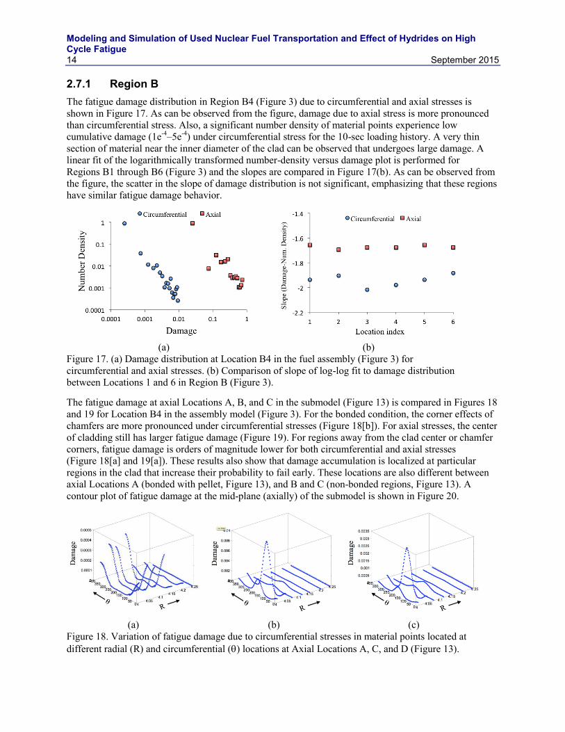
2.7.1 Region B The fatigue damage distribution in Region B4 (Figure 3) due to circumferential and axial stresses is shown in Figure 17. As can be observed from the figure, damage due to axial stress is more pronounced than circumferential stress. Also, a significant number density of material points experience low cumulative damage (1e-4–5e-4) under circumferential stress for the 10-sec loading history. A very thin section of material near the inner diameter of the clad can be observed that undergoes large damage. A linear fit of the logarithmically transformed number-density versus damage plot is performed for Regions B1 through B6 (Figure 3) and the slopes are compared in Figure 17(b). As can be observed from the figure, the scatter in the slope of damage distribution is not significant, emphasizing that these regions have similar fatigue damage behavior.
(a) (b)
Figure 17. (a) Damage distribution at Location B4 in the fuel assembly (Figure 3) for circumferential and axial stresses. (b) Comparison of slope of log-log fit to damage distribution between Locations 1 and 6 in Region B (Figure 3).
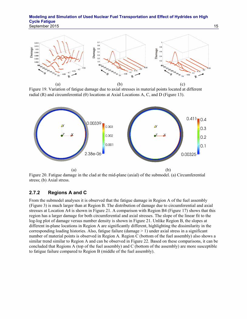
The fatigue damage at axial Locations A, B, and C in the submodel (Figure 13) is compared in Figures 18 and 19 for Location B4 in the assembly model (Figure 3). For the bonded condition, the corner effects of chamfers are more pronounced under circumferential stresses (Figure 18[b]). For axial stresses, the center of cladding still has larger fatigue damage (Figure 19). For regions away from the clad center or chamfer corners, fatigue damage is orders of magnitude lower for both circumferential and axial stresses (Figure 18[a] and 19[a]). These results also show that damage accumulation is localized at particular regions in the clad that increase their probability to fail early. These locations are also different between axial Locations A (bonded with pellet, Figure 13), and B and C (non-bonded regions, Figure 13). A contour plot of fatigue damage at the mid-plane (axially) of the submodel is shown in Figure 20.
(a) (b) (c)
Figure 18. Variation of fatigue damage due to circumferential stresses in material points located at different radial (R) and circumferential () locations at Axial Locations A, C, and D (Figure 13).
Modeling and Simulation of Used Nuclear Fuel Transportation and Effect of Hydrides on High Cycle Fatigue
September 2015 15
(a) (b) (c)
Figure 19. Variation of fatigue damage due to axial stresses in material points located at different radial (R) and circumferential () locations at Axial Locations A, C, and D (Figure 13).
(a) (b)
Figure 20. Fatigue damage in the clad at the mid-plane (axial) of the submodel. (a) Circumferential stress; (b) Axial stress.
2.7.2 Regions A and C From the submodel analyses it is observed that the fatigue damage in Region A of the fuel assembly (Figure 3) is much larger than at Region B. The distribution of damage due to circumferential and axial stresses at Location A4 is shown in Figure 21. A comparison with Region B4 (Figure 17) shows that this region has a larger damage for both circumferential and axial stresses. The slope of the linear fit to the log-log plot of damage versus number density is shown in Figure 21. Unlike Region B, the slopes at different in-plane locations in Region A are significantly different, highlighting the dissimilarity in the corresponding loading histories. Also, fatigue failure (damage > 1) under axial stress in a significant number of material points is observed in Region A. Region C (bottom of the fuel assembly) also shows a similar trend similar to Region A and can be observed in Figure 22. Based on these comparisons, it can be concluded that Regions A (top of the fuel assembly) and C (bottom of the assembly) are more susceptible to fatigue failure compared to Region B (middle of the fuel assembly).
Modeling and Simulation of Used Nuclear Fuel Transportation and Effect of Hydrides on High Cycle Fatigue
16 September 2015
(a) (b)
Figure 21. (a) Damage distribution at Location A4 in the fuel assembly (Figure 3) for circumferential and axial stresses. Only 3% of the total number of material points considered has damage < 1 under axial stresses and shown in the plot. (b) Comparison of slope of log-log fit to damage distribution between Locations 1 and 6 in Region A (Figure 3). A large scatter in the slope signifies considerable variation in the fatigue damage behavior at in-plane locations.
(a) (b)
Figure 22. (a) Damage distribution at Location C4 in the fuel assembly (Figure 3) for circumferential and axial stresses. Approximately 40% of the total number of material points considered has damage <1 under axial stresses and shown in the plot. (b) Comparison of slope of log-log fit to damage distribution between Locations 1 to 6 in Region C (Figure 3).
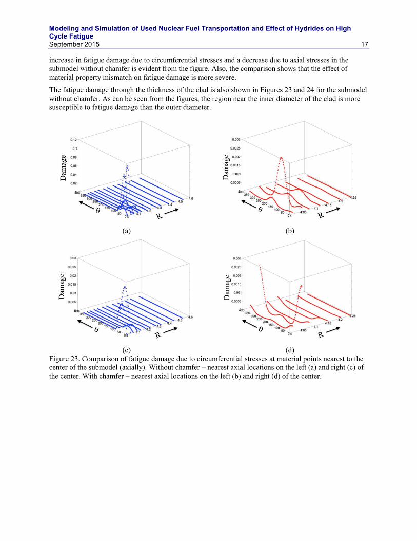
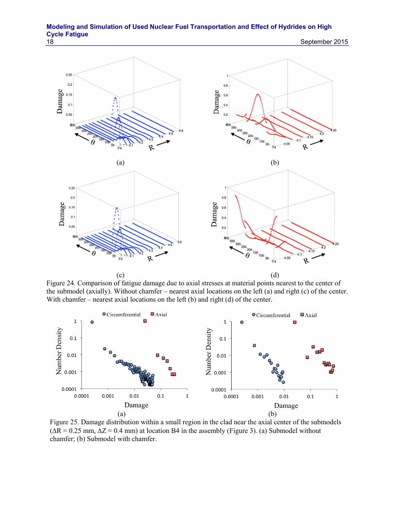
2.8 Effect of Chamfer on Fatigue Damage The effect of chamfer on the fatigue damage is investigated by comparing the damage values with the submodel without chamfer under the same loading history at Location B3 of the fuel assembly (Figure 3). The material points located nearest to the center of the submodels (axial) are compared and shown in Figures 23 and 24. From the figure it can be observed that the variations of damage are different between the submodels with and without chamfer. A shift in the circumferential position () of maximum damage can be observed for both circumferential and axial stresses. Moreover, the fatigue damage due to circumferential stresses in the submodel without chamfer is higher than the submodel with chamfer. However, under axial stresses an opposite trend is observed as shown in Figure 24. The distribution of damage in material points at a small region near the center of the submodel is shown in Figure 25. An
Modeling and Simulation of Used Nuclear Fuel Transportation and Effect of Hydrides on High Cycle Fatigue
September 2015 17
increase in fatigue damage due to circumferential stresses and a decrease due to axial stresses in the submodel without chamfer is evident from the figure. Also, the comparison shows that the effect of material property mismatch on fatigue damage is more severe.
The fatigue damage through the thickness of the clad is also shown in Figures 23 and 24 for the submodel without chamfer. As can be seen from the figures, the region near the inner diameter of the clad is more susceptible to fatigue damage than the outer diameter.
(a) (b)
(c) (d)
Figure 23. Comparison of fatigue damage due to circumferential stresses at material points nearest to the center of the submodel (axially). Without chamfer – nearest axial locations on the left (a) and right (c) of the center. With chamfer – nearest axial locations on the left (b) and right (d) of the center.
Modeling and Simulation of Used Nuclear Fuel Transportation and Effect of Hydrides on High Cycle Fatigue
18 September 2015
(a) (b)
(c) (d)
Figure 24. Comparison of fatigue damage due to axial stresses at material points nearest to the center of the submodel (axially). Without chamfer – nearest axial locations on the left (a) and right (c) of the center. With chamfer – nearest axial locations on the left (b) and right (d) of the center.
(a) (b)
Figure 25. Damage distribution within a small region in the clad near the axial center of the submodels (R = 0.25 mm, Z = 0.4 mm) at location B4 in the assembly (Figure 3). (a) Submodel without chamfer; (b) Submodel with chamfer.
Modeling and Simulation of Used Nuclear Fuel Transportation and Effect of Hydrides on High Cycle Fatigue
September 2015 19
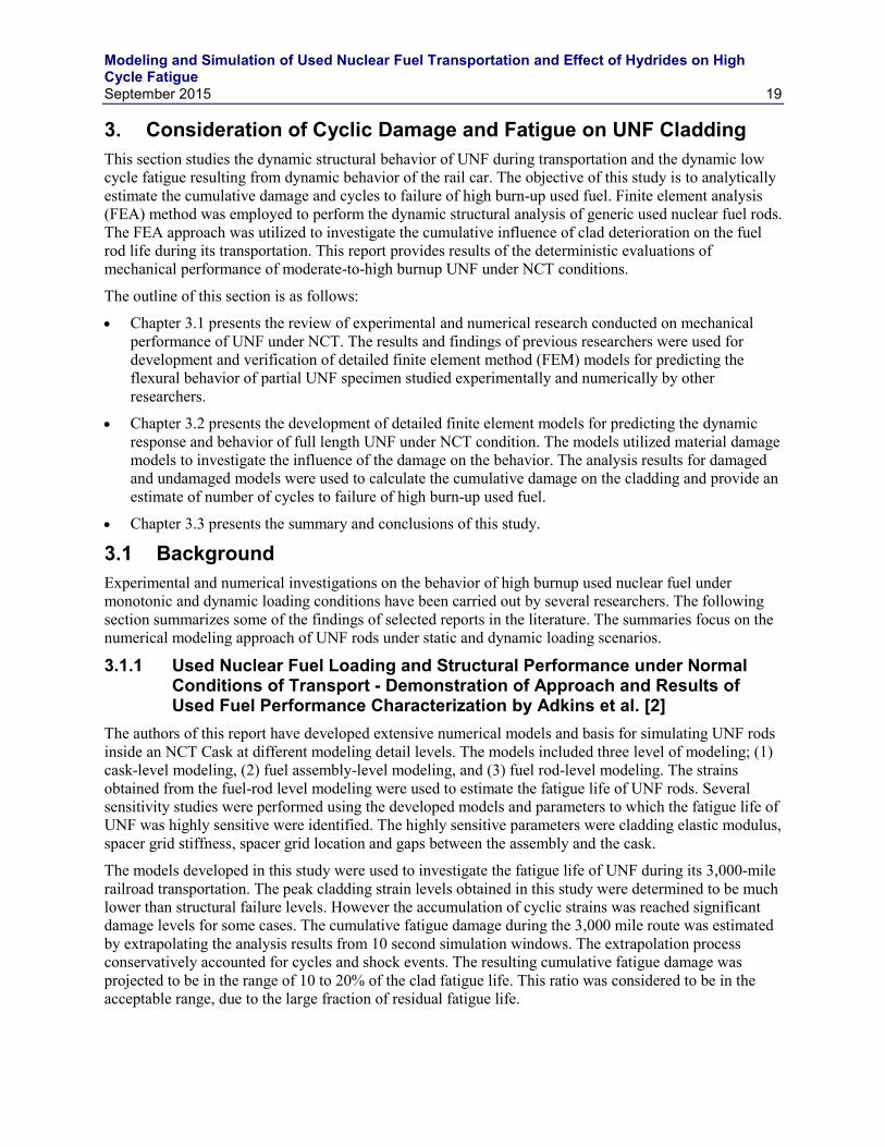
3. Consideration of Cyclic Damage and Fatigue on UNF Cladding This section studies the dynamic structural behavior of UNF during transportation and the dynamic low cycle fatigue resulting from dynamic behavior of the rail car. The objective of this study is to analytically estimate the cumulative damage and cycles to failure of high burn-up used fuel. Finite element analysis (FEA) method was employed to perform the dynamic structural analysis of generic used nuclear fuel rods. The FEA approach was utilized to investigate the cumulative influence of clad deterioration on the fuel rod life during its transportation. This report provides results of the deterministic evaluations of mechanical performance of moderate-to-high burnup UNF under NCT conditions.
The outline of this section is as follows:
Chapter 3.1 presents the review of experimental and numerical research conducted on mechanical performance of UNF under NCT. The results and findings of previous researchers were used for development and verification of detailed finite element method (FEM) models for predicting the flexural behavior of partial UNF specimen studied experimentally and numerically by other researchers.
Chapter 3.2 presents the development of detailed finite element models for predicting the dynamic response and behavior of full length UNF under NCT condition. The models utilized material damage models to investigate the influence of the damage on the behavior. The analysis results for damaged and undamaged models were used to calculate the cumulative damage on the cladding and provide an estimate of number of cycles to failure of high burn-up used fuel.
Chapter 3.3 presents the summary and conclusions of this study.
3.1 Background Experimental and numerical investigations on the behavior of high burnup used nuclear fuel under monotonic and dynamic loading conditions have been carried out by several researchers. The following section summarizes some of the findings of selected reports in the literature. The summaries focus on the numerical modeling approach of UNF rods under static and dynamic loading scenarios.
3.1.1 Used Nuclear Fuel Loading and Structural Performance under Normal Conditions of Transport - Demonstration of Approach and Results of Used Fuel Performance Characterization by Adkins et al. [2]
The authors of this report have developed extensive numerical models and basis for simulating UNF rods inside an NCT Cask at different modeling detail levels. The models included three level of modeling; (1) cask-level modeling, (2) fuel assembly-level modeling, and (3) fuel rod-level modeling. The strains obtained from the fuel-rod level modeling were used to estimate the fatigue life of UNF rods. Several sensitivity studies were performed using the developed models and parameters to which the fatigue life of UNF was highly sensitive were identified. The highly sensitive parameters were cladding elastic modulus, spacer grid stiffness, spacer grid location and gaps between the assembly and the cask.
The models developed in this study were used to investigate the fatigue life of UNF during its 3,000-mile railroad transportation. The peak cladding strain levels obtained in this study were determined to be much lower than structural failure levels. However the accumulation of cyclic strains was reached significant damage levels for some cases. The cumulative fatigue damage during the 3,000 mile route was estimated by extrapolating the analysis results from 10 second simulation windows. The extrapolation process conservatively accounted for cycles and shock events. The resulting cumulative fatigue damage was projected to be in the range of 10 to 20% of the clad fatigue life. This ratio was considered to be in the acceptable range, due to the large fraction of residual fatigue life.
Modeling and Simulation of Used Nuclear Fuel Transportation and Effect of Hydrides on High Cycle Fatigue
20 September 2015
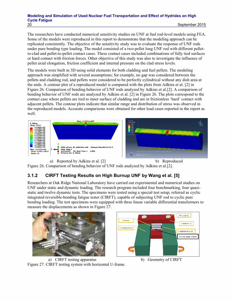
The researchers have conducted numerical sensitivity studies on UNF at fuel rod-level models using FEA. Some of the models were reproduced in this report to demonstrate that the modeling approach can be replicated consistently. The objective of the sensitivity study was to evaluate the response of UNF rods under pure bending type loading. The model consisted of a two-pellet long UNF rod with different pellet-to-clad and pellet-to-pellet contact cases. These contact cases included combinations of fully tied surfaces or hard contact with friction forces. Other objective of this study was also to investigate the influence of pellet axial elongation, friction coefficient and internal pressure on the clad stress levels.
The models were built in 3D using solid elements for both cladding and fuel pellets. The modeling approach was simplified with several assumptions; for example, no gap was considered between the pellets and cladding rod, and pellets were considered to be perfectly cylindrical without any dish area at the ends. A contour plot of a reproduced model is compared with the plots from Adkins et al. [2] in Figure 26. Comparison of bending behavior of UNF rods analyzed by Adkins et al.[2]. A comparison of bending behavior of UNF rods are analyzed by Adkins et al. [2] in Figure 26. The plots correspond to the contact case where pellets are tied to inner surface of cladding and are in frictionless ‘hard’ contact with adjacent pellets. The contour plots indicate that similar range and distribution of stress was observed in the reproduced models. Accurate comparisons were obtained for other load cases reported in the report as well.
a) Reported by Adkins et al. [2] b) Reproduced
Figure 26. Comparison of bending behavior of UNF rods analyzed by Adkins et al.[2].
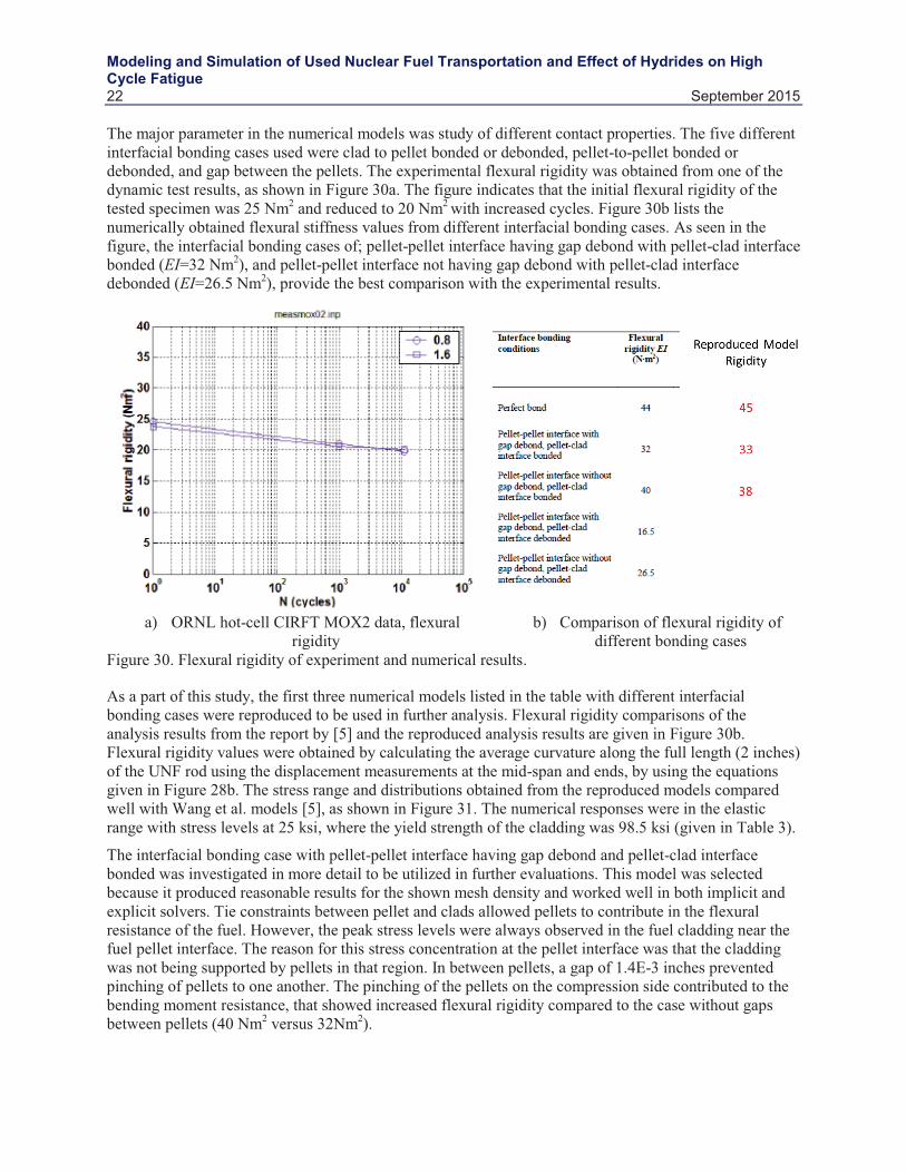
3.1.2 CIRFT Testing Results on High Burnup UNF by Wang et al. [5] Researchers at Oak Ridge National Laboratory have carried out experimental and numerical studies on UNF under static and dynamic loading. The research program included four benchmarking, four quasi-static and twelve dynamic tests. The specimens were tested using a special test setup, referred as cyclic integrated reversible-bending fatigue tester (CIRFT), capable of subjecting UNF rod to cyclic pure bending loading. The test specimens were equipped with three linear variable differential transformers to measure the displacements as shown in Figure 27.
a) CIRFT testing apparatus b) Geometry of CIRFT
Figure 27. CIRFT testing system with horizontal U-frame.

Modeling and Simulation of Used Nuclear Fuel Transportation and Effect of Hydrides on High Cycle Fatigue
Modeling and Simulation of Used Nuclear Fuel Transportation and Effect of Hydrides on High Cycle Fatigue
Modeling and Simulation of Used Nuclear Fuel Transportation and Effect of Hydrides on High Cycle Fatigue
Modeling and Simulation of Used Nuclear Fuel Transportation and Effect of Hydrides on High Cycle Fatigue
Modeling and Simulation of Used Nuclear Fuel Transportation and Effect of Hydrides on High Cycle Fatigue
September 2015 25
21 inches long. Geometric imperfections were included in buckling capacity analyses to account for initial imperfections and creep deflection after long term storage.
The results indicate that buckling capacity of fuel rods increases when pellet-cladding interaction is taken into account, and decreases as initial imperfections increase. The results from this numerical study also demonstrate that the buckling capacity of the fuel road is controlled by elastic buckling. Therefore, the authors support fuel-rod material degradation mechanisms is not critical for evaluating buckling capacity. These models were used as guidance but were not reproduced since the buckling behavior did not demonstrate the need for damage models and buckling behavior was not the focus of this particular study.
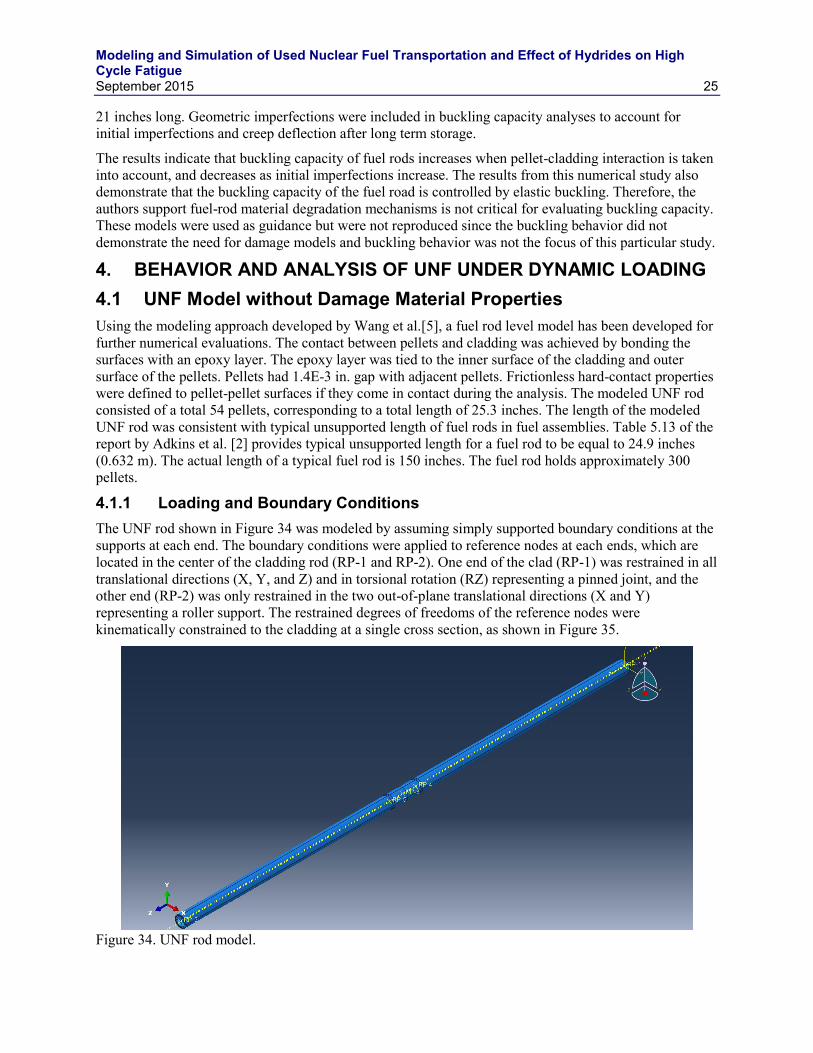
4. BEHAVIOR AND ANALYSIS OF UNF UNDER DYNAMIC LOADING 4.1 UNF Model without Damage Material Properties Using the modeling approach developed by Wang et al.[5], a fuel rod level model has been developed for further numerical evaluations. The contact between pellets and cladding was achieved by bonding the surfaces with an epoxy layer. The epoxy layer was tied to the inner surface of the cladding and outer surface of the pellets. Pellets had 1.4E-3 in. gap with adjacent pellets. Frictionless hard-contact properties were defined to pellet-pellet surfaces if they come in contact during the analysis. The modeled UNF rod consisted of a total 54 pellets, corresponding to a total length of 25.3 inches. The length of the modeled UNF rod was consistent with typical unsupported length of fuel rods in fuel assemblies. Table 5.13 of the report by Adkins et al. [2] provides typical unsupported length for a fuel rod to be equal to 24.9 inches (0.632 m). The actual length of a typical fuel rod is 150 inches. The fuel rod holds approximately 300 pellets.
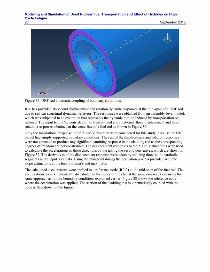
4.1.1 Loading and Boundary Conditions The UNF rod shown in Figure 34 was modeled by assuming simply supported boundary conditions at the supports at each end. The boundary conditions were applied to reference nodes at each ends, which are located in the center of the cladding rod (RP-1 and RP-2). One end of the clad (RP-1) was restrained in all translational directions (X, Y, and Z) and in torsional rotation (RZ) representing a pinned joint, and the other end (RP-2) was only restrained in the two out-of-plane translational directions (X and Y) representing a roller support. The restrained degrees of freedoms of the reference nodes were kinematically constrained to the cladding at a single cross section, as shown in Figure 35.
Figure 34. UNF rod model.
Modeling and Simulation of Used Nuclear Fuel Transportation and Effect of Hydrides on High Cycle Fatigue
26 September 2015
Figure 35. UNF rod kinematic coupling of boundary conditions.
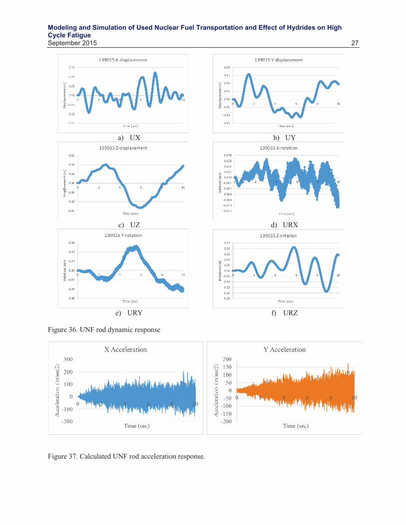
INL has provided 10-second displacement and rotation dynamic responses at the mid-span of a UNF rod due to rail car structural dynamic behavior. The responses were obtained from an assembly-level model, which was subjected to an excitation that represents the dynamic motion induced by transportation on railroad. The input from INL consisted of all translational and rotational (three displacement and three rotation) responses obtained at the centerline of a fuel rod as shown in Figure 36.
Only the translational response in the X and Y direction were considered for this study, because the UNF model had simply supported boundary conditions. The rest of the displacement and rotation responses were not expected to produce any significant straining response in the cladding rod as the corresponding degrees of freedom are not constrained. The displacement responses in the X and Y directions were used to calculate the accelerations in these directions by the taking the second derivatives, which are shown in Figure 37. The derivatives of the displacement response were taken by utilizing three-point parabolic segments in the input X-Y data. Using the mid-point during the derivation process provided accurate slope estimations at the local minima’s and maxima’s.
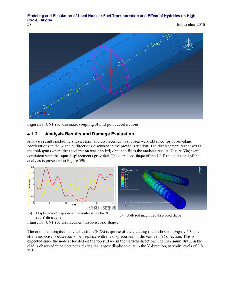
The calculated accelerations were applied to a reference node (RP-3) at the mid-span of the fuel rod. The accelerations were kinematically distributed to the nodes of the clad at the same cross-section, using the same approach as for the boundary conditions explained earlier. Figure 38 shows the reference node where the acceleration was applied. The section of the cladding that is kinematically coupled with the node is also shown in the figure.
Modeling and Simulation of Used Nuclear Fuel Transportation and Effect of Hydrides on High Cycle Fatigue
Modeling and Simulation of Used Nuclear Fuel Transportation and Effect of Hydrides on High Cycle Fatigue
28 September 2015
Figure 38. UNF rod kinematic coupling of mid-point accelerations.
4.1.2 Analysis Results and Damage Evaluation Analysis results including stress, strain and displacement responses were obtained for out-of-plane accelerations in the X and Y directions discussed in the previous section. The displacement responses at the mid-span (where the acceleration was applied) obtained from the analysis results (Figure 39a) were consistent with the input displacements provided. The displaced shape of the UNF rod at the end of the analysis is presented in Figure 39b.
a) Displacement response at the mid-span in the X
and Y directions b) UNF rod magnified displaced shape
Figure 39. UNF rod displacement response and shape.
The mid-span longitudinal elastic strain (EZZ) response of the cladding rod is shown in Figure 40. The strain response is observed to be in-phase with the displacement in the vertical (Y) direction. This is expected since the node is located on the top surface in the vertical direction. The maximum strain in the clad is observed to be occurring during the largest displacements in the Y direction, at strain levels of 0.8 E-3.
Modeling and Simulation of Used Nuclear Fuel Transportation and Effect of Hydrides on High Cycle Fatigue
September 2015 29
Figure 40. UNF rod longitudinal strain response in the mid-span.
Rainflow cycle counting (RCC) procedure was performed using the longitudinal strains (EZZ) obtained from the analysis results.
Figure 41 shows the RCC results that include half and full cycles in the 10 seconds response. A total of 80 half and full cycles were obtained from the RCC procedure at different amplitudes. These cycles were categorized by collecting them at 20 equal interval strain bins (max cycle amplitude/20). The majority of the cycles were assigned to the smallest strain bin, since the strain amplitudes were less than 7.36 E-5 for 76 half or full cycles in this case.
Extrapolation of the results from 10 second to 3,000 mile train travel was performed using a spreadsheet that was used in the report by Adkins et al. [2]. The spreadsheet converted the strain cycles that occur in 350 seconds to the corresponding damage in a strain bin. Therefore, the number of cycles that occurred in the 10 second window was multiplied by 35 and used as the input in the spreadsheet. The cumulative damage resulting from the strain cycles was equal to 31%. This damage is in the acceptable range considering the reserve undamaged margin. It was also observed that the largest two strain cycles caused about 92% of the cumulative damage. There were only one half cycles in the two strain bins which caused the majority of the cumulative damage (strain bins 1.47 E-3 and 1.25 E-3).
Modeling and Simulation of Used Nuclear Fuel Transportation and Effect of Hydrides on High Cycle Fatigue
30 September 2015
0 20 40 60 80 100 120 140 160-0.8
-0.6
-0.4
-0.2
0
0.2
0.4
0.6
0.8
1. Cycle, up
2. Cycle, down3. Cycle, down
4. Half-cycle, down
5. Cycle, up
6. Cycle, down7. Cycle, down
8. Cycle, up9. Cycle, up10. Cycle, up11. Cycle, up12. Cycle, up13. Cycle, up
14. Cycle, up
15. Half-cycle, up
16. Cycle, up17. Cycle, down
18. Cycle, up19. Cycle, down
20. Cycle, up21. Cycle, up22. Cycle, up
23. Cycle, down24. Cycle, down25. Cycle, down26. Cycle, up27. Cycle, up
28. Cycle, up29. Cycle, up30. Cycle, up
31. Cycle, down32. Cycle, down33. Cycle, down34. Cycle, up35. Cycle, up
36. Cycle, up
37. Cycle, down38. Cycle, down39. Cycle, up
40. Cycle, up
41. Cycle, down42. Cycle, down43. Cycle, down
44. Cycle, up
45. Cycle, up46. Cycle, up47. Cycle, up48. Cycle, down49. Cycle, down50. Cycle, down
51. Cycle, down
52. Cycle, down53. Cycle, down54. Cycle, down55. Cycle, down56. Cycle, up57. Cycle, up
58. Cycle, up
59. Cycle, up60. Cycle, down61. Cycle, down62. Cycle, down63. Cycle, down64. Cycle, down65. Cycle, down66. Cycle, down67. Cycle, down
68. Cycle, down 69. Cycle, down70. Cycle, down71. Cycle, down72. Cycle, down73. Cycle, down74. Cycle, down75. Cycle, up76. Cycle, up
77. Cycle, up
78. Half-cycle, down
79. Half-cycle, up
80. Half-cycle, down
peaks, counted from 0
valu
e
Rainflow cycles extracted from signal
peaks from signal
Figure 41. RCC of UNF rod strain response.
Modeling and Simulation of Used Nuclear Fuel Transportation and Effect of Hydrides on High Cycle Fatigue
Modeling and Simulation of Used Nuclear Fuel Transportation and Effect of Hydrides on High Cycle Fatigue
Modeling and Simulation of Used Nuclear Fuel Transportation and Effect of Hydrides on High Cycle Fatigue
Modeling and Simulation of Used Nuclear Fuel Transportation and Effect of Hydrides on High Cycle Fatigue
Modeling and Simulation of Used Nuclear Fuel Transportation and Effect of Hydrides on High Cycle Fatigue
September 2015 35
5. CONCLUSION This report studies the effect of pellet geometry, pellet-pellet interaction, and hydrides on the high-cycle fatigue damage of used fuel during transportation. Experimental investigations have revealed that radial reorientation of hydrides can reduce the fracture strength significantly. Since the propagation of fatigue cracks from radially oriented hydrides will be most strongly influence the normal component of the local circumferential and axial stresses, the fatigue damage model presented in Section 2 is based on these stress components transformed from the submodel simulations in MOOSE. The rain-flow counting and the Miner’s rule are applied on the cyclic stress components to evaluate the fatigue damage values. In the Miner’s rule, an isotropic fatigue strength curve for the clad without distinction between the zircaloy and hydride phases has been utilized to evaluate damage.
In Section 2 the effect of hydride has been incorporated by modifying the elastic-modulus in a small region in the clad near the pellet-pellet interface and has been observed to accelerate fatigue damage in Section 2.1. Comparison of fatigue damage has been made between submodels considering bonded and contact interaction between pellets in Section 2.2. From the comparison, it is observed that contact conditions significantly increase the fatigue damage. Since the fatigue damage for the bonded pellet-pellet interaction is observed to be closer to values obtained in Adkins et al.’s report [2], this condition has been assumed to evaluate fatigue damage in different regions discussed in Section 2.3. The effect of chamfer on fatigue damage has been evaluated in Section 2.4. The results for one of the regions indicate that fatigue damage due to circumferential stresses reduces because of the presence of chamfer, whereas it increases for loading from axial stresses.
This report also presents the review of experimental and numerical research programs conducted on mechanical performance of high burnup UNF under normal transport. The results and findings of previous researchers were corroborated and expanded to be used for considering damage parameters in modeling:
The damage model results indicated that most of the damage was caused by the large amplitude cycles, with the largest two amplitudes being responsible for more than 90% of the cumulative damage.
The cumulative damage was influenced by the damage parameters (the damage slope level) used in the models.
The number of cycles for fatigue failure is comparable to the un-irradiated fatigue-design curve provided by Adkins et al. [2].
The results reported in this work provide interesting trends in the cyclic fatigue behavior of the clad. It appears from the analyses that fatigue crack initiation can happen near the inner diameter of the clad and propagate outwards. Also, there is a large difference in the fatigue damage between the circumferential and axial directions. Hence, anisotropic fatigue strength data considering hydride orientation is necessary to provide more realistic predictions. Contrary to the expected behavior, the geometry without the chamfer resulted in an increased fatigue damage due to circumferential stresses than the chamfered geometry. Hence, the presence of geometric discontinuities like chamfer may not be the dominant factor controlling fatigue damage, however inclusion of individual pellets is important. Though some insight into the local fatigue behavior of the used fuels can be obtained from this work, more conclusive results would require lower length scale analyses using models with localized plasticity and fatigue crack growth. Information on the state of the fuel-pellet system before transportation can further improve the fatigue damage predictions.
Modeling and Simulation of Used Nuclear Fuel Transportation and Effect of Hydrides on High Cycle Fatigue
36 September 2015
6. REFERENCES 1. Carter J. T., A. J. Luptak, J. Gastelum, C. Stockman, and A. Miller, 2012, Fuel Cycle Potential
Waste Inventory for Disposition, FCR&D-USED-2010-000031, Rev. 5, U.S. Department of Energy, Washington, D.C., July 2012.
2. Adkins H. A., K. Geelhood, B. Koeppel, J. Coleman, J. Bignell, G. Flores, J. Wang, S. Sanborn, R. Spears, N. Klymyshyn, 2013, Used Nuclear Fuel Loading and Structural Performance Under Normal Conditions of Transport – Demonstration of Approach and Results on Used Fuel Performance Characterization, FCRD-UFD-2013-000325, U.S. Department of Energy, Washington D.C., April 1, 2013.
3. NWTRB, 2010, Evaluation of the Technical Basis for Extended Dry Storage and Transportation of Used Nuclear Fuel, United States Nuclear Waste Technical Review Board, December 2010.
4. O’Brien, J. E., D. Phetteplace, M. Sprenger, and H. Welland, 1994, ICPP-603 Fuel Canning Project May Street South Vacuum Drying Mockup Station Test Report Document, Project File No. 015635, September 1994.
5. Wang, J. A. and H, Wang, (2013). Progress Report on Reversal Bending Fatigue Testing of Zry-4 Surrogate Rod (Out-of-Cell Fatigue Testing Development, Task 2.4), ORNL/TM-2013/297, Oak Ridge National Laboratory, Oak Ridge, TN.
6. Masaki A., Toshikazu B., Toshiyasu M., Katsuichiro K., Takayoshi Y., Shinohara Y., 2008. “Evaluation of Hydride Reorientation Behavior and Mechanical Properties for High-Burnup Fuel-Cladding Tubes in Interim Dry Storage,” Journal of ASTM International, Vol. 5. No. 9, Paper ID JAI101262.
7. Yamanaka S., Yoshioka K., Uno M, 1999. “Isotope effects on the physicochemical properties of zirconium hydride,” Journal of Alloys and Compounds, Vol. 293–295, pp. 908–914.
8. Downing S. D., Socie D. F., 1982. “Simple rainflow counting algorithms,” International Journal of Fatigue, Vol. 4, Issue 1, pp. 31–40.
9. Ramasamy, U., Ibarra, L.F., and Medina, R. (2015). Buckling Behaviour of Spent Nuclear Fuel Rods. Trans of SMiRT 23, IASMiRT.