Embed Size (px)
Citation preview
Modeling Complex Shapes in Autodesk® Revit®
Structure Using the Conceptual Massing Environment
Jeremiah Bowles – Black & Veatch Engineering
SE1511-L This hands-on lab focuses on using the conceptual massing environment in Revit Structure
software to create complex roofs and walls and other complex shapes, such as a transmission tower or
even a battleship. We walk through creating the mass framework and then get into the project. We
explore advanced techniques to make trusses, complex beams, and columns that host the mass
constructs. We also explore the workflow of how to manage change with these tools and how to master
these techniques.
Learning Objectives: At the end of this class, you will be able to:
• List key tools and describe key strategies in conceptual massing
• Model complex shapes, including roofs, walls, and complex framing
• Create an optimized workflow for using conceptual massing and structural layout
• Use conceptual massing as a change management tool for complex geometry exploration
About the Speaker
Jeremiah works out of the CIO Group at Black & Veatch Engineering a global EPC Firm. He is
a Corporate BIM Design & Construction Technologies Manager & leader in innovation and
productivity solutions for our skilled BIM & VDC group. He is also working to complete a MS in
Project Management with an Emphasis in Construction Management at KU Graduate School of
Engineering and is an Adjunct Instructor with JCCC. He is BIM an Autodesk & Technology
Implementation specialists, with a diverse portfolio of experience in Architecture, Engineering &
Construction since 1992. As an early BIM adopter and innovator he is always looking beyond
the technology utilization norms and has focused on value delivery to his clients. His
experience in team development, change management and business acumen allow him drive
meaningful change at Black & Veatch. [email protected]
Modeling Complex Shapes in Autodesk® Revit®
2
Contents Learning Objectives: ............................................................................................................... 1
About the Speaker .................................................................................................................. 1
Creating a Mass surface ......................................................................................................... 3
Conceptual Massing 101 ..................................................................................................... 3
Building Maker tools ............................................................................................................ 3
Massing Tools ..................................................................................................................... 4
Lofted forms ........................................................................................................................ 5
Sweeps and blends ............................................................................................................. 5
NURBS ............................................................................................................................... 6
Point manipulation tools ...................................................................................................... 6
Lab 1 Creating a Mass surface ............................................................................................... 7
Creating a Roof From Surface ...........................................................................................11
Lessons Learned ...............................................................................................................13
Some newer Tools.................................................................................................................13
Divide Path ........................................................................................................................13
Surface Nodes ...................................................................................................................13
Dissolve .............................................................................................................................13
Lab 2 Tower Lab ...................................................................................................................14
Tower Considerations / Planning .......................................................................................18
Lab 3 Millennial “Bean” (Bonus Lab) ......................................................................................19
Modeling Complex Shapes in Autodesk® Revit®
3
Creating a Mass surface
Conceptual Massing 101
As the conceptual massing tools (formerly building maker) have come of age these tools offer
enhanced modeling capabilities. Although these Revit has always had the ability to create mass
forms, with the ability to prototype mass forms in a separate family and enhanced free form
modeling tools (beyond the traditional extrusion, sweep, blend, & sweep blend tools) found in
the standard Revit families.
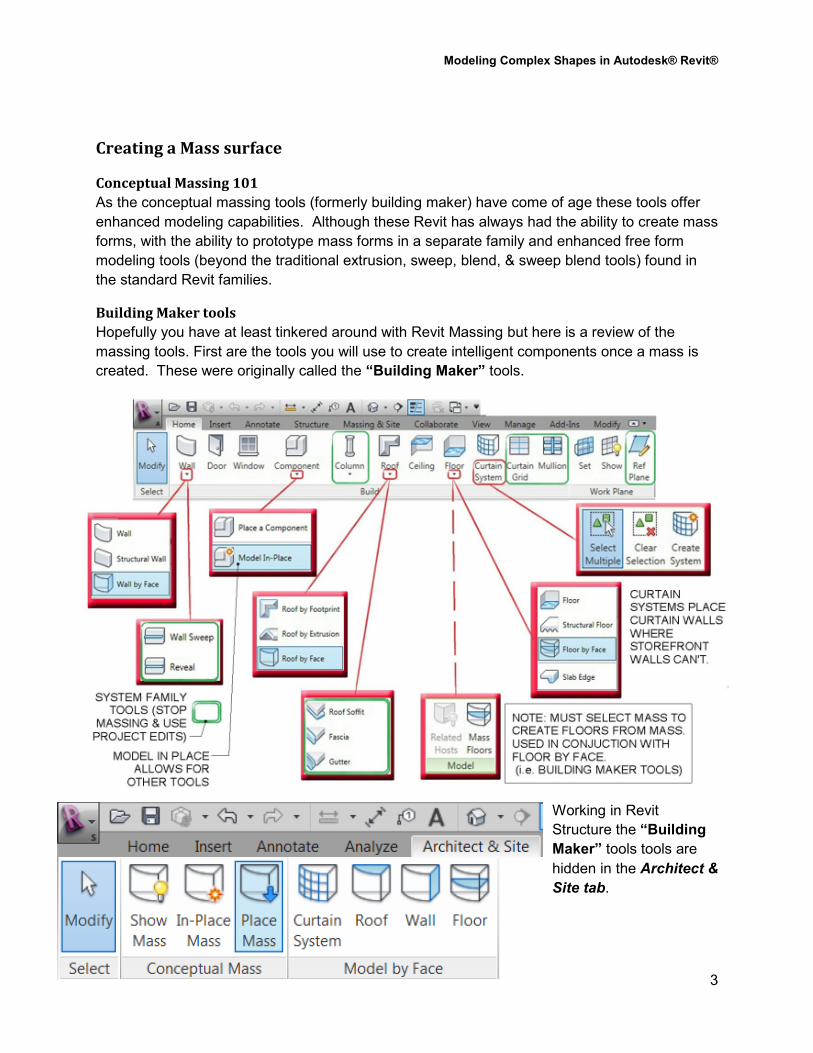
Building Maker tools
Hopefully you have at least tinkered around with Revit Massing but here is a review of the
massing tools. First are the tools you will use to create intelligent components once a mass is
created. These were originally called the “Building Maker” tools.
Working in Revit
Structure the “Building
Maker” tools tools are
hidden in the Architect &
Site tab.
Modeling Complex Shapes in Autodesk® Revit®
4
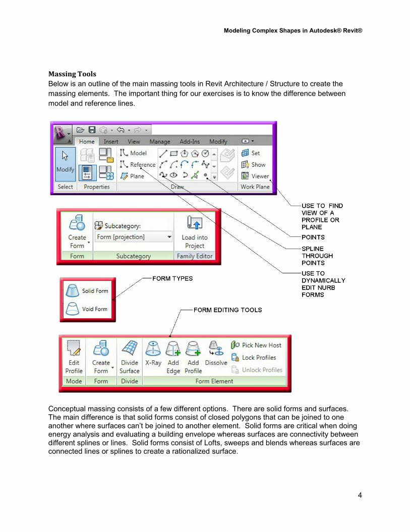
Massing Tools
Below is an outline of the main massing tools in Revit Architecture / Structure to create the
massing elements. The important thing for our exercises is to know the difference between
model and reference lines.
Conceptual massing consists of a few different options. There are solid forms and surfaces. The main difference is that solid forms consist of closed polygons that can be joined to one another where surfaces can’t be joined to another element. Solid forms are critical when doing energy analysis and evaluating a building envelope whereas surfaces are connectivity between different splines or lines. Solid forms consist of Lofts, sweeps and blends whereas surfaces are connected lines or splines to create a rationalized surface.
Modeling Complex Shapes in Autodesk® Revit®
5
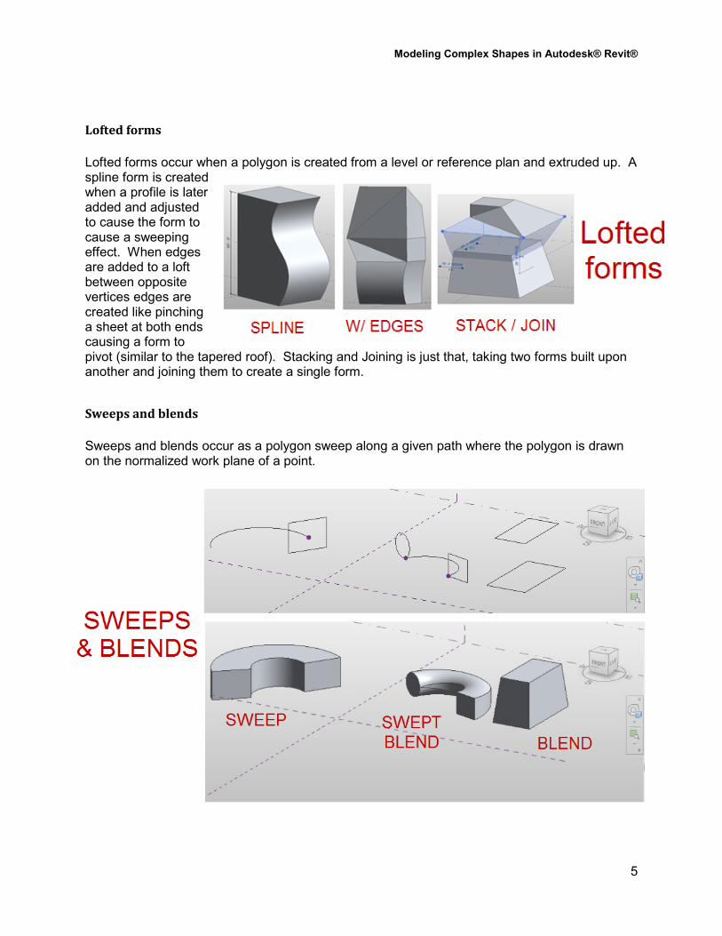
Lofted forms
Lofted forms occur when a polygon is created from a level or reference plan and extruded up. A spline form is created when a profile is later added and adjusted to cause the form to cause a sweeping effect. When edges are added to a loft between opposite vertices edges are created like pinching a sheet at both ends causing a form to pivot (similar to the tapered roof). Stacking and Joining is just that, taking two forms built upon another and joining them to create a single form.
Sweeps and blends
Sweeps and blends occur as a polygon sweep along a given path where the polygon is drawn on the normalized work plane of a point.
Modeling Complex Shapes in Autodesk® Revit®
6
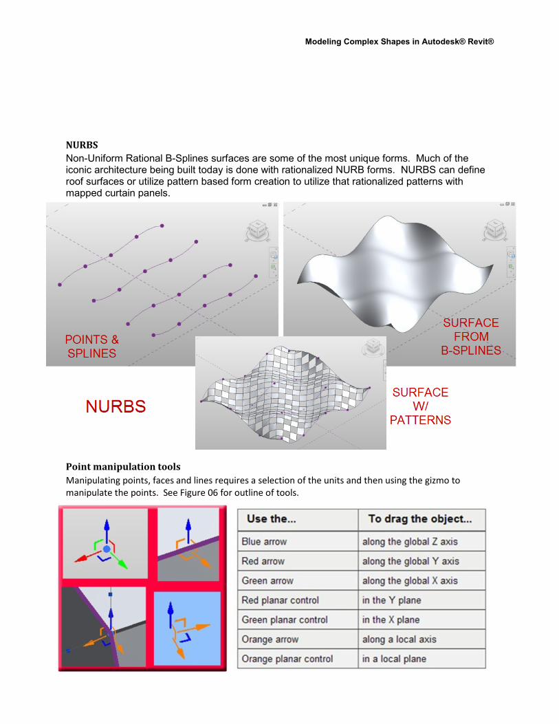
NURBS
Non-Uniform Rational B-Splines surfaces are some of the most unique forms. Much of the iconic architecture being built today is done with rationalized NURB forms. NURBS can define roof surfaces or utilize pattern based form creation to utilize that rationalized patterns with mapped curtain panels.
Point manipulation tools
Manipulating points, faces and lines requires a selection of the units and then using the gizmo to
manipulate the points. See Figure 06 for outline of tools.
Modeling Complex Shapes in Autodesk® Revit®
7
Lab 1 Creating a Mass surface
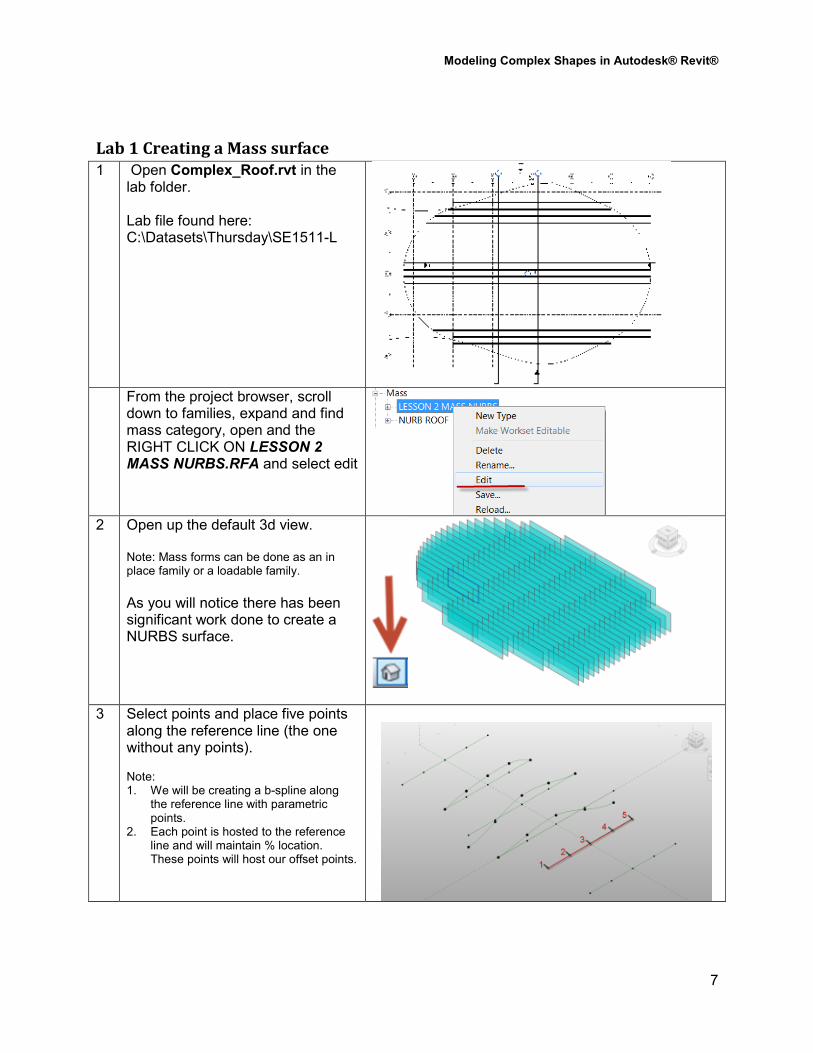
1 Open Complex_Roof.rvt in the lab folder. Lab file found here: C:\Datasets\Thursday\SE1511-L
From the project browser, scroll
down to families, expand and find mass category, open and the RIGHT CLICK ON LESSON 2 MASS NURBS.RFA and select edit
2 Open up the default 3d view. Note: Mass forms can be done as an in place family or a loadable family.
As you will notice there has been significant work done to create a NURBS surface.
3 Select points and place five points along the reference line (the one without any points). Note: 1. We will be creating a b-spline along
the reference line with parametric points.
2. Each point is hosted to the reference line and will maintain % location. These points will host our offset points.
Modeling Complex Shapes in Autodesk® Revit®
8
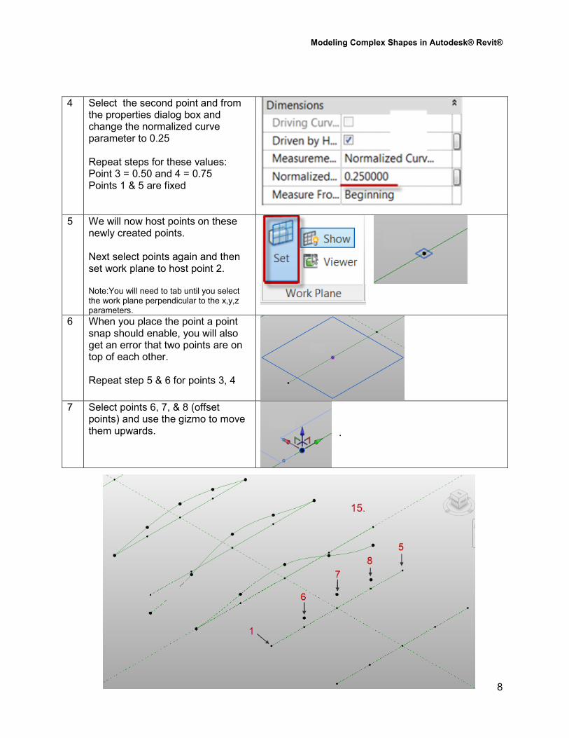
4 Select the second point and from the properties dialog box and change the normalized curve parameter to 0.25 Repeat steps for these values: Point 3 = 0.50 and 4 = 0.75 Points 1 & 5 are fixed
5 We will now host points on these newly created points. Next select points again and then set work plane to host point 2. Note:You will need to tab until you select the work plane perpendicular to the x,y,z parameters.
6 When you place the point a point snap should enable, you will also get an error that two points are on top of each other. Repeat step 5 & 6 for points 3, 4
7 Select points 6, 7, & 8 (offset
points) and use the gizmo to move them upwards.
.
Modeling Complex Shapes in Autodesk® Revit®
9
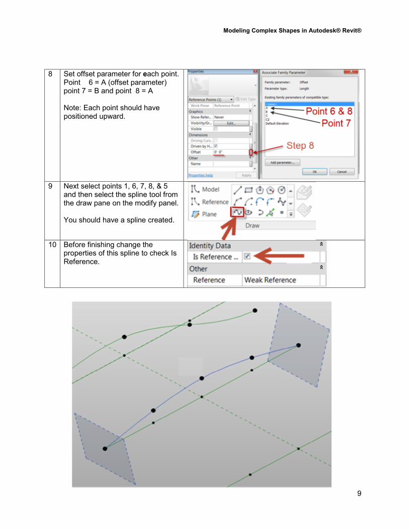
8 Set offset parameter for each point. Point 6 = A (offset parameter) point 7 = B and point 8 = A Note: Each point should have positioned upward.
9 Next select points 1, 6, 7, 8, & 5
and then select the spline tool from the draw pane on the modify panel. You should have a spline created.
10 Before finishing change the
properties of this spline to check Is Reference.
Modeling Complex Shapes in Autodesk® Revit®
10
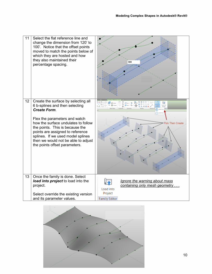
11 Select the flat reference line and change the dimension from 120’ to 100’. Notice that the offset points moved to match the points below of which they are hosted and how they also maintained their percentage spacing.
12 Create the surface by selecting all
6 b-splines and then selecting Create Form. Flex the parameters and watch how the surface undulates to follow the points. This is because the points are assigned to reference splines. If we used model splines then we would not be able to adjust the points offset parameters.
13 Once the family is done. Select
load into project to load into the project. Select override the existing version and its parameter values.
Ignore the warning about mass containing only mesh geometry . . .
Modeling Complex Shapes in Autodesk® Revit®
11
Creating a Roof From Surface
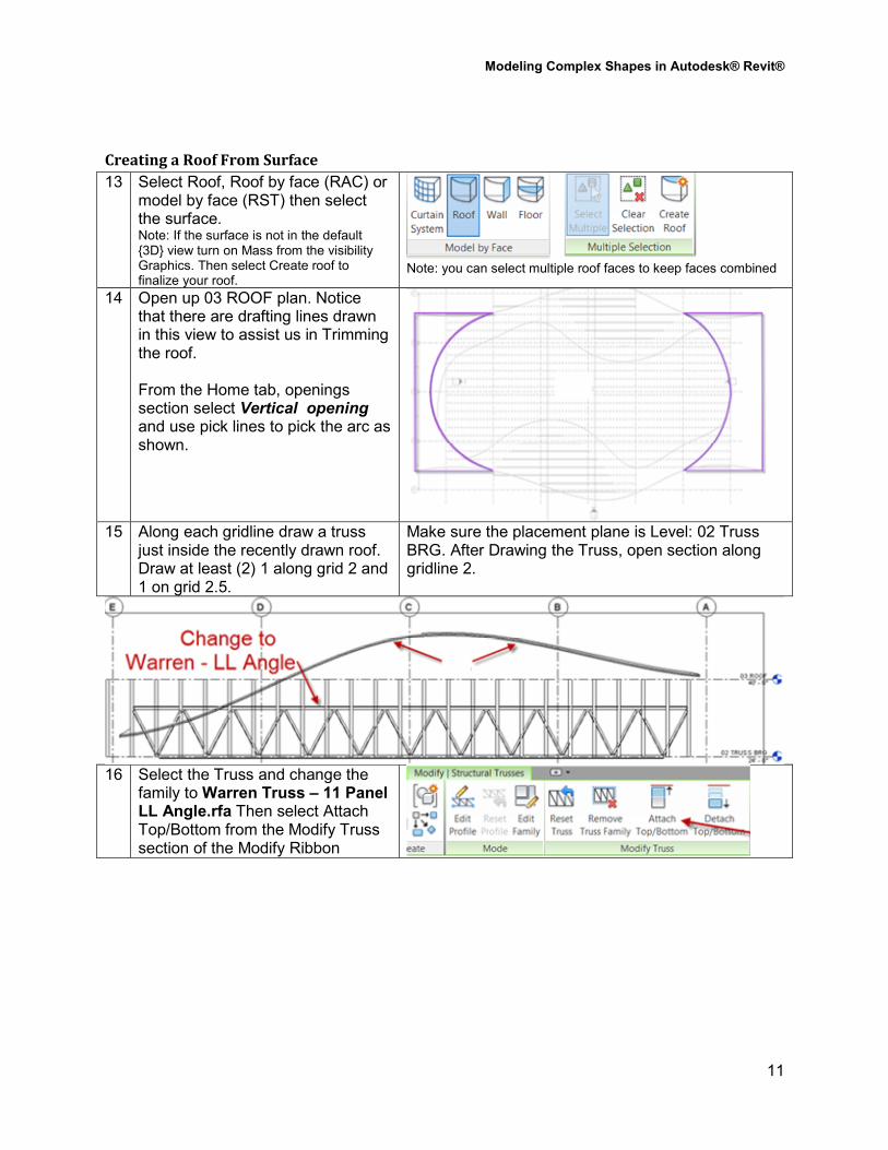
13 Select Roof, Roof by face (RAC) or model by face (RST) then select the surface. Note: If the surface is not in the default {3D} view turn on Mass from the visibility Graphics. Then select Create roof to finalize your roof.
Note: you can select multiple roof faces to keep faces combined
14 Open up 03 ROOF plan. Notice that there are drafting lines drawn in this view to assist us in Trimming the roof. From the Home tab, openings section select Vertical opening and use pick lines to pick the arc as shown.
15 Along each gridline draw a truss
just inside the recently drawn roof. Draw at least (2) 1 along grid 2 and 1 on grid 2.5.
Make sure the placement plane is Level: 02 Truss BRG. After Drawing the Truss, open section along gridline 2.
16 Select the Truss and change the
family to Warren Truss – 11 Panel LL Angle.rfa Then select Attach Top/Bottom from the Modify Truss section of the Modify Ribbon
Modeling Complex Shapes in Autodesk® Revit®
12
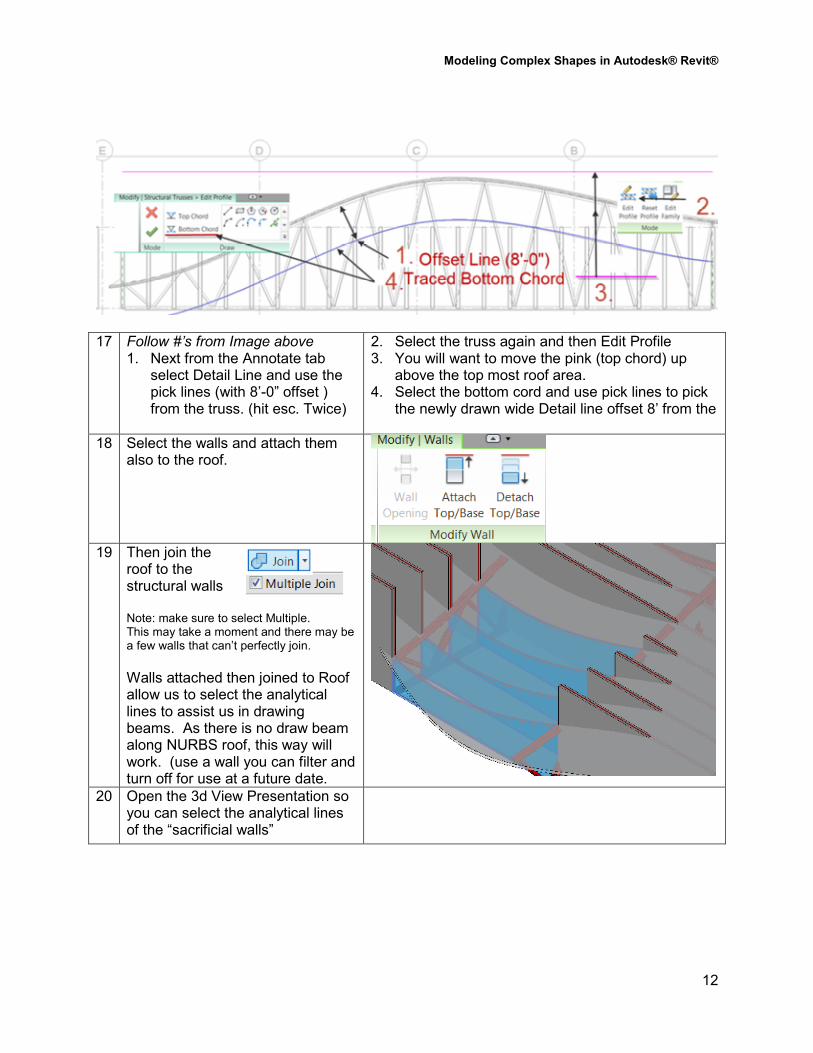
17 Follow #’s from Image above 1. Next from the Annotate tab
select Detail Line and use the pick lines (with 8’-0” offset ) from the truss. (hit esc. Twice)
2. Select the truss again and then Edit Profile 3. You will want to move the pink (top chord) up
above the top most roof area. 4. Select the bottom cord and use pick lines to pick
the newly drawn wide Detail line offset 8’ from the
18 Select the walls and attach them also to the roof.
19 Then join the
roof to the structural walls Note: make sure to select Multiple. This may take a moment and there may be a few walls that can’t perfectly join.
Walls attached then joined to Roof allow us to select the analytical lines to assist us in drawing beams. As there is no draw beam along NURBS roof, this way will work. (use a wall you can filter and turn off for use at a future date.
20 Open the 3d View Presentation so you can select the analytical lines of the “sacrificial walls”
Modeling Complex Shapes in Autodesk® Revit®
13
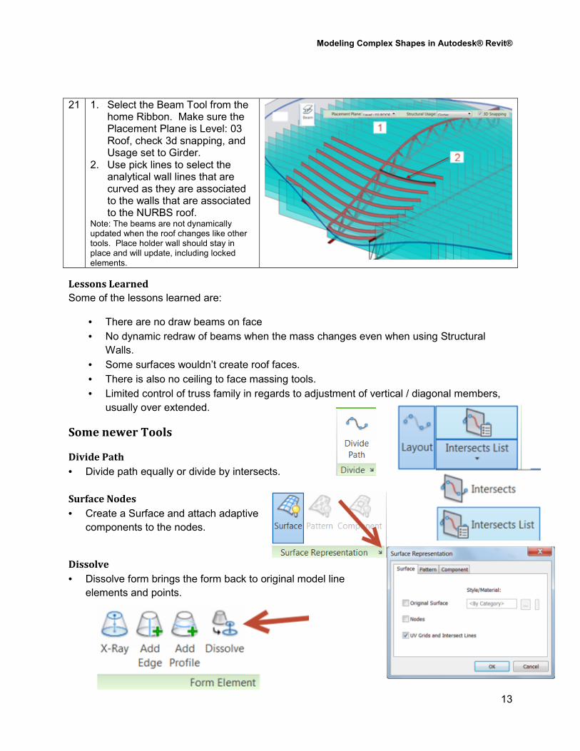
21 1. Select the Beam Tool from the home Ribbon. Make sure the Placement Plane is Level: 03 Roof, check 3d snapping, and Usage set to Girder.
2. Use pick lines to select the analytical wall lines that are curved as they are associated to the walls that are associated to the NURBS roof.
Note: The beams are not dynamically updated when the roof changes like other tools. Place holder wall should stay in place and will update, including locked elements.
Lessons Learned
Some of the lessons learned are:
• There are no draw beams on face
• No dynamic redraw of beams when the mass changes even when using Structural
Walls.
• Some surfaces wouldn’t create roof faces.
• There is also no ceiling to face massing tools.
• Limited control of truss family in regards to adjustment of vertical / diagonal members,
usually over extended.
Some newer Tools
Divide Path
• Divide path equally or divide by intersects.
Surface Nodes
• Create a Surface and attach adaptive
components to the nodes.
Dissolve
• Dissolve form brings the form back to original model line
elements and points.
Modeling Complex Shapes in Autodesk® Revit®
14
Lab 2 Tower Lab
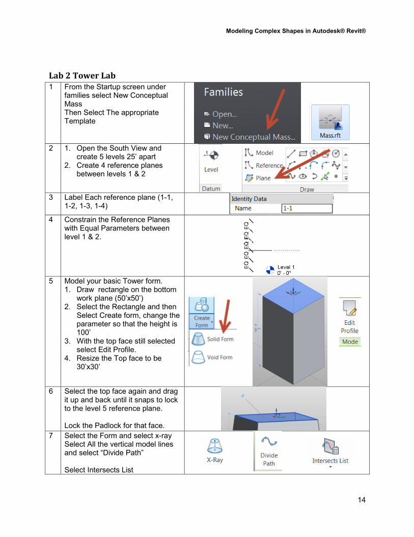
1 From the Startup screen under families select New Conceptual Mass Then Select The appropriate Template
2 1. Open the South View and
create 5 levels 25’ apart 2. Create 4 reference planes
between levels 1 & 2
3 Label Each reference plane (1-1,
1-2, 1-3, 1-4)
4 Constrain the Reference Planes with Equal Parameters between level 1 & 2.
5 Model your basic Tower form.
1. Draw rectangle on the bottom work plane (50’x50’)
2. Select the Rectangle and then Select Create form, change the parameter so that the height is 100’
3. With the top face still selected select Edit Profile.
4. Resize the Top face to be 30’x30’
6 Select the top face again and drag
it up and back until it snaps to lock to the level 5 reference plane. Lock the Padlock for that face.
7 Select the Form and select x-ray Select All the vertical model lines and select “Divide Path” Select Intersects List
Modeling Complex Shapes in Autodesk® Revit®
15
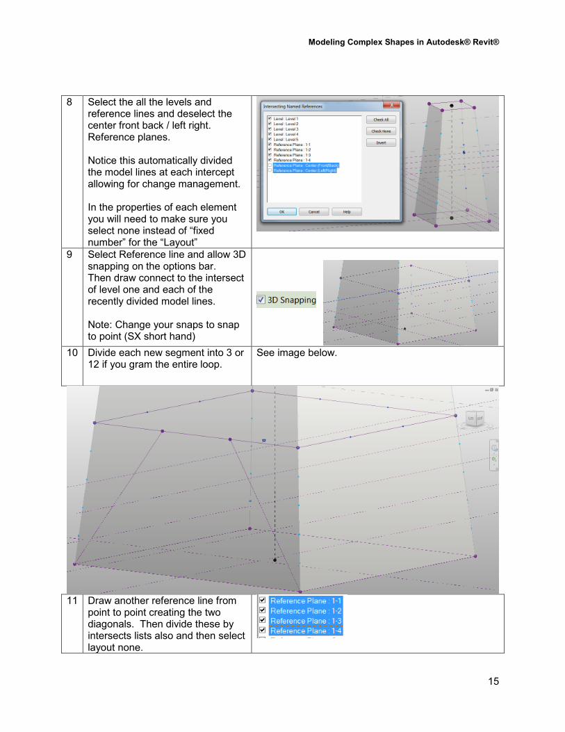
8 Select the all the levels and reference lines and deselect the center front back / left right. Reference planes. Notice this automatically divided the model lines at each intercept allowing for change management. In the properties of each element you will need to make sure you select none instead of “fixed number” for the “Layout”
9 Select Reference line and allow 3D snapping on the options bar. Then draw connect to the intersect of level one and each of the recently divided model lines. Note: Change your snaps to snap to point (SX short hand)
10 Divide each new segment into 3 or
12 if you gram the entire loop. See image below.
11 Draw another reference line from
point to point creating the two diagonals. Then divide these by intersects lists also and then select layout none.
Modeling Complex Shapes in Autodesk® Revit®
16
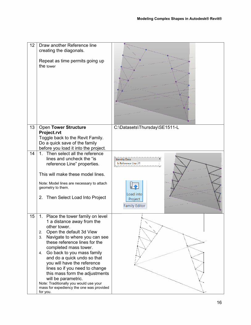
12 Draw another Reference line creating the diagonals. Repeat as time permits going up the tower
13 Open Tower Structure
Project.rvt Toggle back to the Revit Family. Do a quick save of the family before you load it into the project.
C:\Datasets\Thursday\SE1511-L
14 1. Then select all the reference lines and uncheck the “is reference Line” properties.
This will make these model lines. Note: Model lines are necessary to attach geometry to them.
2. Then Select Load Into Project
15 1. Place the tower family on level 1 a distance away from the other tower.
2. Open the default 3d View
3. Navigate to where you can see these reference lines for the completed mass tower.
4. Go back to you mass family and do a quick undo so that you will have the reference lines so if you need to change this mass form the adjustments will be parametric.
Note: Traditionally you would use your mass for expediency the one was provided for you.
Modeling Complex Shapes in Autodesk® Revit®
17
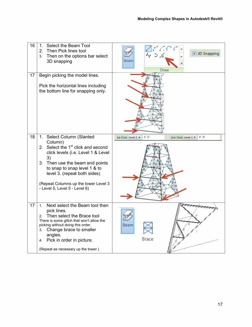
16 1. Select the Beam Tool 2. Then Pick lines tool 3. Then on the options bar select
3D snapping
17 Begin picking the model lines. Pick the horizontal lines including the bottom line for snapping only.
18 1. Select Column (Slanted
Column) 2. Select the 1st click and second
click levels (i.e. Level 1 & Level 3)
3. Then use the beam end points to snap to snap level 1 & to level 3. (repeat both sides)
(Repeat Columns up the tower Level 3 - Level 5, Level 5 - Level 6)
17 1. Next select the Beam tool then
pick lines. 2. Then select the Brace tool There is some glitch that won’t allow the picking without doing this order.
3. Change brace to smaller angles.
4. Pick in order in picture. (Repeat as necessary up the tower.)
Modeling Complex Shapes in Autodesk® Revit®
18
Tower Considerations / Planning
• Goal outline
o Create a mass
o Divide the mass constructs.
• Use reference planes to drive parametric geometry
• Constrain Reference planes (EQ parameters)
• Label Reference Planes so that you can use and identify them later.
• Create points along Reference lines that divide by Intersects list
• Create reference line structure between Points.
• Hosting elements for Structure
o Beams can only host to “model lines” as a straw man for laying out structure.
• Load Model line into project (the trick undo model line back to reference lines and save)
• Change Management Aspect
o When changes need to be made, make them in the original family per parametric
constraints and update to project family.
Modeling Complex Shapes in Autodesk® Revit®
19
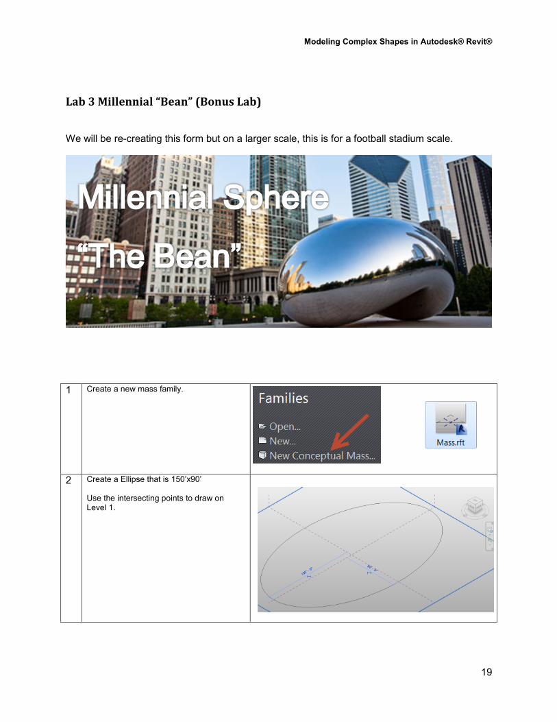
Lab 3 Millennial “Bean” (Bonus Lab)
We will be re-creating this form but on a larger scale, this is for a football stadium scale.
1 Create a new mass family.
2 Create a Ellipse that is 150’x90’ Use the intersecting points to draw on Level 1.
Modeling Complex Shapes in Autodesk® Revit®
20
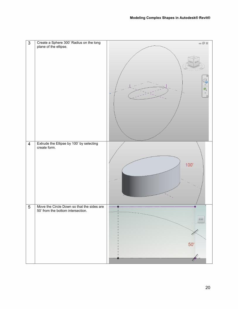
3 Create a Sphere 300’ Radius on the long plane of the ellipse.
4 Extrude the Ellipse by 100’ by selecting
create form.
5 Move the Circle Down so that the sides are
50’ from the bottom intersection.
Modeling Complex Shapes in Autodesk® Revit®
21
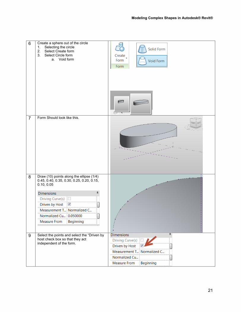
6 Create a sphere out of the circle 1. Selecting the circle 2. Select Create form 3. Select Circle form
a. Void form
7 Form Should look like this.
8 Draw (10) points along the ellipse (1/4)
0.45, 0.40, 0.35, 0.30, 0.25, 0.20, 0.15, 0.10, 0.05
9 Select the points and select the “Driven by
host check box so that they act independent of the form.
Modeling Complex Shapes in Autodesk® Revit®
22
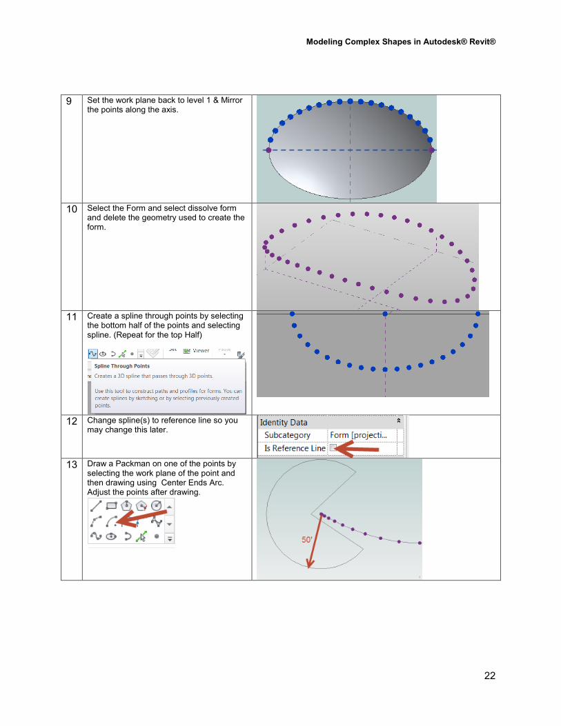
9 Set the work plane back to level 1 & Mirror the points along the axis.
10 Select the Form and select dissolve form
and delete the geometry used to create the form.
11 Create a spline through points by selecting
the bottom half of the points and selecting spline. (Repeat for the top Half)
12 Change spline(s) to reference line so you may change this later.
13 Draw a Packman on one of the points by
selecting the work plane of the point and then drawing using Center Ends Arc. Adjust the points after drawing.
Modeling Complex Shapes in Autodesk® Revit®
23
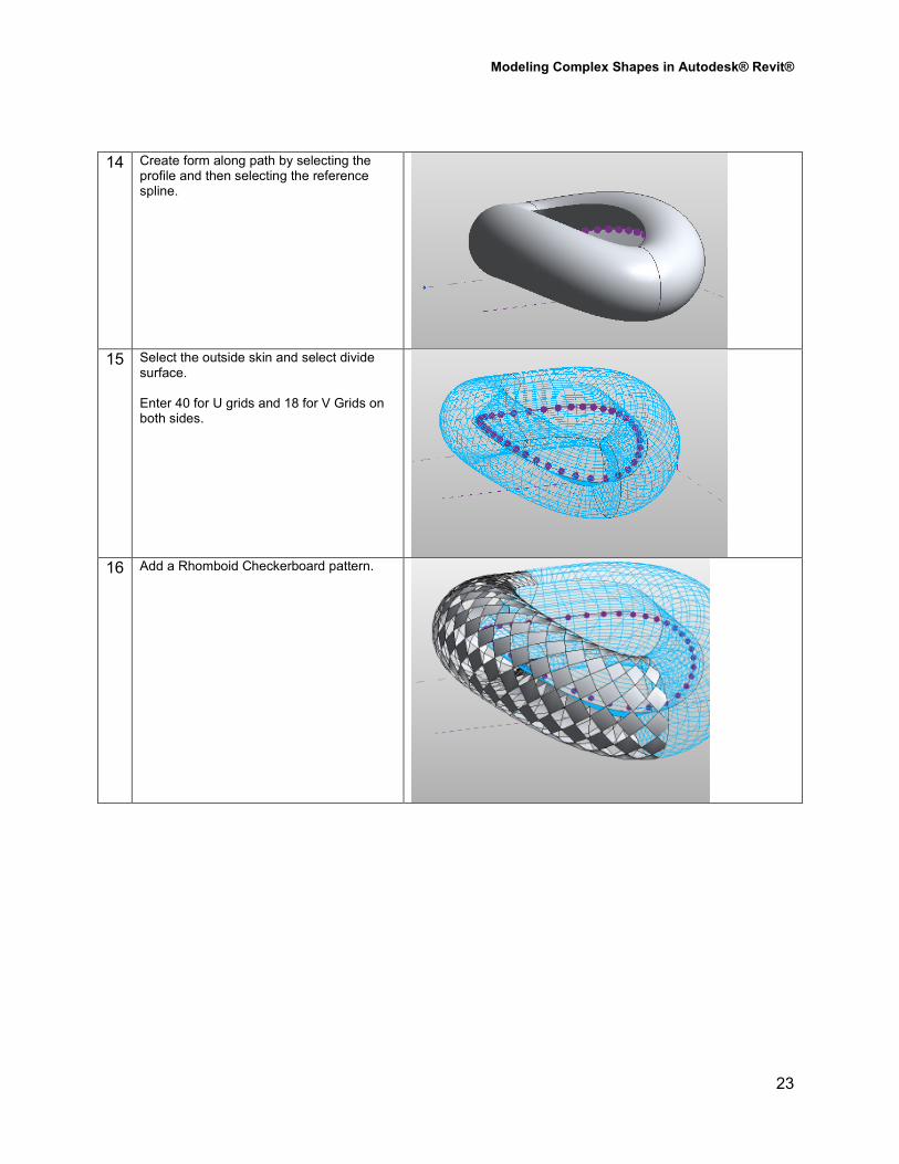
14 Create form along path by selecting the profile and then selecting the reference spline.
15 Select the outside skin and select divide
surface. Enter 40 for U grids and 18 for V Grids on both sides.
16 Add a Rhomboid Checkerboard pattern.